Embed Size (px)
Citation preview
MIL-DTL-8794F 16 April 2007 SUPERSEDING MIL-DTL-8794E 22 September 2000
DETAIL SPECIFICATION
HOSE, SYNTHETIC RUBBER - HYDRAULIC FLUID, FUEL, AND OIL RESISTANT This specification is approved for use by all Departments and Agencies of the Department of Defense. 1. SCOPE
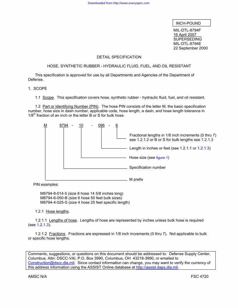
1.1 Scope. This specification covers hose, synthetic rubber - hydraulic fluid, fuel, and oil resistant. 1.2 Part or Identifying Number (PIN). The hose PIN consists of the letter M, the basic specification
number, hose size in dash number, applicable code, hose length, a dash, and hose length tolerance in 1/8th fraction of an inch or the letter B or S for bulk hose.
M 8794 - 10 - 096 - 6
PIN examples:
M8794-8-014-5 (size 8 hose 14 5/8 inches long) M8794-6-050-B (size 6 hose 50 feet bulk sizes) M8794-4-025-S (size 4 hose 25 feet specific length)
1.2.1 Hose lengths.
1.2.1.1 Lengths of hose. Lengths of hose are represented by inches unless bulk hose is required
(see 1.2.1.3). 1.2.1.2 Fractions. Fractions are expressed in 1/8 inch increments (0 thru 7). Not applicable to bulk
or specific hose lengths.
Comments, suggestions, or questions on this document should be addressed to: Defense Supply Center, Columbus, Attn: DSCC-VAI, P.O. Box 3990, Columbus, OH 43218-3990, or emailed to [email protected]. Since contact information can change, you may want to verify the currency of this address information using the ASSIST Online database at http://assist.daps.dla.mil.
Specification number
Hose size (see figure 1)
Length in inches or feet (see 1.2.1.1 or 1.2.1.3)
M prefix
Fractional lengths in 1/8 inch increments (0 thru 7) see 1.2.1.2 or B or S for bulk lengths see 1.2.1.3
INCH-POUND
AMSC N/A FSC 4720
Downloaded from http://www.everyspec.com
MIL-DTL-8794F
2
1.2.1.3 Bulk hose lengths. Bulk hose lengths are represented by the letter B or S. Bulk lengths are in increments of 20 feet or more (see 3.4.3.1). The S designator is used to define specific lengths in feet (see 3.4.3.2).
Note: For the inch designator insert the number zero in front of designator for lengths less than 100 inches.
Examples:
When 12 7/8 inch length is required the designator is: 012-7 When 96 inches is required the designator is: 096-0 When 30 feet total length is required the designator is: 030-B When 30 feet continuous length is required with a 1% tolerance the designator is: 030-S
2. APPLICABLE DOCUMENTS 2.1 General. The documents listed in this section are specified in sections 3, 4, or 5 of this specification. This section does not include documents cited in other sections of this specification or recommended for additional information or as examples. While every effort has been made to ensure the completeness of this list, document users are cautioned that they must meet all specified requirements documents cited in sections 3, 4, or 5 of this specification, whether or not they are listed.
2.2 Government documents.
2.2.1 Specifications standards, and handbooks. The following specifications, standards, and handbooks form a part of this document to the extent specified herein. Unless otherwise specified, the issues of these documents are those cited in the solicitation or contract.
FEDERAL STANDARDS
FED-STD-595/13538 - Yellow Gloss FED-STD-601 - Rubber: Sampling and Testing
DEPARTMENT OF DEFENSE SPECIFICATIONS
MIL-DTL-5070 - Adapter, Hose to Tube, Pipe, and Flange, Reusable - Hydraulic,
Fuel, and Oil Lines, General Specification for MIL-DTL-8795 - Hose Assemblies, Elastomeric - Hydraulic Fluid, Fuel, and Oil
Resistant, General Specification for MIL-PRF-5606 - Hydraulic Fluid, Petroleum Base; Aircraft, Missile, and Ordnance MIL-PRF-83282 - Hydraulic Fluid, Fire Resistant, Synthetic Hydrocarbon Base, Aircraft,
Metric, NATO Code Number H-537 MIL-PRF-87257 - Hydraulic Fluid, Fire Resistant; Low Temperature, Synthetic
Hydrocarbon Base, Aircraft and Missile
Downloaded from http://www.everyspec.com

MIL-DTL-8794F
3
DEPARTMENT OF DEFENSE STANDARDS
MS28741 - Hose Assembly, Detachable End Fitting, Medium Pressure (Copies of these documents are available online at http://assist.daps.dla.mil/quicksearch/ or http://assist.daps.dla.mil or from the Standardization Document Order Desk, 700 Robbins Avenue, Building 4D, Philadelphia, PA 19111-5094.) 2.3 Non-Government publications. The following documents form a part of this document to the extent specified herein. Unless otherwise specified, the issues of these documents are those cited in the solicitation or contract. ASTM INTERNATIONAL ASTM D380 - Standard Test Methods for Rubber Hose ASTM D413 - Standard Test Methods for Rubber Property-Adhesion to Flexible
Substrate ASTM D471 - Standard Test Method for Rubber Property-Effect of Liquids (Copies of these documents are available online at http://www.astm.org or from ASTM International, P.O. Box C700, 100 Barr Harbor Drive, West Conshohocken, PA 19428-2959.) NCSL INTERNATIONAL NCSL Z540.1 - Calibration Laboratories and Measuring and Test Equipment, General
Requirements (Copies of these documents are available online at http://www.ncsli.org or from NCSL International 2995 Wilderness Place, Suite 107 Boulder, Colorado 80301-5404.) SAE INTERNATIONAL SAE ARP603 - Impulse Testing of Hydraulic Hose Tubing and Fitting Assemblies SAE AS1933 - Age Controls for Hose Containing Age-Sensitive Elastomeric Material SAE J1966 - Lubricating Oil, Aircraft Piston Engine (Nondispersant Mineral Oil)
(Copies of these documents are available from http://www.sae.org/ or from SAE International, 400 Commonwealth Drive, Warrendale, PA 15096-0001.) 2.4 Order of precedence. In the event of a conflict between the text of this document and the references cited herein, the text of this document takes precedence. Nothing in this document, however, supersedes applicable laws and regulations unless a specific exemption has been obtained. 3. REQUIREMENTS 3.1 Qualification. Hose furnished under this specification shall be products that are authorized by the qualifying activity for listing on the applicable qualified products list before contract award (see 4.5 and 6.3). 3.2 Materials. Hose shall be uniform in quality and free from defects in materials. Materials shall conform to the requirements specified herein. When a specific material is not called out, a material shall be used that will meet the performance requirements of this specification.
Downloaded from http://www.everyspec.com

MIL-DTL-8794F
4
3.2.1 Recycled, recovered, or environmentally preferable materials. Recycled, recovered, or environmentally preferable materials should be used to the maximum extent possible, provided that the material meets or exceeds the operational and maintenance requirements, and promotes economically advantageous life cycle cost.
3.2.2 Hazardous substances. The use of hazardous substances, toxic chemicals, or ozone depleting chemicals shall be avoided whenever feasible. 3.3 Construction. 3.3.1 Elastomeric inner tube. The portion of the hose that is in contact with the fluids being conveyed shall be a seamless synthetic rubber. The internal surface of the tube shall have a smooth bore and shall be free from pitting. The synthetic rubber shall be compatible with hydraulic fluid, fuel, and oil (see 3.3.7). 3.3.2 Reinforcing material. Hose shall contain a reinforcing wire braid which consists of one fiber braid and one high tensile steel wire braid (CRES). The wire braid shall be braided to resist tension so as to provide strength and limit expansion of the hose to a minimum. No length of hose shall contain missing, broken or spliced wire braid or reinforcing material. 3.3.3 Outer cover. The outer cover shall consist of fiber braid impregnated with oil and between two layers of synthetic rubber. The outer cover of the hose shall be oil and fungus resistant. 3.3.4 Vulcanization. The entire construction shall be vulcanized. 3.3.5 Operating temperature. Hose shall be capable of operating in ambient temperatures as specified in table I.
TABLE I. Hose temperature application.
Application/operating temperature range 1/ Hose size Hydraulic Fuel Oil -3 N/A 2/ -4 -5
-65°F to +275°F (-53.9°C to 135°C)
-6 -8 -10 -12
-65°F to +160 F (-53.9°C to 71.1°C)
-65°F to 160 F (-53.9°C to 71.1°C)
-65°F to 250 F (-53.9°C to 121.1°C)
-16 -20 -24 -32 -40 -48
-40°F to 160 F (-40°C to 71.1°C)
-40°F to 160 F (-40°C to 71.1°C)
-40°F to 160 F (-40°C to 71.1°C)
1/ Temperature range - ambient and internal fluid. 2/ Size -3 shall not be used in hydraulic applications.
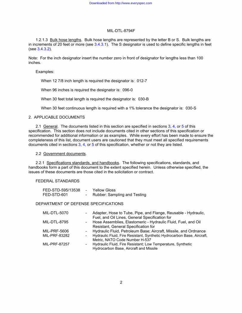
3.3.6 Operating pressure. Hose shall withstand the operating pressures specified in table II without leakage or evidence of imperfections.
Downloaded from http://www.everyspec.com
MIL-DTL-8794F
5
TABLE II. Performance requirements of hose assemblies. 1/
Length Minimum Hydraulic Fuel Oil Size (dash
number)
of hose assemblies for all tests (inches) 2/
bend radius at inside of bend (inches)
Operating pressure
(psi)
Proof pressure
(psi)
Operatingpressure
(psi)
Proof pressure
(psi)
Operatingpressure
(psi)
Surge pressure
(psi)
Proof pressure
(psi)
Burst pressure
(psi)
-3 3/ 14 3 N/A N/A 1,000 1,500 50 400 600 4,000 -4 14 3 3,000 6,000 1,000 1,500 50 400 600 12,000 -5 16 3.375 6,000 12,000 1,000 1,500 50 400 600 10,000 -6 18 4 2,000 4,500 1,000 1,500 50 400 600 9,000 -8 21 4.625 2,000 4,000 1,000 1,500 50 400 600 8,000 -10 23.5 5.5 1,750 3,500 1,000 1,500 50 400 600 7,000 -12 27.5 6.5 1,500 3,000 1,000 1,500 50 400 600 6,000 -16 18 7.375 800 1,600 750 1,000 50 400 600 3,200 -20 18 9 600 1,250 500 750 50 400 600 2,500 -24 18 11 500 1,000 250 375 50 400 600 2,000 -32 18 13.25 350 700 200 300 50 400 600 1,400 -40 18 24 N/A N/A 200 300 N/A N/A N/A 1,000 -48 18 33 N/A N/A 200 300 N/A N/A N/A 800
1/ Assembled with adapters in accordance with MIL-DTL-5070. 2/ Except as otherwise specified in the individual test description. 3/ Size -3 shall not be used in hydraulic applications.
3.3.7 Hose assembly. Hose shall be installed with MIL-DTL-5070 adapters conforming to MIL-DTL-8795 hose assembly 3.3.8 Fluids. Hose shall be used with petroleum based, synthetic based, or hydrocarbon based hydraulic fluids, pneumatic, coolant, fuels and oils.
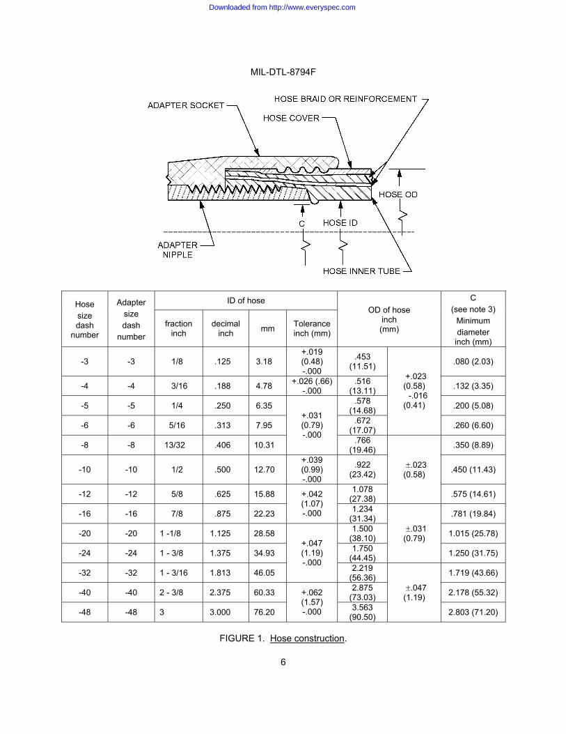
3.3.9 Cleanliness. The interior surface of the hose shall be free from oil, grease, dirt, moisture, cleaning solvents and foreign materials. 3.4 Dimensions. 3.4.1 Diameters. The inside and out side diameters shall be as specified on figure 1.
Downloaded from http://www.everyspec.com
MIL-DTL-8794F
6
ID of hose Hose size dash
number
Adapter size dash
number fraction
inch decimal
inch mm Tolerance inch (mm)
OD of hose inch (mm)
C (see note 3)
Minimum diameter
inch (mm)
-3 -3 1/8 .125 3.18 +.019 (0.48) -.000
.453 (11.51) .080 (2.03)
-4 -4 3/16 .188 4.78 +.026 (.66) -.000
.516 (13.11) .132 (3.35)
-5 -5 1/4 .250 6.35 .578 (14.68) .200 (5.08)
-6 -6 5/16 .313 7.95 .672 (17.07)
+.023 (0.58)
-.016 (0.41)
.260 (6.60)
-8 -8 13/32 .406 10.31
+.031 (0.79) -.000 .766
(19.46) .350 (8.89)
-10 -10 1/2 .500 12.70 +.039 (0.99) -.000
.922 (23.42) .450 (11.43)
-12 -12 5/8 .625 15.88 1.078 (27.38)
.023 (0.58)
.575 (14.61)
-16 -16 7/8 .875 22.23
+.042 (1.07) -.000 1.234
(31.34) .781 (19.84)
-20 -20 1 -1/8 1.125 28.58 1.500 (38.10) 1.015 (25.78)
-24 -24 1 - 3/8 1.375 34.93 1.750 (44.45)
.031 (0.79)
1.250 (31.75)
-32 -32 1 - 3/16 1.813 46.05
+.047 (1.19) -.000 2.219
(56.36) 1.719 (43.66)
-40 -40 2 - 3/8 2.375 60.33 2.875 (73.03) 2.178 (55.32)
-48 -48 3 3.000 76.20
+.062 (1.57) -.000 3.563
(90.50)
.047 (1.19)
2.803 (71.20)
FIGURE 1. Hose construction.
Downloaded from http://www.everyspec.com

MIL-DTL-8794F
7
NOTES: 1. Dimensions are in inches 2. Metric equivalents are given for information only. 3. C diameter indicates maximum permissible bulge of inner synthetic rubber tube when hose is
assembled with adapters.
FIGURE 1. Hose construction - Continued. 3.4.2 Concentricity.
3.4.2.1 Concentricity (hose sizes -3 through -8). The outer surface of the hose shall be concentric with the inside bore of the synthetic rubber tube within .020 inch (0.05 mm) total indicator reading. The variation in concentricity between the inside bore of the synthetic rubber tube and the OD of the reinforcing material shall not exceed these same values.
3.4.2.2 Concentricity (hose sizes -10 through -48). The outer surface of the hose shall be concentric
with the inside bore of the synthetic rubber tube within .030 inch (0.08 mm) total indicator reading. The variation in concentricity between the inside bore of the synthetic rubber tube and the OD of the reinforcing material shall not exceed these same values.
3.4.3 Length of bulk hose. 3.4.3.1 B designator of bulk hose lengths. Bulk hose shall be furnished in lengths greater than 20
feet (6.10 m). However, up to 10% of the order may be furnished in random lengths between 10 and 20 feet (3.05 to 6.10 m). No more than 10% of the order shall be furnished in random lengths between 3 and 10 feet (0.91 to 3.05 m).
3.4.3.2 S designator for specific bulk hose lengths. When the order is for a specific length in feet, a
tolerance of 1% of the required length shall be used. 3.5 Performance.
3.5.1 Materials performance. 3.5.1.1 Tensile strength and elongation of rubber. When tested as specified in 4.8.2, the tensile strength shall be a minimum of 2200 psi (16.17 MPa) and the elongation shall be a minimum of 200%. 3.5.1.2 Adhesion (hose size -12 through -48). When tested as specified in 4.8.3, strip specimens shall be tested for adhesion between the inner tube and inner cotton braid, and inner cotton braid and wire braid. The synthetic rubber tube and the inner layer of reinforcing material, and between layers of reinforcing material, shall be at least 10 pounds per inch, and 5 pounds per inch for an oil aged sample. 3.5.2 Synthetic rubber tube performance. 3.5.2.1 Water and alcohol resistance. After exposure to a mix of water and alcohol as specified in 4.8.4, the synthetic rubber tube tensile strength shall not exceed 35 percent, based on the original cross-sectional area of the synthetic rubber tube, see 3.5.1.1. 3.5.2.2 Fuel resistance. After exposure to fuel, the tensile strength of the synthetic rubber tube shall not be less than 1,000 psi (69 bar) when tested as specified in 4.8.5, the elongation shall be not less than 100 percent, and the volume increase shall not exceed 30 percent for hose sizes -12 and smaller, and shall not exceed 60 percent for hose sizes greater than size -12.
Downloaded from http://www.everyspec.com
MIL-DTL-8794F
8
3.5.3 Proof pressure. Hose when as specified in 4.8.6, shall withstand the applicable hydraulic proof pressures specified in table II without leakage or evidence of imperfections. 3.5.4 Reduction in diameter. Hose when tested as specified in 4.8.7, the ID of the hose shall not decrease to less than 90 percent of the minimum ID specified on figure 1.
3.5.5 Impulse test.
3.5.5.1 Impulse test (hose assembles of sizes -4 through -16). Hose assemblies sizes -4 through -16 when tested as specified in 4.8.8, shall withstand not less than 200,000 dynamic hydraulic impulse cycles, at a nominal rate of 70 pulses per minute at 125 percent of the hydraulic operating pressure specified in table II, without leakage, deformation, or separation from an adapter.
3.5.5.2 Impulse test (hose assembles of sizes -20 through -32). Hose assembles of sizes -20
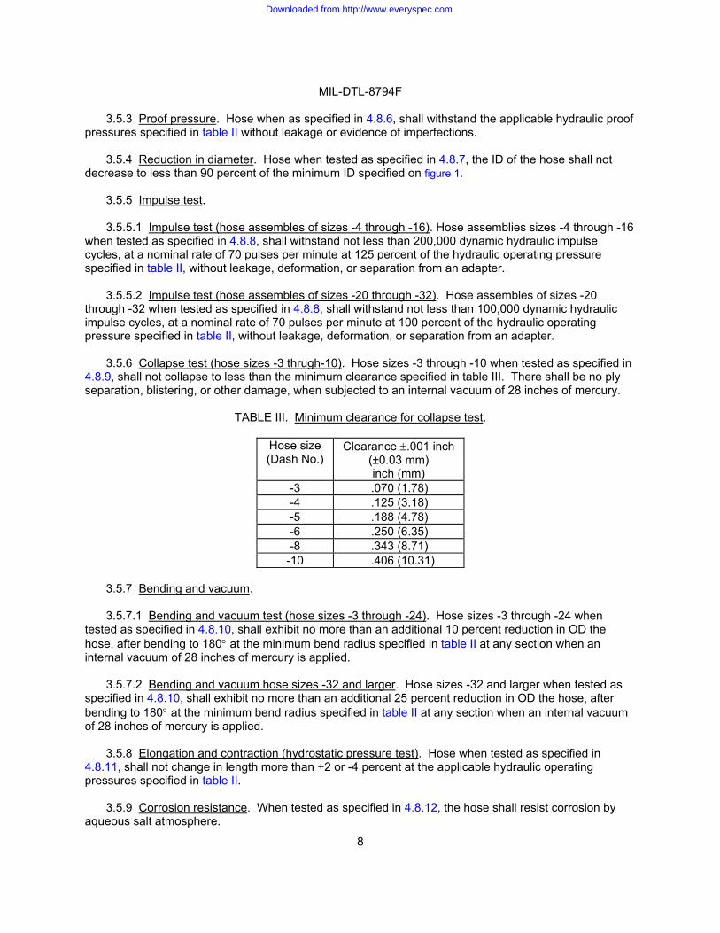
through -32 when tested as specified in 4.8.8, shall withstand not less than 100,000 dynamic hydraulic impulse cycles, at a nominal rate of 70 pulses per minute at 100 percent of the hydraulic operating pressure specified in table II, without leakage, deformation, or separation from an adapter. 3.5.6 Collapse test (hose sizes -3 thrugh-10). Hose sizes -3 through -10 when tested as specified in 4.8.9, shall not collapse to less than the minimum clearance specified in table III. There shall be no ply separation, blistering, or other damage, when subjected to an internal vacuum of 28 inches of mercury.
TABLE III. Minimum clearance for collapse test.
Hose size (Dash No.)
Clearance .001 inch (±0.03 mm) inch (mm)
-3 .070 (1.78) -4 .125 (3.18) -5 .188 (4.78) -6 .250 (6.35) -8 .343 (8.71)
-10 .406 (10.31)
3.5.7 Bending and vacuum.
3.5.7.1 Bending and vacuum test (hose sizes -3 through -24). Hose sizes -3 through -24 when tested as specified in 4.8.10, shall exhibit no more than an additional 10 percent reduction in OD the hose, after bending to 180 at the minimum bend radius specified in table II at any section when an internal vacuum of 28 inches of mercury is applied.
3.5.7.2 Bending and vacuum hose sizes -32 and larger. Hose sizes -32 and larger when tested as
specified in 4.8.10, shall exhibit no more than an additional 25 percent reduction in OD the hose, after bending to 180 at the minimum bend radius specified in table II at any section when an internal vacuum of 28 inches of mercury is applied.
3.5.8 Elongation and contraction (hydrostatic pressure test). Hose when tested as specified in 4.8.11, shall not change in length more than +2 or -4 percent at the applicable hydraulic operating pressures specified in table II.
3.5.9 Corrosion resistance. When tested as specified in 4.8.12, the hose shall resist corrosion by aqueous salt atmosphere.
Downloaded from http://www.everyspec.com
MIL-DTL-8794F
9
3.5.10 Burst pressure. Hose when tested as specified in 4.8.13, shall not burst or cause adapters to loosen or separate from the hose, and there shall be no external leakage from the hose or hose-to-adapter interface, at any pressure up to the burst pressure specified in table II.
3.5.11 Low temperature flexing. 3.5.11.1 Low temperature flexing (hose sizes -3 through -12). Hose sizes -3 through -12 when
tested as specified in 4.8.14, shall be capable of being flexed through 180 of bend in approximately 4 seconds to the bend radius specified in table I at -65 F (-53.9°C) without leakage.
3.5.11.2 Low temperature flexing (hose sizes -16 and larger). Hose sizes -16 and larger shall be
capable of being flexed through 180° of bend in approximately 4 seconds to the bend radius specified in table I at -40 F (-40°C) without leakage. 3.5.12 Bulge. When tested as specified in 4.8.15, the bulge of the synthetic rubber tube of the hose when assembled with adapters conforming to MIL-DTL-5070 shall not reduce the ID of the hose to less than the C dimension shown on figure 1.
3.5.13 Fuel immersion. When tested as specified in 4.8.16, the hose and the hose-to-adapter interface shall not leak after immersion in fuels. The hose shall be visually inspected and there shall be no indication of disintegration, such as ply separation, solubility of component parts, porosity, blistering, or collapse. 3.5.14 Lubricating oil circulation.
3.5.14.1 Lubricating oil circulation (hose size -3 through -12). Hose size -3 through -12 when tested as specified in 4.8.17, shall be capable of circulating oil at fluid temperatures up to 250 F (121.1°C) and under surge conditions of 325°F (162.8°C) without leakage operating at the oil operating pressures specified in table II.
3.5.14.2 Lubricating oil circulation (hose size -16 and larger). Hose size -16 and larger when tested
as specified in 4.8.17, shall be capable of circulating oil at fluid temperature up to 160 F (71.1°C) and under surge conditions of 325°F (162.8°C) without leakage while operating at the oil operating pressures specified in table II.
3.5.15 Volumetric expansion. 3.5.15.1 Volumetric expansion (hose size -3, -4, and -5). Hose size -3 and -4 when tested as
specified in 4.8.18, shall be not greater than .06 cubic centimeter per inch of free length at 1,000 pounds per square inch (psi) pressure. The volumetric expansion of size -5 hose when tested as specified in 4.8.18, shall be not greater than .08 cubic centimeter per inch of free length at 1,000 psi (68.9 bar) pressure.
3.5.15.2 Volumetric expansion (hose size -6 and larger). There are no volumetric expansion limits
for size -6 hose and larger.
Downloaded from http://www.everyspec.com
MIL-DTL-8794F
10
3.5.16 Leakage. Hose assemblies when tested as specified in 4.8.19, shall have no leakage of the hose or from the hose-to-adapter interface, and no seepage back through the fabric that might produce separation or swelling of the hose, when subjected to 70 percent of the burst pressure specified in table II.
3.6 Marking. The outer cover of bulk hose or hose in hose assemblies shall be marked with, continuous yellow stripe. As a minimum, the hose cover material shall be marked with the following information at intervals of not more than 12 inches (305 mm).
a. PIN as specified in 1.2, length designator may be omitted. b. Cure date in quarter and year such as 4Q06 for fourth quarter 2006. c. CAGE code. d. Manufacturer’s name or trademark.
(Example: “MIL-DTL-8794-6-2Q06-00TBD” designates hose size -6 manufactured during the second
quarter of calendar year 2006 by the manufacturer whose CAGE Code is 00TBD.) 3.6.1 Marking color. The marking color shall be yellow conforming to FED-STD-595/13538. The
marking shall be a water resistant, gasoline resistant, and oil-resistant.
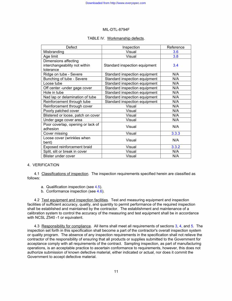
3.7 Workmanship. Hose shall be manufactured and processed in such a manner as to be uniform in quality and shall be free from foreign material and other defects that will affect life, serviceability, strength, assembly or durability, see table IV. Workmanship shall be such as to enable the hose to meet the applicable performance requirements of this specification.
3.8 Age limit. The age limit of bulk hose and hose assemblies covered by this specification and furnished for use by the Government shall not exceed the limits in accordance with SAE AS1933.
Downloaded from http://www.everyspec.com
MIL-DTL-8794F
11
TABLE IV. Workmanship defects.
Defect Inspection Reference Misbranding Visual 3.6 Age limit Visual 3.8 Dimensions affecting interchangeability not within tolerance
Standard inspection equipment 3.4
Ridge on tube - Severe Standard inspection equipment N/A Bunching of tube - Severe Standard inspection equipment N/A Loose tube Standard inspection equipment N/A Off center -under gage cover Standard inspection equipment N/A Hole in tube Standard inspection equipment N/A Nad lap or delamination of tube Standard inspection equipment N/A Reinforcement through tube Standard inspection equipment N/A Reinforcement through cover Visual N/A Poorly patched cover Visual N/A Blistered or loose, patch on cover Visual N/A Under gage cover area Visual N/A Poor coverlap, opening or lack of adhesion Visual N/A
Cover missing Visual 3.3.3 Loose cover (wrinkles when bent) Visual N/A
Exposed reinforcement braid Visual 3.3.2 Split, slit or break in cover Visual N/A Blister under cover Visual N/A
4. VERIFICATION
4.1 Classifications of inspection. The inspection requirements specified herein are classified as follows: a. Qualification inspection (see 4.5). b. Conformance inspection (see 4.6).
4.2 Test equipment and inspection facilities. Test and measuring equipment and inspection facilities of sufficient accuracy, quality, and quantity to permit performance of the required inspection shall be established and maintained by the contractor. The establishment and maintenance of a calibration system to control the accuracy of the measuring and test equipment shall be in accordance with NCSL Z540 -1 or equivalent.
4.3 Responsibility for compliance. All items shall meet all requirements of sections 3, 4, and 5. The
inspection set forth in this specification shall become a part of the contractor's overall inspection system or quality program. The absence of any inspection requirements in the specification shall not relieve the contractor of the responsibility of ensuring that all products or supplies submitted to the Government for acceptance comply with all requirements of the contract. Sampling inspection, as part of manufacturing operations, is an acceptable practice to ascertain conformance to requirements, however, this does not authorize submission of known defective material, either indicated or actual, nor does it commit the Government to accept defective material.
Downloaded from http://www.everyspec.com
MIL-DTL-8794F
12
4.4 Hose assemblies for hose testing. The hose assemblies used for hose testing shall be assembled using adapters in accordance with MIL-DTL-5070 of the applicable size in accordance with the adapter manufacturer’s instructions (see MIL-DTL-8795 and MS28741). Hose assemblies shall be examined to verify that there has been no degradation of the hose or adapters resulting from the assembly process. Unless otherwise specified, hose assembly lengths shall be as specified in table II.
4.5 Qualification inspection. Qualification inspection shall be performed at a laboratory acceptable to the
qualifying activity on sample units produced with equipment and procedures used in production. Each nominal hose size (ID) shall be qualified individually.
4.5.1 Samples for qualification. Samples for qualification shall be representative of the products
proposed to be furnished to the Government. Samples shall be of one type and nominal size of hose and shall be of the quantity and length specified in the applicable test method.
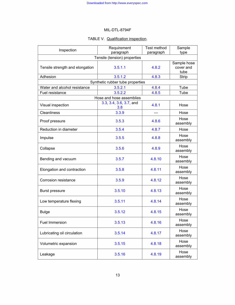
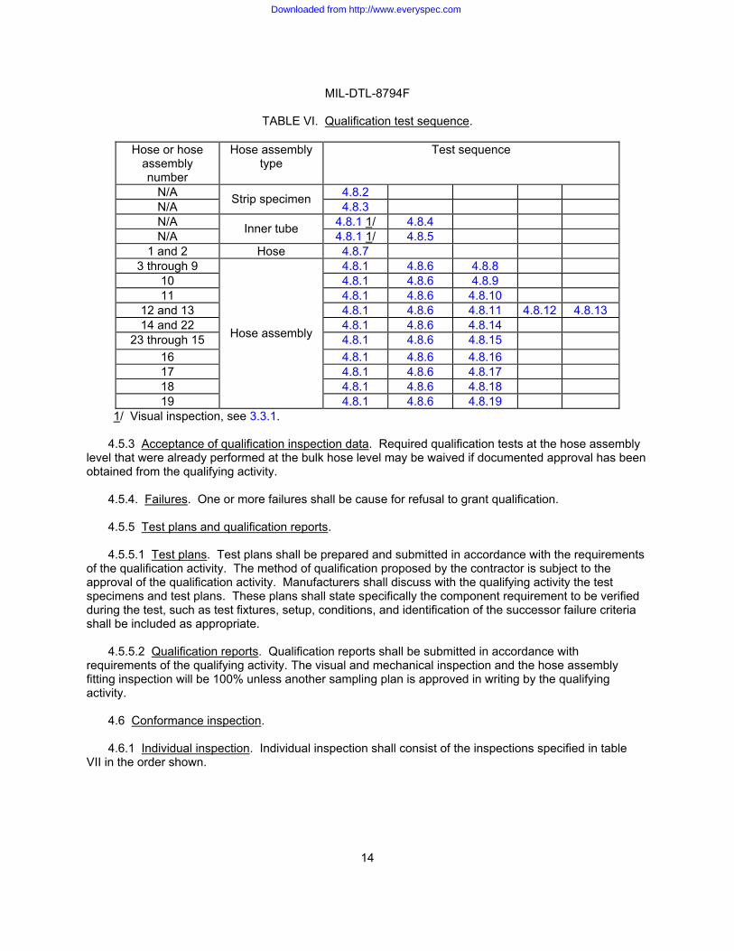
4.5.2 Qualification inspection routine. All samples shall be subjected to qualification testing as specified
in table V and the test sequence as specified in table VI. 4.5.3 Disposition of test specimens. Test specimens that have been subjected to qualification
testing shall not be delivered on a contract or purchase order.
Downloaded from http://www.everyspec.com
MIL-DTL-8794F
13
TABLE V. Qualification inspection.
Inspection Requirement paragraph
Test method paragraph
Sample type
Tensile (tension) properties
Tensile strength and elongation 3.5.1.1 4.8.2 Sample hose
cover and tube
Adhesion 3.5.1.2 4.8.3 Strip Synthetic rubber tube properties
Water and alcohol resistance 3.5.2.1 4.8.4 Tube Fuel resistance 3.5.2.2 4.8.5 Tube
Hose and hose assemblies
Visual inspection 3.3, 3.4, 3.6, 3.7, and 3.8 4.8.1 Hose
Cleanliness 3.3.9 --- Hose
Proof pressure 3.5.3 4.8.6 Hose assembly
Reduction in diameter 3.5.4 4.8.7 Hose
Impulse 3.5.5 4.8.8 Hose assembly
Collapse 3.5.6 4.8.9 Hose assembly
Bending and vacuum 3.5.7 4.8.10 Hose assembly
Elongation and contraction 3.5.8 4.8.11 Hose assembly
Corrosion resistance 3.5.9 4.8.12 Hose assembly
Burst pressure 3.5.10 4.8.13 Hose assembly
Low temperature flexing 3.5.11 4.8.14 Hose assembly
Bulge 3.5.12 4.8.15 Hose assembly
Fuel Immersion 3.5.13 4.8.16 Hose assembly
Lubricating oil circulation 3.5.14 4.8.17 Hose assembly
Volumetric expansion 3.5.15 4.8.18 Hose assembly
Leakage 3.5.16 4.8.19 Hose assembly
Downloaded from http://www.everyspec.com
MIL-DTL-8794F
14
TABLE VI. Qualification test sequence.
Hose or hose assembly number
Hose assembly type
Test sequence
N/A 4.8.2 N/A Strip specimen 4.8.3 N/A 4.8.1 1/ 4.8.4 N/A Inner tube 4.8.1 1/ 4.8.5
1 and 2 Hose 4.8.7 3 through 9 4.8.1 4.8.6 4.8.8
10 4.8.1 4.8.6 4.8.9 11 4.8.1 4.8.6 4.8.10
12 and 13 4.8.1 4.8.6 4.8.11 4.8.12 4.8.13 14 and 22 4.8.1 4.8.6 4.8.14
23 through 15 4.8.1 4.8.6 4.8.15 16 4.8.1 4.8.6 4.8.16 17 4.8.1 4.8.6 4.8.17 18 4.8.1 4.8.6 4.8.18 19
Hose assembly
4.8.1 4.8.6 4.8.19 1/ Visual inspection, see 3.3.1.
4.5.3 Acceptance of qualification inspection data. Required qualification tests at the hose assembly
level that were already performed at the bulk hose level may be waived if documented approval has been obtained from the qualifying activity.
4.5.4. Failures. One or more failures shall be cause for refusal to grant qualification. 4.5.5 Test plans and qualification reports. 4.5.5.1 Test plans. Test plans shall be prepared and submitted in accordance with the requirements
of the qualification activity. The method of qualification proposed by the contractor is subject to the approval of the qualification activity. Manufacturers shall discuss with the qualifying activity the test specimens and test plans. These plans shall state specifically the component requirement to be verified during the test, such as test fixtures, setup, conditions, and identification of the successor failure criteria shall be included as appropriate.
4.5.5.2 Qualification reports. Qualification reports shall be submitted in accordance with
requirements of the qualifying activity. The visual and mechanical inspection and the hose assembly fitting inspection will be 100% unless another sampling plan is approved in writing by the qualifying activity.
4.6 Conformance inspection.
4.6.1 Individual inspection. Individual inspection shall consist of the inspections specified in table
VII in the order shown.
Downloaded from http://www.everyspec.com

MIL-DTL-8794F
15
TABLE VII. Individual inspections.
Inspections Requirement
paragraph Inspection paragraph
Visual inspection 1/ 3.3, 3.4, 3.6, 3.7, and 3.8 4.8.1 Proof pressure 3.5.3 4.8.6 1/ 100 percent inspection of the bulk hose length unless an alternate sampling plan is
approved in writing by the qualifying activity. 4.6.2. Individual inspections sampling plan. Individual inspection tests specified in table VII shall be
performed on a production lot basis. All defective material will be removed from the production lot and shall not be supplied to this specification
4.6.3 Sampling inspection lot. 4.6.3.1 Sampling for bulk hose. Sampling for bulk hose shall be performed on each continuous run
under essentially the same conditions. Samples shall be selected at a rate of 1 sample for each full or partial increment of 750 feet (228.60 m) of hose produced in the continuous run, up to a maximum of 2 samples (for continuous runs greater than 1,500 feet (457.20 m), 2 samples shall be selected, but they shall be representative of the entire production run). Sampling tests for length change, leakage, and burst shall be performed in the listed order on each sample as applicable. When a hose assembly is specified in the test method, a hose assembly shall consist of the hose as specified herein, coupled with fittings as specified in 3.3.6.
4.6.4 Sampling and periodic inspections. Sampling and periodic inspections shall consist of the
inspections specified in table VIII and shall be performed on test samples selected from production lot(s) that has been subjected to and passed the individual inspections (see table VII).
TABLE VIII. Sampling and periodic inspections.
Inspections Requirement
paragraph Inspection paragraph Sampling Periodic
Elongation and contraction 3.5.8 4.8.11 X --- Leakage 3.5.16 4.8.19 X Burst pressure 3.5.10 4.8.13 X --- Impulse 3.5.5 4.8.8 --- X Collapse 3.5.6 4.8.9 --- X Adhesion 3.5.1.2 4.8.3 --- X
4.6.4.1 Periodic testing sampling plan. 4.6.4.2 Periodic quality conformance inspection (QCI) (bulk hose) . Four (4) samples shall be tested
to each required periodic test for each production of 20,000 feet (6096 m) (large lot option) of hose one size. At the option of the manufacturer, 1 sample may be tested to each required periodic test for each production of 5,000 feet (1524 m) as applicable (small lot option) of one hose size.
Downloaded from http://www.everyspec.com
MIL-DTL-8794F
16
4.6.4.2.1 Reduced production bulk hose. If there has been some production, but the footage of bulk hose produced has not reached 5,000 feet (1524 m) for one size within three years, the manufacturer shall perform periodic control tests on one sample of that size, for each required periodic test, unless documented approval to not perform the test has been obtained from the qualifying activity.
4.6.4.3 Periodic samples. Periodic samples may be subjected to more than one periodic test at the
discretion of the manufacturer. However, the manufacturer assumes all risk that the effect of one test will not have a detrimental impact on the following tests.
4.6.4.4 Disposition of test specimens. Test specimens that have been subjected to sampling and
periodic inspections in table VIII shall not be delivered on the contract or purchase order. 4.6.5 Nonconformance of sampling and periodic inspections. 4.6.5.1 Failures. If a sample fails to pass sampling and periodic inspections, see table VIII, the
manufacturer shall immediately notify the qualifying activity and cognizant inspection activity of such failure. The manufacturer shall take corrective action on the materials or processes or both as warranted, on all units of product which can be corrected and which were manufactured under essentially the same conditions, with essentially the same materials and processes, and which are considered subject to the same failure.
4.6.5.2 Acceptance and shipment. Acceptance and shipment of the product shall be discontinued
until corrective action acceptable to the qualifying activity has been taken. After the corrective action has been taken sampling and periodic inspection, see table VIII, shall be repeated on additional samples. At the discretion of the qualifying activity this may include all inspections, or the inspection which the original sample failed. Individual and sampling and periodic inspections, if applicable, may be reinstituted. However final acceptance of the hose or hose assemblies shall be withheld until the sampling and periodic inspection has shown that the corrective action was successful.
4.6.6 Additional QPL test and reporting requirements.
4.6.6.1 Retention of qualification. To retain qualification, the contractor shall submit a test report to the qualifying activity at 12 month intervals. The qualifying activity shall establish the initial reporting date. Each report shall consist of a summary of test and inspection results required by this specification that were performed during the 12 month reporting interval. As a minimum, the report shall include the following: a. Number of lots produced and tested, including lot and sample sizes for each lot. b. Identify which tests were performed. c. Quantities passed. d. Quantities failed. e. All reworked sampling lots shall be accounted for and identified. A summary of corrective
action taken shall be included.
4.6.7 Loss of product qualification. 4.6.7.1 Failure to meet test requirements. The manufacturer shall immediately notify the qualifying activity at any time during the 12-month reporting period when the qualified product fails to meet the test and inspection requirements of this specification. The manufacturer shall identify and indicate what corrective action will be taken to correct the problem. Failure to take corrective action acceptable to the qualifying activity may result in removal of the product from the QPL.
Downloaded from http://www.everyspec.com
MIL-DTL-8794F
17
4.6.7.2 Failure to submit summary test data report. Failure to submit a report within 30 days after the end of the 12 month reporting period may result in loss of qualification for the product. 4.6.7.3 Change to manufacturing process, materials or equipment. The manufacturer shall notify the qualifying activity, in writing, of any changes in the manufacturing process, materials, or equipment used to manufacture a QPL product. Subsequently, the qualifying activity will notify the manufacturer, in writing, if a full re-qualification, partial re-qualification, or no additional testing is required as a result of these changes. 4.6.7.4 No production during reporting period (12 months). When no production occurs during the reporting period, a report shall be submitted to the qualifying activity certifying that the manufacturer still has the capability and facilities necessary to produce the QPL product.
4.6.7.5 Discontinuation and resumption of production of bulk hose (three years or more). If there has been no production of a specific size for a period of three years or more, samples for each test shall be randomly selected from the first lot produced when production of that size has been resumed. Two (2) samples shall be subjected to each of the sampling tests and four (4) samples shall be subjected to each of the periodic control tests (see table VIII).
4.7 Sample preparation. 4.7.1 Inspection conditions. Unless otherwise specified, all inspections shall be performed in
accordance with the test conditions specified in ASTM D380, or in accordance with the applicable test method referenced in the test procedures. Unless otherwise specified, room temperature shall be defined as +60°F to +90°F (15.56°C to 32.22°C). 4.7.1.1 Test fluid. The test fluid shall be water; lubricating oil conforming to SAE J1966, grade 50; hydraulic fluid in accordance with MIL-PRF-5606, MIL-PRF-87257 or MIL-PRF-83282; or fuel in accordance with ASTM D471, ASTM Reference fuel B. Water is an acceptable test fluid only for the leakage, proof pressure, and burst tests. If water is used, the test article must be thoroughly dried before use in further testing or prior to delivery. 4.7.1.2 Oil-aging. For tests that require a hose assembly to be oil-aged, the hose assembly shall be completely immersed in hydraulic fluid within a non-pressurized closed container or reflux condenser (to prevent distillation of the volatile matter in the fluid) and maintained at a temperature of 160°F 5 F (71.1°C ± 5°C) for 7 days prior to the start of the test. During the aging period, the bore of the hose assembly shall be open and no air shall be entrapped therein. No more than 10 hose assemblies shall be aged in a given quantity of test fluid. 4.7.1.3 Air-aging. For tests that require a hose assembly to be air-aged, the hose assembly shall be maintained in air at a temperature of 160°F ± 5 F (71.1°C ± 2.8°C) for 7 days prior to the start of the test.
Downloaded from http://www.everyspec.com
MIL-DTL-8794F
18
4.8 Performance. 4.8.1 Visual inspection. Hose and hose assemblies shall be examined to ensure conformance with this specification and associated specification sheets. Hose and hose assemblies shall be examined to verify that the design, construction and physical dimensions are in accordance with the applicable requirements. Continuous examination shall be performed to assure compliance with the following requirements:
a. Design, construction, materials, and physical dimensions (see 3.3). b. Marking (see 3.6) c. Workmanship (see 3.7) d. Age limit (see 3.8)
4.8.2 Tensile (tension) properties (see 3.5.1.1). Samples of the hose cover and tube when subjected to the tensile (tension) test in accordance with ASTM D380 shall meet the requirements of 3.5.1.1. 4.8.3 Adhesion test (see 3.5.1.2). An unaged and oil aged (see 4.7.1.2) hose specimen shall be tested for adhesion and shall meet the requirements of 3.5.1.2. The following details shall apply:
a. The adhesion test is applicable for hose sizes -12 through -48 only. b. Verification of adhesion for hose sizes smaller than -12 may be accomplished on the basis of
similarity to larger sizes. c. An unaged and an oil-aged (see 4.7.1.2) hose specimen shall be tested for adhesion between
the synthetic rubber tube and inner layer of reinforcing material, and between the inner and outer layer of reinforcing material, in accordance with the machine method of ASTM D413 using a type A specimen.
d. The oil-aged strip specimen shall be tested for adhesion within one hour after removal from the oil-aging fluid.
4.8.4 Water and alcohol resistance (see 3.5.2.1). Inner tube specimens when subjected to the water and alcohol resistance test in accordance with FED-STD-601, method 6121, shall meet the requirements of 3.5.2.1. The following details shall apply:
a. Test specimens shall immersed in a solution of half alcohol and half water at a temperature of +158°F 5°F (70°F ± 5°C) for 24 hours.
b. The tensile strength shall be measured within 15 minutes after removal from the solution. 4.8.5 Fuel resistance test (synthetic rubber tube) (see 3.5.2.2). The synthetic rubber tube when subjected to immersion testing in accordance with ASTM D380 shall meet the requirements of 3.5.2.2. The following details shall apply:
a. The strength deterioration test samples shall be tested in accordance with ASTM D380, except that the test specimens shall be immersed in fuel conforming to ASTM D471, ASTM reference fuel B, for 72 hours at room temperature.
b. The tensile strength and elongation shall be measured within 5 minutes after removal from the test fluid (see 3.5.2.2).
c. Specimens of the synthetic rubber tube shall be subjected to the swelling tests in accordance with FED-STD-601, method 6211, except that the specimens shall be immersed for 72 hours at room temperature in fuel conforming to ASTM D471, ASTM reference fuel B, and the volume increase shall be measured within 5 minutes after removal from the test fluid.
d. Specimens shall be dissected longitudinally, and any indication of disintegration such as ply separation, solubility of component parts, porosity, blistering, or collapse shall be cause for rejection.
Downloaded from http://www.everyspec.com
MIL-DTL-8794F
19
4.8.6 Proof pressure (see 3.5.3). All hose assemblies shall be proof pressure tested in accordance with ASTM D380 and shall meet the requirements of 3.5.3. The following details shall apply:
a. Hose assembly shall be unaged. b. Hose assemblies shall be subjected to the hydraulic proof pressure, except -3 to fuel proof
pressure, specified in table II for a period of not less than 1 minute. c. The hose assembly shall show no evidence of leakage, burst, deformation, movement relative
to the hose, or separation from the hose.
4.8.7 Reduction in diameter test (see 3.5.4). The reduction in diameter test shall be conducted on a length of hose 3 inches long that has been oil-aged (see 4.7.1.2) and shall meet the requirements of 3.5.4. The hose shall be measured at least 1/2 inch (12.7 mm) inside the hose from each end.
4.8.8 Impulse test (see 3.5.5). Size 4 through 32 hose assemblies when subjected to impulse testing in accordance with SAE ARP603 shall meet the requirements of 3.5.5. Impulse testing of sizes -3, -40 and-48 is not required. The following details shall apply:
a. Six hose assemblies of the length specified in table II shall be subjected to hydraulic impulse testing.
b. Two assemblies shall be oil-aged (see 4.7.1.2), two shall be air-aged (see 4.7.1.3), and two shall be unaged.
c. All hose assemblies shall be subjected to and successfully withstand the applicable hydraulic proof pressure specified in table II prior to impulse testing.
d. Hose assemblies in sizes -4 through -32 shall be connected to a manifold and installed in an impulse test machine that shall produce dynamic impulses in the manifold of the magnitude and frequency required by SAE ARP603.
e. For hose assemblies -4 through -16 the peak pressure shall be 125 percent of the hydraulic operating pressure specified in table II. Hose assemblies in size -20 through -32 shall be subjected to a peak pressure of 100 percent of the hydraulic operating pressure specified in table II.
f In all cases, the backpressure shall be a maximum of 75 psi. g. There shall be no evidence of leakage or separation of the adapter from the hose. h. Any retightening of adapters or other maintenance on the adapters or hoses during this test
shall be recorded. i. The fluid used for this test shall conform to either MIL-PRF-5606, MIL-PRF-87257, or MIL-PRF-
83282, except that the test fluid may contain up to 25 percent by volume of lubricating oil conforming to SAE J1966, grade 50. (1) The fluid shall be held to a temperature of 120°F 10 F (49°C ±5.6°C) measured at the
test manifold. j. Hose sizes -4 through -12, when installed on the impulse test machine, shall be bent into a “U”
shape with a bend radius as specified in table II. k Hose sizes -16 through -32 may be installed straight. l. Both ends of the bent hose assembly shall be connected to a rigid support and one end of the
straight hose assembly shall be free. (1) Sizes -4 through -16 shall be subjected to 200,000 impulse cycles, (2) Sizes -20 through -32 shall be subjected to 100,000 impulse cycles.
m. There shall be no evidence of leakage or separation of the hose from the adapter.
Downloaded from http://www.everyspec.com
MIL-DTL-8794F
20
4.8.9 Collapse test (hose size -3 through -10 only) (see 3.5.6). A hose assembly when subjected to collapse testing shall meet the requirements of 3.5.6. The following details shall apply:
a. The collapse test shall be conducted on a hose assembly that has been oil-aged as specified
in 4.7.1.2. b. The hose assembly shall not be dried or washed after oil aging, and the test shall be
conducted within 1 hour after removal of hose from the oil-aging fluid. c. A steel ball, with the diameter specified in table III and adequately perforated to prevent being
affected by a vacuum, shall be used as test specimen. d. The hose assembly shall be bent over a form to the radius specified in table II and a vacuum
of 28 inches of mercury applied and held for 5 minutes, during which time the hose assembly shall be rotated and re-bent over the form at 90° intervals throughout 360°.
e. With vacuum still applied, the hose assembly shall be straightened and held in a horizontal position and gradually tilted to 30° in each direction.
f. The test is passed if the ball rolls through the hose assembly. g. After release of the vacuum, the hose shall be dissected longitudinally and examined for
evidence of ply separation, blistering, collapse, or other damage (see 3.5.6.).
4.8.10 Bending and vacuum test (see 3.5.7). The bending and vacuum test shall be conducted on a hose assembly that has been oil-aged (see 4.7.1.2) and shall meet the requirements of 3.5.7. The following details shall apply:
a. The hose assembly shall be bent over a form to the radius specified in table II and the OD measured at the flattened section.
b. While still bent in this radius, a vacuum of 28 inches of mercury shall be applied to the hose assembly and held for 5 minutes, during which time the hose shall be checked for additional flattening.
c. After release of the vacuum, the hose shall be dissected longitudinally and examined for evidence of ply separation, blistering, collapse, or other damage.
c. All sizes of hose shall not flatten or otherwise deform at any section in an amount greater than 10 percent reduction in OD (25 percent for size -32) before the vacuum is applied.
d. This test does not apply to hose sizes -40 and -48.
4.8.11 Elongation and contraction (see 3.5.8). The elongation and contraction shall be tested as specified in ASTM D380 and meets as specified in 3.5.8. The following details shall apply:
a. Test specimens shall consist of three hose assemblies, each not less than 18 inches (45.7
cm) between fittings. b. Test pressure shall be the hydraulic operating pressure specified in table II for the type and
size hose tested. c. Average change in length of the three specimens, expressed in percentage of the original
length, shall be calculated and used as specified in 3.5.8.
4.8.12 Corrosion resistance test (see 3.5.9). A hose assembly subjected to the corrosion resistance test shall meet the requirements of 3.5.9). The following details shall apply:
a. With the ends plugged, the hose assembly shall be immersed in a vertical position into a 2.5 percent aqueous solution of sodium chloride for a period of 5 minutes.
b. The hose assembly shall then be air-dried for 25 minutes at a temperature of 140 5 F (60°C ± 5°C).
c. This immersion and drying cycle shall be repeated for a total of 168 hours. d. Upon completion of this test, the hose assembly shall be subjected to the applicable burst
pressure as specified in 4.8.13.
Downloaded from http://www.everyspec.com
MIL-DTL-8794F
21
4.8.13 Burst pressure test (see 3.5.10). A hose assembly when subjected to burst pressure testing in accordance with ASTM D380 shall meet the requirements of 3.5.10. The following details shall apply:
a. The hose assembly shall be subjected to the burst pressure of table II. b. The test shall be conducted using water or hydraulic fluid as the test fluid, except that pressure
shall be applied at a rate between 15,000 psi (1034 bar) and 25,000 psi (1724 bar) per minute. c. The hose shall not leak or burst and the adapter shall not separate from the hose at pressures up
to the burst pressure of table II.
4.8.14 Low temperature flexing (see 3.5.11). Hose assemblies when subjected to the low temperature flexing shall meet the requirements of 3.5.11. The following details shall apply:
a. Two hose assemblies shall be subjected to the cold temperature flexing test. b. For hose sizes -16 and larger, the hose assembled with adapters shall be 30 inches in length. c. One assembly shall be oil-aged (see 4.7.1.2), and the other assembly shall be air-aged (see
4.7.1.3). d. These assemblies shall be placed in a cold chamber, the temperature of which shall be -65°F,
-5°F/+0 °F (-53.9°C, -2.8°C/+0°C). (1) Hose assemblies of size -16 and larger may be tested at -40°F (-40°C) in lieu of -65 F
(-53.9°C). e. After this time, and while still at the specified temperature, the two assemblies shall be
removed from the cold chamber and immediately each assembly shall be flexed through 180 to the bend radius specified in table II in approximately 4 seconds.
f. The hose assemblies shall then be subjected to the applicable hydraulic proof pressure in accordance with 4.8.6, after removal from the cold temperature flexing test.
4.8.15 Bulge test (see 3.5.12). Hose assemblies when subjected to bulge testing shall meet the requirements of 3.5.1.2. The hose assemblies shall be measured for bulging of the synthetic rubber tube and resulting reduction of ID caused by the attachment of the hose to the adapter. The following details shall apply:
a. The hose shall be conditioned in air at a temperature of 160°F 5°F (71.1°C ±2.8°C) for a minimum of 16 hours prior to assembly.
b. The hose and adapters shall be assembled in accordance with procedures recommended by the adapter manufacturer for hand assembly and the bulge measured.
c. The hose assembly shall then be oil aged (see 4.7.1.2) for 7 days for qualification inspection (20 to 24 hours for conformance inspection) and the bulge again measured.
d. A ball-end-type gauge is recommended for the bulge measurement. e. If used, the diameter of the ball type gauge shall be within .001 inch (0.03 mm) of the minimum
bulge diameter C shown on figure 1. f. Holding the hose in a vertical position, the gauge is inserted into the end of the hose assembly at
the bulge inspection point C shown on figure 1. g. The gauge must fall through the section at the end of the adapter insert under its own weight
without lubrication and without forcing the gauge through the adapter-to-hose interfacing section. h. The weight of the gauge shall be equal in ounces to the dash number of the hose for which
designed (see figure 1).
Downloaded from http://www.everyspec.com
MIL-DTL-8794F
22
4.8.16 Fuel immersion test (hose assembly) (see 3.5.13). Hose assembly when subjected to fuel immersion test shall meet the requirements of 3.5.13. The following details shall apply:
a. A hose assembly having 9 inches (22.7 cm) of free hose between the adapters shall be immersed in fuel conforming to ASTM D471, ASTM reference fuel B, for 72 hours at room temperature.
b. Upon completion of this period, the assembly shall be subjected to the proof pressure specified (see 4.8.2) for fuel in table II and held for 5 minutes.
c. The test fluid used for pressure checking shall be lubricating oil conforming to SAE J1966, grade 50, or MIL-PRF-5606, MIL-PRF-87257 or MIL-PRF-83282 hydraulic fluid.
d. The hose shall then be dissected longitudinally and visually inspected as specified in 3.5.13. 4.8.17 Lubricating oil circulation test (see 3.5.14). A hose assembly subjected to lubricating oil circulation testing shall meet the requirements of 3.5.14. The following details shall apply:
a. The test fluid used for this test shall be lubricating oil conforming to SAE J1966, grade 50, or hydraulic fluid in accordance with MIL-PRF-5606, MIL-PRF-87257 or MIL-PRF-83282.
b. A hose assembly smaller than size -24 shall have 9 inches (22.9 cm) of free-length hoses between adapters. For a hose assembly of size -24 and larger, the ratio of free length hose between adapters to the nominal hose size in inches shall be six to one. The following sequence of steps shall be performed:
(1) The hose assembly shall be filled with test fluid while at room temperature. The hose
assembly shall remain filled for the duration of the test. (2) The hose assembly shall be installed in a temperature-controlled box. (3) The temperature of the ambient air shall be reduced to -40°F 5°F (-40°C ± 2.8°C) and
held for a minimum of 3 hours. (4) Circulation of the fluid shall then be started at the specified operating pressure for oil in
table II at a minimum flow rate of 3 gallons per minute. (5) A 400 psi (27.6 bar) surge pressure shall be applied for the first 30 seconds of fluid
circulation while the ambient temperature is at -40 F (-40°C). (6) The temperature of the fluid shall then be increased within 1 hour to the specified
circulation temperature of 250°F 5°F (121.1°C ± 2.8°C). The ambient air temperature shall be increased to 140°F 10°F (60°C ± 5.6°C).
(7) Circulation shall be continued for a minimum of 20 hours. (8) The temperature of the fluid shall be raised to 325°F, +0, -5 F (162.8°C, +0, -5°C), for 15
minutes during the last 30 minutes of each 20-hour cycle. (9) The ambient air temperature shall be maintained at 140°F 10°F (60°F ± 5.6°C). (10) Fluid circulation shall then be stopped. (11) Steps 1, 2, and 3 shall be accomplished a total of 10 times to obtain a minimum of 200
hours fluid circulation. (12) Upon completion of the above test sequence, the hose assembly shall be subjected to a
proof pressure test at the pressure (see 4.8.6) specified for oil in table II and held for 5 minutes.
4.8.18 Volumetric expansion test (see 3.5.15) (Hose size -3, -4, and -5 only). Hose shall be subjected to the volumetric expansion test of ASTM D380 and shall meet the requirements of 3.5.15.
Downloaded from http://www.everyspec.com
MIL-DTL-8794F
23
4.8.19 Leakage test (see 3.5.16). A hose assembly when subjected to the leakage test in accordance with ASTM D380 shall meet the requirements of 3.5.16. The following details shall apply:
a. The hose assembly shall be subjected to 70 percent of the burst pressure shown in table II and held for 5 minutes using water or hydraulic fluid as the test fluid.
b. The pressure shall then be reduced to 0 psi, after which the pressure shall again be raised to 70 percent of the burst pressure and held for an additional 5 minutes.
c. The surface of the hose shall be carefully checked during this period for any wicking or leakage of the test fluid that might indicate leakage of the hose.
5. PACKAGING 5.1 Packaging. For acquisition purposes, the packaging requirements shall be as specified in the contract or order (see 6.2). When actual packaging of materiel is to be performed by DoD or in-house contractor personnel, these personnel need to contact the responsible packaging activity to ascertain packaging requirements. Packaging requirements are maintained by the Inventory Control Point packaging activities within the Military Service or Defense Agency, or within the military service’s system command. Packaging data retrieval is available from the managing Military Service or Defense Agency’s automated packaging files, CD-ROM products, or by contacting the responsible packaging activity. 6. NOTES (This section contains information of a general or explanatory nature that may be helpful, but is not mandatory.) 6.1 Intended use. The hose when assembled to MIL-DTL-5070 adapters are used in aircraft for hydraulic, fuel and engine oil system hose assemblies in accordance with MIL-DTL-8795. Other hose assemblies utilizing this hose with the proper firesleeving may be used within fire zones. This hose is intended for use in systems with an operating environment from -65 F to +250 F.
6.1.1 Military unique rationale. The rubber hose assemblies described by this specification require qualification (material, part, and process), and on site audits, which include traceability of parts. The rubber hose assemblies must be capable of interoperability and compatibility which can only be assured through strict adherence to the detail specification sheet requirements. Commercial parts are not designed to be interchangeable with aircraft hydraulic fuel or oil systems. 6.2. Acquisition requirements. Acquisition documents should specify the following: a. Title, number, and date of this specification. b. PIN (see 1.2) c. The period of time, if any, for which a waiver will be granted allowing delivery of hose marked
“MIL-H-8794” in lieu of the new designation “MIL-DTL-8794” (see 3.8). d. Packaging requirements (see 5.1).
e. Shelf life requirements (see 6.2.1).
Downloaded from http://www.everyspec.com
MIL-DTL-8794F
24
6.2.1 Shelf life. This specification covers items where shelf life is a consideration. Specific shelf-life requirements should be specified in the contract or purchase order. The shelf-life codes are contained in the Federal Logistics Information System Total item Record. Additive information for shelf-life management may be obtained from DoD 4120.27-M, Shelf-life Management Manual, or the designated shelf-life Points of Contact (POC). The POC should be contacted in the following order: (1) the Inventory Control Points (ICPs), and (2) the DoD Service and Agency administrators for the DoD Shelf-Life Program. Appropriate POCs for the DoD Shelf-Life Program can be contacted through the DoD Shelf Life Management website: www.shelflife.hq.dla.mil/default.asp.
6.3 Qualification. With respect to products requiring qualification, awards will be made only for
products which are, at the time of award of contract, qualified for inclusion in Qualified Products List No. 8794, whether or not such products have actually been so listed by that date. The attention of the contractors is called to these requirements, and manufacturers are urged to arrange to have the products that they propose to offer to the Federal Government tested for qualification in order that they may be eligible to be awarded contracts or purchase orders for the products covered by this specification. Information pertaining to qualification of products may be obtained from the qualifying activity Defense Logistics Agency, Defense Supply Center, Columbus (DSCC-VQP), P.O. Box 3990, Columbus, OH 43218-3990.
6.4 FAA - Technical Standard Orders Authorization (TSOA). A TSOA is a process within FAA,
where they adopt a standard document and authorize a manufacturer to make that part at the minimum performance standard for specified materials, parts, and appliances used on civil aircrafts. When authorized to manufacture a material, part or appliances to a TSO standard, this is referred to as a TSO authorization. Receiving a TSO authorization is both design and production approval. Receiving a TSO authorization is not an approval to install or use the article in the aircraft. It means that the article meets the specific TSO and applicant is authorized to manufacture it. The TSO associated with this document is TSO-C53a.
6.5 Definitions. 6.5.1 Seamless construction. Construction by any method that results in the absence of seams or
discontinuities in the material. 6.6 Subject term (key word) listing.
Brake line Coolants Elastomeric Lube oils Pneumatic systems TSO-C53a Type A TSO-C53a Type C
6.7 Environmentally preferable material. Environmentally preferable materials should be used to the
maximum extent possible to meet the requirements of this specification. Table IX lists the Environmental Protection Agency (EPA) top seventeen hazardous materials targeted for major usage reduction. Use of these materials should be minimized or eliminated unless needed to meet the requirements specified herein (see section 3).
Downloaded from http://www.everyspec.com

MIL-DTL-8794F
25
TABLE IX. EPA top seventeen hazardous materials.
Benzene Dichloromethane Tetrachloroethylene Cadmium and Compounds Lead and Compounds Toulene Carbon Tetrachloride Mercury and Compounds 1,1,1 Trichoroethane Chloroform Methyl Ethyl Ketone Trichloroethylene Chromium and Compounds Methyl Isobutyl Ketone Xylene Cyanide and Compounds Nickel and Compounds
6.8 Changes from previous issue. Marginal notations are not used in this revision to identify changes with respect to the previous issued due to the extent of the changes.
CONCLUDING MATERIAL Custodians: Preparing activity: Army - AV DLA - CC Navy - AS Air Force - 99 (Project 4720-0294-000) DLA - CC Review activities: Army - AT, MI Navy - MC, SA Air Force - 11, 71 NOTE: The activities listed above were interested in this document as of the date of this document. Since organizations and responsibilities can change, you should verify the currency of the information above using the ASSIST Online database at http://assist.daps.dla.mil.
Downloaded from http://www.everyspec.com