Embed Size (px)
Citation preview
This balloon is to be operated in compliance with information and limitations contained herein.The Flight Manual has to be placed in the basket during flight.
BALÓNY KUBÍČEK spol. s r.o.
Seat: Francouzská 81, 602 00 BrnoOffice: Jarní 2a, 614 00 Brno Czech Republictel.: +420 545 422 620 fax: +420 545 422 621 [email protected] www.kubicekballoons.cz
B.3102
Type: ..........................
Model: ..........................
Serial No. ..........................
Registration: ..........................
Flight ManualHot Air Balloon
This manual is intially approved by EASA under major change aproval number 10061892,dated 15 May 2017Subsequent revisions are approved either by EASA or by authority of DOA, no. EASA.21J.277as detailed on page II.
www.kubicekballoons.cz
II EDITION 3 revision 0, 15 May 2017EDITION 3
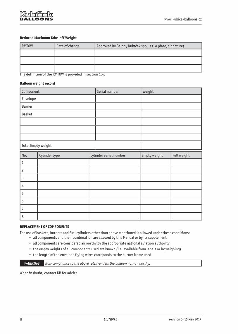
Reduced Maximum Take-off Weight
RMTOW Date of change Approved by Balóny Kubíček spol. s r. o (date, signature)
The definition of the RMTOW is provided in section 1.4.
Balloon weight record
Component Serial number Weight
Envelope
Burner
Basket
Total Empty Weight
No. Cylinder type Cylinder serial number Empty weight Full weight
1
2
3
4
5
6
7
8
REPLACEMENT OF COMPONENTS
The use of baskets, burners and fuel cylinders other than above mentioned is allowed under these conditions:• all components and their combination are allowed by this Manual or by its supplement
• all components are considered airworthy by the appropriate national aviation authority
• the empty weights of all components used are known (i.e. available from labels or by weighing)
• the length of the envelope flying wires correponds to the burner frame used
WARNING Non-compliance to the above rules renders the balloon non-airworthy.
When in doubt, contact KB for advice.
B.3102 Flight Manual
revision 2, 10 January 2018 >> EDITION 3 << III>> EDITION 3 <<
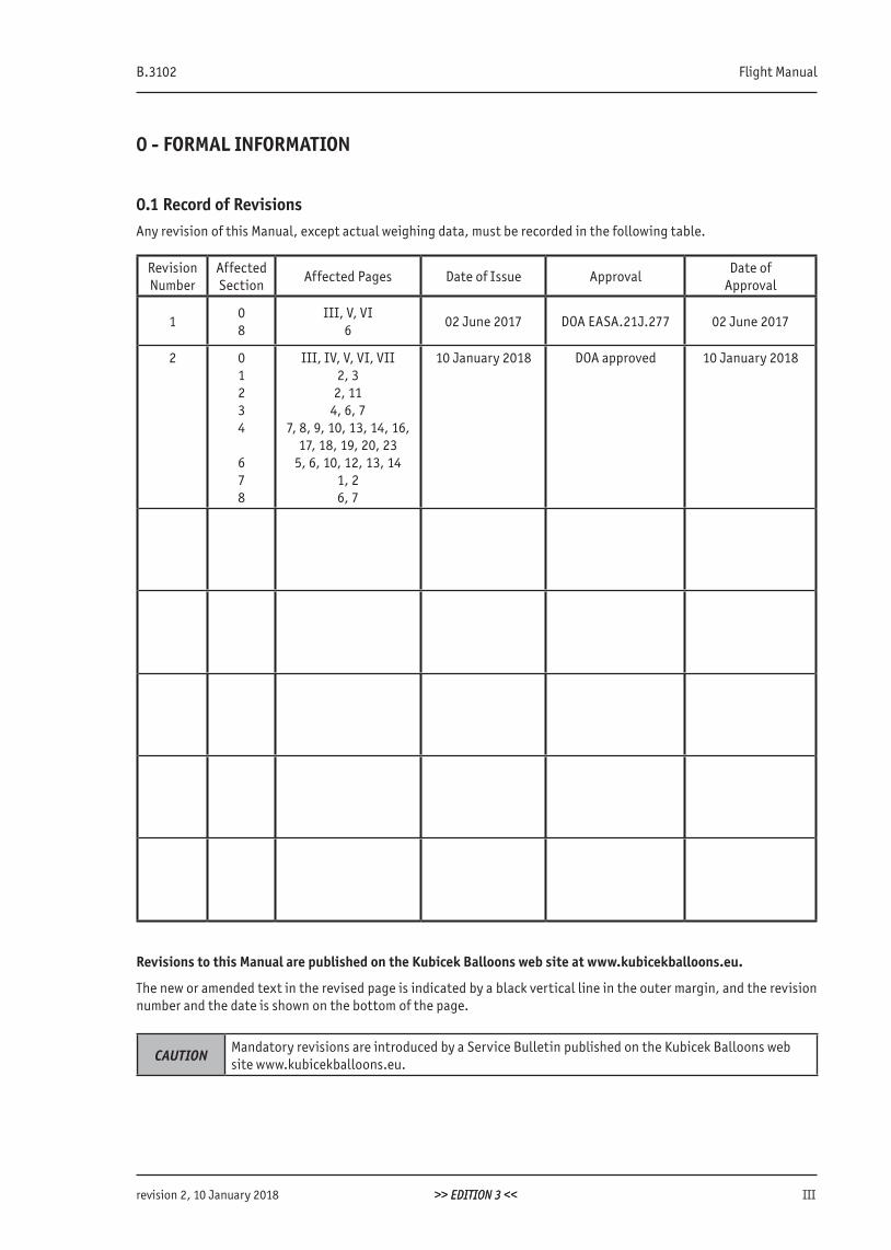
0 - FORMAL INFORMATION
0.1 Record of RevisionsAny revision of this Manual, except actual weighing data, must be recorded in the following table.
Revision Number
Affected Section
Affected Pages Date of Issue ApprovalDate of
Approval
108
III, V, VI6
02 June 2017 DOA EASA.21J.277 02 June 2017
2 01234
678
III, IV, V, VI, VII2, 3
2, 114, 6, 7
7, 8, 9, 10, 13, 14, 16, 17, 18, 19, 20, 23
5, 6, 10, 12, 13, 141, 26, 7
10 January 2018 DOA approved 10 January 2018
Revisions to this Manual are published on the Kubicek Balloons web site at www.kubicekballoons.eu.
The new or amended text in the revised page is indicated by a black vertical line in the outer margin, and the revision number and the date is shown on the bottom of the page.
CAUTION Mandatory revisions are introduced by a Service Bulletin published on the Kubicek Balloons website www.kubicekballoons.eu.
www.kubicekballoons.cz
IV EDITION 3 revision 2, 10 January 2018>> EDITION 3 <<
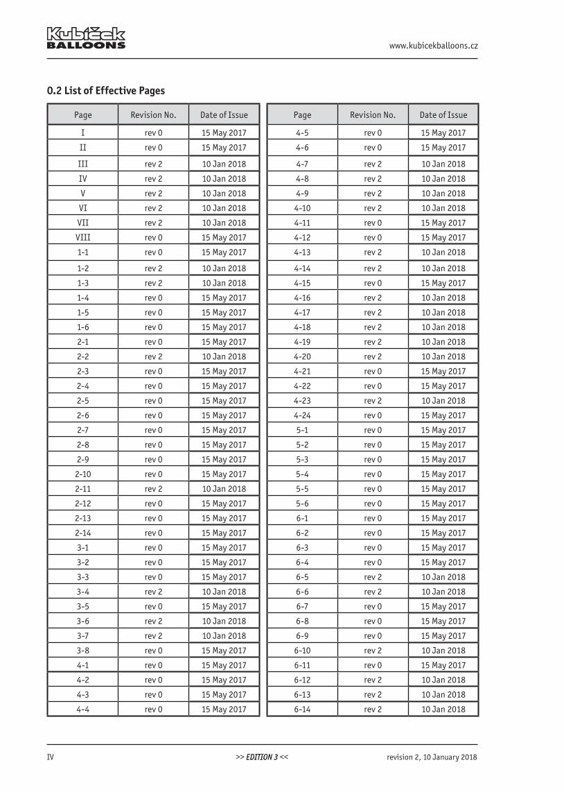
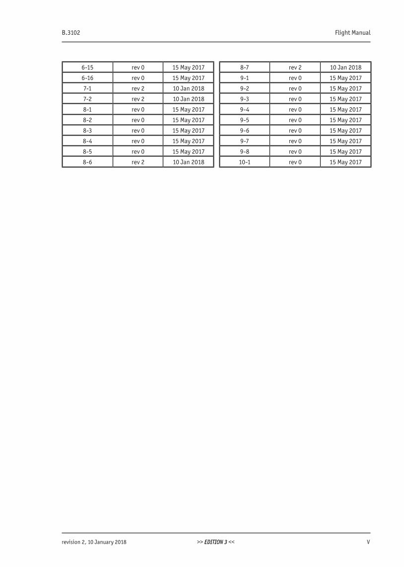
0.2 List of Effective Pages
Page Revision No. Date of Issue Page Revision No. Date of Issue
I rev 0 15 May 2017 4-5 rev 0 15 May 2017
II rev 0 15 May 2017 4-6 rev 0 15 May 2017
III rev 2 10 Jan 2018 4-7 rev 2 10 Jan 2018
IV rev 2 10 Jan 2018 4-8 rev 2 10 Jan 2018
V rev 2 10 Jan 2018 4-9 rev 2 10 Jan 2018
VI rev 2 10 Jan 2018 4-10 rev 2 10 Jan 2018
VII rev 2 10 Jan 2018 4-11 rev 0 15 May 2017
VIII rev 0 15 May 2017 4-12 rev 0 15 May 2017
1-1 rev 0 15 May 2017 4-13 rev 2 10 Jan 2018
1-2 rev 2 10 Jan 2018 4-14 rev 2 10 Jan 2018
1-3 rev 2 10 Jan 2018 4-15 rev 0 15 May 2017
1-4 rev 0 15 May 2017 4-16 rev 2 10 Jan 2018
1-5 rev 0 15 May 2017 4-17 rev 2 10 Jan 2018
1-6 rev 0 15 May 2017 4-18 rev 2 10 Jan 2018
2-1 rev 0 15 May 2017 4-19 rev 2 10 Jan 2018
2-2 rev 2 10 Jan 2018 4-20 rev 2 10 Jan 2018
2-3 rev 0 15 May 2017 4-21 rev 0 15 May 2017
2-4 rev 0 15 May 2017 4-22 rev 0 15 May 2017
2-5 rev 0 15 May 2017 4-23 rev 2 10 Jan 2018
2-6 rev 0 15 May 2017 4-24 rev 0 15 May 2017
2-7 rev 0 15 May 2017 5-1 rev 0 15 May 2017
2-8 rev 0 15 May 2017 5-2 rev 0 15 May 2017
2-9 rev 0 15 May 2017 5-3 rev 0 15 May 2017
2-10 rev 0 15 May 2017 5-4 rev 0 15 May 2017
2-11 rev 2 10 Jan 2018 5-5 rev 0 15 May 2017
2-12 rev 0 15 May 2017 5-6 rev 0 15 May 2017
2-13 rev 0 15 May 2017 6-1 rev 0 15 May 2017
2-14 rev 0 15 May 2017 6-2 rev 0 15 May 2017
3-1 rev 0 15 May 2017 6-3 rev 0 15 May 2017
3-2 rev 0 15 May 2017 6-4 rev 0 15 May 2017
3-3 rev 0 15 May 2017 6-5 rev 2 10 Jan 2018
3-4 rev 2 10 Jan 2018 6-6 rev 2 10 Jan 2018
3-5 rev 0 15 May 2017 6-7 rev 0 15 May 2017
3-6 rev 2 10 Jan 2018 6-8 rev 0 15 May 2017
3-7 rev 2 10 Jan 2018 6-9 rev 0 15 May 2017
3-8 rev 0 15 May 2017 6-10 rev 2 10 Jan 2018
4-1 rev 0 15 May 2017 6-11 rev 0 15 May 2017
4-2 rev 0 15 May 2017 6-12 rev 2 10 Jan 2018
4-3 rev 0 15 May 2017 6-13 rev 2 10 Jan 2018
4-4 rev 0 15 May 2017 6-14 rev 2 10 Jan 2018
B.3102 Flight Manual
revision 2, 10 January 2018 >> EDITION 3 << VEDITION 3
6-15 rev 0 15 May 2017 8-7 rev 2 10 Jan 2018
6-16 rev 0 15 May 2017 9-1 rev 0 15 May 2017
7-1 rev 2 10 Jan 2018 9-2 rev 0 15 May 2017
7-2 rev 2 10 Jan 2018 9-3 rev 0 15 May 2017
8-1 rev 0 15 May 2017 9-4 rev 0 15 May 2017
8-2 rev 0 15 May 2017 9-5 rev 0 15 May 2017
8-3 rev 0 15 May 2017 9-6 rev 0 15 May 2017
8-4 rev 0 15 May 2017 9-7 rev 0 15 May 2017
8-5 rev 0 15 May 2017 9-8 rev 0 15 May 2017
8-6 rev 2 10 Jan 2018 10-1 rev 0 15 May 2017
www.kubicekballoons.cz
VI EDITION 3 revision 2, 10 January 2018>> EDITION 3 <<
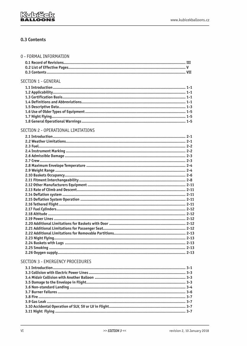
0.3 Contents
0 - FORMAL INFORMATION0.1 Record of Revisions...................................................................................................... III0.2 List of Effective Pages .................................................................................................. V0.3 Contents .................................................................................................................... VII
SECTION 1 - GENERAL1.1 Introduction ............................................................................................................... 1-11.2 Applicability ............................................................................................................... 1-11.3 Certification Basis ....................................................................................................... 1-11.4 Definitions and Abbreviations ....................................................................................... 1-11.5 Descriptive Data .......................................................................................................... 1-31.6 Use of Older Types of Equipment .................................................................................... 1-51.7 Night Flying ................................................................................................................ 1-51.8 General Operational Warnings ....................................................................................... 1-5
SECTION 2 - OPERATIONAL LIMITATIONS2.1 Introduction ............................................................................................................... 2-12.2 Weather Limitations .................................................................................................... 2-12.3 Fuel ........................................................................................................................... 2-22.4 Instrument Marking .................................................................................................... 2-22.6 Admissible Damage ..................................................................................................... 2-32.7 Crew .......................................................................................................................... 2-32.8 Maximum Envelope Temperature ................................................................................... 2-42.9 Weight Range ............................................................................................................. 2-42.10 Baskets Occupancy ..................................................................................................... 2-62.11 Fitment Interchangeability ......................................................................................... 2-82.12 Other Manufacturers Equipment .................................................................................. 2-112.13 Rate of Climb and Descent ........................................................................................... 2-112.14 Deflation system ....................................................................................................... 2-112.15 Deflation System Operation ........................................................................................ 2-112.16 Tethered Flight .......................................................................................................... 2-112.17 Fuel Cylinders ............................................................................................................ 2-122.18 Altitude ................................................................................................................... 2-122.19 Power Lines .............................................................................................................. 2-122.20 Additional Limitations for Baskets with Door ................................................................ 2-122.21 Additional Limitations for Passenger Seat ..................................................................... 2-122.22 Additional Limitations for Removable Partitions ............................................................ 2-132.23 Night Flying .............................................................................................................. 2-132.24 Baskets with Lugs ..................................................................................................... 2-132.25 Smoking .................................................................................................................. 2-132.26 Oxygen supply ........................................................................................................... 2-13
SECTION 3 - EMERGENCY PROCEDURES3.1 Introduction ............................................................................................................... 3-13.3 Collision with Electric Power Lines ................................................................................. 3-33.4 Midair Collision with Another Balloon ............................................................................ 3-33.5 Damage to the Envelope in Flight ................................................................................... 3-33.6 Non-standard Landing ................................................................................................. 3-43.7 Burner Failures ........................................................................................................... 3-63.8 Fire ........................................................................................................................... 3-73.9 Gas Leak .................................................................................................................... 3-73.10 Accidental Operation of SLV, SV or LV in Flight ................................................................ 3-73.11 Night Flying ............................................................................................................. 3-7
B.3102 Flight Manual
revision 2, 10 January 2018 >> EDITION 3 << VIIEDITION 3
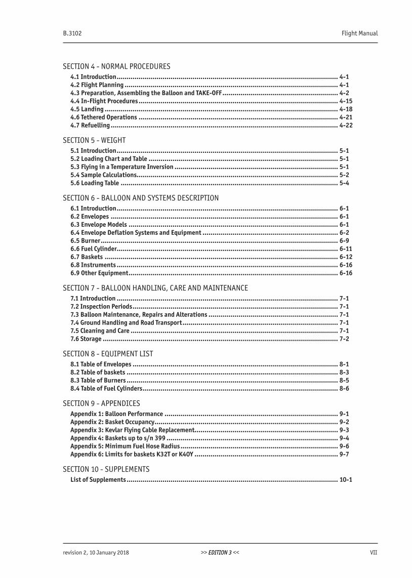
SECTION 4 - NORMAL PROCEDURES4.1 Introduction ............................................................................................................... 4-14.2 Flight Planning ........................................................................................................... 4-14.3 Preparation, Assembling the Balloon and TAKE-OFF .......................................................... 4-24.4 In-Flight Procedures .................................................................................................... 4-154.5 Landing ..................................................................................................................... 4-184.6 Tethered Operations .................................................................................................... 4-214.7 Refuelling .................................................................................................................. 4-22
SECTION 5 - WEIGHT5.1 Introduction ............................................................................................................... 5-15.2 Loading Chart and Table ............................................................................................... 5-15.3 Flying in a Temperature Inversion .................................................................................. 5-15.4 Sample Calculations..................................................................................................... 5-25.6 Loading Table ............................................................................................................. 5-4
SECTION 6 - BALLOON AND SYSTEMS DESCRIPTION6.1 Introduction ............................................................................................................... 6-16.2 Envelopes .................................................................................................................. 6-16.3 Envelope Models ......................................................................................................... 6-16.4 Envelope Deflation Systems and Equipment .................................................................... 6-26.5 Burner ....................................................................................................................... 6-96.6 Fuel Cylinder............................................................................................................... 6-116.7 Baskets ..................................................................................................................... 6-126.8 Instruments ............................................................................................................... 6-166.9 Other Equipment ......................................................................................................... 6-16
SECTION 7 - BALLOON HANDLING, CARE AND MAINTENANCE 7.1 Introduction ............................................................................................................... 7-17.2 Inspection Periods ....................................................................................................... 7-17.3 Balloon Maintenance, Repairs and Alterations ................................................................. 7-17.4 Ground Handling and Road Transport .............................................................................. 7-17.5 Cleaning and Care ........................................................................................................ 7-17.6 Storage ...................................................................................................................... 7-2
SECTION 8 - EQUIPMENT LIST 8.1 Table of Envelopes ....................................................................................................... 8-18.2 Table of baskets .......................................................................................................... 8-38.3 Table of Burners .......................................................................................................... 8-58.4 Table of Fuel Cylinders .................................................................................................. 8-6
SECTION 9 - APPENDICESAppendix 1: Balloon Performance ....................................................................................... 9-1Appendix 2: Basket Occupancy ............................................................................................ 9-2Appendix 3: Kevlar Flying Cable Replacement........................................................................ 9-3Appendix 4: Baskets up to s/n 399 ...................................................................................... 9-4Appendix 5: Minimum Fuel Hose Radius ............................................................................... 9-6Appendix 6: Limits for baskets K32T or K40Y ........................................................................ 9-7
SECTION 10 - SUPPLEMENTSList of Supplements .......................................................................................................... 10-1

www.kubicekballoons.cz
VIII EDITION 3 revision 0, 15 May 2017
INTENTIONALLY LEFT BLANK
>> EDITION 3 <<
B.3102 Flight Manual
revision 0, 15 May 2017 >> EDITION 3 << 1-1
SECTION 1 - GENERAL
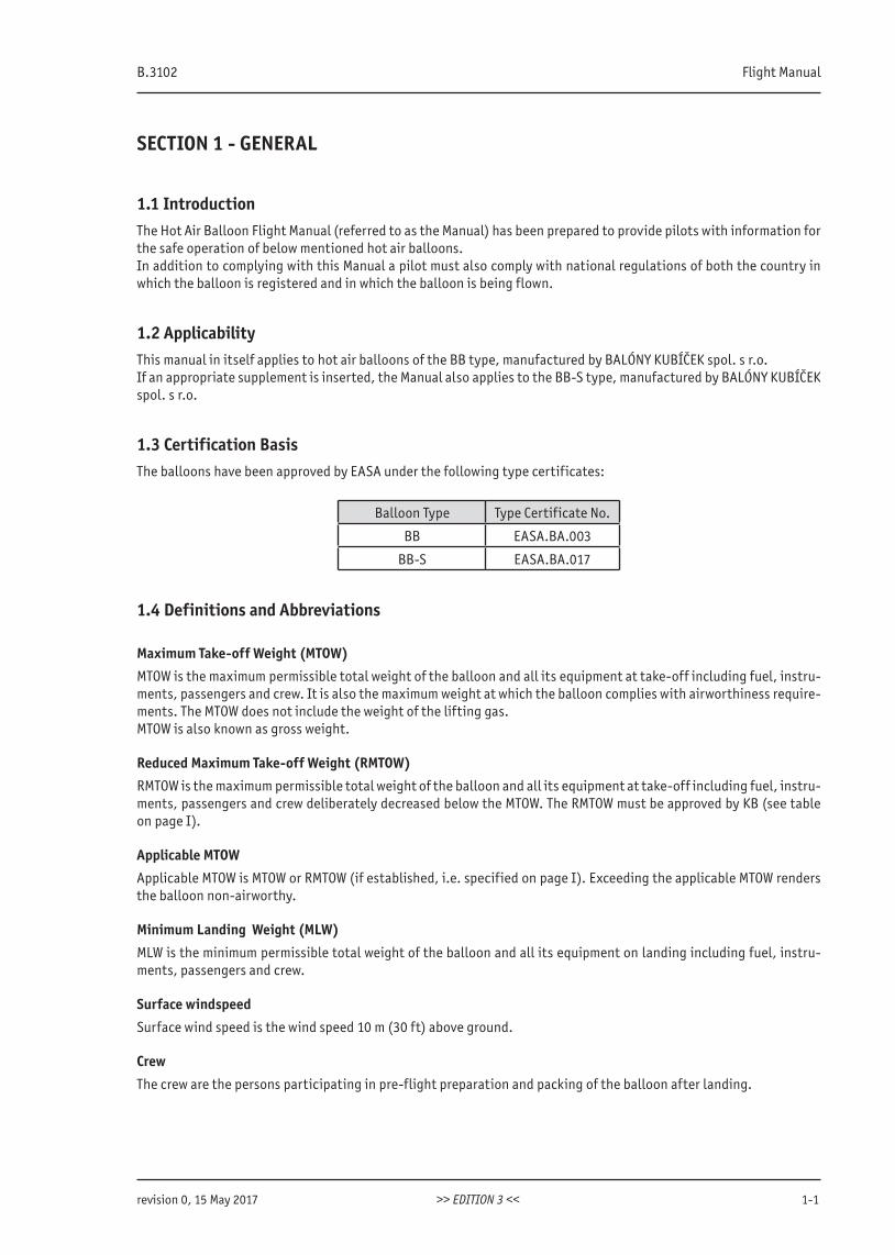
1.1 IntroductionThe Hot Air Balloon Flight Manual (referred to as the Manual) has been prepared to provide pilots with information for the safe operation of below mentioned hot air balloons.In addition to complying with this Manual a pilot must also comply with national regulations of both the country in which the balloon is registered and in which the balloon is being flown.
1.2 ApplicabilityThis manual in itself applies to hot air balloons of the BB type, manufactured by BALÓNY KUBÍČEK spol. s r.o.If an appropriate supplement is inserted, the Manual also applies to the BB-S type, manufactured by BALÓNY KUBÍČEK spol. s r.o.
1.3 Certification BasisThe balloons have been approved by EASA under the following type certificates:
Balloon Type Type Certificate No.
BB EASA.BA.003
BB-S EASA.BA.017
1.4 Definitions and Abbreviations
Maximum Take-off Weight (MTOW)
MTOW is the maximum permissible total weight of the balloon and all its equipment at take-off including fuel, instru-ments, passengers and crew. It is also the maximum weight at which the balloon complies with airworthiness require-ments. The MTOW does not include the weight of the lifting gas.MTOW is also known as gross weight.
Reduced Maximum Take-off Weight (RMTOW)
RMTOW is the maximum permissible total weight of the balloon and all its equipment at take-off including fuel, instru-ments, passengers and crew deliberately decreased below the MTOW. The RMTOW must be approved by KB (see table on page I).
Applicable MTOW
Applicable MTOW is MTOW or RMTOW (if established, i.e. specified on page I). Exceeding the applicable MTOW renders the balloon non-airworthy.
Minimum Landing Weight (MLW)
MLW is the minimum permissible total weight of the balloon and all its equipment on landing including fuel, instru-ments, passengers and crew.
Surface windspeed
Surface wind speed is the wind speed 10 m (30 ft) above ground.
Crew
The crew are the persons participating in pre-flight preparation and packing of the balloon after landing.
www.kubicekballoons.cz
1-2 EDITION 3 revision 2, 10 January 2018
Chase Crew
The Chase Crew are the persons following the balloon in the chase vehicle.
Passenger
A passenger is a person aboard the balloon not involved in controlling it.
Total Permitted Lift
The total permitted lift is the maximum lift that the balloon is capable of with regard to ambient conditions.
Abbreviations:
ISA - International Standard Atmosphere KB - BALÓNY KUBÍČEK spol. s r.o. DS - Deflation System FDS - Fast Deflation System LV - Lite Vent SV - Smart Vent SLV - Slide Vent RV - Rotation Vent MB - Main Burner WB - Whisper Burner PF - Pilot Flame Throughout this Manual the terms mass and weight are interchangeable and have an identical meaning.
The following definitions apply to Warnings, Cautions and Notes used in the Manual:
WARNING Means that the non-observation of the corresponding procedure leads to an immediate or important degradation of the operational safety which may result in severe personal injury or death.
CAUTION Means that the non-observation of the corresponding procedure leads to a minor or to a more or less long term degradation of the flight safety.
NOTE Draws the attention to any special item not directly related to safety but which is important or unusual.
B.3102 Flight Manual
revision 2, 10 January 2018 >> EDITION 3 << 1-3
1.5 Descriptive DataA hot air balloon is a very simple aircraft that derives its lift from the heated air. It consists of these major parts:
• envelope - the body containing the medium which provides the lift
• basket - the container suspended beneath the envelope for the carriage of the balloon occupants
• heater system - the system used to heat the air to provide the lifting means of the balloon. The system inclu-des the heat source (burner), controls, fuel hoses, fuel cylinders, regulator, control valves and other related elements.
A complete description of the balloon, its components, systems and controls is given in chapter 6.
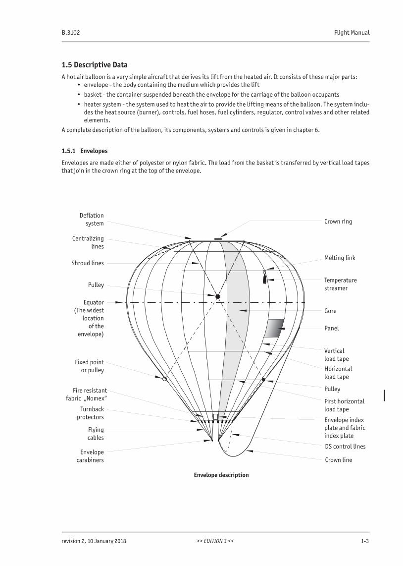
1.5.1 Envelopes
Envelopes are made either of polyester or nylon fabric. The load from the basket is transferred by vertical load tapes that join in the crown ring at the top of the envelope.
Centralizinglines
Shroud lines
Pulley
Equator(The widest
locationof the
envelope)
Fixed pointor pulley
Fire resistant fabric „Nomex“
Turnbackprotectors
Flyingcables
Envelopecarabiners
Envelope description
Deflationsystem Crown ring
Melting link
Temperaturestreamer
Gore
Panel
Verticalload tape
Horizontalload tape
Pulley
First horizontalload tape
Envelope index plate and fabric index plate
DS control lines
Crown line
www.kubicekballoons.cz
1-4 EDITION 3 revision 0, 15 May 2017
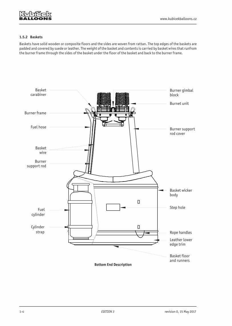
1.5.2 Baskets
Baskets have solid wooden or composite floors and the sides are woven from rattan. The top edges of the baskets are padded and covered by suede or leather. The weight of the basket and contents is carried by basket wires that runfrom the burner frame through the sides of the basket under the floor of the basket and back to the burner frame.
Burner frame
Basketcarabiner
Fuel hose
Basketwire
Fuelcylinder
Cylinderstrap
Bottom End Description
Burnet unit
Burner gimbal block
Burner support rod cover
Basket wickerbody
Step hole
Rope handles
Leather loweredge trim
Basket floorand runners
Burnersupport rod
B.3102 Flight Manual
revision 0, 15 May 2017 >> EDITION 3 << 1-5
1.5.3 Burners
Burners are the power source of a balloon. Fuel is taken from the fuel cylinders through fuel hoses and burnt to heat the air within the balloon envelope.
1.5.4 Fuel Cylinders
Fuel is stored in liquid form within fuel cylinders that are strapped within the basket. Each cylinder has a content gauge and a liquid take-off through which fuel is supplied to the burner. In addition master cylinders have a vapor take-off that supplies fuel to vapor pilot lights if required.
1.6 Use of Older Types of EquipmentOlder types of baskets and burners not listed in this Manual may be used with new balloon envelopes provided the appropriate supplement to this Manual is used.
1.7 Night Flying
National rules for balloon night flying differ from country to country. Additional requirements or ones different from those stated in this Manual or in its supplement may apply.
1.8 General Operational Warnings
WARNING Improper operation of the balloon may result in injury or death.
Power Lines
Power lines represent a major source of danger in ballooning. Their dangers cannot be overstated and must be treated with the greatest respect at all times. Some of the consequences of inadvertent power line contact include: 1. fire, 2. electrocution, 3. ruptures of the fuel system, 4. cutting of load cables, 5. severe damage to fabric. Each of these dangers or damage represents immediate life threatening situations and must be avoided.
Licensed Pilots
The only licensed pilots may serve as a pilot in command. The pilot in command is responsible for the safe and proper conduct of all phases of flight. he or she must make the final decision on weather conditions, launch flight hazards, aircraft airworthiness, the execution of correct emergency procedures, the care of passengers, and landing site selection as well as any other situation which might effect the safe conclusion of flight. The pilot in command must have read and understand this manual and thoroughly and comply with all applicable requirements.If in doubt, contact KB for advice.
Fuel
LP gas or propane is a highly volatile fuel and as such must be treated with a great deal of respect at all times. Leaking LP gas in contact with skin can create severe burns. Liquid petroleum gas of which propane is the most common constituent, is heavier than air and as such tends to collect in low areas. It can pose a great danger of explosion. Similarly, any leak may be ignited by an ignition source at several feet distance. It is imperative that the potential for leaks be minimized, and when they occur, rapid and positive action must be taken to prevent a dangerous and possibly uncontrollable fire.
Fire
Fire represents the most dangerous and immediate life threatening situation in flight. Due to limited means of extinguishing the fire, it is imperative that rapid steps be taken to land the aircraft immediately. Panic must be avoided and the pilot in command must control the action for all occupants. The option of jumping holds little chance for survival at heights much above 20 feet and further lessens the chance of survival of remaining occupants. Once the balloon has landed, all passengers and crew must exit the craft simultaneously to preclude the further flight with anyone left aboard.
www.kubicekballoons.cz
1-6 EDITION 3 revision 0, 15 May 2017
Limited Controllability
Limited controllability of a balloons in relation to other aircraft makes it mandatory that balloons remain clear of high density air traffic, high performance and military aircraft operating areas as well as marginal visibility conditions. Balloons produce faint and unreliable radar returns (unless equipped with a portable transponder) for both ground controllers and airborne radars leaving visual observation as the only means of locating and avoiding airborne balloons.To fly in a controlled airspace or military areas requires a clearance from the responsible ATC/controller. If a transpponder is required, the balloon must be equipped with it.
Mid-air Collision
Avoid mid-air collision with any other balloon/aircraft at all times.
NOTE Envelope to envelope contact in approximate level flight creates low risk. Both pilots must take action to separate
WARNING Envelope - basket contact creates high risk for both the balloons. Both pilots must take all possible mea-sures to avoid such a collision. Both pilots must take action to separate
Fast Climb
The pilot must make sure that the sky above is clear before he starts climbing at a speed higher than 1 m/s (200 ft/min). Otherwise there is a serious danger of collision due to significant lag the balloon takes to get back to horizontal flight.
Low Visibility
Flying at low visibility or with the possibility of restricted visibility, less than 1 NM, creates a high risk for the occu-pants and has to be avoided in any case.
Balloon Modification
DO NOT, under any circumstances, attempt to bypass, shortcut, or eliminate any operational or safety feature designed into this balloon system.
WARNING
The balloon must not be flown or modified without a valid approval of the appropriate national aviation authority.Hazardous conditions which could result in injury or death may result from:
• the installation of non-approved parts or materials• modification of any part• improper repair procedures
Before undertaking any maintenance or modification not specifically documented in the Maintenance Manual, con-tact BALÓNY KUBÍČEK spol. s r.o. (see the last page of this Manual).
B.3102 Flight Manual
revision 0, 15 May 2017 >> EDITION 3 << 2-1
SECTION 2 - OPERATIONAL LIMITATIONS
2.1 IntroductionThis section specifies the operational limitations for the balloon and its standard equipment.
WARNING The following limitations must be strictly adhered to, during the entire operation of the balloon.
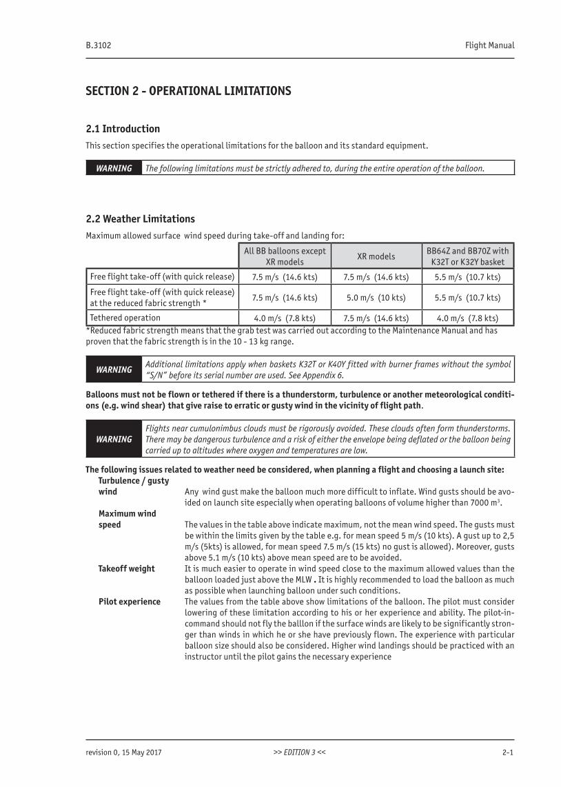
2.2 Weather LimitationsMaximum allowed surface wind speed during take-off and landing for:
All BB balloons except XR models
XR modelsBB64Z and BB70Z with
K32T or K32Y basket
Free flight take-off (with quick release) 7.5 m/s (14.6 kts) 7.5 m/s (14.6 kts) 5.5 m/s (10.7 kts)
Free flight take-off (with quick release) at the reduced fabric strength *
7.5 m/s (14.6 kts) 5.0 m/s (10 kts) 5.5 m/s (10.7 kts)
Tethered operation 4.0 m/s (7.8 kts) 7.5 m/s (14.6 kts) 4.0 m/s (7.8 kts)*Reduced fabric strength means that the grab test was carried out according to the Maintenance Manual and hasproven that the fabric strength is in the 10 - 13 kg range.
WARNING Additional limitations apply when baskets K32T or K40Y fitted with burner frames without the symbol “S/N” before its serial number are used. See Appendix 6.
Balloons must not be flown or tethered if there is a thunderstorm, turbulence or another meteorological conditi-ons (e.g. wind shear) that give raise to erratic or gusty wind in the vicinity of flight path.
WARNINGFlights near cumulonimbus clouds must be rigorously avoided. These clouds often form thunderstorms. There may be dangerous turbulence and a risk of either the envelope being deflated or the balloon being carried up to altitudes where oxygen and temperatures are low.
The following issues related to weather need be considered, when planning a flight and choosing a launch site: Turbulence / gusty wind Any wind gust make the balloon much more difficult to inflate. Wind gusts should be avo-
ided on launch site especially when operating balloons of volume higher than 7000 m3. Maximum wind speed The values in the table above indicate maximum, not the mean wind speed. The gusts must
be within the limits given by the table e.g. for mean speed 5 m/s (10 kts). A gust up to 2,5 m/s (5kts) is allowed, for mean speed 7.5 m/s (15 kts) no gust is allowed). Moreover, gusts above 5.1 m/s (10 kts) above mean speed are to be avoided.
Takeoff weight It is much easier to operate in wind speed close to the maximum allowed values than the balloon loaded just above the MLW . It is highly recommended to load the balloon as much as possible when launching balloon under such conditions.
Pilot experience The values from the table above show limitations of the balloon. The pilot must consider lowering of these limitation according to his or her experience and ability. The pilot-in-command should not fly the balllon if the surface winds are likely to be significantly stron-ger than winds in which he or she have previously flown. The experience with particular balloon size should also be considered. Higher wind landings should be practiced with an instructor until the pilot gains the necessary experience
www.kubicekballoons.cz
2-2 EDITION 3 revision 2, 10 January 2018
WARNING
Gusty winds or turbulence on launch site can cause tipping of the basket on the short side. This can cause a serious injury to passengers in the basket. The probability of a basket tipping is increased with a balloon less loaded. Take off in winds with a speed 5.0 m/s (10 kts) and higher makes the controllability of the balloon difficult.
2.3 FuelThe approved fuel is either propane or a propane-butane mix (LPG).Maximum admissible fuel pressure: 12 bar (174 psi)When pressurising fuel cylinders with nitrogen, care must be taken not to exceed 10 bar (145 psi).Minimum admissible fuel pressure: 3 bar (44 psi)
WARNING Fuel cylinders must not be heated by a direct flame or left in direct sunshine or overfilled.
CAUTION
Care should be taken if the fuel pressure is below 5.5bar (80 psi) which reduces heat output ofthe burner. At low fuel pressure a balloon will be less responsive. The bigger the envelope thestronger this effect is. It is advisable to heat with both main and whisper burner tocompensate for the decreased heat output.
NOTE The pressure in a cylinder will be reduced if it has been pressurized with nitrogen as the contents of the cylinder is reduced. Pilot flame failure may occur when nitrogen is used.
At high burner pressures the burner flame will be longer than usual. In smaller envelopes (up to 3400 m3) care must be taken to avoid damage to the control lines if the burner was operated with longer bursts.
Minimum Fuel Quantity
The minimum number of full fuel cylinders required at take-off:
1-unit burner 2 cylinders
2-unit burner 2 cylinders
3-unit burner 3 cylinders
4-unit burner 4 cylinders
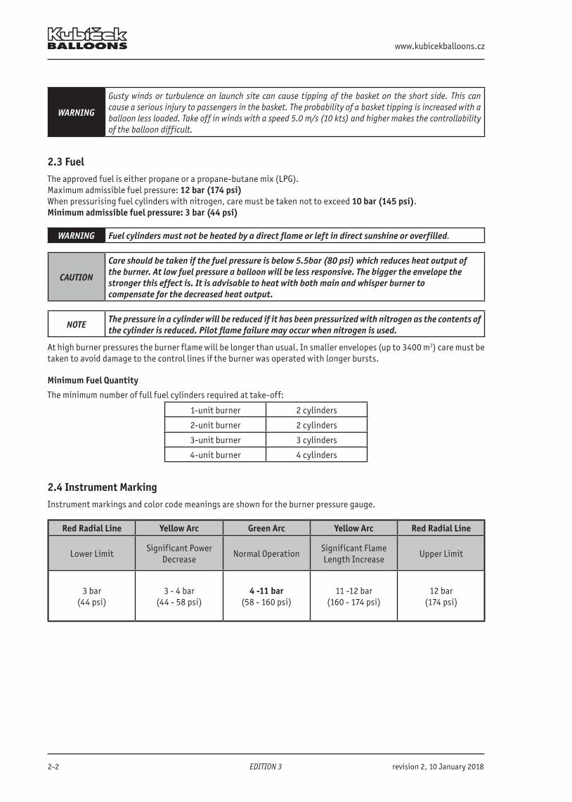
2.4 Instrument MarkingInstrument markings and color code meanings are shown for the burner pressure gauge.
Red Radial Line Yellow Arc Green Arc Yellow Arc Red Radial Line
Lower LimitSignificant Power
Decrease Normal Operation
Significant Flame Length Increase
Upper Limit
3 bar(44 psi)
3 - 4 bar(44 - 58 psi)
4 -11 bar(58 - 160 psi)
11 -12 bar(160 - 174 psi)
12 bar(174 psi)
B.3102 Flight Manual
revision 0, 15 May 2017 >> EDITION 3 << 2-3
2.5 Minimum EquipmentThe following list of equipment must be carried on every flight:
• Altimeter and variometer
• Envelope temperature indicator. This may be either one that gives a direct reading or one that gives a warning signal (temperature streamer attached with a melting link).
• Two sources of ignition. Matches or ignitor or similar source in addition to piezo ignitors built into the burner.
• Fire extinguisher.
• Fire blanket.
• Drop line of length at least 25m (82 ft).
• An accurate time piece displaying time in hours, minutes and seconds.
• Items used to determine drift direction (e.g. compass, map...)
• Knife.
• First aid kit.
• Protective gloves for the pilot and crew.
• Oxygen supply (supplemental oxygen storage and dispensing apparatus) for high altitudes flights - see 2.26
WARNINGProlonged flight above 3 000m (10 000 ft) MSL without oxygen may result in oxygen deficiencies cau-sing hypoxia. Symptoms are loss of coordination, dizziness, blurred vision, or an euphoric feeling. Hypo-xia may eventually cause unconsciousness and death.
WARNING National regulations may require additional equipment based on conditions of the intended flight!
WARNING All required minimum equipment must be of proper and quality design and must function correctly!
CAUTION If the maximum permitted envelope temperature is lower than 124°C (255°F) the thermometer is to be used for monitoring envelope fabric temperature instead of temperatue streamer.
2.6 Admissible Damage• No damage is permitted to the burner or fuel system, and no damage is permitted to the load tapes or to any
load bearing part of the envelope or basket suspension system.
• Damage to the fabric below the first horizontal load tape (except D, ED types) or within 4 m (13 ft) of the nomex (D, ED type) is permitted.
• Damage to fabric above the previously described location is limited to small holes or tears of no more than 5mm (1/4 in) in any direction. The integrity of any panel must not be affected by the holes or tears .
• Any damage exceeding the above limits must be repaired prior the next flight according to the instructions given by the Kubicek Balloons Maintenance Manual.
WARNINGAny damage to the fabric weakens the fabric‘s resistance to tear and causes localized heating of the fabric around that damage. Damage exceeding those listed above increases the potential of propagating a tear or hole and is unacceptable for flight.
• The balloon must not be flown without the basket support rods.
• The fuel quantity gauge must function correctly at least on the minimum number of full fuel cylinders requi-red at take-off (see chapter 2.3).
2.7 CrewMinimum crew: One pilot holding a valid appropriate license.Maximum basket occupancy: See 2.9 and 2.10 below.
www.kubicekballoons.cz
2-4 EDITION 3 revision 0, 15 May 2017
2.8 Maximum Envelope TemperatureThe maximum allowable temperature in the envelope:
• 124°C (255°F) for the envelopes entirely made from Polyester fabric
• specified on the Envelope fabric index plate for other fabrics
The envelope fabric index plate is located at the envelope mouth.
CAUTIONOperating above these limits can cause a rapid decrease of the fabric strength and porosity of the enve-lope fabric.
2.9 Weight RangeThe actual weigth of the balloon must be kept between the following limits during the entire flight:
Upper limit - the lowest of these values: Lower limit
MTOW or,
RMTOW (if established), or
Maximum balloon lifting capacity established according to chapter 5 of this Manual
MLW
CAUTIONIf a balloon is flown very lightly loaded then there will be a relatively low pressure in the envelope and it will distort easily in either light turbulence or when passing through wind shear in the climb or descent. This mainly concerns smaller balloons.
CAUTION Flying at temperatures 115°C and higher in the envelope results in increased fuel consumption.
RMTOW limitations
The owner/operator of a balloon may, by agreement with KB, designate a RMTOW for a specific balloon which is lower than the MTOW for the specific balloon model. This RMTOW must not be less than 55% of the original MTOW or the sum of weight of a complete balloon with a minimum crew and a minimum equipment, whichever is greater. The RMTOW, if applied, is specified on page I of this Manual.The RMTOW may be revised at any time by agreement with KB. Any revision becomes valid when the revised figure is entered on page I of this Manual and countersigned by KB.
B.3102 Flight Manual
revision 0, 15 May 2017 >> EDITION 3 << 2-5
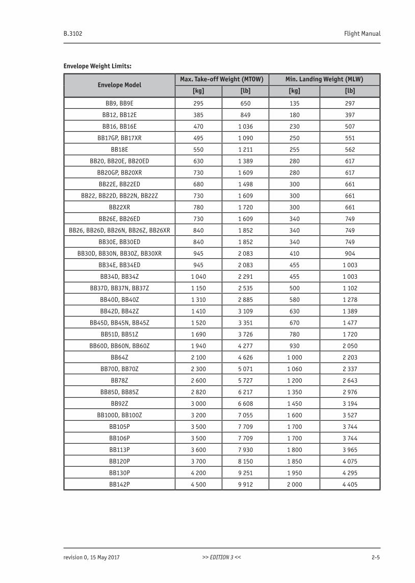
Envelope Weight Limits:
Envelope ModelMax. Take-off Weight (MTOW) Min. Landing Weight (MLW)
[kg] [lb] [kg] [lb]
BB9, BB9E 295 650 135 297
BB12, BB12E 385 849 180 397
BB16, BB16E 470 1 036 230 507
BB17GP, BB17XR 495 1 090 250 551
BB18E 550 1 211 255 562
BB20, BB20E, BB20ED 630 1 389 280 617
BB20GP, BB20XR 730 1 609 280 617
BB22E, BB22ED 680 1 498 300 661
BB22, BB22D, BB22N, BB22Z 730 1 609 300 661
BB22XR 780 1 720 300 661
BB26E, BB26ED 730 1 609 340 749
BB26, BB26D, BB26N, BB26Z, BB26XR 840 1 852 340 749
BB30E, BB30ED 840 1 852 340 749
BB30D, BB30N, BB30Z, BB30XR 945 2 083 410 904
BB34E, BB34ED 945 2 083 455 1 003
BB34D, BB34Z 1 040 2 291 455 1 003
BB37D, BB37N, BB37Z 1 150 2 535 500 1 102
BB40D, BB40Z 1 310 2 885 580 1 278
BB42D, BB42Z 1 410 3 109 630 1 389
BB45D, BB45N, BB45Z 1 520 3 351 670 1 477
BB51D, BB51Z 1 690 3 726 780 1 720
BB60D, BB60N, BB60Z 1 940 4 277 930 2 050
BB64Z 2 100 4 626 1 000 2 203
BB70D, BB70Z 2 300 5 071 1 060 2 337
BB78Z 2 600 5 727 1 200 2 643
BB85D, BB85Z 2 820 6 217 1 350 2 976
BB92Z 3 000 6 608 1 450 3 194
BB100D, BB100Z 3 200 7 055 1 600 3 527
BB105P 3 500 7 709 1 700 3 744
BB106P 3 500 7 709 1 700 3 744
BB113P 3 600 7 930 1 800 3 965
BB120P 3 700 8 150 1 850 4 075
BB130P 4 200 9 251 1 950 4 295
BB142P 4 500 9 912 2 000 4 405
www.kubicekballoons.cz
2-6 EDITION 3 revision 0, 15 May 2017
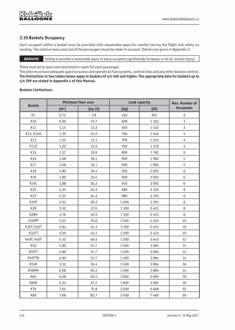
2.10 Baskets OccupancyEach occupant within a basket must be provided with reasonable space for comfort during the flight and safety on landing. The relative mass and size of the passengers must be taken in account. Details are given in Appendix 2.
WARNING Failing to provide a reasonable space to every occupant significantly increases a risk of serious injury!
There must be at least one hand hold in reach for each passenger.The pilot must have adequate space to access and operate all fuel systems, control lines and any other balloon control.The limitations in two tables below apply to baskets of s/n 400 and higher. The appropriate data for baskets up tos/n 399 are stated in Appendix 4 of this Manual.
Baskets Limitations:
BasketMinimum floor area Load capacity Max. Number of
Occupants[m2] [sq. ft] [kg] [lb]
K7 0.72 7.8 450 991 2
K10 0.99 10.7 600 1 322 3
K11 1.14 12.2 650 1 432 3
K12, K12A 1.35 14.5 700 1 542 4
K13 1.22 13.1 700 1 542 4
K13S 1,20 12,9 550 1 210 3
K15 1.57 16.9 800 1 762 5
K16 1.68 18.1 900 1 982 5
K17 1.68 18.1 900 1 982 5
K18 1.80 19.4 950 2 093 6
K19 1.80 19.4 950 2 093 6
K19L 1.88 20.2 950 2 093 6
K22 2.25 24.2 980 2 159 8
K23 2.25 24.2 980 2 159 6
K25P 2.62 28.2 1 000 2 203 8
K28 3.52 37.9 1 100 2 423 8
K28H 3.76 40.5 1 100 2 423 8
K30PP 3.25 35.0 1 100 2 423 10
K32Y, K32T 3.84 41.3 1 100 2 423 10
K32TT 4.00 43.1 1 100 2 423 10
K40Y, K40T 4.32 46.5 1 200 2 643 12
K50 4.80 51.7 1 400 3 084 14
K50TT 4.80 51.7 1 400 3 084 14
K50TT8 4.80 51.7 1 400 3 084 14
K55X 5.52 59.4 1 400 3 084 16
K58HH 6.08 65.4 1 400 3 084 14
K60 6.08 65.4 1 800 3 965 18
K60X 6.24 67.2 1 800 3 965 18
K70 7.04 75.8 3 000 6 608 22
K80 7.68 82.7 3 400 7 489 26
B.3102 Flight Manual
revision 0, 15 May 2017 >> EDITION 3 << 2-7
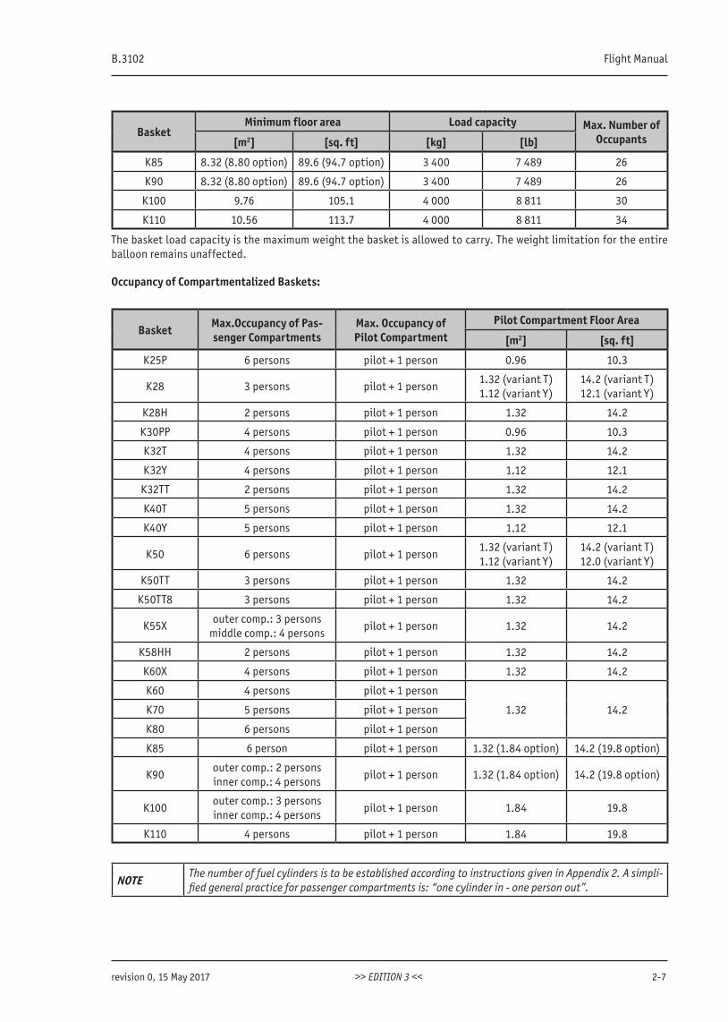
BasketMinimum floor area Load capacity Max. Number of
Occupants[m2] [sq. ft] [kg] [lb]
K85 8.32 (8.80 option) 89.6 (94.7 option) 3 400 7 489 26
K90 8.32 (8.80 option) 89.6 (94.7 option) 3 400 7 489 26
K100 9.76 105.1 4 000 8 811 30
K110 10.56 113.7 4 000 8 811 34
The basket load capacity is the maximum weight the basket is allowed to carry. The weight limitation for the entire balloon remains unaffected.
Occupancy of Compartmentalized Baskets:
Basket Max.Occupancy of Pas-senger Compartments
Max. Occupancy of Pilot Compartment
Pilot Compartment Floor Area
[m2] [sq. ft]
K25P 6 persons pilot + 1 person 0.96 10.3
K28 3 persons pilot + 1 person1.32 (variant T)1.12 (variant Y)
14.2 (variant T)12.1 (variant Y)
K28H 2 persons pilot + 1 person 1.32 14.2
K30PP 4 persons pilot + 1 person 0.96 10.3
K32T 4 persons pilot + 1 person 1.32 14.2
K32Y 4 persons pilot + 1 person 1.12 12.1
K32TT 2 persons pilot + 1 person 1.32 14.2
K40T 5 persons pilot + 1 person 1.32 14.2
K40Y 5 persons pilot + 1 person 1.12 12.1
K50 6 persons pilot + 1 person1.32 (variant T)1.12 (variant Y)
14.2 (variant T)12.0 (variant Y)
K50TT 3 persons pilot + 1 person 1.32 14.2
K50TT8 3 persons pilot + 1 person 1.32 14.2
K55Xouter comp.: 3 persons
middle comp.: 4 personspilot + 1 person 1.32 14.2
K58HH 2 persons pilot + 1 person 1.32 14.2
K60X 4 persons pilot + 1 person 1.32 14.2
K60 4 persons pilot + 1 person
1.32 14.2K70 5 persons pilot + 1 person
K80 6 persons pilot + 1 person
K85 6 person pilot + 1 person 1.32 (1.84 option) 14.2 (19.8 option)
K90outer comp.: 2 personsinner comp.: 4 persons
pilot + 1 person 1.32 (1.84 option) 14.2 (19.8 option)
K100outer comp.: 3 personsinner comp.: 4 persons
pilot + 1 person 1.84 19.8
K110 4 persons pilot + 1 person 1.84 19.8
NOTEThe number of fuel cylinders is to be established according to instructions given in Appendix 2. A simpli-fied general practice for passenger compartments is: “one cylinder in - one person out”.
www.kubicekballoons.cz
2-8 EDITION 3 revision 0, 15 May 2017
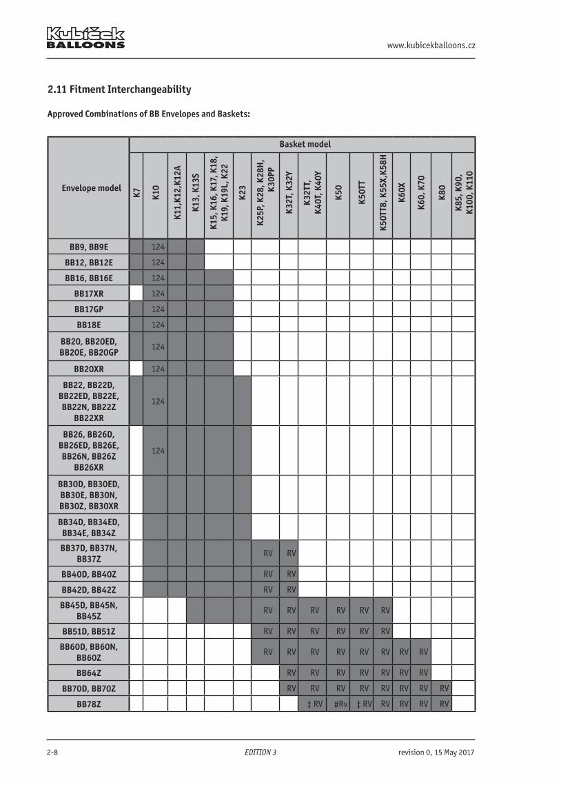
2.11 Fitment Interchangeability
Approved Combinations of BB Envelopes and Baskets:
Envelope model
Basket modelK7 K1
0
K11,
K12,
K12A
K13,
K13
S
K15,
K16
, K17
, K18
, K1
9, K
19L,
K22
K23
K25P
, K28
, K28
H,
K30P
P
K32T
, K32
Y
K32T
T,K4
0T, K
40Y
K50
K50T
T
K50T
T8, K
55X,
K58H
K60X
K60,
K70
K80
K85,
K90
,K1
00, K
110
BB9, BB9E 124
BB12, BB12E 124
BB16, BB16E 124
BB17XR 124
BB17GP 124
BB18E 124
BB20, BB20ED,BB20E, BB20GP
124
BB20XR 124
BB22, BB22D, BB22ED, BB22E, BB22N, BB22Z
BB22XR
124
BB26, BB26D, BB26ED, BB26E, BB26N, BB26Z
BB26XR
124
BB30D, BB30ED, BB30E, BB30N, BB30Z, BB30XR
BB34D, BB34ED,BB34E, BB34Z
BB37D, BB37N, BB37Z
RV RV
BB40D, BB40Z RV RV
BB42D, BB42Z RV RV
BB45D, BB45N, BB45Z
RV RV RV RV RV RV
BB51D, BB51Z RV RV RV RV RV RV
BB60D, BB60N, BB60Z
RV RV RV RV RV RV RV RV
BB64Z RV RV RV RV RV RV RV
BB70D, BB70Z RV RV RV RV RV RV RV RV
BB78Z ‡ RV #Rv ‡ RV RV RV RV RV
B.3102 Flight Manual
revision 0, 15 May 2017 >> EDITION 3 << 2-9
Envelope model
Basket model
K7 K10
K11,
K12,
K12A
K13,
K13
S
K15,
K16
, K17
, K18
, K1
9, K
19L,
K22
K23
K25P
, K28
, K28
H,
K30P
P
K32T
, K32
Y
K32T
T,K4
0T, K
40Y
K50
K50T
T
K50T
T8, K
55X,
K58H
K60X
K60,
K70
K80
K85,
K90
,K1
00, K
110
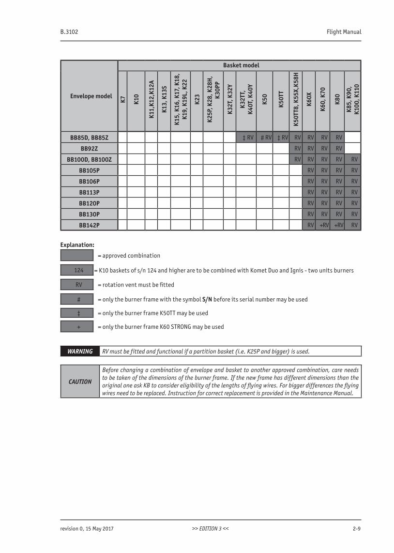
BB85D, BB85Z ‡ RV # RV ‡ RV RV RV RV RV
BB92Z RV RV RV RV
BB100D, BB100Z RV RV RV RV RV
BB105P RV RV RV RV
BB106P RV RV RV RV
BB113P RV RV RV RV
BB120P RV RV RV RV
BB130P RV RV RV RV
BB142P RV + RV + RV RV
Explanation:
= approved combination
124 = K10 baskets of s/n 124 and higher are to be combined with Komet Duo and Ignis - two units burners
RV = rotation vent must be fitted
# = only the burner frame with the symbol S/N before its serial number may be used
‡ = only the burner frame K50TT may be used
+ = only the burner frame K60 STRONG may be used
WARNING RV must be fitted and functional if a partition basket (i.e. K25P and bigger) is used.
CAUTION
Before changing a combination of envelope and basket to another approved combination, care needs to be taken of the dimensions of the burner frame. If the new frame has different dimensions than the original one ask KB to consider eligibility of the lengths of flying wires. For bigger differences the flying wires need to be replaced. Instruction for correct replacement is provided in the Maintenance Manual.
www.kubicekballoons.cz
2-10 EDITION 3 revision 0, 15 May 2017
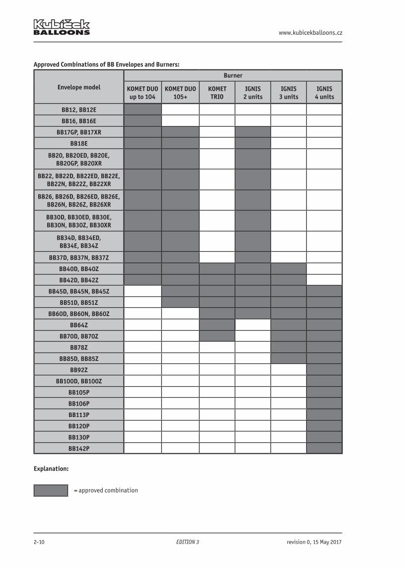
Approved Combinations of BB Envelopes and Burners:
Envelope model
Burner
KOMET DUO up to 104
KOMET DUO 105+
KOMETTRIO
IGNIS 2 units
IGNIS 3 units
IGNIS 4 units
BB12, BB12E
BB16, BB16E
BB17GP, BB17XR
BB18E
BB20, BB20ED, BB20E, BB20GP, BB20XR
BB22, BB22D, BB22ED, BB22E, BB22N, BB22Z, BB22XR
BB26, BB26D, BB26ED, BB26E, BB26N, BB26Z, BB26XR
BB30D, BB30ED, BB30E, BB30N, BB30Z, BB30XR
BB34D, BB34ED,BB34E, BB34Z
BB37D, BB37N, BB37Z
BB40D, BB40Z
BB42D, BB42Z
BB45D, BB45N, BB45Z
BB51D, BB51Z
BB60D, BB60N, BB60Z
BB64Z
BB70D, BB70Z
BB78Z
BB85D, BB85Z
BB92Z
BB100D, BB100Z
BB105P
BB106P
BB113P
BB120P
BB130P
BB142P
Explanation:
= approved combination
B.3102 Flight Manual
revision 2, 10 January 2018 >> EDITION 3 << 2-11
2.12 Other Manufacturers EquipmentBaskets and burners from certain other manufacturer may be combined with Kubicek envelopes. If so, the instructions given in the bulletin BB/22b-1 must be observed.Moreover, any bulletin or airworthiness directive issued and applicable for the parts used as a replacement for Kubicek part shall be considered mandatory for compliance of the balloon according to the same terms that the bulletin or airworthiness directive is required for compliance of the respective non-Kubicek parts
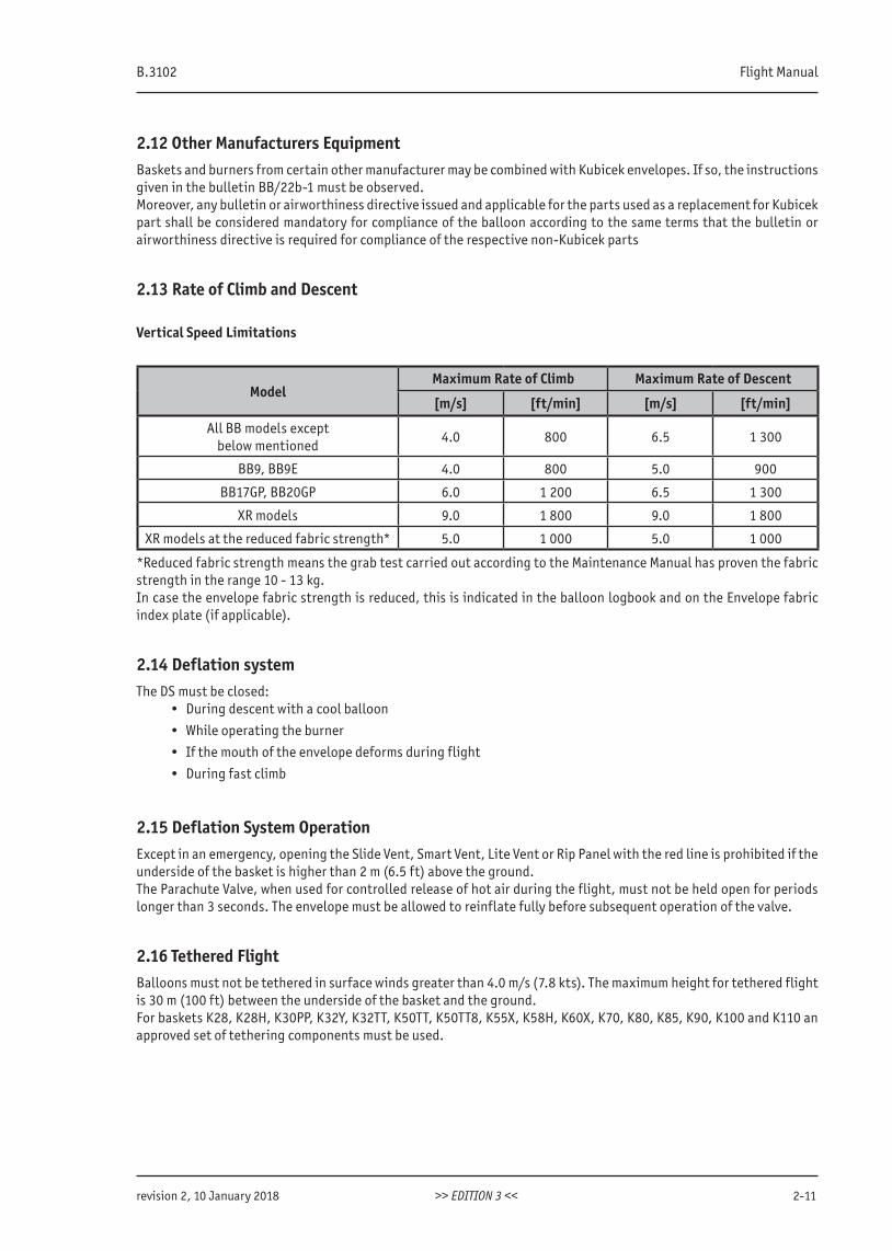
2.13 Rate of Climb and Descent
Vertical Speed Limitations
ModelMaximum Rate of Climb Maximum Rate of Descent
[m/s] [ft/min] [m/s] [ft/min]
All BB models exceptbelow mentioned
4.0 800 6.5 1 300
BB9, BB9E 4.0 800 5.0 900
BB17GP, BB20GP 6.0 1 200 6.5 1 300
XR models 9.0 1 800 9.0 1 800
XR models at the reduced fabric strength* 5.0 1 000 5.0 1 000
*Reduced fabric strength means the grab test carried out according to the Maintenance Manual has proven the fabric strength in the range 10 - 13 kg.In case the envelope fabric strength is reduced, this is indicated in the balloon logbook and on the Envelope fabric index plate (if applicable).
2.14 Deflation systemThe DS must be closed:
• During descent with a cool balloon
• While operating the burner
• If the mouth of the envelope deforms during flight
• During fast climb
2.15 Deflation System OperationExcept in an emergency, opening the Slide Vent, Smart Vent, Lite Vent or Rip Panel with the red line is prohibited if the underside of the basket is higher than 2 m (6.5 ft) above the ground.The Parachute Valve, when used for controlled release of hot air during the flight, must not be held open for periods longer than 3 seconds. The envelope must be allowed to reinflate fully before subsequent operation of the valve.
2.16 Tethered FlightBalloons must not be tethered in surface winds greater than 4.0 m/s (7.8 kts). The maximum height for tethered flight is 30 m (100 ft) between the underside of the basket and the ground. For baskets K28, K28H, K30PP, K32Y, K32TT, K50TT, K50TT8, K55X, K58H, K60X, K70, K80, K85, K90, K100 and K110 an approved set of tethering components must be used.
www.kubicekballoons.cz
2-12 EDITION 3 revision 0, 15 May 2017
Weight limitations for tethered flight:
Upper limit - the lowest of these values: Lower limit
75% of the MTOW or,
RMTOW (if established), or
Maximum balloon lifting capacity established according to chapter 5 of this Manual
MLW
WARNING The limitations stated above are based on the balloon structure. In every case the pilot must consider his skills, experience and actual condition when making decision about tethered flight.
NOTEIn some countries tethered flights of a hot-air balloon may be prohibited by the local aviationauthority. Balloons may not be used as a platform for bungee jumping.
2.17 Fuel CylindersAll fuel cylinders must be fitted with an outer water resistant protective layer. The limitations for material and thickness of the protective layer established by the cylinder manufacturer must be observed. Each fuel cylinder must be secured to the inside of the basket with at least 2 cylinder straps of an approved design.
WARNING No part of any fuel cylinder may overlap the upper edge of the basket.
WARNING Leather straps must not be used.
2.18 AltitudeMaximum permissible operating altitude is the altitude at which the burner fails to maintain ignition or the altitude at which the maximum allowable envelope temperature is reached, whichever happens first.For flights above 3 000 m (10 000 ft) of pressure altitude, flight crew and passenger oxygen must be used according to the applicable aviation requirements - details are given in chapter 2.26. National air space designations and limitati-ons must also be followed by the pilot.
2.19 Power Lines
WARNING Balloon must not be flown into contact with power lines! When crossing power lines, the balloon must be in level flight or ascending at a safe height above them.
2.20 Additional Limitations for Baskets with DoorThe basket fitted with the door or the passenger seat installed must only be flown under an envelope fitted with a Rotation Vent.
WARNING Door hinge pin(s) must be secured during the entire flight! The door must be closed during the entire flight!
2.21 Additional Limitations for Passenger SeatThe seat, trestle and attachment system must not be damaged. The passenger in the seat must be seated and wear the harness during the entire flight.
B.3102 Flight Manual
revision 0, 15 May 2017 >> EDITION 3 << 2-13
2.22 Additional Limitations for Removable Partitions• The partitions must be installed prior to balloon inflation and may not be moved or adjusted during inflation
or in-flight.• No more than 6 persons may be carried in one basket compartment or open space. For the K32TT basket the
maximum occupancy of the “compound” compartment made by removing the central partitions is 4 persons. For the K25P basket this number is 8, i.e. maximum occupancy is reduced to 6.
• Each passenger must have within reach at least one hand hold in his or her compartment.• Maximum two persons may stand behind each other during landing in “compound” compartment.• A minimum floor area for each person of 0.25m2 must be maintained regardless of arrangement of a partion.• The fuel cells may not be strapped to the non-wowen partitions of the pilot compartment.• The non-woven pilot compartment partitions are not considered as dividing the space. The maximum number of
persons in neighboring compartments need to be established as for an undivided compartment.• MTOW and MLW remain applicable.• Transversal pilot compartment, woven or non-woven, must always be used for flight.
WARNING No operation with the pilot compartment partition removed is allowed.
CAUTION Removing of partitions results in a lower maximum occupancy of the basket. Pay attention to observing the MLW and, mainly at “TT”, baskets to an even distribution of weigth.
2.23 Night Flying
Minimum Equipment
Additional compulsory equipment for night flights:• Night lighting equipment complying with applicable national requirements.
• Two independent, not hand-held, portable lights for illumination of instruments and equipment (e.g. headlamp) with a minimum lighting distance of 60 m.
2.24 Baskets with LugsThe maximum wind speed for take-off using the quick release attached to the basket lugs is 4.0 m/s (7.8 kts).
2.25 SmokingSmoking in the balloon and within 30 m (100 ft) is prohibited.
2.26 Oxygen supplyThe oxygen supply is required when
• all flight crew members engaged in performing duties essential to the safe operation of a balloon use supp-lemental oxygen for any period in excess of 30 minutes when the pressure altitude will be between 3 000m (10000 ft) and 4 000m (13 000 ft); and
• all occupants use supplemental oxygen for any period that the pressure altitude will be above 4 000m (13 000 ft).
• National regulations must also be observed.

www.kubicekballoons.cz
2-14 EDITION 3 revision 0, 15 May 2017
INTENTIONALLY LEFT BLANK
B.3102 Flight Manual
revision 0, 15 May 2017 >> EDITION 3 << 3-1
SECTION 3 - EMERGENCY PROCEDURES
3.1 IntroductionThis section specifies the actions of the pilot in case of emergency situations that may occur during flight. An emer-gency situation creates additional stress and requires a proper distribution of attention between flying the balloon and dealing with the emergency.
Every person piloting a Kubicek balloon must be thoroughly familiar with these emergency procedures. Be sure to have them studied, understood and reviewed regularly. Should an emergency arise, follow the instructions given in this section.
WARNING Emergency situations of all kinds shall be prevented by all possible means.
WARNING Failure to respond quickly and effectively to the emergencies documented in this section can result in injury or even death of passengers, others persons or the pilot.
WARNINGSAFETY OF THE PEOPLE IS THE PRIMARY CONCERN! Safety of the passengers and persons on the ground are the primary concern of the pilot in an emergency.Material damage is of secondary concern.
3.1.1 Passenger Emergency Positions for Landing or Collision
WARNING The correct positioning of persons in the basket is important for minimising the risk of injury!
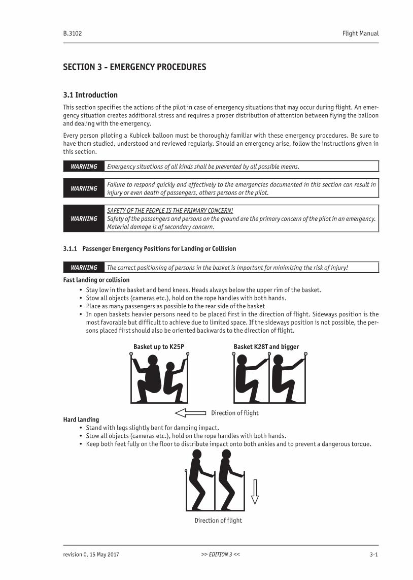
Fast landing or collision• Stay low in the basket and bend knees. Heads always below the upper rim of the basket.• Stow all objects (cameras etc.), hold on the rope handles with both hands.• Place as many passengers as possible to the rear side of the basket• In open baskets heavier persons need to be placed first in the direction of flight. Sideways position is the
most favorable but difficult to achieve due to limited space. If the sideways position is not possible, the per-sons placed first should also be oriented backwards to the direction of flight.
Hard landing• Stand with legs slightly bent for damping impact.• Stow all objects (cameras etc.), hold on the rope handles with both hands.• Keep both feet fully on the floor to distribute impact onto both ankles and to prevent a dangerous torque.
Basket up to K25P Basket K28T and bigger
Direction of flight
Direction of flight
www.kubicekballoons.cz
3-2 EDITION 3 revision 0, 15 May 2017
3.2 Collision with Obstacle
3.2.1 Decision: Landing or Climbing
With an obstacle in the flight path the pilot must decide soon enough about the solution: landing or climbing over the obstacle. Landing is advisable and safer. Climbing is preferred only when the pilot is sure the obstacle can be safely overflown.
3.2.2 Emergency Climb
1. Once the decision to climb over the obstacle is made, do not change the decision.
2. Heat as much as possible:
• On a single burner open the main blast valve from one fuel supply and the whisper burner from the second fuel supply.
• On a double, triple or quad burner each burner should use its own fuel supply. Do not use the cross-flow valve (if fitted).
NOTE Whisper burner will provide additional heat output.
3.2.3 Collision with a High Obstacle
When the obstacle is significantly higher than the balloon (chimney, tower, antenna...) and the collision is inevitable, proceed as follows:Priorities: Keep the balloon in level flight. Do not climb or descend.
1. Maintain horizontal flight.
2. Passengers are briefed to adopt correct emergency position for collision.
3. Prevent persons from falling out of the basket during impact.
4. Decide about further steps:
a. If possible and safe to do so, fly away and land behind the obstacle.
b. Otherwise stabilize the basket, inform your crew. If necessary inform ATC and call for help. Nobody leaves the basket.
3.2.4 Collision with a Low Obstacle - Basket Remains on the Ground
When the obstacle is of approximate balloon height or lower (tree, house, car, fence...), proceed as follows: Priorities: Get the basket as low as possible, preferrably on the ground.
1. Vent to descend and lay the envelope before the obstacle.
2. Passengers are briefed to adopt correct emergency position for collision.
3. Shut all cylinder valves.
4. Prevent the balloon from lifting off again by opening the deflation system by the red line.
5. Prevent passengers from leaving the basket until so instructed.
6. Inform your crew and the ATC if necessary.
B.3102 Flight Manual
revision 0, 15 May 2017 >> EDITION 3 << 3-3
3.3 Collision with Electric Power LinesPriorities: Hitting power lines with the basket wires is the most dangerous situation. Get the basket below the power lines at all costs.
Prior to the contact:
1. Vent to descend
2. Passengers are briefed to adopt correct emergency position for collision with faces down, protecting sight and not touching the fuel cylinders and other metal parts.
3. Shut all cylinder valves and vent fuel hoses.
After the contact:4. Prevent the balloon from lifting off again.
5. Call emergency line (112, 911 or local equivalent) for help and information about disconnection of the power line.
6. Inform your crew and the ATC.
7. Have the passengers exit the basket as the situation allows. Do not touch the basket and ground at the same time.
8. Do not attempt to recover the balloon from the wires without an assistance of emergency units.
3.4 Midair Collision with Another BalloonPriorities:
• Make the other balloon’s pilot aware of the the risk of contact.• Avoid direct contact of the basket with envelope.• If basket-envelope collision is inevitable try to minimize the relative vertical speed.
Lower balloon:1. Stop climbing or accelerate descent.
2. In case of contact heat to keep the envelope inflated. Check the damage.
3. During fall or descent together with the upper balloon jettison fuel cylinders except one (ones) to be used for slowing down the descent in case the upper balloon detaches.
4. Instruct passengers to adopt correct position for a hard landing.
5. Prepare for hard landing (see chap. 3.6.3)
Upper balloon:1. Stop descending or accelerate climb.
2. Prevent the lower envelope from direct contact with your basket with your hands or legs. When the other enve-lope is too close to your burner, avoid heating to prevent damage to other envelope.
3. In case the lower envelope is torn, try to attach it to your basket.
4. Maintain both balloons in acceptable rate of descent by intense heating.
5. Land without regard to obstacles on the ground.
3.5 Damage to the Envelope in FlightPriorities: Keep flying the balloon to avoid a hard landing.
1. Heat to keep the envelope inflated. If the envelope mouth closes blow fire through the fabric in a convenient place. Check the damage.
2. Keep in a low altitude and land as soon as possible.
3. If the balloon descends uncontrollably, jettison gradually all heavy objects including fuel cylinders and prepare passengers for a hard landing. The cylinder used for heating is to be jettisoned last.
4. Prepare for hard landing (see 3.6.3).
www.kubicekballoons.cz
3-4 EDITION 3 revision 2, 10 January 2018
3.6 Non-standard Landing
3.6.1 Fast Landing
Landing in a relatively high surface windPriorities: Primarily avoid persons from falling out of the basket or their injury from loose objects. Make a tangential contact to the ground with little vertical speed.
1. Select a suitable landing field, maintain desired landing trajectory.
2. If a RV is fitted, rotate the balloon, so the balloon lands on the longer side of the basket.
3. Passengers to adopt correct emergency position for fast landing. Prepare them for being dragged on the ground after landing.
4. Descend gently.
5. Consider possibility to stop the envelope with a convenient obstacle (tree, bushes...)
6. Switch off the pilot flames on all burner units.
7. Red line - open the deflation system completely.
8. Prevent people from leaving basket until so instructed.
WARNING Combination of fast horizontal motion and vertical descend is extremely dangerous and must beavoided. The touchdown is to be performed with as low a rate of descend as possible.
3.6.2 Deflation System Malfunction
Should this emergency arise, the same priroties and procedures apply as the fast landing (see 3.6.1). If the envelope is fitted with a rotation vent, use it for venting. Pull on both lines to vent air. Be prepared for a prolonged drag of the basket after landing.Report the trouble to your ground crew so they can be of help as soon possible.
3.6.3 Hard Landing
Landing with a high rate of descentPriorities: Everyone in the basket must adopt correct emergency position to prevent injuries to legs and ankles.
1. If a RV is fitted, rotate the balloon so it lands on the longer side of the basket.
2. Passengers to adopt correct emergency position for hard landing.
3. Report a hard landing to your ground crew.
4. Shut all cylinder valves and vent fuel hoses.
5. Open the deflation system completely when close to the ground.
6. Prevent people from leaving the basket until so instructed.
3.6.4 Landing in Fog
1. Keep a very slow descend of not more than 0.5 m/s (10 ft/min) with the use of variometer.
2. Carefully check the space below the basket and avoid obstacles.
3.6.5 Landing into Dry Vegetation (Grain, Grass)
1. Shut all pilot flames and cool burners before touchdown.
2. Shut the main valves on the fuel tanks before deflating the balloon.
B.3102 Flight Manual
revision 0, 15 May 2017 >> EDITION 3 << 3-5
3.6.6 Landing in Thermal or Gusty Conditions
Priorities: Try to land into the center of a lagre open area.
1. Keep level flight at the altitude where the wind direction remains stable and find a suitable landing area.
2. Make a rapid descent aiming into the center of the landing area.
3. Open the deflation system completely when close to the ground.
3.6.7 Landing into Tall Vegetation (Forest)
Priorities: Carefully choose landing area - preferably glade or path. If not possible, land gently among trees.
1. Inform your crew or the ATC.
2. Select the most suitable landing area.
3. Keep all control lines and crown line short.
4. Passengers to adopt correct emergency position for fast landing.
5. Prevent passengers from falling out of the basket during possible impact.
6. Control a gentle descent among trees.
7. Empty the fuel hoses and switch off the pilot lights before the balloon reaches the vegetation.
8. If the basket remains hung on a branch, stabilize your position, inform your crew, ATC and call for help. Nobody leaves the basket.
9. If the basket reaches ground, let the envelope fall freely and do not pull it aside with the crown line.
3.6.8 Landing into Build-up Area
1. Keep low and try to choose a suitable area for landing.
2. Prepare the drop line in advance for an imminent use.
3. Inform your crew.
4. Release the drop line when appropriate and ask your crew or other people on the ground to drag the balloon away from dangerous objects (power lines, pylons, chimneys...)
5. Land carefully at a suitable place.
6. In a limited area let the envelope fall freely and do not pull it aside with the crown line.
3.6.9 Landing into Water
When unable to overfly the water due to low fuel or when unintentionally reaching open sea.Priorities: Secure for non-swimmers.
1. Identify non-swimmers among passengers.
2. Report your position to ATC and your crew. Ask for help.
3. Fly low, burn the maximum fuel, and avoid soaking the emergency means of ignition.
4. Land slowly on water once the fuel cylinders are empty.
5. After the envelope has fallen on the water, release it from the basket.
6. Use the basket with fuel cylinders as raft and wait for rescue.
www.kubicekballoons.cz
3-6 EDITION 3 revision 2, 10 January 2018
3.7 Burner Failures
3.7.1 Pilot Light Failure
1. Heat with another burner unit to initiate climb.
2. Ignite the failed pilot flame by firing another unit’s main burner.
3. Check fuel quantity, hose connections, and vapor fuel pressure regulator (if used).
If no pilot light works:4. Check vapor fuel hose and pressure regulator (double hose burners), check the fuel hose (single hose burners).
5. Try to ignite pilot flame with piezo or another source of ignition.
If failure remains:6. Ignite main burner with an emergency ignition source.
7. Keep a small flame from the main burner or use the whisper burner as a pilot light.
8. Land as soon as practicable.
3.7.2 Main Burner Valve Blocked Open
1. Try to move the main burner lever, if still blocked then:
2. Shut off the liquid fuel valve on the respective cylinder.
3. Use another burner unit for heating or use the cylinder valve to control the burner.
4. Land as soon as practicable.
3.7.3 Main Burner Failes to Burn
1. Heat with another burner unit or whisper burner to initiate climb.
2. Check fuel quantity, hose connections and cylinder valve.
3. Land as soon as possible with the use of another burner unit.
3.7.4 No Burner Unit Working
1. Check fuel quantity, cylinder valves and hose connections for all burner units connected. If failure remains, then:
2. Reconnect to another fuel cylinder. Check REGO connector on a disconnected hose is free of a seal of another cylinder. If failure remains, then:
3. Prepare for a hard landing (see chap. 3.6.3) and instruct passengers to adopt proper positions.
B.3102 Flight Manual
revision 2, 10 January 2018 >> EDITION 3 << 3-7
3.8 Fire
CAUTION
The fire extinguisher must always be used in the vertical position. Be aware that it will only last for a few seconds.If a dry powder extinguishing is used to fight the fire then all traces of the powder must be removed as soon as possible after landing because the powder, when exposed to the air, is extremely corrosive.
3.8.1 Fire in the Air
1. Shut off liquid fuel valves on all cylinders. In case the fire occurs on the cylinder in use , close the shut off valve with the use of the fire blanket.
2. Open main burner valves to vent fuel with the use of fire resistant cloth.
3. Use fire extinguisher to extinguish the fire.
4. Land as soon as possible using the undamaged burner unit/fuel system.
3.8.2 Fire on the Ground
1. Shut off liquid fuel valves on all cylinders. In case the fire occurs on the cylinder in use, close shut off valve with the use of fire blanket.
2. Open main burner valves to vent fuel with the use of fire resistant cloth.
3. Use fire extinguisher to extinguish the fire.
4. Open the DS with red line.
WARNING If it is not possible to extinguish the fire immediately then evacuate everyone to a safe distance as soon as possible because the cylinders may explode.
3.9 Gas Leak
1. Shut off all the pilot lights.
2. Shut off fuel to the respective fuel hose.
3. Open the main burner valve to empty the fuel hose.
4. When propane is no longer detectable relight the not affected burner unit(s).
5. Land as soon as possible.
3.10 Accidental Operation of SLV, SV or LV in Flight
1. If the red line was pulled untintentionally in flight, close the DS immediately by RED-WHITE line (SLV or SV) or white line (LV).
WARNING The Vent panel will not automatically re-close on release of the red line.
3.11 Night Flying
Entanglement of Light
If the light is entangled firmly in a tree or another obstacle on the ground try to free it by heating the balloon or cutthe light cable with a knife.
www.kubicekballoons.cz
3-8 EDITION 3 revision 0, 15 May 2017
Position Light Malfunction
If the red flashing light is not working, take the following steps:
1. Check the electrical connections. If failure remains then:
2. Change the fuse in the male connector. Unscrew the connector top, remove the fuse and replace it with a new one. Spare fuses are in the position light storage bag. If failure remains, then:
3. Use irregular short bursts of whisper burner to illuminate the envelope. When in controlled airspace inform the ATC about the failure.
B.3102 Flight Manual
revision 0, 15 May 2017 >> EDITION 3 << 4-1
SECTION 4 - NORMAL PROCEDURES
4.1 Introduction
Use of Written Checklists
This section provides information for checklists and procedures for normal operation. Handy checklists on flip cards are a practical solution for balloon pilots. Pilots should always use written checklists. Balloon pilots need checklists because they are frequently distracted by passengers, by-standers and other balloon traffic at events. Balloon pilots are encouraged to create their own checklists. These checklists can be customized to the needs of the pilot and the configuration of the balloon model. As a minimum, written checklists should be used for the following procedures and maneuver: Layout and Assembly, Launch, Ascent, Level Flight, Descent, Landing and Recovery. Other checklists can be created for: Preflight Inspection, Inflation, Pre-Launch, Launch over Obstacle, High Wind Landing and emergency procedures.
4.2 Flight PlanningThe following pre-flight preparation is to be completed before leaving for the launch field:
4.2.1 Meteorology
Obtain a current aviation weather briefing for the expected flight time and location. Make sure the meteorological conditions are expected to remain within limits for the duration of the flight. High winds, thermals, gusts, fronts and thunderstorms are conditions not favorable for flight. Pay attention to local meteorological conditions. Ask local pi-lots if you are not familiar with local flying areas and special weather conditions for balloons. Sunrise is the only time to fly is some areas.Obtain a forecast of the winds aloft to plan the launch location and desired flight path. Release a small helium balloon to determine the latest wind situation.Consider the effect of ambient temperature on the fuel pressure and performance of the balloon.Obtain an updated weather forecast. The final weather evaluation is to be made just prior to the launch to ensure that existing conditions are still suitable for the flight.Make sure that the visibility stays above 1 NM (or minimum limit required by the local authorities) during the entire flight.
4.2.2 Airspace
Use an official up-to-date aviation chart to verify the airspace limitations, minimum visibility and required equipment (radio, transponder, night light).
4.2.3 Paperwork
Verify all necessary documents required by the appropriate national authorities are present and valid.
4.2.4 Site Planning
With knowledge of the weather situation and amount of fuel select a launch site with regards to its size and lan-downer’s permission, expected flight trajectory and obstacles. Consider suitable landing area with several backup landing sites.
WARNING Ensure that there are no power lines in the area selected for take-off.
www.kubicekballoons.cz
4-2 EDITION 3 revision 0, 15 May 2017
4.2.5 Balloon Weight Limits
Verify the balloon will remain within its weight limitations - MTOW, Maximum lifting capacity, MLW - during the entire flight. Consult chapter 5 of this Manual for detailed instructions.
4.2.6 Check of Completness and Fuel
During or after loading of equipment verify completeness of equipment. Verify the amount of fuel, its pressure and any need for pressurization of fuel cylinders.
NOTEFuel consumption will vary greatly with different flight profiles and ambient temperature. A fuelreserve for 30 minutes of flight is recommended.When uncertain about the fuel consumption of a balloon, ask the manufacturer for advice.
CAUTIONPay particular attention when intending to fly an envelope of bigger size with only a minimum allowed fuel on board. This will allow for only a short flight.
CAUTION
The fuel consumption is significantly increased by:
• envelope temperature above 115°C (239°F)• abrupt maneuvring• frequent in-flight venting• use of RV
4.2.7 Flight Planning and Weather for Night Flying
Make a careful flight plan including weather, fuel consumption and maximum operation time of the position lights. Ensure adequate quantity of fuel is carried to permit a reserve for at least 30 minutes of flight after sunrise.
Before departure to the takeoff site: Make sure the battery is fully charged. Check that the position lights work correctly.
CAUTION At night the fuel consumption is substantially higher due to the absence of solar heating.
WARNING Landing at night is dangerous and needs to be avoided.
4.3 Preparation, Assembling the Balloon and TAKE-OFF
4.3.1 Launch Site
Select a flat area large enough to lay the balloon out safely with easy access for the retrieve vehicle without obstruc-tion in the downwind direction and without objects that could damage the envelope. The area for spreading the enve-lope should ideally be a smooth grass surface without rocks, sticks, tough shrubs and other objects likely to damage the envelope.Manipulating the balloon envelope on abrasive surfaces (concrete, tarmac, paving, sand...) should also be minimized as it causes excessive degradation of envelope fabric. Is is recommended that the envelope be unpacked into a long “noodle” and let it be blown to the sides by the inflation fan which helps to minimize dragging the fabric on the abra-sive surface.Pay attention to the landowner’s rights and obtain permission to use the land if necessary.The selected site must allow for a safe departure clear of obstacles with the actual load and particularly wind direction and speed. The stronger the wind the farther the balloon must be placed from obstacles.
WARNING Make sure there are no power lines in the departure path.
B.3102 Flight Manual
revision 0, 15 May 2017 >> EDITION 3 << 4-3
NOTEIf the wind speed is strong (more than 4 m/s [8 kts]), it is recommended that you use a launch site that gives protection from the wind.
4.3.2 Decision on the Flight
Weather Weather conditions within limits, no thermals, no thunderstorm or any other weather phenomena possibly dangerous in the vicinity of the intended flightLaunch site No downwind obstaclesWeight The balloon is within weight limits and capable of staying that way during the entire flightFuel At least the minimum quantity of fuel is present and is enough to complete the intended flight
WARNING
NO FLIGHT IS PERMITTED if there is a chance that the surface wind speed during the flight will exceed limitations for safe landing (see 2.2). Never attempt to fly when there is thunderstorm activity in the area, ahead of approaching frontal systems, or near severe weather of any kind (turbulence, thermals, or wave currents etc).
4.3.3 Crew Briefing
The briefing for the ground crew is done by the pilot preferably before unpacking the balloon and no later thanbefore starting the inflation fan. A map should be provided the crew with the launch site identified and the courselaid out showing direction and length of flight.
WARNINGInstruct every crew member, especially the crown crew, to immediately release all ropes or other equip-ment if there is a risk of being lifted off the ground!
Crown Crew Briefing Clothes: Strong gloves, suitable shoes Dos: Hold the end of the crown rope, stabilize the envelope by pulling it during inflation. Prevent it from
rolling from side to side and rising before it is buoyant. During hot inflation pull the rope back, slow down the upright motion of the envelope and move
slowly towards the basket. As the envelope comes upright, pull hard to prevent it from swinging over the basket. Upon pilot’s signal bring the crown rope and clip it to the basket. Then help to hold the basket. Inform pilot if anything unusual was observed during the inflation. Don’ts: Don’t wrap the rope aroud the waist, arm or any object. Don’t accept help from other people.
NOTESmaller envelopes (below 10 000 m3 / 353 100 cu.ft.) are fitted with one crown line. Bigger envelopes have two crown lines.
WARNINGThe crown crew person should never wrap the crown line around any part of the body. Nor should the loop in the end be looped around the wrist.
Mouth Crew Briefing Equipment: Strong gloves, clothes made of natural fibre or heat resistant fabric protecting arms and legs from
burner heat. Dos: Hold the envelope mouth open with the flying cables taut and clear of the burner flame. Hold the basket once the envelope is upright One person to control the inflation fan, direct the airflow into the mouth of the envelope parallel to
the burner flame, turn off the fan on pilot’s signal and move it clear of the balloon. One person to keep bystanders away from the balloon and quick release rope if necessary. Don’ts: Don’t put legs between flying cables. Don’t allow bystanders to help or walk over or under the quick release rope.
www.kubicekballoons.cz
4-4 EDITION 3 revision 0, 15 May 2017
WARNINGMouth crew should be briefed to never allow a foot or leg to get inside a mouth cable as this can result in injury.
WARNINGQuick release rope can fling sharply when released. Keep bystanders away from the aera between the basket and tether point at all times to prevent injury.
WARNINGThe crew operating the fan should not wear any loose clothing, scarf, neck lanyard, long loose or braided hair as these items can pass through the fan guard.
WARNING Always inspect the fan before use to insure safe function and all fasteners and cage are secure.
4.3.4 Passengers briefing
A correct briefing to the passengers is essential for the safety of the flight. Passengers receive this briefing fromthe pilot before the basket is layed down. Correct landing and emergency positions are to be physically demonstrated. Dos: Follow the pilot’s instruction at all times. Stay clear of the inflation fan. Before landing: Stow all loose object such as cameras. On landing: Adopt landing position. Hold on to rope handles to maintain this position. Stand with legs together and with their knees slightly bent and head level with the basket
top padding Keep feet flat on the basket floor. Keep hands and arms within the basket. Watch the progress of the landing and brace for the touch-down. Be aware that the basket on landing may tip over and drag along the ground. Remain in the basket until instructed to leave by the pilot. Don’ts: Hold onto the fuel hoses or interfere with the control lines, burner controls or fuel cylinder valves. Interfere with any of the balloon controls. Smoke in the balloon or within 30 m (100 ft) of the basket. Throw anything from the basket. Touch the door and partitions or securing carabiners. On landing: Wrap their arms around the burner support rods. Leave the basket before instructed to do so by the pilot.
WARNING
It is dangerous to rely on a passenger to assist with the deflation line, fuel system, or as navigator or obstacle spotter during the flight or during the landing. These are pilot responsibilities which should not be delegated to persons without balloon piloting experience and without authority to act on their own judgment.
WARNING Do not allow any part of the body, including hands, to wrap around the upright poles on landings.
WARNINGThere is a risk of personal injury if an unexperienced person (e.g. passenger) is asked to help with the balloon handling before TakeOFF or after landing. If you do so always provide to such person detailed instruction which includes means of minimizing of the associated risks.
4.3.5 Unpacking and Assembly of the Balloon
1. Unload the entire balloon, inflation fan and quick release from the vehicle or trailer. Orient the basket with the red--marked wire to the right forward position. Place the vehicle on the upwind of the basket, 3 - 5 m (10 - 15 ft) away and brake it well. Place the envelope in its bag on the downwind side of the basket far enough apart so that the
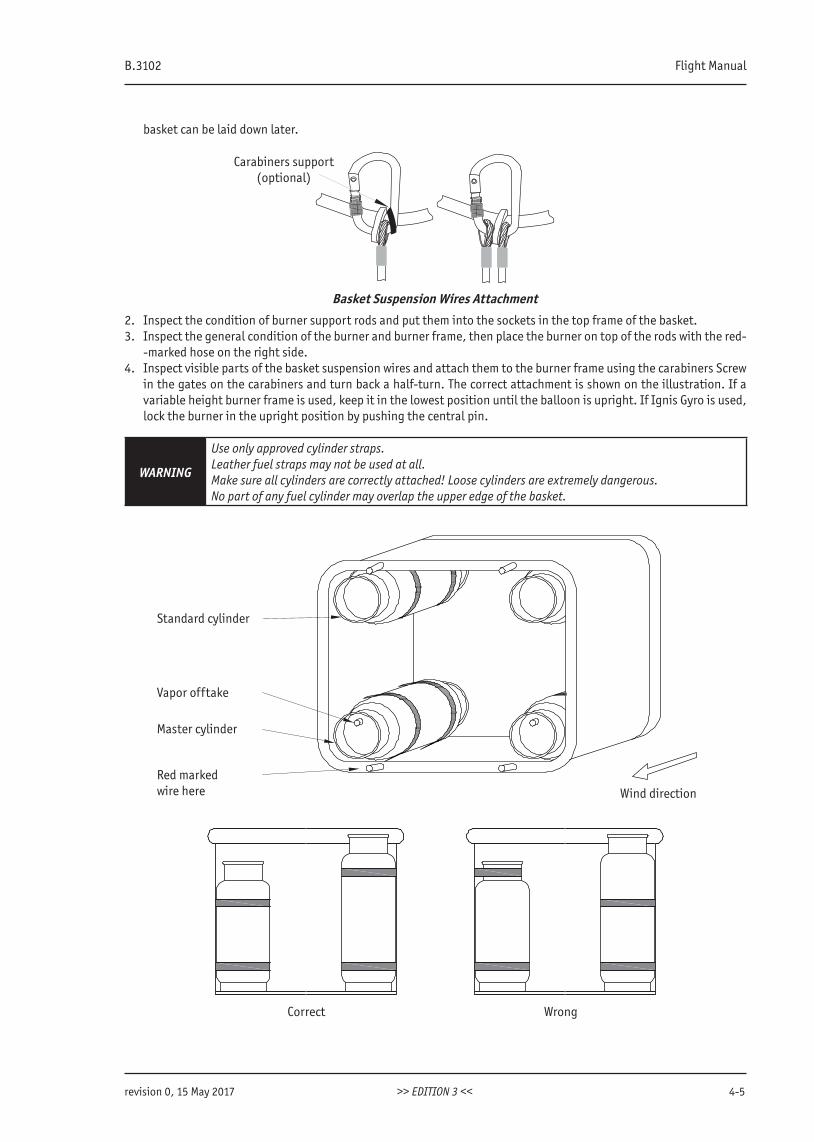
B.3102 Flight Manual
revision 0, 15 May 2017 >> EDITION 3 << 4-5
basket can be laid down later.
Basket Suspension Wires Attachment
Carabiners support (optional)
2. Inspect the condition of burner support rods and put them into the sockets in the top frame of the basket.3. Inspect the general condition of the burner and burner frame, then place the burner on top of the rods with the red-
-marked hose on the right side. 4. Inspect visible parts of the basket suspension wires and attach them to the burner frame using the carabiners Screw
in the gates on the carabiners and turn back a half-turn. The correct attachment is shown on the illustration. If a variable height burner frame is used, keep it in the lowest position until the balloon is upright. If Ignis Gyro is used, lock the burner in the upright position by pushing the central pin.
WARNING
Use only approved cylinder straps.Leather fuel straps may not be used at all.Make sure all cylinders are correctly attached! Loose cylinders are extremely dangerous.No part of any fuel cylinder may overlap the upper edge of the basket.
Standard cylinder
Vapor offtake
Master cylinder
Red marked wire here Wind direction
Correct Wrong
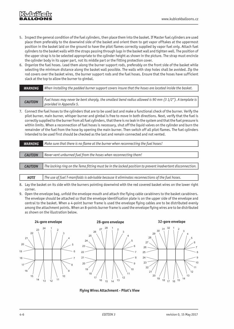
www.kubicekballoons.cz
4-6 EDITION 3 revision 0, 15 May 2017
5. Inspect the general condition of the fuel cylinders, then place them into the basket. If Master fuel cylinders are used place them preferably to the downwind side of the basket and orient them to get vapor offtakes at the uppermost position in the basket laid on the ground to have the pilot flames correctly supplied by vapor fuel only. Attach fuel cylinders to the basket walls with the straps passing through lugs in the basket wall and tighten well. The position of the upper strap is to be selected appropriate to the cylinder height as shown in the picture. The strap must encircle the cylinder body in its upper part, not its middle part or the fitting protection cover.
6. Organize the fuel hoses. Lead them along the burner support rods, preferably on the front side of the basket while selecting the minimum distance along the basket wall possible. The walls with step holes shall be avoided. Zip the rod covers over the basket wires, the burner support rods and the fuel hoses. Ensure that the hoses have sufficient slack at the top to allow the burner to gimbal.
WARNING When installing the padded burner support covers insure that the hoses are located inside the basket.
CAUTIONFuel hoses may never be bent sharply, the smallest bend radius allowed is 90 mm (3 1/2“). A template is provided in Appendix 5.
7. Connect the fuel hoses to the cylinders that are to be used last and make a functional check of the burner. Verify the pilot burner, main burner, whisper burner and gimbal is free to move in both directions. Next, verify that the fuel is correctly supplied to the burner from all fuel cylinders, that there is no leak in the system and that the fuel pressure is within limits. When a reconnection of fuel hoses is necessary, shut off the liquid valves on the cylinder and burn the remainder of the fuel from the hose by opening the main burner. Then switch off all pilot flames. The fuel cylinders intended to be used first should be checked as the last and remain connected and not vented.
WARNING Make sure that there is no flame at the burner when reconnecting the fuel hoses!
CAUTION Never vent unburned fuel from the hoses when reconnecting them!
CAUTION The locking ring on the Tema fitting must be in the locked position to prevent inadvertent disconnection.
NOTE The use of fuel T-manifolds is advisable because it eliminates reconnections of the fuel hoses.
8. Lay the basket on its side with the burners pointing downwind with the red covered basket wires on the lower right corner.
9. Open the envelope bag, unfold the envelope mouth and attach the flying cable carabiners to the basket carabiners. The envelope should be attached so that the envelope identification plate is on the upper side of the envelope and central to the basket. When a 4-point burner frame is used the envelope flying cables are to be distributed evenly among the attachment points. When an 8-points burner frame is used the envelope flying wires are to be distributed as shown on the illustration below.
Flying Wires Attachment - Pilot’s View
24-gore envelope 28-gore envelope 32-gore envelope
B.3102 Flight Manual
revision 2, 10 January 2018 >> EDITION 3 << 4-7
NOTE The arrangement of flying wires can differ in the case the botton end from anothermanufacturer is use. If in doubt, contact KB for advice.
10. The carabiner on the red flying cables attaches to the carabiner on the red basket wires. Check that the flying cables are not twisted and then close the screw gates on the carabiners fully and release by a half-turn.
11. Pull the envelope from its bag and spread it out either directly onto the ground or onto a pre-positioned ground she-et. Fully deploy the crown line downwind. If two crown lines are used, deploy them into a wide V-shape. On a smooth surface spread the envelope by pulling on load tapes only. On a hard surface use the fan to spread the envelope. Attach the scoop to the envelope carabiners. Place DS and RV control lines into the basket. The redwhite line (vent line) of the SV and SLV and red-white (vent line) and white line (reset line) of the LV are to be preferably placed in their bags in the basket. When using the electronic thermometer attach its sensor correctly onto the envelope. In the envelope, pay attention not to confuse the temperature sensor wire and the antenna.
12. Attach a quick release to the upwind envelope carabiners and the secure the other end of the restraint rope to a secure anchor point (details in chap. 4.3.6).
13. Position the fan on the side of the basket. Make sure that someone looks after the fan whenever it is turned on.
WARNINGFailure to screw down the locking collar of a carabiner may result in distortion of the carabiner, making connection and disconnection of the carabiner difficult or impossible in the future. This could cause po-ssible failure under extreme flight loading, which could result in injury or death.
Additional information for assembling the balloon:
Always lay the basket with the door closed and on the up side.The pilot must also decide on arrangement of removable partitions, basket occupancy and distribution of passengers. All items must be properly installed and secured before the basket is laid down for inflation.When the pilot chooses to use the seat, it should be installed into the basket prior to cold inflation.
Seat installation:1. Insert the pins in the underside of the trestle into the grooves in metal plates on the basket floor and slide the
seat sideways to fasten all pins.2. Screw in the central bolt and tighten by hand.
NOTEThe correct orientation of seats must be taken into account. All seats must be installed so that allseating passengers face the same direction with their backs to the direction of flight before landing, ifpossible.
During pre-flight preparation:
The weight and floor area occupancy of the seat is to be taken into account. The actual weight of the complete set is engraved on the trestle.Floor area occupied by the seat: 0.27 m2 (2.9 sq. ft)
4.3.6 Quick Release
WARNINGThe quick release is an essential safety item that shall be used for all inflations, even during calm con-ditions.
Standard Quick Release
Attach the carabiners at both ends of webbing to the envelope carabiners. Make a loop on the restrain line and place it into the jaw of the quick release and lock it with a securing pin. The other end of the restrain line is to be fixed to a solid ground point or to the front of a heavy vehicle.
Y-type Quick Release
Place the quick release on the attachment lug closest to the pilot’s compartment. Fix one end of the rope to another lug with a carabiner, next pass the rope through the ring at the end of the restrain line, then place the rope loop into the jaw of the quick release and lock it with a securing pin. The other end of the restrain line is to be fixed to a solid
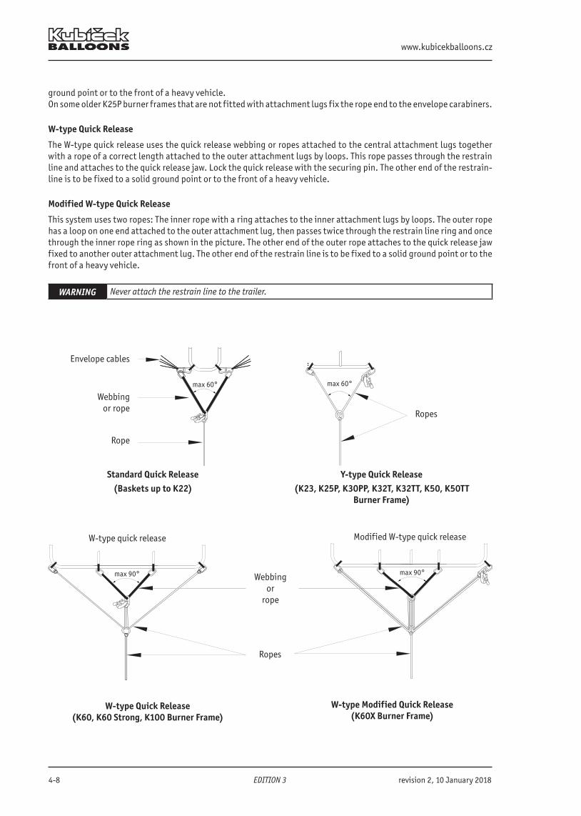
www.kubicekballoons.cz
4-8 EDITION 3 revision 2, 10 January 2018
ground point or to the front of a heavy vehicle.On some older K25P burner frames that are not fitted with attachment lugs fix the rope end to the envelope carabiners.
W-type Quick Release
The W-type quick release uses the quick release webbing or ropes attached to the central attachment lugs together with a rope of a correct length attached to the outer attachment lugs by loops. This rope passes through the restrain line and attaches to the quick release jaw. Lock the quick release with the securing pin. The other end of the restrain-line is to be fixed to a solid ground point or to the front of a heavy vehicle.
Modified W-type Quick Release
This system uses two ropes: The inner rope with a ring attaches to the inner attachment lugs by loops. The outer rope has a loop on one end attached to the outer attachment lug, then passes twice through the restrain line ring and once through the inner rope ring as shown in the picture. The other end of the outer rope attaches to the quick release jaw fixed to another outer attachment lug. The other end of the restrain line is to be fixed to a solid ground point or to the front of a heavy vehicle.
WARNING Never attach the restrain line to the trailer.
Standard Quick Release(Baskets up to K22)
Y-type Quick Release(K23, K25P, K30PP, K32T, K32TT, K50, K50TT
Burner Frame)
W-type Quick Release (K60, K60 Strong, K100 Burner Frame)
Webbingor rope
Rope
max 60°
W-type quick release
Ropes
max 60°
max 90°
W-type Modified Quick Release (K60X Burner Frame)
Ropes
Modified W-type quick release
max 90°
Envelope cables
Webbingor
rope
B.3102 Flight Manual
revision 2, 10 January 2018 >> EDITION 3 << 4-9
WARNINGNo person is allowed in the area between the basket and the front of a vehicle due to high risk of serious injury.
WARNING
The most common angle between webbing arms is between 60 and 90 degrees, as per quick release type, for preventing overstressing of the burner frame. For 60 degrees the lengths of the webbing arms are to be the same as the distance between their atta-chment points - envelope carabiners or attachment lugs.For verifying the 90 degrees the pilot can use any suitable rectangular object e.g. map folder, flight log etc.
WARNING
The fixed point for attaching the quick release rope must be able to carry the following load:MTOW of the respective balloon + 800 kg (1760 lb) This load is established for the maximum surface wind speed allowed for take-off. In slower wind the load capacity of the fixed point can be reduced in direct proportion to the maximum allowed and actual surface windspeed.
WARNING The quick release shall be operated by the pilot only.
Basket tethering lugs
For takeoff the quick release can be attached to the basket lugs instead of envelope carabiner or burner frame lugs. The quick release type remains the same as it would be without basket lugs; according to the burner frame.
4.3.8 Cold Inflation and Pre-flight Check
CAUTIONIn windspeeds 5.0 m/s (10 kts) and higher the controllability of the balloon is difficult. It is reco-mmended to use two inflation fans and sufficient number of crew members for envelopes of 7000 m3 and bigger.
1. With the crew in position start the inflation fan which is placed in the braked position on the left side of the bas-ket. The air flow should be aimed to the left of the mouth center so that the burner flame is not disrupted. The fan remains turned on during the entire inflation. The crew turns it off on the pilot’s instruction.
2. One or two crew members remain at the crown and close the DS by connecting the proper velcro tabs identified by numbers and color. Start at the top (first and last number) and continue gradually downwards.
3. The pilot makes an inspection of the basket and both the internal and external parts of the envelope:
www.kubicekballoons.cz
4-10 EDITION 3 revision 2, 10 January 2018
Envelope Fabric damage within permitted limitsCrown ring Crown ring, load tapes and load tapes loops undamaged and the crown line pr-
operly attached and undamagedEnvelope mouth Load tapes and load tapes loops are undamaged, and the fabric damage within permitted limitsSteel flying wires No broken strands, rust, kinks, heat damage, entanglementKevlar flying wires Check all the wires along their whole length. The wire must be flexible and free
of mechanical damage. The yellow core must not be exposed. Damaged wires must be replaced. Instructions are given in Appendix 3 of this Manual.
Joints of load tapesand flying wires All load tape loops, carabiners and protecting sleeves are free of damageDS and RV lines Check them along their entire length for damage and free of knots and twists.Paralite bungee (if fitted) UndamagedPulleys Undamaged and rotating freelyTemperature streamer Present and the flag not twistedTempilabel No signs of overheatingDS panel Correctly placedDeflation openings (if fitted) All closedQuick release andrestrain line Quick release correctly attached to the envelope carabiners or burner frame
lugs if fitted. Restraint line attached to an anchor pointCarabiners All present, undamaged, correctly arranged and secured
WARNINGHeat damage, which may cause a significant loss of strength of a steel wire, is indicated bycharring, blackening or bluing, or by a presence of a permanent deformation or kink after being bent.
CAUTION Keep loose items away from the inflation fan to prevent entanglement with the propeller.
CAUTIONThe temperature sensor must be placed in the same distance from the envelope skin as the melting stre-amer.
Basket Correctly assembled. Inspect condition of the basket floor and basket walls.Basket wires The basket wires are free of damage and not exposed below the leather protecti-
ng covers at the bottom, and correctly connected to carabiners. Equipment,Instruments andAccessories Altimeter, variometer and envelope temperature indicator switched on and set.
Two sources of ignition, fire extinguisher, drop line and Nomex heat-resistant cloth all present and correctly stowed.
Burner Functional check completed. No damage to the burner units, gimbal block and burner frame. Check all the burner valves are turned off.
Adjustable heigthburner frame(if fitted) In the lowest position.Fuel hoses All hoses without damage, without sharp bends (minimum radius observed, see
App. 5), correctly attached to the cylinders intend to use first.Ignis gyro (if fitted) Check the tightness of the top bolt.Fuel system No gas leaks on entire fuel system.Cylinders Correctly strapped into the basket. The hoses attached and the connectors pr-
operly tightenedFuel Sufficient fuel level for the intended flight (for minimum see chap 2.3)Basket door (if fitted) Check correct functionSeat (if fitted) Check its attachment to the basket floorRemovable partition (if fitted) Check its attachment to the basket floor and walls
B.3102 Flight Manual
revision 0, 15 May 2017 >> EDITION 3 << 4-11
WARNING
All cylinders and heavy objects are to be secured in the basket by cylinder straps so that they will not move around and cause injury to the basket occupants during the landing.Attaching objects (except fabric banners, radio aerials and the envelope bag) on the outside of the basket is prohibited.
WARNINGFailure to check the tightness of the hand-tighten fittings in the fuel system may result in insufficient burner heat output for controlled flight.
4.3.9 Hot Inflation
Crew Briefed, in place and ready for the hot inflation. Restraint Balloon securely restrained.Inflation fan Running and the envelope cold inflated, power setting as appropriate to the envelope
size.Heating Short bursts of heat from the burner into the envelope.As the envelopestarts to lift Step into the basket and heat intensively to keep the envelope moving up steadily, lift
the basket together with the envelope into the vertical position. Switch off the fan and remove it to a safe distance. Crown crew moves in towards the basket, but stops a distance away to prevent the enve-
lope leaning back over the basket.Restraint line Move the basket downwind so that the restraint line is tight. With the basket upright the crew applies their weight on the basket to prevent it lifting.Envelope bag If the envelope bag is to be carried, attach it to an outer basket loop. Getting readyfor take-off Crown crew brings the crown line end and attaches it to the burner support rod or the
burner frame or carabiners.
CAUTIONDo not attach the envelope bag handle rope onto fuel fittings on the tank or manifold or instruments or instrument bracket.
CAUTIONExtreme care should be exercised to prevent damage to envelope fabric when burning. Heat damage can result when the flame is close to the fabric causing melting, embrittlement, or loss of strength.
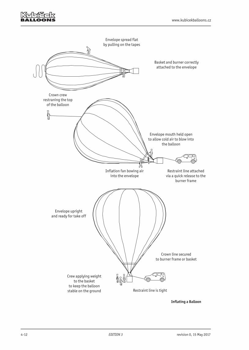
www.kubicekballoons.cz
4-12 EDITION 3 revision 0, 15 May 2017
Envelope spread flat by pulling on the tapes
Basket and burner correctly attached to the envelope
Restraint line attached via a quick release to the
burner frame
Envelope mouth held opento allow cold air to blow into
the balloon
Crown crewrestraning the top
of the balloon
Envelope uprightand ready for take off
Inflation fan bowing airinto the envelope
Crown line securedto burner frame or basket
Crew applying weightto the basket
to keep the balloonstable on the ground
Inflating a Balloon
Restraint line is tight
B.3102 Flight Manual
revision 2, 10 January 2018 >> EDITION 3 << 4-13
4.3.10 Pre-Take-off check
Heating Heat as appropriate to keep the envelope upright and pressurized.Venting Release velcro tabs by pulling the red line at the parachute and paralite, red-white line
at SV, SLV and LV, check function of the venting and correct seal after releasing the line. SV, SLV only Check operation of the deflation mode - open the SV / SLV partially by pulling on the red
line, close by the red-white line.LV only Check operation of the deflation mode - open the LV partially by pulling on the red the
line, close as possible by the red-white line and reset by the white line.Rip panel only Check the correct seal. The locks secured.DS control lines Free to move, not entangled, attached to the envelope carabiner of in the basket, within
pilot‘s reach.RV Check function.Crown line Fixed in pilot‘s vicinity.Envelope No unacceptable damage.Carabiners Closed and locked.Burners All burners working correctly.Pilot flames Correct function of the pilot burner - flame only around the upper part, not blowing from
the lower holes.Fuel system Hoses connected, cylinder turned on as required. No leaks.Radios andInstruments Altimeter correctly set, instruments turned on, thermometer working. Radio checked.Ignition sources Within easy reach.Positioning Ground crew move the basket downwind to the full length of the quick release rope, then
hold the basket on the ground.Map Map(s) showing the intended flight path present.
WARNING Do not attach any objects on to the fuel fittings.
WARNING NO FLIGHT IS PERMITTED if there is a leak in the fuel system or a pilot flame malfunction!
CAUTIONForce required to manipulate the deflation system lines may increase during the balloon operation. Always check that the pilot is able to operate the deflation system.
4.3.11 Passenger Boarding
Instruct passengers to enter the basket with no partitions on its upwind side, and when you use the partitioned bas-kets place them into the compartments so that the weight is distributed evenly. The pilot keeps his or her position close to control lines and most of the fuel tanks.
NOTEAlthough it is possible it is not recommended that a passenger be placed into the pilot compartment inpartitioned baskets.
WARNING Only load passengers when the restrain line is tight.
www.kubicekballoons.cz
4-14 EDITION 3 revision 2, 10 January 2018
4.3.12 Take-off
Basket door (if fitted) Closed and secured on both sides.Balance Balloon in equilibriumBasket area Clear of equipment and peopleBasket check No person or object attached to the outside of the basketPassengers In the landing position for the fast landingPassengers in the seat Sitting in the seat with harness correctly worn and adjusted.(if fitted) Airspace Area around and above the balloon clear of other traffic, safe for climbingGround crew Release the basket graduallyHeat Heat to lift offQuick release Pin removed and then release.Obstacles Clear the obstaclesTime record Note take-off time.Quick release Remove the quick release. Stow the quick release line inside the basket (Y-Type and Mo dified W-Type only).Weather No weather dangerous to the flightPostition lights Deploy and switch on.(if fitted)
WARNING Never use crew pressing down on the basket to build up excess lift before leaving the ground.
CAUTIONDuring taking-off remember to climb at a rate appropriate to the prevailing wind speed and direction toensure safe over-flight of downwind obstructions. Pilot is to face forward.
CAUTION
In windy conditions be aware that the balloon may, even in light wind, on lift off, suffer from ‘false lift’that will be lost as the balloon accelerates to the prevailing wind speed. As ‘false lift’ decreases so it willhave to be replaced by extra burning. ‘False lift’ is the lift generated by the wind blowing over the top ofthe balloon while it is stationary.
NOTE
If, in windy conditions, you chose to inflate the balloon in the shelter of trees upwind pay attention tothe following: - Make sure that the shelter will protect the whole height of the inflated balloon - Make sure that the balloon is securely restrained. - Be aware that as the balloon flies clear of the shelter the envelope may distort and lose lift that will
have to be replaced by burning at once.
NOTE Takeoff for night flights: Carry on the standard procedures, use the portable light when necessary.
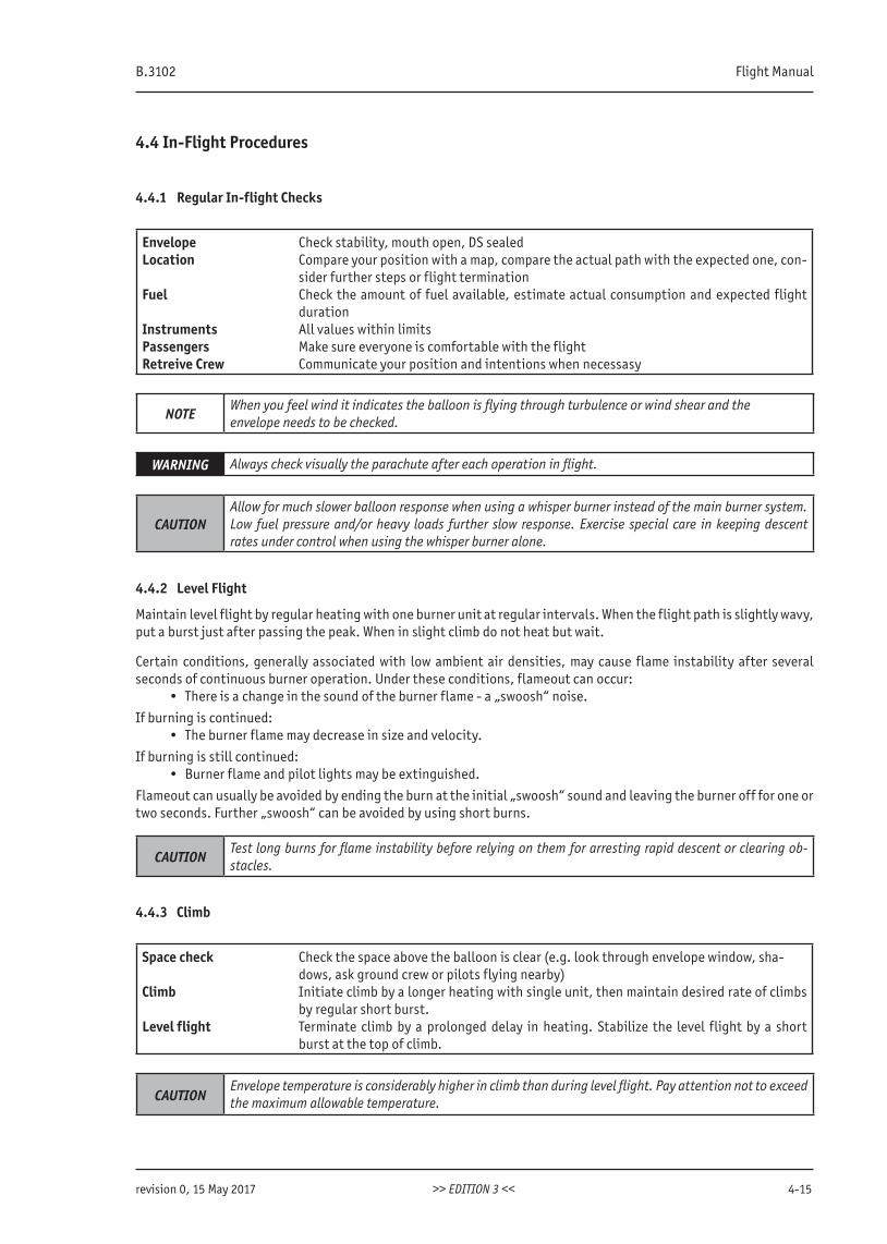
B.3102 Flight Manual
revision 0, 15 May 2017 >> EDITION 3 << 4-15
4.4 In-Flight Procedures
4.4.1 Regular In-flight Checks
Envelope Check stability, mouth open, DS sealedLocation Compare your position with a map, compare the actual path with the expected one, con-
sider further steps or flight terminationFuel Check the amount of fuel available, estimate actual consumption and expected flight
durationInstruments All values within limitsPassengers Make sure everyone is comfortable with the flightRetreive Crew Communicate your position and intentions when necessasy
NOTEWhen you feel wind it indicates the balloon is flying through turbulence or wind shear and theenvelope needs to be checked.
WARNING Always check visually the parachute after each operation in flight.
CAUTIONAllow for much slower balloon response when using a whisper burner instead of the main burner system. Low fuel pressure and/or heavy loads further slow response. Exercise special care in keeping descent rates under control when using the whisper burner alone.
4.4.2 Level Flight
Maintain level flight by regular heating with one burner unit at regular intervals. When the flight path is slightly wavy, put a burst just after passing the peak. When in slight climb do not heat but wait.
Certain conditions, generally associated with low ambient air densities, may cause flame instability after several seconds of continuous burner operation. Under these conditions, flameout can occur:
• There is a change in the sound of the burner flame - a „swoosh“ noise.
If burning is continued:• The burner flame may decrease in size and velocity.
If burning is still continued:• Burner flame and pilot lights may be extinguished.
Flameout can usually be avoided by ending the burn at the initial „swoosh“ sound and leaving the burner off for one or two seconds. Further „swoosh“ can be avoided by using short burns.
CAUTIONTest long burns for flame instability before relying on them for arresting rapid descent or clearing ob-stacles.
4.4.3 Climb
Space check Check the space above the balloon is clear (e.g. look through envelope window, sha- dows, ask ground crew or pilots flying nearby)Climb Initiate climb by a longer heating with single unit, then maintain desired rate of climbs
by regular short burst.Level flight Terminate climb by a prolonged delay in heating. Stabilize the level flight by a short
burst at the top of climb.
CAUTIONEnvelope temperature is considerably higher in climb than during level flight. Pay attention not to exceed the maximum allowable temperature.
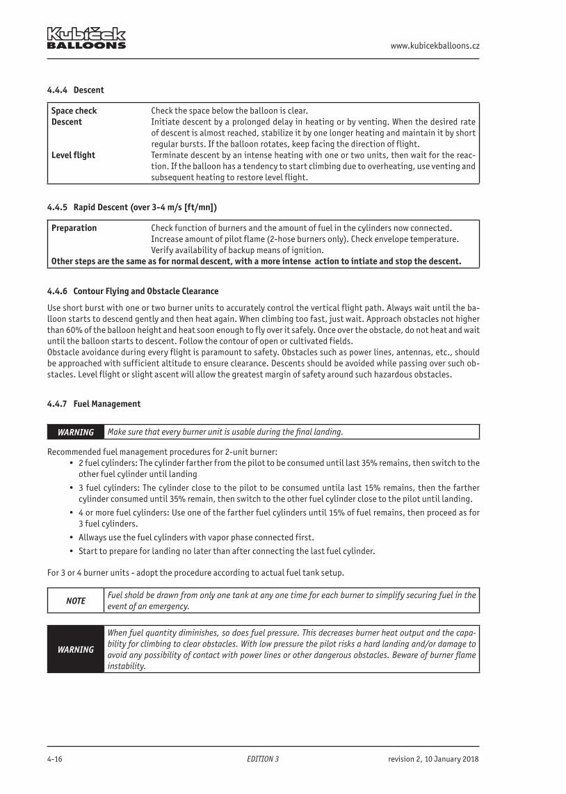
www.kubicekballoons.cz
4-16 EDITION 3 revision 2, 10 January 2018
4.4.4 Descent
Space check Check the space below the balloon is clear.Descent Initiate descent by a prolonged delay in heating or by venting. When the desired rate
of descent is almost reached, stabilize it by one longer heating and maintain it by short regular bursts. If the balloon rotates, keep facing the direction of flight.
Level flight Terminate descent by an intense heating with one or two units, then wait for the reac-tion. If the balloon has a tendency to start climbing due to overheating, use venting and subsequent heating to restore level flight.
4.4.5 Rapid Descent (over 3-4 m/s [ft/mn])
Preparation Check function of burners and the amount of fuel in the cylinders now connected. Increase amount of pilot flame (2-hose burners only). Check envelope temperature. Verify availability of backup means of ignition.Other steps are the same as for normal descent, with a more intense action to intiate and stop the descent.
4.4.6 Contour Flying and Obstacle Clearance
Use short burst with one or two burner units to accurately control the vertical flight path. Always wait until the ba-lloon starts to descend gently and then heat again. When climbing too fast, just wait. Approach obstacles not higher than 60% of the balloon height and heat soon enough to fly over it safely. Once over the obstacle, do not heat and wait until the balloon starts to descent. Follow the contour of open or cultivated fields.Obstacle avoidance during every flight is paramount to safety. Obstacles such as power lines, antennas, etc., should be approached with sufficient altitude to ensure clearance. Descents should be avoided while passing over such ob-stacles. Level flight or slight ascent will allow the greatest margin of safety around such hazardous obstacles.
4.4.7 Fuel Management
WARNING Make sure that every burner unit is usable during the final landing.
Recommended fuel management procedures for 2-unit burner:• 2 fuel cylinders: The cylinder farther from the pilot to be consumed until last 35% remains, then switch to the
other fuel cylinder until landing
• 3 fuel cylinders: The cylinder close to the pilot to be consumed untila last 15% remains, then the farther cylinder consumed until 35% remain, then switch to the other fuel cylinder close to the pilot until landing.
• 4 or more fuel cylinders: Use one of the farther fuel cylinders until 15% of fuel remains, then proceed as for 3 fuel cylinders.
• Allways use the fuel cylinders with vapor phase connected first.
• Start to prepare for landing no later than after connecting the last fuel cylinder.
For 3 or 4 burner units - adopt the procedure according to actual fuel tank setup.
NOTEFuel shold be drawn from only one tank at any one time for each burner to simplify securing fuel in the event of an emergency.
WARNING
When fuel quantity diminishes, so does fuel pressure. This decreases burner heat output and the capa-bility for climbing to clear obstacles. With low pressure the pilot risks a hard landing and/or damage to avoid any possibility of contact with power lines or other dangerous obstacles. Beware of burner flame instability.
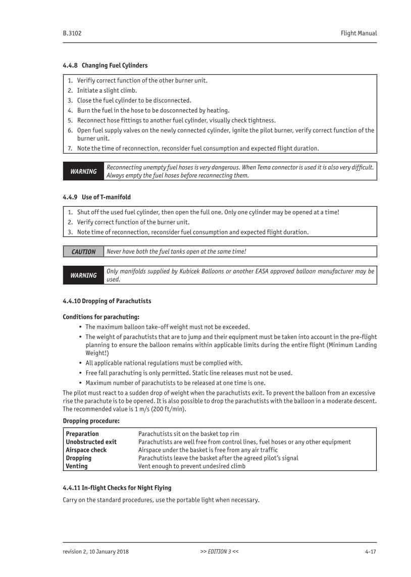
B.3102 Flight Manual
revision 2, 10 January 2018 >> EDITION 3 << 4-17
4.4.8 Changing Fuel Cylinders
1. Verifiy correct function of the other burner unit.
2. Initiate a slight climb.
3. Close the fuel cylinder to be disconnected.
4. Burn the fuel in the hose to be dosconnected by heating.
5. Reconnect hose fittings to another fuel cylinder, visually check tightness.
6. Open fuel supply valves on the newly connected cylinder, ignite the pilot burner, verify correct function of the burner unit.
7. Note the time of reconnection, reconsider fuel consumption and expected flight duration.
WARNINGReconnecting unempty fuel hoses is very dangerous. When Tema connector is used it is also very difficult. Always empty the fuel hoses before reconnecting them.
4.4.9 Use of T-manifold
1. Shut off the used fuel cylinder, then open the full one. Only one cylinder may be opened at a time!
2. Verify correct function of the burner unit.
3. Note time of reconnection, reconsider fuel consumption and expected flight duration.
CAUTION Never have both the fuel tanks open at the same time!
WARNINGOnly manifolds supplied by Kubicek Balloons or another EASA approved balloon manufacturer may be used.
4.4.10 Dropping of Parachutists
Conditions for parachuting:• The maximum balloon take-off weight must not be exceeded.
• The weight of parachutists that are to jump and their equipment must be taken into account in the pre-flight planning to ensure the balloon remains within applicable limits during the entire flight (Minimum Landing Weight!)
• All applicable national regulations must be complied with.
• Free fall parachuting is only permitted. Static line releases must not be used.
• Maximum number of parachutists to be released at one time is one.
The pilot must react to a sudden drop of weight when the parachutists exit. To prevent the balloon from an excessiverise the parachute is to be opened. It is also possible to drop the parachutists with the balloon in a moderate descent.The recommended value is 1 m/s (200 ft/min).
Dropping procedure:
Preparation Parachutists sit on the basket top rimUnobstructed exit Parachutists are well free from control lines, fuel hoses or any other equipmentAirspace check Airspace under the basket is free from any air trafficDropping Parachutists leave the basket after the agreed pilot’s signalVenting Vent enough to prevent undesired climb
4.4.11 In-flight Checks for Night Flying
Carry on the standard procedures, use the portable light when necessary.
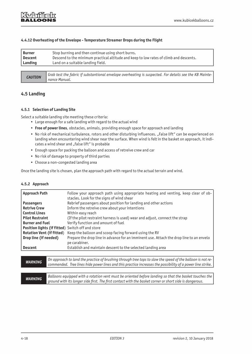
www.kubicekballoons.cz
4-18 EDITION 3 revision 2, 10 January 2018
4.4.12 Overheating of the Envelope - Temperature Streamer Drops during the Flight
Burner Stop burning and then continue using short burns.Descent Descend to the minimum practical altitude and keep to low rates of climb and descents.Landing Land on a suitable landing field.
CAUTIONGrab test the fabric if substantional envelope overheating is suspected. For details see the KB Mainte-nance Manual.
4.5 Landing
4.5.1 Selection of Landing Site
Select a suitable landing site meeting these criteria:• Large enough for a safe landing with regard to the actual wind
• Free of power lines, obstacles, animals, providing enough space for approach and landing
• No risk of mechanical turbulence, rotors and other disturbing influences. „False lift“ can be experienced on landing when encountering wind shear near the surface. When wind is felt in the basket on approach, it indi-cates a wind shear and „false lift“ is probable
• Enough space for packing the balloon and access of retreive crew and car
• No risk of damage to property of third parties
• Choose a non-congested landing area
Once the landing site is chosen, plan the approach path with regard to the actual terrain and wind.
4.5.2 Approach
Approach Path Follow your approach path using appropriate heating and venting, keep clear of ob-stacles. Look for the signs of wind shear
Passengers Rebrief passengers about position for landing and other actionsRetrive Crew Inform the retreive crew about your intentionsControl Lines Within easy reachPilot Restraint (If the pilot restraint harness is used) wear and adjust, connect the strapBurner and Fuel Verify function and amount of fuelPosition lights (if fitted) Switch off and storeRotation Vent (if fitted) Keep the balloon and scoop facing forward using the RVDrop line (if needed) Prepare the drop line in advance for an imminent use. Attach the drop line to an envelo pe carabiner.Descent Establish and maintain descent to the selected landing area
WARNINGOn approach to land the practice of brushing through tree tops to slow the speed of the balloon is not re-commended. Tree lines hide power lines and this practice increases the possibility of a power line strike.
WARNINGBalloons equipped with a rotation vent must be oriented before landing so that the basket touches the ground with its longer side first. The first contact with the basket corner or short side is dangerous.
B.3102 Flight Manual
revision 2, 10 January 2018 >> EDITION 3 << 4-19
WARNING
WIND SHEAR ON LANDING It is critical that pilots recognize wind shear on approach to land. It is the major cause of hard landings, especially with heavily loaded balloons. When the top of the balloon goes through the wind shear, it first gives a lift which cancels the slow descent that the pilot has initiated on his approach. If the pilot does not recognize this phenomena, he will wait for the balloon to descend be-fore firing the burner. The combination of the delay in firing the burner and the sudden loss of the „falselift“ will create a more rapid descent than anticipated. The loss of lift is created when the differential wind on the top of the envelope goes away as the balloon drops below the wind shear and the balloon speed is reduced to the lower wind.
4.5.3 Landing
Final Approach Descend to a height of approximately 1 m (3 ft) above ground, make a final burn to slow the descent if appropriate
Drop Line (if needed) In case the drop line is needed: Check the attachment and drop to the chase crew, if it is safe so.Burner Shutoff Turn off all burners and pilot flames when no further heating is required. Shut off all fuel
supplies on the cylinders and vent all hoses.Venting Pull the red line just prior to touchdownTouchdown Inform passengers just prior to the contact with the groundVenting Keep venting until the balloon stops safely.
WARNINGWhen attaching and dropping the drop line, ensure that it is free from all fuel hoses, control lines and rigging. Do not allow the crew to catch the drop line during its fall. It should hit the ground free of ob-structions.
4.5.4 Actions After Landing
1. All persons remain in the basket.
2. The pilot verifies the terrain is suitable for packing and access of the retrieve crew or consider walking the in-flated balloon to a more convenient place if necessary.
3. Passengers leave basket on pilot’s instructions.
4. Turn the balloon so that the scoop is facing down wind. Detach the crown line. Instruct the crew where to lay the envelope.
5. Open the DS completely by the red line and deflate the envelope. Crown crew pulls the crown line downwind, stabilizing the envelope and helping to lay it in the desired direction, clear of burners and obstacles. Other crew members can help to keep the envelope from draping over trees or bushes and assist it in coming down.
6. Empty the envelope of air by folding it into a long line and expelling the air towards the crown.
4.5.5 Packing of the Envelope
1. Once the envelope lies on the ground, reconnect the aft envelope carabiners to the forward ones and attach them to the outer basket handles.
2. Release the control lines and store them in the envelope.
3. Pull the DS panel to the crown ring.
4. Start pack the envelope into a “sausage” shape from the mouth towards the top, expelling the remaining air-trough the DS aperture. The crown crew holds the DS aperture open if necessary.
5. Pack the crown line and place it on the fabric together with top load tapes.
6. Pack the envelope into the bag starting at the top end. At the mouth the envelope carabiners are to be put into their bag and together with flying wires wrapped into the scoop fabric so that no metal part comes in contact with the envelope fabric.
www.kubicekballoons.cz
4-20 EDITION 3 revision 2, 10 January 2018
CAUTIONIf the envelope is damp or wet it must be dried as soon as possible. Storage when wet can cause severe damage to the envelope and especially its artwork.
4.5.6 Packing of the Bottom End
1. Verify all fuel hoses are vented from remaining fuel.
2. Wait till the burner coils are cooled down.
3. Disconnect them from the fuel cylinder fittings. Detach the burner support rod padding and place hoses conve-niently onto the burner or burner frame. Observe the minimum radius of bend.
4. Detach basket carabiners from the burner frame and put the basket wires through the basket inner handles with all carabiners kept at the ends.
5. Fix the burner units to the burner frame.
6. Remove the burner from the support rods. Place it into its bag, if available, and hang it in the basket.
7. Check that all tank valves are in the closed position.
WARNING Do not vent raw propane. Don‘t use fuel for cooling the coils.
WARNING You can suffer severe burns if you touch the burner coil when it is hot.
CAUTIONAlways vent the fuel hoses and T-manifolds to prevent damage to the hoses. Always keep the minimum hose bend radius 90 mm. See Appendix 5 for guidance.
4.5.7 Loading, Leaving the Landing Site
1. Load all the equipment into the vehicle or onto a trailer and verify nothing is left behind.
2. Secure all the balloon parts to avoid any movement.
3. Record the flight in the balloon log book and pilot’s log book.
4. If necessary, verify and note any damage to the landing site, balloon or retrieve vehicle.
NOTEIt is not advised to transport burners erected (on the basket). As such transport can cause damage to the burner.
WARNING Do not transport any persons in the basket!
4.5.8 Special Cases of Landing
The following cases of landing, although considered normal, require a more careful pilotage compared to normallanding:
Landing onto a Downhill TerrainMake a very gentle touchdown and keep the basket from flipping downhill.
Landing onto an Uphill TerrainMake a very gentle touchdown in a moderate climb.
Landing Just Behind an ObstacleApproach with a level flight path with suffcient distance from the obstacle. In case of a single obstacle keep levelwith its top and do not descent below it. Fly above the obstacle and vent to initiate a steep descent just after passingover it.
WARNING Verify the area behind the obstacle is clear of power lines before initiating a descent!
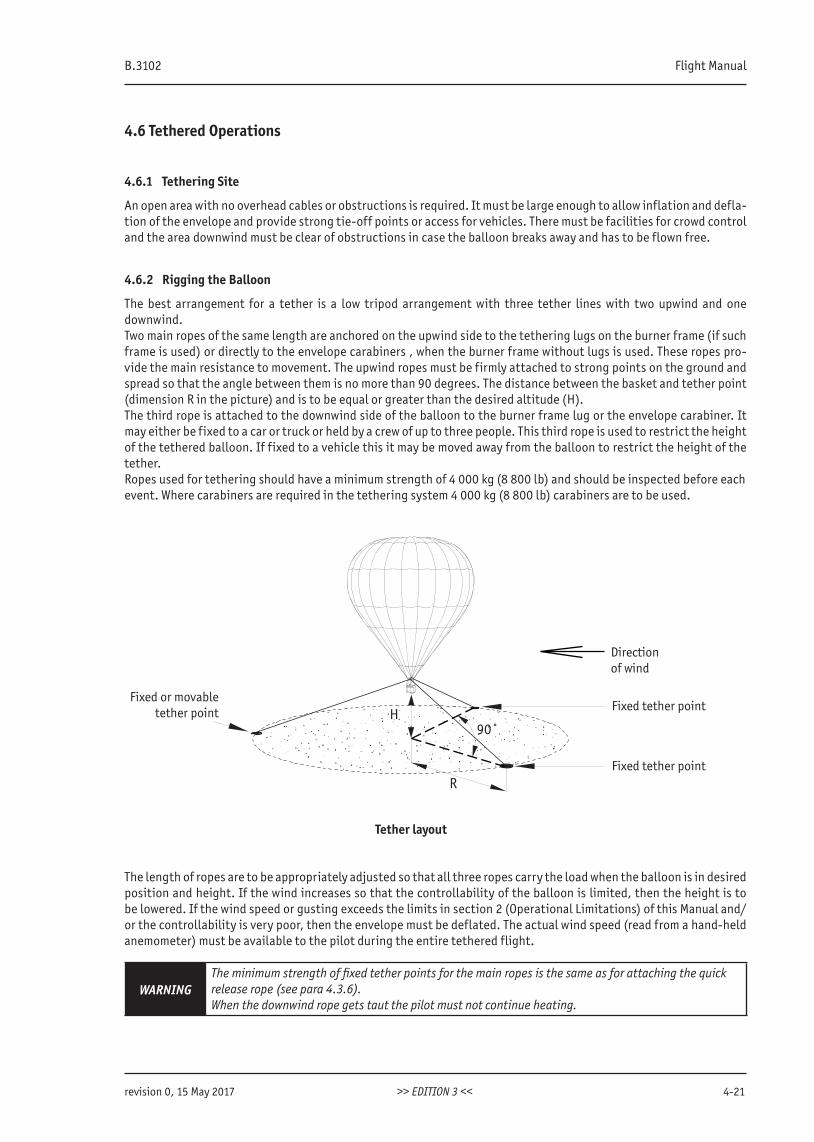
B.3102 Flight Manual
revision 0, 15 May 2017 >> EDITION 3 << 4-21
4.6 Tethered Operations
4.6.1 Tethering Site
An open area with no overhead cables or obstructions is required. It must be large enough to allow inflation and defla-tion of the envelope and provide strong tie-off points or access for vehicles. There must be facilities for crowd controland the area downwind must be clear of obstructions in case the balloon breaks away and has to be flown free.
4.6.2 Rigging the Balloon
The best arrangement for a tether is a low tripod arrangement with three tether lines with two upwind and one downwind.Two main ropes of the same length are anchored on the upwind side to the tethering lugs on the burner frame (if such frame is used) or directly to the envelope carabiners , when the burner frame without lugs is used. These ropes pro-vide the main resistance to movement. The upwind ropes must be firmly attached to strong points on the ground and spread so that the angle between them is no more than 90 degrees. The distance between the basket and tether point (dimension R in the picture) and is to be equal or greater than the desired altitude (H).The third rope is attached to the downwind side of the balloon to the burner frame lug or the envelope carabiner. It may either be fixed to a car or truck or held by a crew of up to three people. This third rope is used to restrict the height of the tethered balloon. If fixed to a vehicle this it may be moved away from the balloon to restrict the height of the tether.Ropes used for tethering should have a minimum strength of 4 000 kg (8 800 lb) and should be inspected before eachevent. Where carabiners are required in the tethering system 4 000 kg (8 800 lb) carabiners are to be used.
90˚H
R
Fixed or movabletether point
Directionof wind
Fixed tether point
Fixed tether point
Tether layout
The length of ropes are to be appropriately adjusted so that all three ropes carry the load when the balloon is in desired position and height. If the wind increases so that the controllability of the balloon is limited, then the height is to be lowered. If the wind speed or gusting exceeds the limits in section 2 (Operational Limitations) of this Manual and/or the controllability is very poor, then the envelope must be deflated. The actual wind speed (read from a hand-held anemometer) must be available to the pilot during the entire tethered flight.
WARNINGThe minimum strength of fixed tether points for the main ropes is the same as for attaching the quickrelease rope (see para 4.3.6).When the downwind rope gets taut the pilot must not continue heating.
www.kubicekballoons.cz
4-22 EDITION 3 revision 0, 15 May 2017
WARNINGThe basket lugs are to be used for quick release attachement during takeoff and must not be used for continuous tethering!
WARNING The quick release must never be used during tethered flight.
WARNINGThe pilot should instruct the crew members to keep spectators away from the basket, tether lines and tie-off points or vehicles. Avoid tethering without effective crowd control. Always consider bystanders as unaware of the risks involved with tethering.
CAUTION The drop line installed in the basket shall not be used as a tethering line.
NOTEBe aware that tethering in windy conditions puts considerable stress on the balloon, tethering equip-ment and tether points. If any of the equipment is suspected to have been overstressed then the balloon must be deflated.
4.7 Refuelling
4.7.1 General Precautions When Dealing With Fuel and Manipulating Fuel Cylinders
WARNINGNo smoking or operation of electrical equipment, or engines within 6 metres of the refuelling operation. Remove all strikers or ignition sources from the basket. Wear leather gloves and have a fire extinguisher readily available. REFUEL OUTDOORS ONLY!
WARNING
Refuelling and any manipulation of fuel cylinders must be carried out with extra care and by knowledge-able personnel only in accordance with standard practices for handling propane, and supervised by the pilot.Propane, butane and LPG are highly flamable. The following instructions must be followed and any nati-onal regulations fulfilled.
Dos: Wear strong protective gloves as a protection from possible burns or frostbites from evaporating fuel. The gloves must also allow for an easy manipulation with fittings and valves.
Avoid wearing clothes made of synthetic material to reduce the risk of static spark. At least one fire extinguisher must be available. The fuel cylinders and supply source must be electrically grounded when refueling. Keep away all sources of fire, heat, ignition, lighters, matches, smoking, naked lights, live electric or radio equipment, or mobile telephones. Keep away all persons not directly involved in the refueling.
Don’ts: Do not refuel cylinders in the basket. Do not refuel cylinders in an enclosed area (like a closed trailer or a van) or near any hollows, pits,
or anywhere the vapor could accumulate. Do not refuel more than one cylinder at a time.
B.3102 Flight Manual
revision 2, 10 January 2018 >> EDITION 3 << 4-23
4.7.2 Refuelling Procedure
1. Connect the cylinder with the refuelling hose.
2. Open the maxfill valve on the fuel cylinder just enough to hear the gas escaping.
3. Open the liquid valve on the cylinder.
4. Open the supply valve on the source tank.
5. Start the pump (if fitted).
6. When the flow from the maxfill valve changes from vapor to liquid, turn the liquid valve on the cylinder off im-mediately. Close the maxfill valve and turn the pump off.
7. Vent the refuelling hose and empty the liquid valve on the cylinder by depressing its central self-sealing spigot.
WARNINGDo not overfill the fuel tank at any case! Do not exceed the safe working pressure specified in the fuel cylinder index plate!
WARNINGDo not fill fuel tanks or open the liquid level gauge valve with tanks in a polyethylene basket or wicker basket which has been lined with any material which would restrict airflow through the basket. Failure to heed this warning may result in serious injury caused by a flash fire.
NOTE Filling by weight should not exceed 0.42 kg/l of the water capacity. See Chapter 8.
4.7.3 Pressurisation of Fuel Cylinders
In order to increase fuel pressure in cold conditions fuel cylinders may be pressurised with nitrogen.The nitrogen must be supplied from a regulated source providing a pressure of between 0 - 10 bar (0-145 psi) and an indication of the pressure in the fuel cylinder.The nitrogen must be handled in accordance with the supplier‘s instructions.Nitrogen is supplied to the fuel cylinders that have been previously fueled. Nitrogen is supplied through the liquid take off until the desired pressure is reached.
WARNING No gas other than nitrogen may be used for pressurisation! Never use air or oxygen!
CAUTIONThe maximum fuel cylinder pressure after pressurizing must not be greater than 10 bar (145 psi).The maximum fuel cylinder pressure must not be greater than 7 bar (100 psi) if the cylinder is to be stored in a pressurised state.
If vapor pilot lights are to be used, then sufficient master cylinders must be left unpressurized and identifiable so that nitrogen is not fed to the pilot lights. Cylinders pressurized with nitrogen should not be used for vapor pilot lights.Fuel cylinders should be pressurized shortly before they are to be used and labeled to indicate that they are pressuri-zed. If they are not used soon after pressurizing then the pressure in these cylinders should be reduced to a maximumof 7 bar (100 psi) by opening the maxfill valve. When venting in this way the same precautions are to be taken as for refueling fuel cylinders.In addition to the above instructions , the applicable national and local requirement for safety, handling and storageof pressurized gases and pressure cylinders are to be observed.

www.kubicekballoons.cz
4-24 EDITION 3 revision 0, 15 May 2017
INTENTIONALLY LEFT BLANK
B.3102 Flight Manual
revision 0, 15 May 2017 >> EDITION 3 << 5-1
SECTION 5 - WEIGHT
5.1 IntroductionThis section provides guidance for establishing the flight weight range within which the balloon can be safely flown. The balloon’s lifting capacity is mainly affected by ambient air temperature and flight altitude. Higher ambient air temperature and higher altitude lead to lower lifting capacity and vice versa.
5.2 Loading Chart and TableBefore each flight the take-off mass of the balloon must be calculated to see that it does not exceed the Total Permi-tted Lift.The Total Permitted Lift depends on:
• envelope volume
• flight altitude
• ambient air temperature
NOTE When exceeding the Total Permitted Lift in flight the temperature streamer is likely to drop.
NOTE Weight limitations specified in Chapter 2. must be observed as well.
5.2.1 Instruction for Determining Allowable Weight Range Using the Loading Chart and Table
1. Find the actual take-off weight as a sum of the weight of the entire balloon, persons in the basket, fuel and all other equipment to be carried on board. The weight of the air inside the balloon shall not be considered.
2. Decide on the maximum desired flight altitude and determine the air temperature at this altitude. If the tempera-ture is not known, assume a standard temperature decrease of 0.65°C/100m (3.56°F/1000ft).
3. Read the number of Lift Units per 1000 cubic feet from the Loading Chart. Start from the actual altitude tempera-ture on the horizontal axis, go vertically until reaching the curve for the desired altitude. From this intersection continue horizontally to read the actual value of Lift Units.
4. In the Loading Table find the appropriate value of the Total Permitted Lift.
5. Compare the take-off weight to the Total Permitted Lift and MTOW (or RMTOW if applicable). The balloon can only be flown if the actual take-off weight remains within these limits.
NOTE
The Loading Chart and Loading Table are based on static lift with the maximum operational allowed en-velope’s internal temperature that allows for moderate rate of climb without overheating the envelope.When flying a balloon at, or close to, its maximum lift care must be taken not to overheat the envelope by intense heating.
CAUTIONIn addition to the above weight assumptions the maximum loading capacity of the basket must be ob-served as well! See section 2.10 of this manual.
5.3 Flying in a Temperature InversionThe Loading Chart presumes that the temperature decreases with height according to ISA. When the temperature increases with height instead of decreasing this is called a temperature inversion. A temperature inversion happens frequently in the early morning, particularly if there has been a clear sky overnight.To prevent overheating the balloon when flying in an inversion, enter the chart with either the anticipated tempera-ture at your launch height at mid day or the known temperature at a specific height above the inversion.
www.kubicekballoons.cz
5-2 EDITION 3 revision 0, 15 May 2017
5.4 Sample CalculationsDot-and-dashed line shows the following sample calculation.
Example• Your balloon is a BB20 (71 200 cu ft). Calculate the take-off weight as a sum of the weight if the complete
balloon, fuel, occupants and equipment.
• The balloon will be flown at a maximum altitude of 6 000 ft and your weather briefing has told you that the temperature at this height will be 6°C.
• Enter the Loading Chart at 6°C on the bottom line and go up until you reach the 6 000 ft curve. From this point travel left parallel to the horizontal lines until you reach the left scale at 16.5.
• Decide whether you want an answer in either kg or lb and enter the appropriate Loading Table with 16.5 along the top line. You will have to interpolate between 16 and 17. Go vertically downwards until you reach the ho-rizontal line for a BB20. The result is 533 kg (1175 lb).
• The take-off weight must remain below 533 kg (1175 lb) and MTOW for the BB20 model. If yes, the balloon can be flown in the actual condition. w
NOTE Pay particular attention to observing the MTOW at low temperatures. In no case may the intersection of temperature and desired flight altitude lie above the chart. This would lead to exceeding the MTOW.
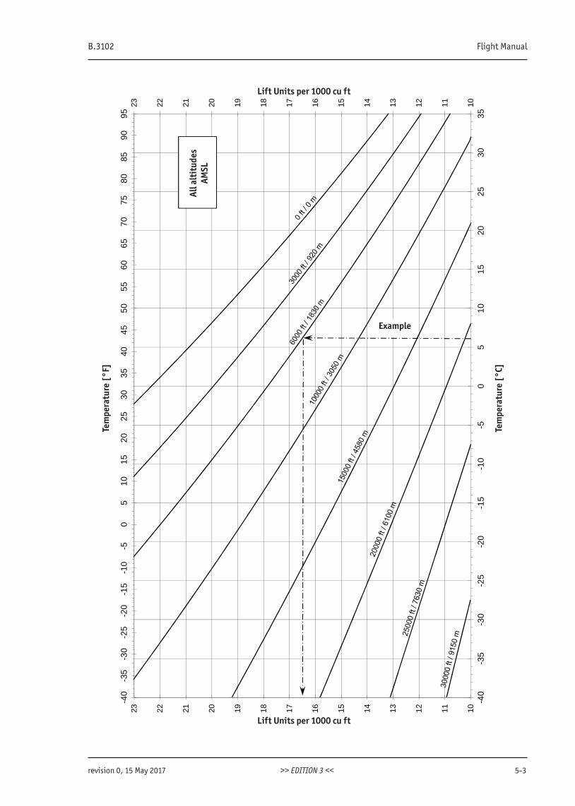
B.3102 Flight Manual
revision 0, 15 May 2017 >> EDITION 3 << 5-3
1011121314151617181920212223-4
0-3
5-3
0-2
5-2
0-1
5-1
0-5
05
1015
2025
3035
4045
5055
6065
7075
8085
9095
1011121314151617181920212223
-40
-35
-30
-25
-20
-15
-10
-50
510
1520
2530
35
Lift Units per 1000 cu ft
Tem
per
atu
re [
°F]
Lift Units per 1000 cu ft
Tem
per
atu
re [
°C]
Example
All a
ltit
udes
AMSL
Lift Units per 1000 cu ft
Lift Units per 1000 cu ft
Example
Tem
pera
ture
[°C
]
Tem
pera
ture
[°F
]
All a
ltit
udes
AMSL
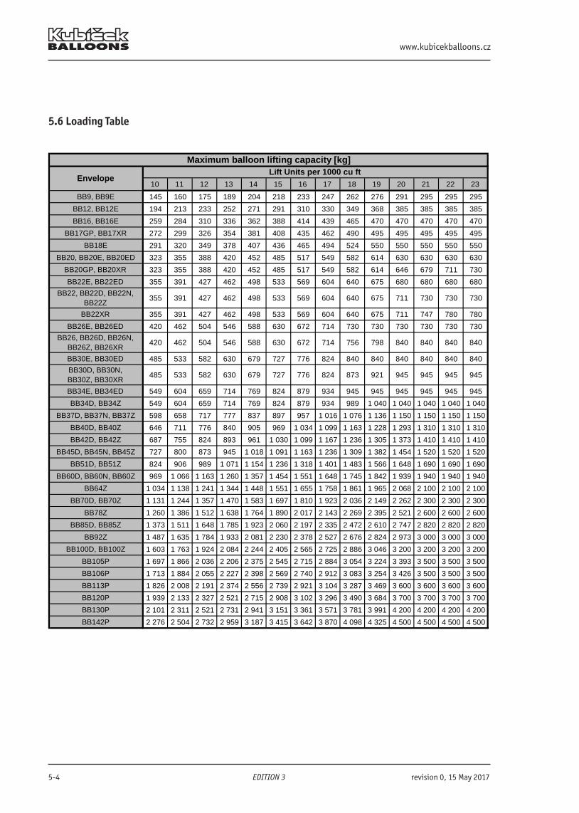
www.kubicekballoons.cz
5-4 EDITION 3 revision 0, 15 May 2017
5.6 Loading Table
10 11 12 13 14 15 16 17 18 19 20 21 22 23
BB9, BB9E 145 160 175 189 204 218 233 247 262 276 291 295 295 295
BB12, BB12E 194 213 233 252 271 291 310 330 349 368 385 385 385 385
BB16, BB16E 259 284 310 336 362 388 414 439 465 470 470 470 470 470
BB17GP, BB17XR 272 299 326 354 381 408 435 462 490 495 495 495 495 495
BB18E 291 320 349 378 407 436 465 494 524 550 550 550 550 550
BB20, BB20E, BB20ED 323 355 388 420 452 485 517 549 582 614 630 630 630 630
BB20GP, BB20XR 323 355 388 420 452 485 517 549 582 614 646 679 711 730
BB22E, BB22ED 355 391 427 462 498 533 569 604 640 675 680 680 680 680
BB22, BB22D, BB22N, BB22Z
355 391 427 462 498 533 569 604 640 675 711 730 730 730
BB22XR 355 391 427 462 498 533 569 604 640 675 711 747 780 780
BB26E, BB26ED 420 462 504 546 588 630 672 714 730 730 730 730 730 730
BB26, BB26D, BB26N, BB26Z, BB26XR
420 462 504 546 588 630 672 714 756 798 840 840 840 840
BB30E, BB30ED 485 533 582 630 679 727 776 824 840 840 840 840 840 840
BB30D, BB30N, BB30Z, BB30XR
485 533 582 630 679 727 776 824 873 921 945 945 945 945
BB34E, BB34ED 549 604 659 714 769 824 879 934 945 945 945 945 945 945
BB34D, BB34Z 549 604 659 714 769 824 879 934 989 1 040 1 040 1 040 1 040 1 040
BB37D, BB37N, BB37Z 598 658 717 777 837 897 957 1 016 1 076 1 136 1 150 1 150 1 150 1 150
BB40D, BB40Z 646 711 776 840 905 969 1 034 1 099 1 163 1 228 1 293 1 310 1 310 1 310
BB42D, BB42Z 687 755 824 893 961 1 030 1 099 1 167 1 236 1 305 1 373 1 410 1 410 1 410
BB45D, BB45N, BB45Z 727 800 873 945 1 018 1 091 1 163 1 236 1 309 1 382 1 454 1 520 1 520 1 520
BB51D, BB51Z 824 906 989 1 071 1 154 1 236 1 318 1 401 1 483 1 566 1 648 1 690 1 690 1 690
BB60D, BB60N, BB60Z 969 1 066 1 163 1 260 1 357 1 454 1 551 1 648 1 745 1 842 1 939 1 940 1 940 1 940
BB64Z 1 034 1 138 1 241 1 344 1 448 1 551 1 655 1 758 1 861 1 965 2 068 2 100 2 100 2 100
BB70D, BB70Z 1 131 1 244 1 357 1 470 1 583 1 697 1 810 1 923 2 036 2 149 2 262 2 300 2 300 2 300
BB78Z 1 260 1 386 1 512 1 638 1 764 1 890 2 017 2 143 2 269 2 395 2 521 2 600 2 600 2 600
BB85D, BB85Z 1 373 1 511 1 648 1 785 1 923 2 060 2 197 2 335 2 472 2 610 2 747 2 820 2 820 2 820
BB92Z 1 487 1 635 1 784 1 933 2 081 2 230 2 378 2 527 2 676 2 824 2 973 3 000 3 000 3 000
BB100D, BB100Z 1 603 1 763 1 924 2 084 2 244 2 405 2 565 2 725 2 886 3 046 3 200 3 200 3 200 3 200
BB105P 1 697 1 866 2 036 2 206 2 375 2 545 2 715 2 884 3 054 3 224 3 393 3 500 3 500 3 500
BB106P 1 713 1 884 2 055 2 227 2 398 2 569 2 740 2 912 3 083 3 254 3 426 3 500 3 500 3 500
BB113P 1 826 2 008 2 191 2 374 2 556 2 739 2 921 3 104 3 287 3 469 3 600 3 600 3 600 3 600
BB120P 1 939 2 133 2 327 2 521 2 715 2 908 3 102 3 296 3 490 3 684 3 700 3 700 3 700 3 700
BB130P 2 101 2 311 2 521 2 731 2 941 3 151 3 361 3 571 3 781 3 991 4 200 4 200 4 200 4 200
BB142P 2 276 2 504 2 732 2 959 3 187 3 415 3 642 3 870 4 098 4 325 4 500 4 500 4 500 4 500
Maximum balloon lifting capacity [kg]
EnvelopeLift Units per 1000 cu ft
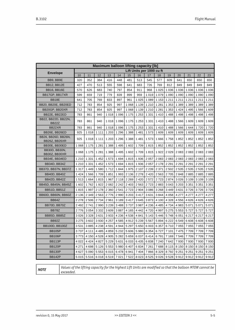
B.3102 Flight Manual
revision 0, 15 May 2017 >> EDITION 3 << 5-5
10 11 12 13 14 15 16 17 18 19 20 21 22 23
BB9, BB9E 320 352 384 416 448 481 513 545 577 609 641 650 650 650
BB12, BB12E 427 470 513 555 598 641 683 726 769 812 849 849 849 849
BB16, BB16E 570 626 683 740 797 854 911 968 1 025 1 036 1 036 1 036 1 036 1 036
BB17GP, BB17XR 599 659 719 779 839 899 959 1 019 1 079 1 090 1 090 1 090 1 090 1 090
BB18E 641 705 769 833 897 961 1 025 1 089 1 153 1 211 1 211 1 211 1 211 1 211
BB20, BB20E, BB20ED 712 783 854 925 997 1 068 1 139 1 210 1 281 1 353 1 389 1 389 1 389 1 389
BB20GP, BB20XR 712 783 854 925 997 1 068 1 139 1 210 1 281 1 353 1 424 1 495 1 566 1 609
BB22E, BB22ED 783 861 940 1 018 1 096 1 175 1 253 1 331 1 410 1 488 1 498 1 498 1 498 1 498
BB22, BB22D, BB22N, BB22Z
783 861 940 1 018 1 096 1 175 1 253 1 331 1 410 1 488 1 566 1 609 1 609 1 609
BB22XR 783 861 940 1 018 1 096 1 175 1 253 1 331 1 410 1 488 1 566 1 644 1 720 1 720
BB26E, BB26ED 925 1 018 1 111 1 203 1 296 1 388 1 481 1 573 1 609 1 609 1 609 1 609 1 609 1 609
BB26, BB26D, BB26N, BB26Z, BB26XR
925 1 018 1 111 1 203 1 296 1 388 1 481 1 573 1 666 1 758 1 852 1 852 1 852 1 852
BB30E, BB30ED 1 068 1 175 1 281 1 388 1 495 1 602 1 709 1 815 1 852 1 852 1 852 1 852 1 852 1 852
BB30D, BB30N, BB30Z, BB30XR
1 068 1 175 1 281 1 388 1 495 1 602 1 709 1 815 1 922 2 029 2 083 2 083 2 083 2 083
BB34E, BB34ED 1 210 1 331 1 452 1 573 1 694 1 815 1 936 2 057 2 083 2 083 2 083 2 083 2 083 2 083
BB34D, BB34Z 1 210 1 331 1 452 1 573 1 694 1 815 1 936 2 057 2 178 2 291 2 291 2 291 2 291 2 291
BB37D, BB37N, BB37Z 1 317 1 449 1 580 1 712 1 844 1 975 2 107 2 239 2 371 2 502 2 535 2 535 2 535 2 535
BB40D, BB40Z 1 424 1 566 1 709 1 851 1 993 2 136 2 278 2 420 2 563 2 705 2 848 2 885 2 885 2 885
BB42D, BB42Z 1 513 1 664 1 815 1 967 2 118 2 269 2 420 2 572 2 723 2 874 3 026 3 109 3 109 3 109
BB45D, BB45N, BB45Z 1 602 1 762 1 922 2 082 2 242 2 403 2 563 2 723 2 883 3 043 3 203 3 351 3 351 3 351
BB51D, BB51Z 1 815 1 997 2 178 2 360 2 541 2 723 2 904 3 086 3 268 3 449 3 631 3 726 3 726 3 726
BB60D, BB60N, BB60Z 2 136 2 349 2 563 2 776 2 990 3 203 3 417 3 631 3 844 4 058 4 277 4 277 4 277 4 277
BB64Z 2 278 2 506 2 734 2 961 3 189 3 417 3 645 3 873 4 100 4 328 4 556 4 626 4 626 4 626
BB70D, BB70Z 2 492 2 741 2 990 3 239 3 488 3 737 3 987 4 236 4 485 4 734 4 983 5 071 5 071 5 071
BB78Z 2 776 3 054 3 332 3 609 3 887 4 165 4 442 4 720 4 997 5 275 5 553 5 727 5 727 5 727
BB85D, BB85Z 3 026 3 328 3 631 3 933 4 236 4 538 4 841 5 143 5 446 5 748 6 051 6 217 6 217 6 217
BB92Z 3 275 3 602 3 930 4 257 4 585 4 912 5 239 5 567 5 894 6 222 6 549 6 608 6 608 6 608
BB100D, BB100Z 3 531 3 885 4 238 4 591 4 944 5 297 5 650 6 003 6 357 6 710 7 055 7 055 7 055 7 055
BB105P 3 737 4 111 4 485 4 859 5 232 5 606 5 980 6 354 6 727 7 101 7 475 7 709 7 709 7 709
BB106P 3 773 4 150 4 528 4 905 5 282 5 659 6 037 6 414 6 791 7 169 7 546 7 709 7 709 7 709
BB113P 4 022 4 424 4 827 5 229 5 631 6 033 6 435 6 838 7 240 7 642 7 930 7 930 7 930 7 930
BB120P 4 271 4 698 5 126 5 553 5 980 6 407 6 834 7 261 7 688 8 115 8 150 8 150 8 150 8 150
BB130P 4 627 5 090 5 553 6 015 6 478 6 941 7 404 7 866 8 329 8 792 9 251 9 251 9 251 9 251
BB142P 5 015 5 516 6 018 6 519 7 021 7 522 8 023 8 525 9 026 9 528 9 912 9 912 9 912 9 912
Maximum balloon lifting capacity [lb]
EnvelopeLift Units per 1000 cu ft
NOTE Values of the lifting capacity for the highest Lift Units are modified so that the balloon MTOW cannot be exceeded.

www.kubicekballoons.cz
5-6 EDITION 3 revision 0, 15 May 2017
INTENTIONALLY LEFT BLANK
B.3102 Flight Manual
revision 0, 15 May 2017 >> EDITION 3 << 6-1
SECTION 6 - BALLOON AND SYSTEMS DESCRIPTION
6.1 IntroductionThis section provides description of the standard component parts and assemblies that make up the balloon system.A complete list of envelopes, baskets and burners is provided in Section 8.The approved combination of equipment is provided in Section 2.
6.2 EnvelopesEnvelopes are of sewn construction made either from polyester or polyamide fabric and a system of load tapes. Thefabric is coated to be airtight. Vertical load tapes take the load from the basket. At the top the vertical load tapesare secured to the crown ring, at the lower end there is a loop to which stainless steel or kevlar flying wires carryingthe basket are attached. Where the flying wire and load tape loop are joined, they are covered by a protective sleeve.horizontal load tapes act as rip-stoppers. The envelope mouth and scoop panels are made from nomex fire resistantfabric.The envelopes are always fitted with a deflation system that provides for a controlled venting of hot air during flightand landing.Each envelope is also equipped with a crown line connected to the crown ring . The crown line is used to control theenvelope during inflation and deflation.All envelopes also have a temperature streamer and a tempilabel to indicate the maximum temperature.The envelope can be fitted with a rotation vent which allows for a controlled rotation of the entire balloon duringflight and for its proper orientation when landing.
6.3 Envelope Models
6.3.1 Natural Shaped Envelopes
The BB type includes a variety of models differing in size, general geometry, orientation of the fabric, number of go-res, their curvature and most suitable use. The envelopes models designated O, E, N, Z, GP, XR, P, D and ED.A full description of envelope models is found at Kubicek Balloon’s website www.kubicekballoons.eu/envelopes. Thecontrols of envelope Deflation systems are the same, irrespective of the model.Some envelopes can be equipped with inflatable appendices, which can be equipped with deflation openings.
6.3.2 Special Shapes
The special shaped envelopes (type BB-S) are typically made to replicate products or characters. Each model has itsown supplement to this Manual which states its description, limitations and other possible peculiarities.
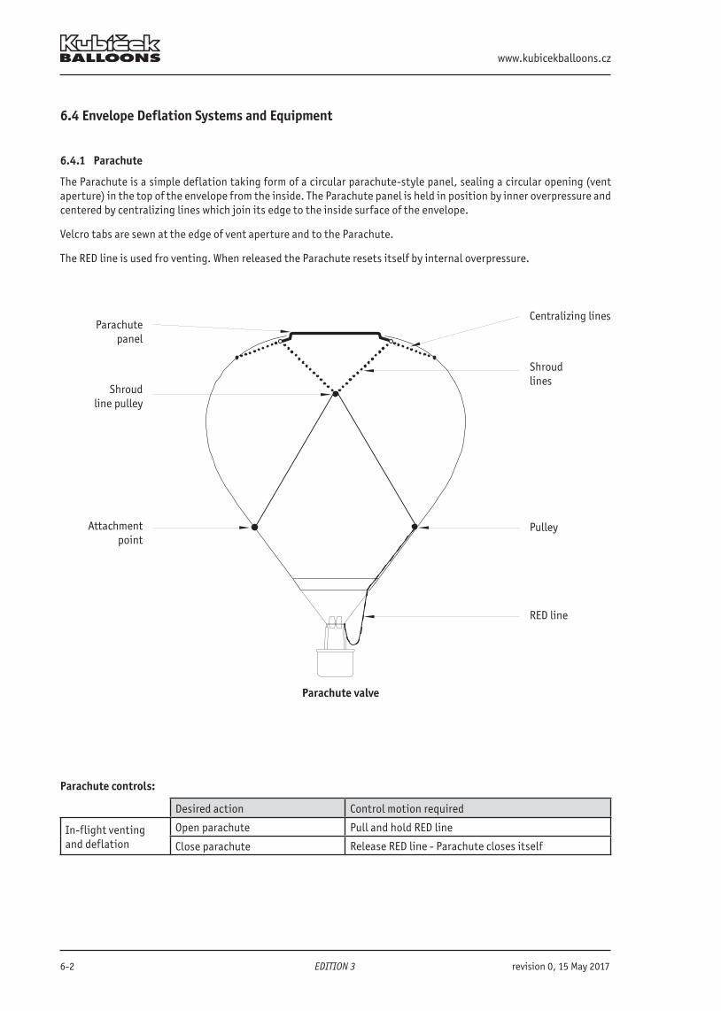
www.kubicekballoons.cz
6-2 EDITION 3 revision 0, 15 May 2017
6.4 Envelope Deflation Systems and Equipment
6.4.1 Parachute
The Parachute is a simple deflation taking form of a circular parachute-style panel, sealing a circular opening (vent aperture) in the top of the envelope from the inside. The Parachute panel is held in position by inner overpressure and centered by centralizing lines which join its edge to the inside surface of the envelope.
Velcro tabs are sewn at the edge of vent aperture and to the Parachute.
The RED line is used fro venting. When released the Parachute resets itself by internal overpressure.
Parachute valve
Parachutepanel
Centralizing lines
Shroudline pulley
Shroudlines
Attachment point
Pulley
RED line
Parachute controls:
Desired action Control motion required
In-flight ventingand deflation
Open parachute Pull and hold RED line
Close parachute Release RED line - Parachute closes itself
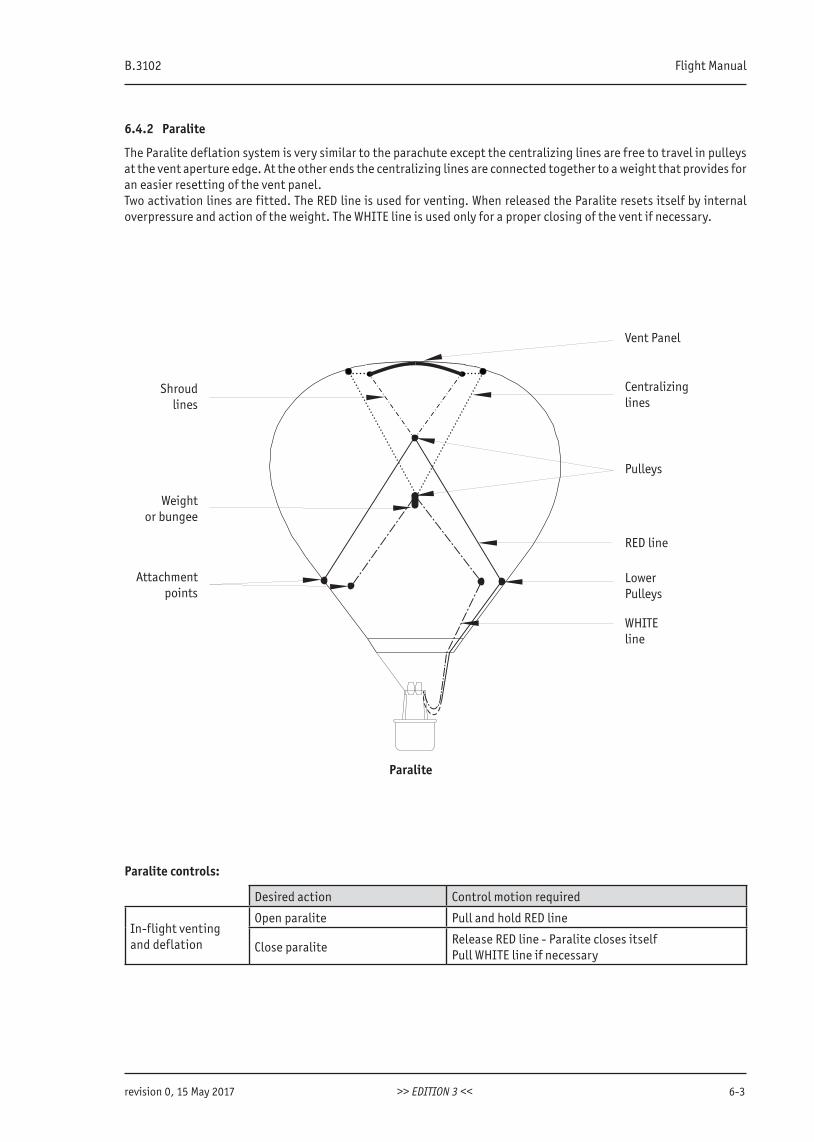
B.3102 Flight Manual
revision 0, 15 May 2017 >> EDITION 3 << 6-3
6.4.2 Paralite
The Paralite deflation system is very similar to the parachute except the centralizing lines are free to travel in pulleys at the vent aperture edge. At the other ends the centralizing lines are connected together to a weight that provides foran easier resetting of the vent panel.Two activation lines are fitted. The RED line is used for venting. When released the Paralite resets itself by internal overpressure and action of the weight. The WHITE line is used only for a proper closing of the vent if necessary.
Shroudlines
Attachmentpoints
Vent Panel
Centralizinglines
Pulleys
RED line
LowerPulleys
WHITEline
Paralite
Weightor bungee
Paralite controls:
Desired action Control motion required
In-flight ventingand deflation
Open paralite Pull and hold RED line
Close paraliteRelease RED line - Paralite closes itselfPull WHITE line if necessary
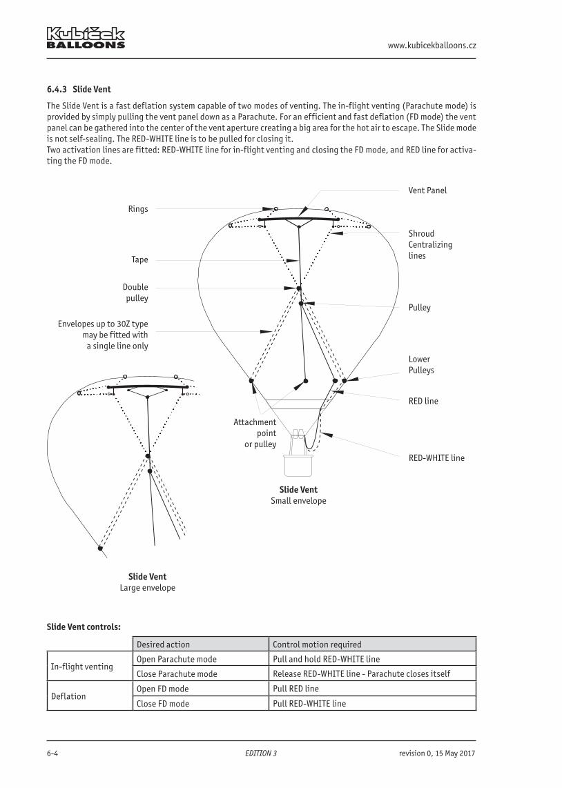
www.kubicekballoons.cz
6-4 EDITION 3 revision 0, 15 May 2017
6.4.3 Slide Vent
The Slide Vent is a fast deflation system capable of two modes of venting. The in-flight venting (Parachute mode) is provided by simply pulling the vent panel down as a Parachute. For an efficient and fast deflation (FD mode) the ventpanel can be gathered into the center of the vent aperture creating a big area for the hot air to escape. The Slide mode is not self-sealing. The RED-WHITE line is to be pulled for closing it.Two activation lines are fitted: RED-WHITE line for in-flight venting and closing the FD mode, and RED line for activa-ting the FD mode.
Slide VentLarge envelope
Rings
Tape
Doublepulley
Attachmentpoint
or pulley
Vent Panel
ShroudCentralizinglines
Pulley
Lower Pulleys
RED line
RED-WHITE line
Slide VentSmall envelope
Envelopes up to 30Z type may be fitted with
a single line only
Slide Vent controls:
Desired action Control motion required
In-flight ventingOpen Parachute mode Pull and hold RED-WHITE line
Close Parachute mode Release RED-WHITE line - Parachute closes itself
DeflationOpen FD mode Pull RED line
Close FD mode Pull RED-WHITE line
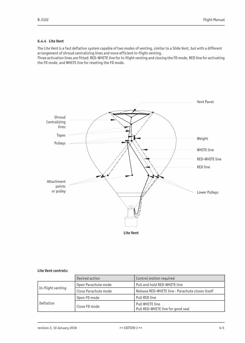
B.3102 Flight Manual
revision 2, 10 January 2018 >> EDITION 3 << 6-5
6.4.4 Lite Vent
The Lite Vent is a fast deflation system capable of two modes of venting, similar to a Slide Vent, but with a differentarrangement of shroud centralizing lines and more efficient in-flight venting.Three activation lines are fitted: RED-WHITE line for in-flight venting and closing the FD mode, RED line for activatingthe FD mode, and WHITE line for reseting the FD mode.
ShroudCentralizing
lines
Tapes
Attachmentpoints
or pulley
Weight
WHITE line
RED-WHITE line
Lower Pulleys
RED line
Lite Vent
Vent Panel
Pulleys
Lite Vent controls:
Desired action Control motion required
In-flight ventingOpen Parachute mode Pull and hold RED-WHITE line
Close Parachute mode Release RED-WHITE line - Parachute closes itself
DeflationOpen FD mode Pull RED line
Close FD modePull WHITE linePull RED-WHITE line for good seal
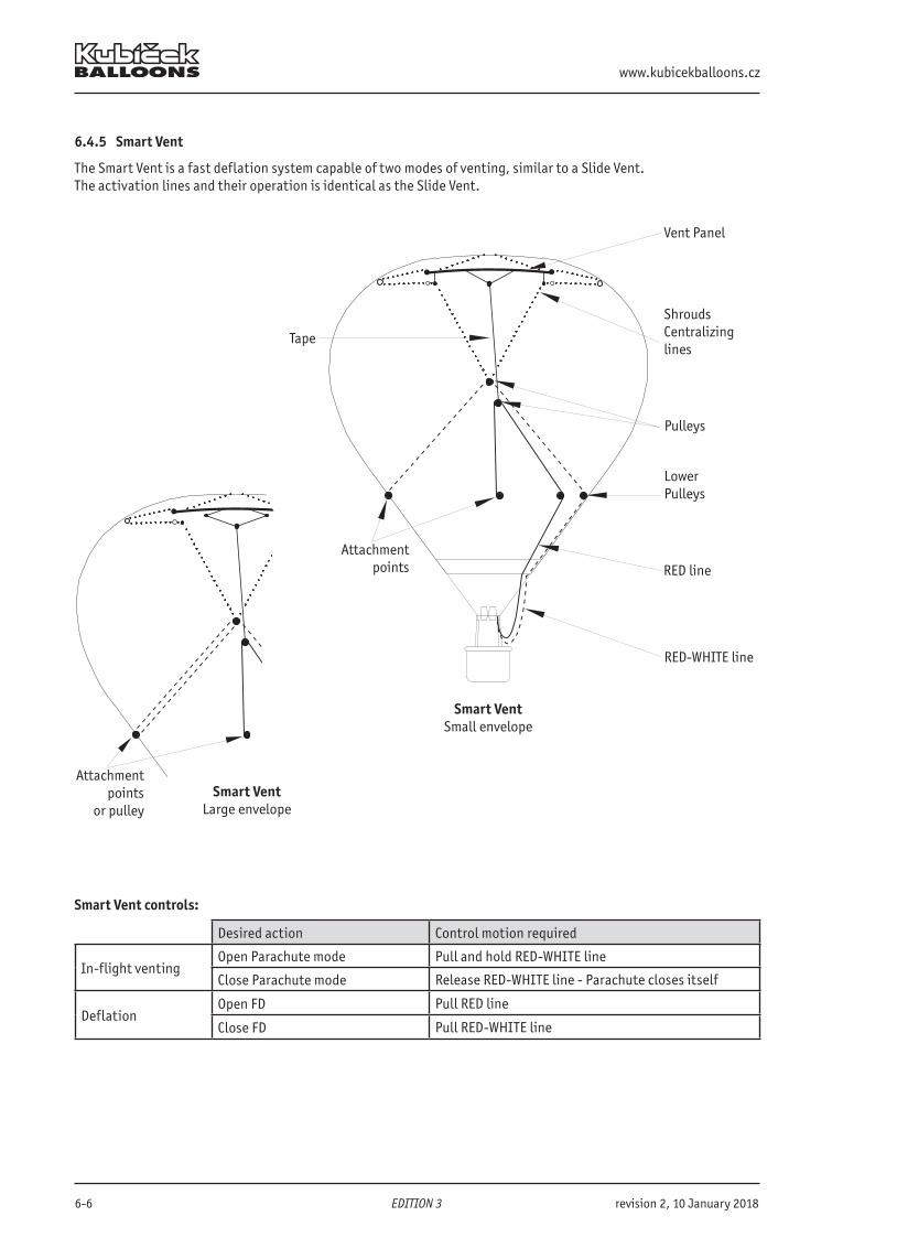
www.kubicekballoons.cz
6-6 EDITION 3 revision 2, 10 January 2018
6.4.5 Smart Vent
The Smart Vent is a fast deflation system capable of two modes of venting, similar to a Slide Vent.The activation lines and their operation is identical as the Slide Vent.
Attachmentpoints
or pulleySmart Vent
Large envelope
Vent Panel
ShroudsCentralizinglines
Pulleys
LowerPulleys
RED line
RED-WHITE line
Tape
Smart VentSmall envelope
Attachmentpoints
Smart Vent controls:
Desired action Control motion required
In-flight ventingOpen Parachute mode Pull and hold RED-WHITE line
Close Parachute mode Release RED-WHITE line - Parachute closes itself
DeflationOpen FD Pull RED line
Close FD Pull RED-WHITE line
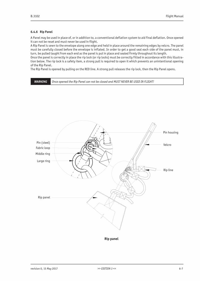
B.3102 Flight Manual
revision 0, 15 May 2017 >> EDITION 3 << 6-7
6.4.6 Rip Panel
A Panel may be used in place of, or in addition to, a conventional deflation system to aid final deflation. Once opened it can not be reset and must never be used in flight.A Rip Panel is sewn to the envelope along one edge and held in place around the remaining edges by velcro. The panelmust be carefully closed before the envelope is inflated. In order to get a good seal each side of the panel must, in turn, be pulled taught from each end as the panel is put in place and sealed firmly throughout its length.Once the panel is correctly in place the rip lock (or rip locks) must be correctly fitted in accordance with this illustra-tion below. The rip lock is a safety item, a strong pull is required to open it which prevents an unintentional opening of the Rip Panel.The Rip Panel is opened by pulling on the RED line. A strong pull releases the rip lock, then the Rip Panel opens.
WARNING Once opened the Rip Panel can not be closed and MUST NEVER BE USED IN FLIGHT!
Pin (steel)
Fabric loop
Middle ring
Large ring
Rip panel
Rip panel
Pin housing
Velcro
Rip line
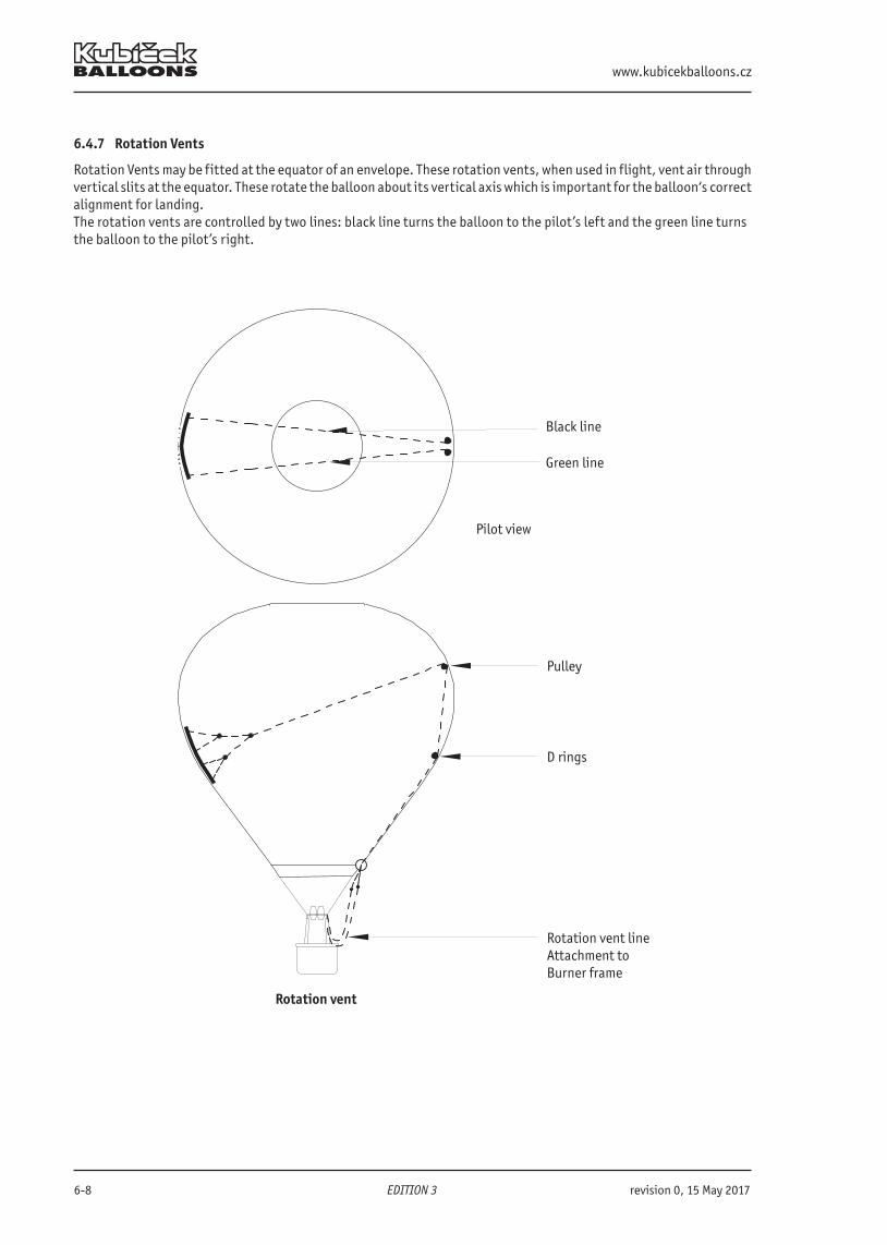
www.kubicekballoons.cz
6-8 EDITION 3 revision 0, 15 May 2017
6.4.7 Rotation Vents
Rotation Vents may be fitted at the equator of an envelope. These rotation vents, when used in flight, vent air throughvertical slits at the equator. These rotate the balloon about its vertical axis which is important for the balloon‘s correctalignment for landing.The rotation vents are controlled by two lines: black line turns the balloon to the pilot’s left and the green line turnsthe balloon to the pilot’s right.
Black line
Green line
Pilot view
Pulley
D rings
Rotation vent lineAttachment to Burner frame
Rotation vent
B.3102 Flight Manual
revision 0, 15 May 2017 >> EDITION 3 << 6-9
6.4.8 Temperature Streamer
A Temperature Streamer is a fabric flag of a contrasting color attached inside the envelope on its top via a melting link. If the envelope is overheated the solder in the melting link melts and the Temperature Streamer falls out of the envelope warning the pilot. The melting ling is designed to detach at 124°C (255°F).
CAUTIONThe fall of the Temperature Streamer need not indicate an immediate danger. The balloon remains cont-rollable but intense maneuvers must be avoided. Heat carefully using only short bursts. Note the altitude in which the Temperature Streamer fell and keep lower for the rest of the flight.
Once the Temperature Streamer has fallen, the melting link must be changed for a new one and envelope inspection is required in certain cases. See KB Maintenance Manual for details.
6.4.9 Tempilabel
A Tempilabel is a small strip sewn inside the envelope with several temperature-sensitive areas changing color per-manently according to the temperature reached. This provides a permanent record of the maximum temperature thatthe envelope has reached.After overheating of the envelope a new tempilabel is sewn alongside the old one which must remain.
6.5 BurnerThe burner is the heat source of the balloon and an efficient means for controlling the vertical profile of the flight. Itconsists of one or more burner units and a burner frame. Within the burner, liquid gas is vaporized and burnt to heat the air within the envelope. The gas is ignited by a pilot light that runs all the time that the balloon is inflated. Both the main burner and whisper burner have an “off” or “on” mode. The amount of heat is controlled by duration of the heating and number of burner units engaged. All burners are controlled by means of the valves placed on the under-side of the burner on the manifold block. The heat of the burner is greatly influenced by the fuel pressure that is affected by the ambient temperature. In lowertemperatures pressurization of the fuel cylinders is recommended.
CAUTIONBurner malfunction due to oxygen insufficiency in the ambient air may appear in altitudes above 6 000m (20 000 ft) AMSL.
6.5.1 Main Burner
The high output Main Burner is fed with liquid propane which passes through a vaporizing coil prior to combustion. Fuel flow is controlled by an on/off valve called the Main Blast Valve.
6.5.2 Whisper Burner
A whisper burner (AKA Liquid Fire or Cow burner) is fitted to each burner unit. The Whisper Burner feeds liquid fuel di-rectly to a multi hole jet without passing through the vaporizing coil. This provides a quieter but less powerful flame. It is intended for use when reduction of burner noise is desired.
6.5.3 Pilot Flame
Burner ignition is provided by a pilot flame. A pilot flame is fueled either by liquid propane taken from the burner block and vaporized in the vaporizer or from vapor taken by a separate hose from the fuel cylinder. Each pilot flame has its own piezo igniter which is covered by the handle of the pilot flame lever, when it is in the off position.To run the pilot flame, open the valve and ignite the vapor using the piezo igniter. To turn the pilot light off move thepilot flame lever to the closed position.The piezo igniter is activated by pressing on the piezo button. Pressing the button causes a spark between the upper point of the igniter and the pilot light cup and ignites the pilot flame.
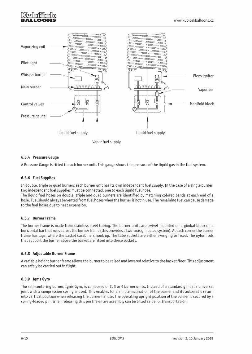
www.kubicekballoons.cz
6-10 EDITION 3 revision 2, 10 January 2018
Vaporizing coil
Pilot light
Main burner
Pressure gauge
Whisper burner
Control valves
Liquid fuel supplyLiquid fuel supply
Vapor fuel supply
Piezo igniter
Vaporizer
Manifold block
6.5.4 Pressure Gauge
A Pressure Gauge is fitted to each burner unit. This gauge shows the pressure of the liquid gas in the fuel system.
6.5.6 Fuel Supplies
In double, triple or quad burners each burner unit has its own independent fuel supply. In the case of a single burnertwo independent fuel supplies must be connected, one to each liquid fuel hose.The liquid fuel hoses on double, triple and quad burners are identified by matching colored bands at each end of a hose. Fuel should always be vented from fuel hoses when the burner is not in use. The remaining fuel can cause damage to the fuel hoses due to heat expansion.
6.5.7 Burner Frame
The burner frame is made from stainless steel tubing. The burner units are swivel-mounted on a gimbal block on a horizontal bar that runs across the burner frame (this provides a two-axis gimbaled system). At each corner the burnerframe has lugs, where the basket carabiners hook up. The tube sockets are either swinging or fixed. The nylon rods that support the burner above the basket are fitted into these sockets.
6.5.8 Adjustable Burner Frame
A variable height burner frame allows the burner to be raised and lowered relative to the basket floor. This adjustment can safely be carried out in flight.
6.5.9 Ignis Gyro
The self-centering burner, Ignis Gyro, is composed of 2, 3 or 4 burner units. Instead of a standard gimbal a universal joint with a compression spring is used. This enables for a simple inclination of the burner and its automatic return into vertical position when releasing the burner handle. The operating upright position of the burner is secured by a spring-loaded pin. When releasing this pin the entire assembly can be tilted aside for transportation.
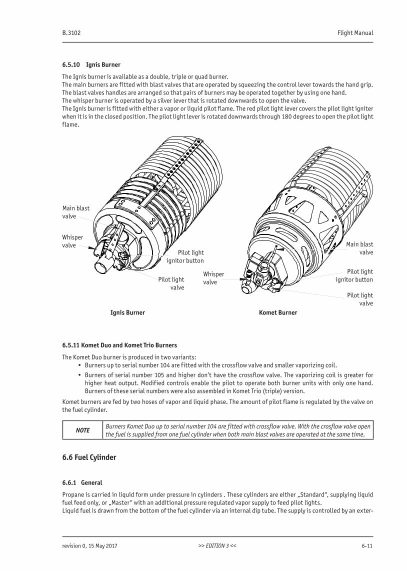
B.3102 Flight Manual
revision 0, 15 May 2017 >> EDITION 3 << 6-11
6.5.10 Ignis Burner
The Ignis burner is available as a double, triple or quad burner.The main burners are fitted with blast valves that are operated by squeezing the control lever towards the hand grip. The blast valves handles are arranged so that pairs of burners may be operated together by using one hand. The whisper burner is operated by a silver lever that is rotated downwards to open the valve.The Ignis burner is fitted with either a vapor or liquid pilot flame. The red pilot light lever covers the pilot light igniter when it is in the closed position. The pilot light lever is rotated downwards through 180 degrees to open the pilot light flame.
Pilot lightignitor button
Pilot lightvalve
Whisper valve
Main blast valve
Main blast valve
Whisper valve
Pilot lightignitor button
Pilot lightvalve
Ignis Burner Komet Burner
6.5.11 Komet Duo and Komet Trio Burners
The Komet Duo burner is produced in two variants:• Burners up to serial number 104 are fitted with the crossflow valve and smaller vaporizing coil.
• Burners of serial number 105 and higher don’t have the crossflow valve. The vaporizing coil is greater for higher heat output. Modified controls enable the pilot to operate both burner units with only one hand.Burners of these serial numbers were also assembled in Komet Trio (triple) version.
Komet burners are fed by two hoses of vapor and liquid phase. The amount of pilot flame is regulated by the valve on the fuel cylinder.
NOTE Burners Komet Duo up to serial number 104 are fitted with crossflow valve. With the crosflow valve open the fuel is supplied from one fuel cylinder when both main blast valves are operated at the same time.
6.6 Fuel Cylinder
6.6.1 General
Propane is carried in liquid form under pressure in cylinders . These cylinders are either „Standard“, supplying liquid fuel feed only, or „Master“ with an additional pressure regulated vapor supply to feed pilot lights.Liquid fuel is drawn from the bottom of the fuel cylinder via an internal dip tube. The supply is controlled by an exter-
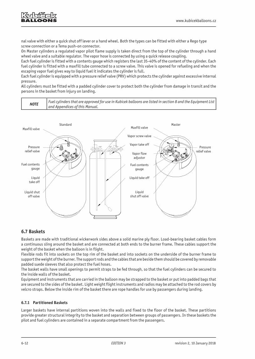
www.kubicekballoons.cz
6-12 EDITION 3 revision 2, 10 January 2018
nal valve with either a quick shut off lever or a hand wheel. Both the types can be fitted with either a Rego typescrew connection or a Tema push-on connector. On Master cylinders a regulated vapor pilot flame supply is taken direct from the top of the cylinder through a hand wheel valve and a suitable regulator. The vapor hose is connected by using a quick release coupling.Each fuel cylinder is fitted with a contents gauge which registers the last 35-40% of the content of the cylinder. Eachfuel cylinder is fitted with a maxfill tube connected to a screw valve. This valve is opened for refueling and when the escaping vapor fuel gives way to liquid fuel it indicates the cylinder is full.Each fuel cylinder is equipped with a pressure relief valve (PRV) which protects the cylinder against excessive internal pressure.All cylinders must be fitted with a padded cylinder cover to protect both the cylinder from damage in transit and the persons in the basket from injury on landing.
NOTE Fuel cylinders that are approved for use in Kubicek balloons are listed in section 8 and the Equipment List and Appendices of this Manual.
Maxfill valve
Vapor screw valve
Vapor take off
Fuel contentsgauge
Liquid take off
Liquidshut off valve
Vapor flowadjustor
Maxfill valve
Pressurerelief valve
Fuel contentsgauge
Liquidtake off
Liquid shut off valve
Standard Master
Pressure relief valve
6.7 BasketsBaskets are made with traditional wickerwork sides above a solid marine ply floor. Load-bearing basket cables form a continuous sling around the basket and are connected at both ends to the burner frame. These cables support the weight of the basket when the balloon is in flight.Flexible rods fit into sockets on the top rim of the basket and into sockets on the underside of the burner frame to support the weight of the burner. The support rods and the cables that are beside them should be covered by removablepadded suede sleeves that also protect the fuel hoses.The basket walls have small openings to permit straps to be fed through, so that the fuel cylinders can be secured to the inside walls of the basket.Equipment and instruments that are carried in the balloon may be strapped to the basket or put into padded bags that are secured to the sides of the basket. Light weight flight instruments and radios may be attached to the rod covers by velcro straps. Below the inside rim of the basket there are rope handles for use by passengers during landing.
6.7.1 Partitioned Baskets
Larger baskets have internal partitions woven into the walls and fixed to the floor of the basket. These partitions provide greater structural integrity to the basket and separation between groups of passengers. In these baskets the pilot and fuel cylinders are contained in a separate compartment from the passengers.
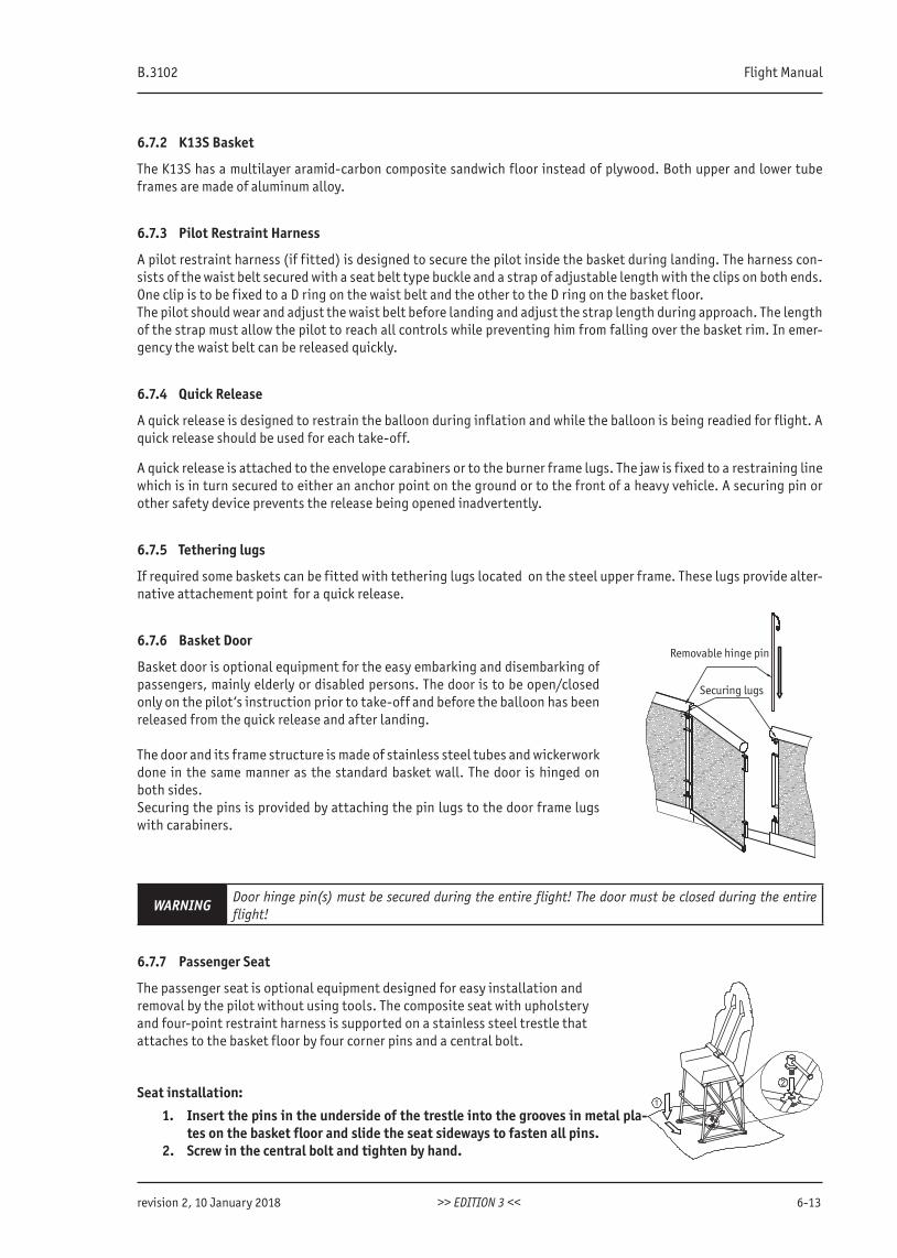
B.3102 Flight Manual
revision 2, 10 January 2018 >> EDITION 3 << 6-13
6.7.2 K13S Basket
The K13S has a multilayer aramid-carbon composite sandwich floor instead of plywood. Both upper and lower tube frames are made of aluminum alloy.
6.7.3 Pilot Restraint Harness
A pilot restraint harness (if fitted) is designed to secure the pilot inside the basket during landing. The harness con-sists of the waist belt secured with a seat belt type buckle and a strap of adjustable length with the clips on both ends. One clip is to be fixed to a D ring on the waist belt and the other to the D ring on the basket floor.The pilot should wear and adjust the waist belt before landing and adjust the strap length during approach. The lengthof the strap must allow the pilot to reach all controls while preventing him from falling over the basket rim. In emer-gency the waist belt can be released quickly.
6.7.4 Quick Release
A quick release is designed to restrain the balloon during inflation and while the balloon is being readied for flight. Aquick release should be used for each take-off.
A quick release is attached to the envelope carabiners or to the burner frame lugs. The jaw is fixed to a restraining line which is in turn secured to either an anchor point on the ground or to the front of a heavy vehicle. A securing pin or other safety device prevents the release being opened inadvertently.
6.7.5 Tethering lugs
If required some baskets can be fitted with tethering lugs located on the steel upper frame. These lugs provide alter-native attachement point for a quick release.
6.7.6 Basket Door
Basket door is optional equipment for the easy embarking and disembarking of passengers, mainly elderly or disabled persons. The door is to be open/closed only on the pilot‘s instruction prior to take-off and before the balloon has been released from the quick release and after landing.
The door and its frame structure is made of stainless steel tubes and wickerwork done in the same manner as the standard basket wall. The door is hinged on both sides. Securing the pins is provided by attaching the pin lugs to the door frame lugs with carabiners.
WARNING Door hinge pin(s) must be secured during the entire flight! The door must be closed during the entire flight!
6.7.7 Passenger Seat
The passenger seat is optional equipment designed for easy installation andremoval by the pilot without using tools. The composite seat with upholsteryand four-point restraint harness is supported on a stainless steel trestle thatattaches to the basket floor by four corner pins and a central bolt.
Seat installation:
1. Insert the pins in the underside of the trestle into the grooves in metal pla-tes on the basket floor and slide the seat sideways to fasten all pins.
2. Screw in the central bolt and tighten by hand.
Removable hinge pin
Securing lugs
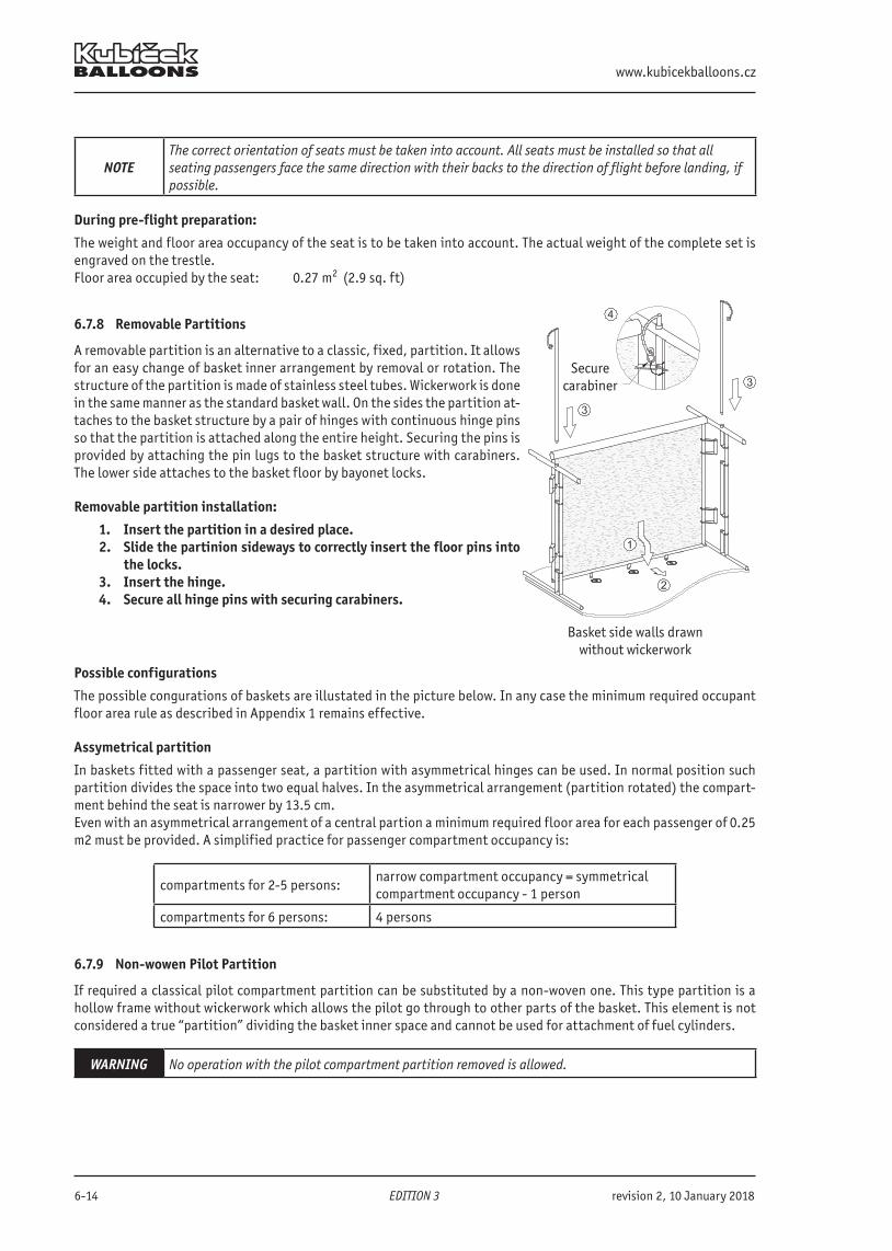
www.kubicekballoons.cz
6-14 EDITION 3 revision 2, 10 January 2018
NOTEThe correct orientation of seats must be taken into account. All seats must be installed so that allseating passengers face the same direction with their backs to the direction of flight before landing, ifpossible.
During pre-flight preparation:
The weight and floor area occupancy of the seat is to be taken into account. The actual weight of the complete set is engraved on the trestle.Floor area occupied by the seat: 0.27 m2 (2.9 sq. ft)
6.7.8 Removable Partitions
A removable partition is an alternative to a classic, fixed, partition. It allowsfor an easy change of basket inner arrangement by removal or rotation. The structure of the partition is made of stainless steel tubes. Wickerwork is done in the same manner as the standard basket wall. On the sides the partition at-taches to the basket structure by a pair of hinges with continuous hinge pins so that the partition is attached along the entire height. Securing the pins is provided by attaching the pin lugs to the basket structure with carabiners. The lower side attaches to the basket floor by bayonet locks.
Removable partition installation:
1. Insert the partition in a desired place.2. Slide the partinion sideways to correctly insert the floor pins into
the locks.3. Insert the hinge.4. Secure all hinge pins with securing carabiners.
Possible configurations
The possible congurations of baskets are illustated in the picture below. In any case the minimum required occupant floor area rule as described in Appendix 1 remains effective.
Assymetrical partition
In baskets fitted with a passenger seat, a partition with asymmetrical hinges can be used. In normal position such partition divides the space into two equal halves. In the asymmetrical arrangement (partition rotated) the compart-ment behind the seat is narrower by 13.5 cm.Even with an asymmetrical arrangement of a central partion a minimum required floor area for each passenger of 0.25m2 must be provided. A simplified practice for passenger compartment occupancy is:
compartments for 2-5 persons:narrow compartment occupancy = symmetrical compartment occupancy - 1 person
compartments for 6 persons: 4 persons
6.7.9 Non-wowen Pilot Partition
If required a classical pilot compartment partition can be substituted by a non-woven one. This type partition is a hollow frame without wickerwork which allows the pilot go through to other parts of the basket. This element is not considered a true “partition” dividing the basket inner space and cannot be used for attachment of fuel cylinders.
WARNING No operation with the pilot compartment partition removed is allowed.
Securecarabiner
Basket side walls drawn without wickerwork
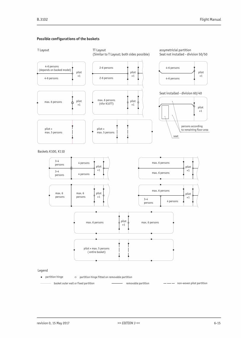
B.3102 Flight Manual
revision 0, 15 May 2017 >> EDITION 3 << 6-15
Possible configurations of the baskets
Baskets K100, K110
T Layout TT Layout(Similar to T Layout; both sides possible)
assymetricial partition Seat not installed - division 50/50
Seat installed - division 60/40
4-6 persons(depends on basked model)
4-6 persons
pilot+1
2-6 persons
2-6 persons
pilot+1
4-6 persons
4-6 persons
pilot+1
max. 6 persons pilot+1
max. 6 persons (4for K32TT)
pilot+1
pilot+1
pilot + max. 5 persons
pilot + max. 5 persons
3-4persons
3-4persons
4 persons
4 persons
pilot+1
max. 6persons
max. 6persons
pilot+1
max. 6 persons
max. 6 persons
max. 6 persons
pilot+1
pilot+1
3-4persons 4 persons
max. 6 persons max. 6 persons
pilot + max. 5 persons( entire basket)
pilot+1
Legend
partition hinge
basket outer wall or fixed partition
partition hinge fitted on removable partition
removable partition non-woven pilot partition
persons accordingto remaining floor area
seat
www.kubicekballoons.cz
6-16 EDITION 3 revision 0, 15 May 2017
6.8 InstrumentsThe instruments used in a balloon are an altimeter (for height measurement), a variometer (to show the balloon’s rate of climb or descent), and an envelope temperature gauge (to show the envelope’s actual internal temperature or overheating).
6.9 Other Equipment
6.9.1 Drop Line
The drop line may be used by ground crew to manoeuvre the balloon in light wind conditions. When not in use the drop line is rolled up in a fabric bag, and secured inside the basket.
6.9.2 Fire Extinguisher and Fire Blanket
These items are contained within padded bags in the basket and must always be carried in the basket for use in an emergency.
B.3102 Flight Manual
revision 2, 10 January 2018 >> EDITION 3 << 7-1
SECTION 7 - BALLOON HANDLING, CARE AND MAINTENANCE
7.1 IntroductionThis section contains the manufacturer s recommended procedures for ground handling and servicing of the balloon.It also identifies certain inspection and maintenance requirements which must be followed, if the balloon is to retainthat new-balloon performance and dependability.
7.2 Inspection PeriodsIn order to maintain continued airworthiness the following inspections must be made at the appropriate times. Any inspection required by the country in which the balloon is registered and operated must also be completed. Details of inspections, procedures and the licensing requirements of those people who may carry out inspections is contained in the Maintenance Manual for a specific balloon.A summary of inspections prescribed by the manufacturer is:
Inspection Type Operating Period Inspect
Annual inspection 100 flight hours or 12 calendar mon-ths, whichever is the sooner
Balloon envelope, basket, burner, fuel cylinders, instruments, equip-ment and accessories
Ten yearly inspection Ten years* Fuel cylinders (see the Maintenance Manual)
* Determination of inspection dates is based on the date of production, or date of inspection, if any marked on each cylinder.
7.3 Balloon Maintenance, Repairs and AlterationsAll balloon maintenance and repairs must be carried out in accordance with to the Kubicek Balloons Maintenance Manual. If in doubt, contact KB (see the last page of this Manual).
7.4 Ground Handling and Road TransportAfter a flight is completed, pack the envelope and transport it in the original envelope bag. The envelope should be kept dry during transport.Always Vent the burner hoses. Check that the fuel cylinder valves are closed and burner hoses are disconnect from thefuel cylinders.If the basket is to be winched lengthways onto a vehicle or trailer only approved basket towing loop should be used.The winch cable must not be attached to the rope handles or any other part of the basket.Burners with liquid pilot flames should be transported and stored with the coils uppermost. This will prevent any oil residue in the vaporizer units running into and blocking the pilot flame jets.When in transit secure the various components of the balloon to eliminate the possibility of damage.Fuel cylinders should be transported in a vertical position with the valves uppermost and in accordance with the pro-cedures recommended by your national regulatory authority for the transport of liquefied gas tanks.
WARNING Never store or transport a burner with any portion of gas in the fuel hoses.
7.5 Cleaning and Care
7.5.1 Envelope
Soiled areas should be cleaned by using a damp cloth. Mild detergents diluted with water may also be used. Before packing the envelope should be thoroughly dried.
www.kubicekballoons.cz
7-2 EDITION 3 revision 2, 10 January 2018
7.5.2 Basket
The basket requires periodic cleaning. The cane and floor should be cleaned with flowing water and a brush, or pre-ssure washed (protect the upper suede rim from getting wet. The basket should be allowed to dry completely before being stored.Preserve the cane from becoming too dry because it will become brittle. Clean and protect the leather on the basket bottom and suede on the top rim using products for leather and suede care. If there is a suede cover on the upper rim,simply restore it by brushing with a suede shoe-brush.
7.5.3 Passenger Seat
When dirty, the seat upholstery should be cleaned with a car upholstery cleaning agent. Do not soak it with water. For other parts use mild soapy solution. Allow all parts to dry well before storing.Store the seat in a clean airy dry place.
7.5.4 Burner
After each flight clean carbon deposits from the burner. Check that the movable parts on the frame, frame suspensionand hose fittings are free of dirt and mud. Clean and lubricate with silicone oil as required.Check periodically that the burner valves move smoothly. Lubricate the valves as described in the Kubicek Balloons Maintenance Manual, if they are becoming stiff.
7.5.5 Fuel Cylinders
Check that the control valves move smoothly and that the pressure regulator is correctly adjusted . Consult your KB approved repair station, if there is any suspicion that they are not working properly or if there is damage to the body of the cylinder.Lubricate ,O’ ring seals, when required. Keep the areas around the valves and end connectors clean.
7.5.6 Instruments
Follow the respective manual for the instrument.
7.6 StorageThe balloon must be stored in a clean dry airy place with the envelope in its bag, if possible on a pallet.The envelope should not be stored damp or wet for more than a few days because residual moisture can result in fabric deterioration due to mold or mildew. A wet envelope should be gently dried by keeping it cold inflated with a fan tur-ning it over as necessary. hot inflating a wet envelope may damage the fabric. Do not expose the envelope to direct sunshine or direct heat when drying.Store the basket on a pallet so that it is clear of the ground. Water soaking into the wicker and hide of the basket will cause it to deteriorate, so always remove mud from the basket and make sure that it stays dry.Cylinders should be stored in vertical position,with their valves uppermost in a well ventilated area with no source of ignition or excessive heat.Burner hoses and T-manifolds must be vented of all fuel as trapped fuel will expand and may cause damage to the hose. While packing the burner the hoses should be rolled on the frame so that there will be no sharp bend on the hose. Special caution should be taken not to kink the hose next to the output fitting. Fuel hoses may never be bent sharply, the smallest bend radius allowed is 90 mm (3 1/2“). A template is provided in Appendix 5.
CAUTIONFuel cylinders that have been pressurized with nitrogen, but not used at once, should be vented at least for 5 minutes.
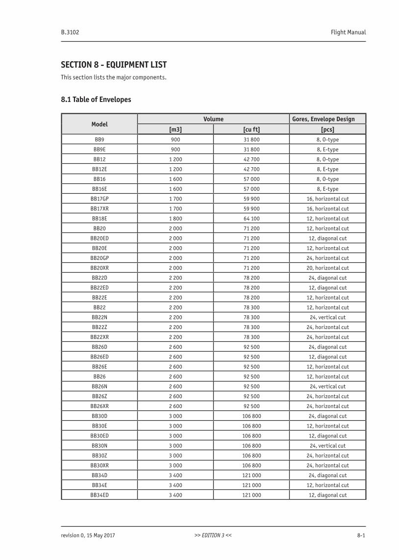
B.3102 Flight Manual
revision 0, 15 May 2017 >> EDITION 3 << 8-1
SECTION 8 - EQUIPMENT LIST This section lists the major components.
8.1 Table of Envelopes
ModelVolume Gores, Envelope Design
[m3] [cu ft] [pcs]BB9 900 31 800 8, O-type
BB9E 900 31 800 8, E-type
BB12 1 200 42 700 8, O-type
BB12E 1 200 42 700 8, E-type
BB16 1 600 57 000 8, O-type
BB16E 1 600 57 000 8, E-type
BB17GP 1 700 59 900 16, horizontal cut
BB17XR 1 700 59 900 16, horizontal cut
BB18E 1 800 64 100 12, horizontal cut
BB20 2 000 71 200 12, horizontal cut
BB20ED 2 000 71 200 12, diagonal cut
BB20E 2 000 71 200 12, horizontal cut
BB20GP 2 000 71 200 24, horizontal cut
BB20XR 2 000 71 200 20, horizontal cut
BB22D 2 200 78 200 24, diagonal cut
BB22ED 2 200 78 200 12, diagonal cut
BB22E 2 200 78 200 12, horizontal cut
BB22 2 200 78 300 12, horizontal cut
BB22N 2 200 78 300 24, vertical cut
BB22Z 2 200 78 300 24, horizontal cut
BB22XR 2 200 78 300 24, horizontal cut
BB26D 2 600 92 500 24, diagonal cut
BB26ED 2 600 92 500 12, diagonal cut
BB26E 2 600 92 500 12, horizontal cut
BB26 2 600 92 500 12, horizontal cut
BB26N 2 600 92 500 24, vertical cut
BB26Z 2 600 92 500 24, horizontal cut
BB26XR 2 600 92 500 24, horizontal cut
BB30D 3 000 106 800 24, diagonal cut
BB30E 3 000 106 800 12, horizontal cut
BB30ED 3 000 106 800 12, diagonal cut
BB30N 3 000 106 800 24, vertical cut
BB30Z 3 000 106 800 24, horizontal cut
BB30XR 3 000 106 800 24, horizontal cut
BB34D 3 400 121 000 24, diagonal cut
BB34E 3 400 121 000 12, horizontal cut
BB34ED 3 400 121 000 12, diagonal cut
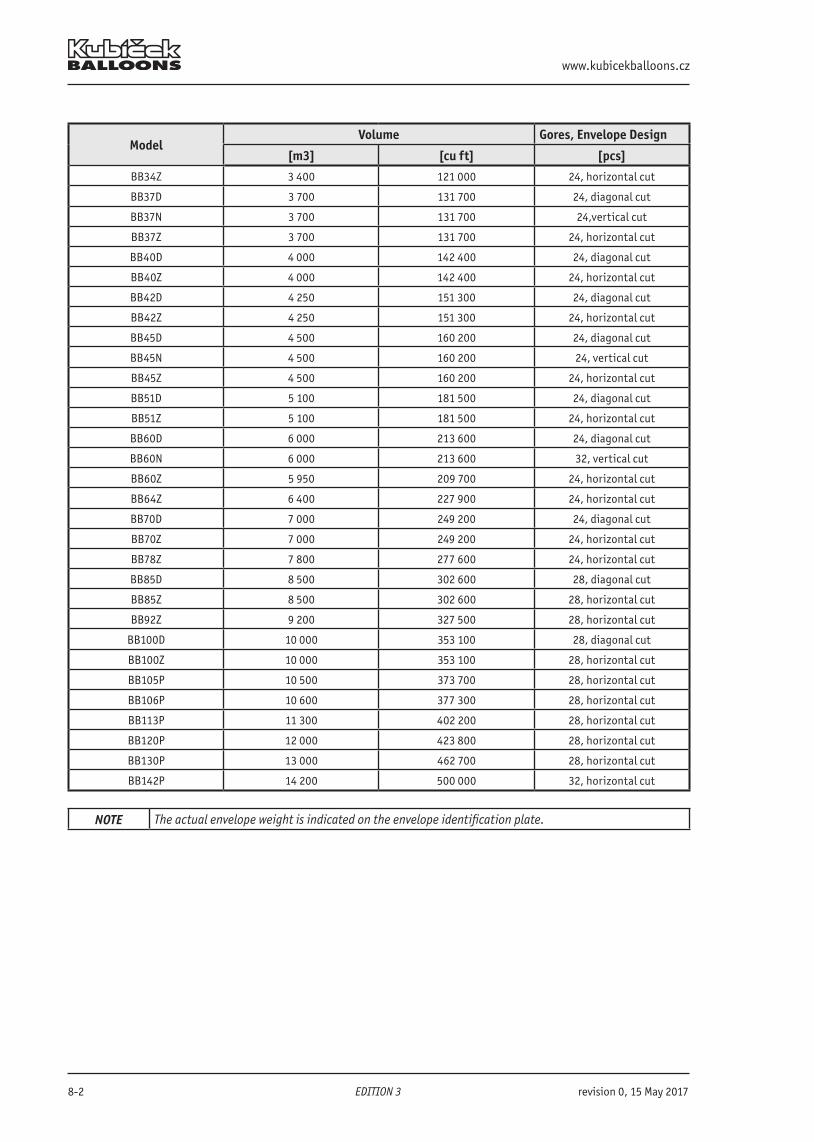
www.kubicekballoons.cz
8-2 EDITION 3 revision 0, 15 May 2017
ModelVolume Gores, Envelope Design
[m3] [cu ft] [pcs]
BB34Z 3 400 121 000 24, horizontal cut
BB37D 3 700 131 700 24, diagonal cut
BB37N 3 700 131 700 24,vertical cut
BB37Z 3 700 131 700 24, horizontal cut
BB40D 4 000 142 400 24, diagonal cut
BB40Z 4 000 142 400 24, horizontal cut
BB42D 4 250 151 300 24, diagonal cut
BB42Z 4 250 151 300 24, horizontal cut
BB45D 4 500 160 200 24, diagonal cut
BB45N 4 500 160 200 24, vertical cut
BB45Z 4 500 160 200 24, horizontal cut
BB51D 5 100 181 500 24, diagonal cut
BB51Z 5 100 181 500 24, horizontal cut
BB60D 6 000 213 600 24, diagonal cut
BB60N 6 000 213 600 32, vertical cut
BB60Z 5 950 209 700 24, horizontal cut
BB64Z 6 400 227 900 24, horizontal cut
BB70D 7 000 249 200 24, diagonal cut
BB70Z 7 000 249 200 24, horizontal cut
BB78Z 7 800 277 600 24, horizontal cut
BB85D 8 500 302 600 28, diagonal cut
BB85Z 8 500 302 600 28, horizontal cut
BB92Z 9 200 327 500 28, horizontal cut
BB100D 10 000 353 100 28, diagonal cut
BB100Z 10 000 353 100 28, horizontal cut
BB105P 10 500 373 700 28, horizontal cut
BB106P 10 600 377 300 28, horizontal cut
BB113P 11 300 402 200 28, horizontal cut
BB120P 12 000 423 800 28, horizontal cut
BB130P 13 000 462 700 28, horizontal cut
BB142P 14 200 500 000 32, horizontal cut
NOTE The actual envelope weight is indicated on the envelope identification plate.
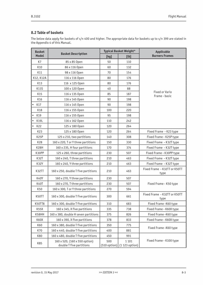
B.3102 Flight Manual
revision 0, 15 May 2017 >> EDITION 3 << 8-3
8.2 Table of basketsThe below data apply for baskets of s/n 400 and higher. The appropriate data for baskets up to s/n 399 are stated in the Appendix 4 of this Manual.
Basket Model Basket Description
Typical Basket Weight* ApplicableBurners Frames[kg] [lb]
K7 85 x 85 Open 50 110
Fixed or VarioFrame - basic
K10 86 x 116 Open 60 132
K11 98 x 116 Open 70 154
K12, K12A 116 x 116 Open 80 176
K13 116 x 125 Open 80 176
K13S 100 x 120 Open 40 88
K15 116 x 135 Open 85 187
K16 116 x 145 Open 90 198
• K17 116 x 145 Open 90 198
K18 116 x 155 Open 100 220
• K19 116 x 155 Open 95 198
• K19L 116 x 162 Open 110 242
• K22 125 x 180 Open 120 264
K23 125 x 180 Open 120 264 Fixed Frame - K23 type
K25P 125 x 210, two partitions 140 308 Fixed Frame - K25P type
K28 160 x 220, T or Y three partitions 150 330 Fixed Frame - K32T type
K28H 160 x 235, H four partitions 170 374 Fixed Frame - K32T type
K30PP 125 x 260, three partitions 230 507 Fixed Frame - K30PP type
K32T 160 x 240, T three partitions 210 463 Fixed Frame - K32T type
K32Y 160 x 240, Y three partitions 210 463 Fixed Frame - K32T type
K32TT 160 x 250, double T five partitions 210 463Fixed Frame - K32TT or K50TT
type
K40Y 160 x 270, Y three partitions 230 507
Fixed Frame - K50 typeK40T 160 x 270, T three partitions 230 507
K50 160 x 300, T or Y three partitions 270 594
K50TT 160 x 300, double T five partitions 300 661Fixed Frame - K32TT or K50TT
type
K50TT8 160 x 300, double T five partitions 310 683 Fixed Frame -K60 type
K55X 160 x 345, X five partitions 335 738 Fixed Frame - K60X type
K58HH 160 x 380, double H seven partitions 375 826 Fixed Frame -K60 type
K60X 160 x 390, X five partitions 378 833 Fixed Frame - K60X type
K60 160 x 380, double T five partitions 350 775Fixed Frame -K60 type
K70 160 x 440, double T five partitions 400 881
K80 160 x 480, double T five partitions 450 991Fixed Frame - K100 type
K85160 x 520, (160 x 550 option)
double T five partitions500
(510 option)1 101
(1 123 option)
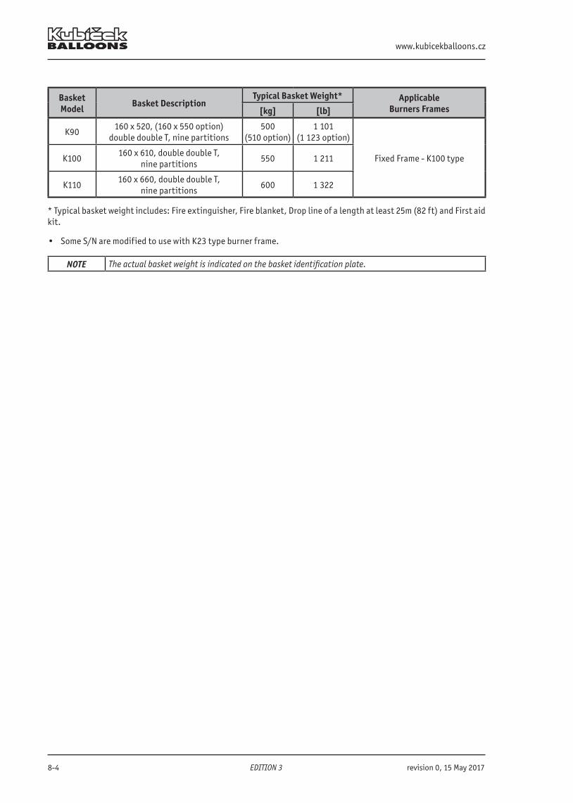
www.kubicekballoons.cz
8-4 EDITION 3 revision 0, 15 May 2017
Basket Model Basket Description
Typical Basket Weight* ApplicableBurners Frames[kg] [lb]
K90160 x 520, (160 x 550 option)
double double T, nine partitions500
(510 option)1 101
(1 123 option)
Fixed Frame - K100 typeK100160 x 610, double double T,
nine partitions550 1 211
K110160 x 660, double double T,
nine partitions600 1 322
* Typical basket weight includes: Fire extinguisher, Fire blanket, Drop line of a length at least 25m (82 ft) and First aid kit.
• Some S/N are modified to use with K23 type burner frame.
NOTE The actual basket weight is indicated on the basket identification plate.
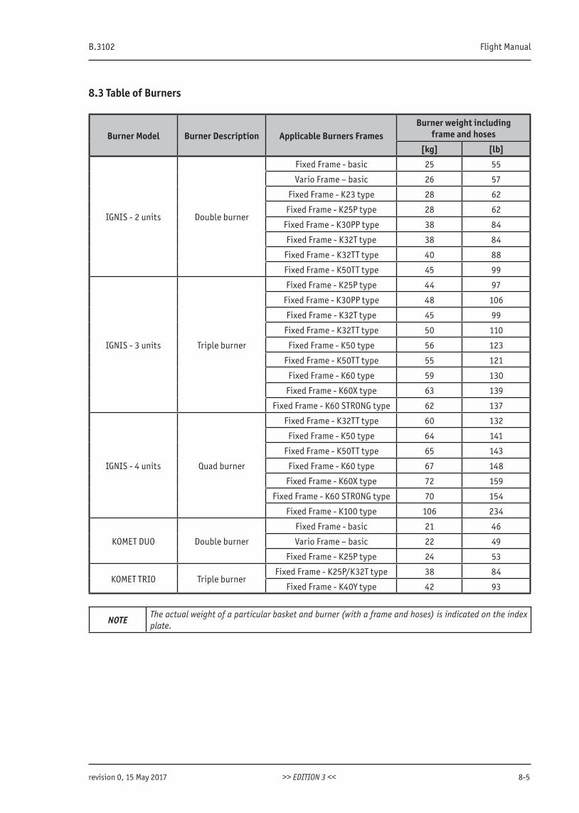
B.3102 Flight Manual
revision 0, 15 May 2017 >> EDITION 3 << 8-5
8.3 Table of Burners
Burner Model Burner Description Applicable Burners FramesBurner weight including
frame and hoses
[kg] [lb]
IGNIS - 2 units Double burner
Fixed Frame - basic 25 55
Vario Frame – basic 26 57
Fixed Frame - K23 type 28 62
Fixed Frame - K25P type 28 62
Fixed Frame - K30PP type 38 84
Fixed Frame - K32T type 38 84
Fixed Frame - K32TT type 40 88
Fixed Frame - K50TT type 45 99
IGNIS - 3 units Triple burner
Fixed Frame - K25P type 44 97
Fixed Frame - K30PP type 48 106
Fixed Frame - K32T type 45 99
Fixed Frame - K32TT type 50 110
Fixed Frame - K50 type 56 123
Fixed Frame - K50TT type 55 121
Fixed Frame - K60 type 59 130
Fixed Frame - K60X type 63 139
Fixed Frame - K60 STRONG type 62 137
IGNIS - 4 units Quad burner
Fixed Frame - K32TT type 60 132
Fixed Frame - K50 type 64 141
Fixed Frame - K50TT type 65 143
Fixed Frame - K60 type 67 148
Fixed Frame - K60X type 72 159
Fixed Frame - K60 STRONG type 70 154
Fixed Frame - K100 type 106 234
KOMET DUO Double burner
Fixed Frame - basic 21 46
Vario Frame – basic 22 49
Fixed Frame - K25P type 24 53
KOMET TRIO Triple burnerFixed Frame - K25P/K32T type 38 84
Fixed Frame - K40Y type 42 93
NOTEThe actual weight of a particular basket and burner (with a frame and hoses) is indicated on the index plate.
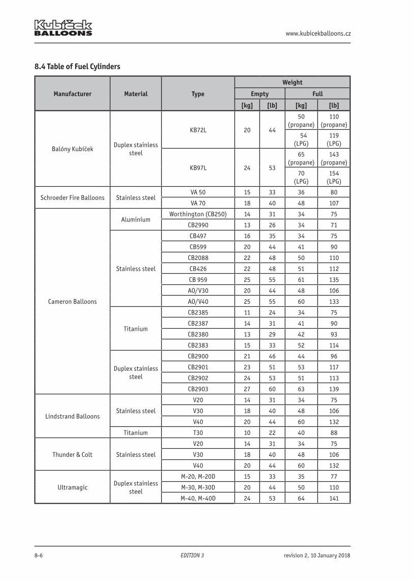
www.kubicekballoons.cz
8-6 EDITION 3 revision 2, 10 January 2018
8.4 Table of Fuel Cylinders
Manufacturer Material Type
Weight
Empty Full
[kg] [lb] [kg] [lb]
Balóny KubíčekDuplex stainless
steel
KB72L 20 44
50 (propane)
110 (propane)
5 54 (LPG)
119 (LPG)
KB97L 24 53
65 (propane)
143 (propane)
70 (LPG)
154 (LPG)
Schroeder Fire Balloons Stainless steelVA 50 15 33 36 80
VA 70 18 40 48 107
Cameron Balloons
AluminiumWorthington (CB250) 14 31 34 75
CB2990 13 26 34 71
Stainless steel
CB497 16 35 34 75
CB599 20 44 41 90
CB2088 22 48 50 110
CB426 22 48 51 112
CB 959 25 55 61 135
AO/V30 20 44 48 106
AO/V40 25 55 60 133
Titanium
CB2385 11 24 34 75
CB2387 14 31 41 90
CB2380 13 29 42 93
CB2383 15 33 52 114
Duplex stainless steel
CB2900 21 46 44 96
CB2901 23 51 53 117
CB2902 24 53 51 113
CB2903 27 60 63 139
Lindstrand BalloonsStainless steel
V20 14 31 34 75
V30 18 40 48 106
V40 20 44 60 132
Titanium T30 10 22 40 88
Thunder & Colt Stainless steel
V20 14 31 34 75
V30 18 40 48 106
V40 20 44 60 132
UltramagicDuplex stainless
steel
M-20, M-20D 15 33 35 77
M-30, M-30D 20 44 50 110
M-40, M-40D 24 53 64 141
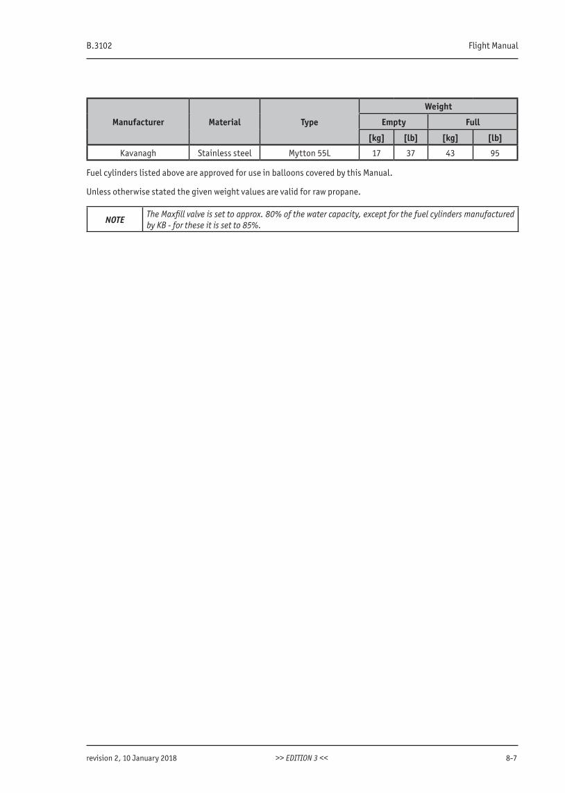
B.3102 Flight Manual
revision 2, 10 January 2018 >> EDITION 3 << 8-7
Manufacturer Material Type
Weight
Empty Full
[kg] [lb] [kg] [lb]
Kavanagh Stainless steel Mytton 55L 17 37 43 95
Fuel cylinders listed above are approved for use in balloons covered by this Manual.
Unless otherwise stated the given weight values are valid for raw propane.
NOTEThe Maxfill valve is set to approx. 80% of the water capacity, except for the fuel cylinders manufactured by KB - for these it is set to 85%.

www.kubicekballoons.cz
8-8 EDITION 3 revision 0, 15 May 2017
INTENTIONALLY LEFT BLANK
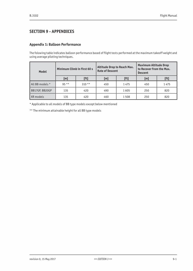
B.3102 Flight Manual
revision 0, 15 May 2017 >> EDITION 3 << 9-1
SECTION 9 - APPENDICES
Appendix 1: Balloon Performance
The folowing table indicates balloon performance based of flight tests performed at the maximum takeoff weight and using average piloting techniques.
ModelMinimum Climb in first 60 s Altitude Drop to Reach Max.
Rate of Descent
Maximum Altitude Drop to Recover from the Max. Descent
[m] [ft] [m] [ft] [m] [ft]
All BB models * 95 ** 310 ** 450 1 475 450 1 475
BB17GP, BB20GP 135 420 490 1 605 250 820
XR models 135 420 460 1 508 250 820
* Applicable to all models of BB type models except below mentioned
** The minimum attainable height for all BB type models
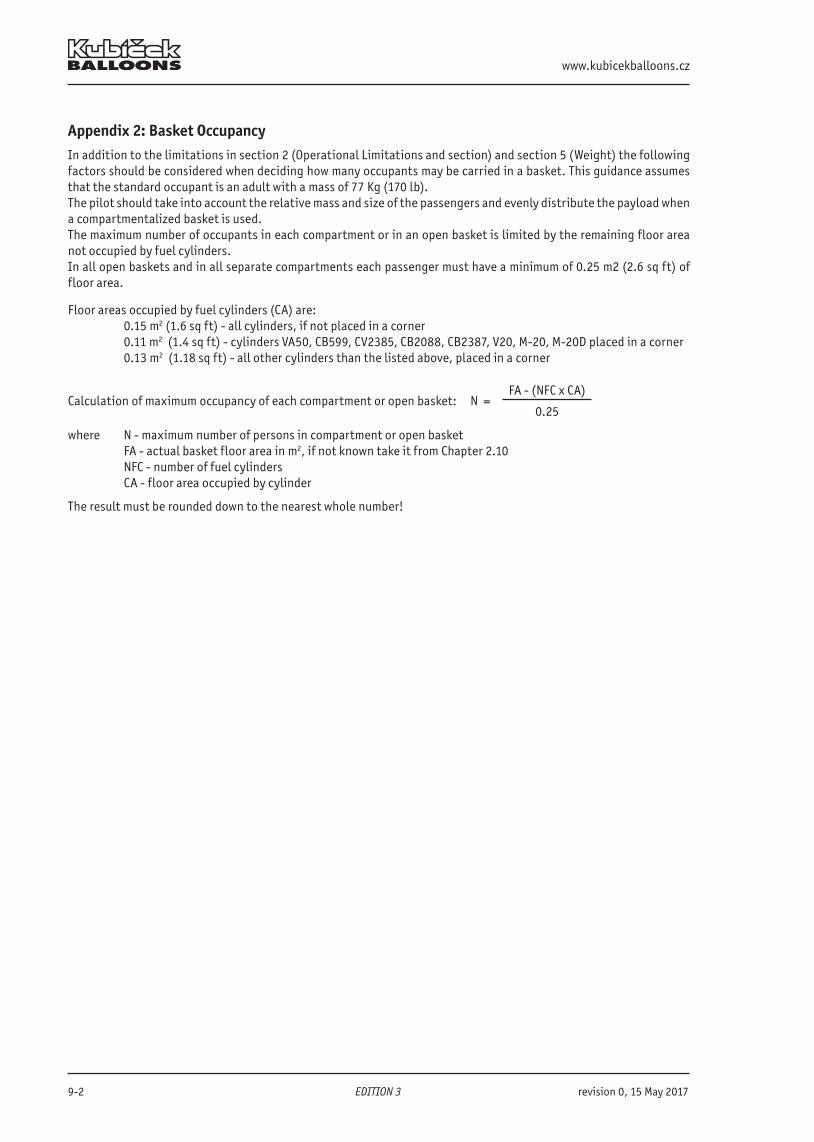
www.kubicekballoons.cz
9-2 EDITION 3 revision 0, 15 May 2017
Appendix 2: Basket OccupancyIn addition to the limitations in section 2 (Operational Limitations and section) and section 5 (Weight) the followingfactors should be considered when deciding how many occupants may be carried in a basket. This guidance assumes that the standard occupant is an adult with a mass of 77 Kg (170 lb).The pilot should take into account the relative mass and size of the passengers and evenly distribute the payload when a compartmentalized basket is used.The maximum number of occupants in each compartment or in an open basket is limited by the remaining floor area not occupied by fuel cylinders.In all open baskets and in all separate compartments each passenger must have a minimum of 0.25 m2 (2.6 sq ft) of floor area.
Floor areas occupied by fuel cylinders (CA) are: 0.15 m2 (1.6 sq ft) - all cylinders, if not placed in a corner 0.11 m2 (1.4 sq ft) - cylinders VA50, CB599, CV2385, CB2088, CB2387, V20, M-20, M-20D placed in a corner 0.13 m2 (1.18 sq ft) - all other cylinders than the listed above, placed in a corner
Calculation of maximum occupancy of each compartment or open basket: N = FA - (NFC x CA)
0.25
where N - maximum number of persons in compartment or open basket FA - actual basket floor area in m2, if not known take it from Chapter 2.10 NFC - number of fuel cylinders CA - floor area occupied by cylinder
The result must be rounded down to the nearest whole number!
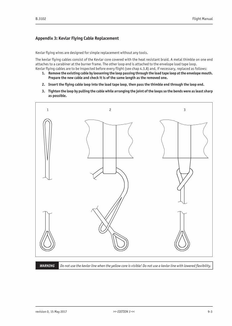
B.3102 Flight Manual
revision 0, 15 May 2017 >> EDITION 3 << 9-3
Appendix 3: Kevlar Flying Cable Replacement
Kevlar flying wires are designed for simple replacement without any tools.
The kevlar flying cables consist of the Kevlar core covered with the heat resistant braid. A metal thimble on one end attaches to a carabiner at the burner frame. The other loop end is attached to the envelope load tape loop.Kevlar flying cables are to be inspected before every flight (see chap 4.3.8) and, if necessary, replaced as follows:
1. Remove the existing cable by loosening the loop passing through the load tape loop at the envelope mouth. Prepare the new cable and check it is of the same length as the removed one.
2. Insert the flying cable loop into the load tape loop, then pass the thimble end through the loop end.
3. Tighten the loop by pulling the cable while arranging the joint of the loops so the bends were as least sharp as possible.
1 2 3
WARNING Do not use the kevlar line when the yellow core is visible! Do not use a kevlar line with lowered flexibility.
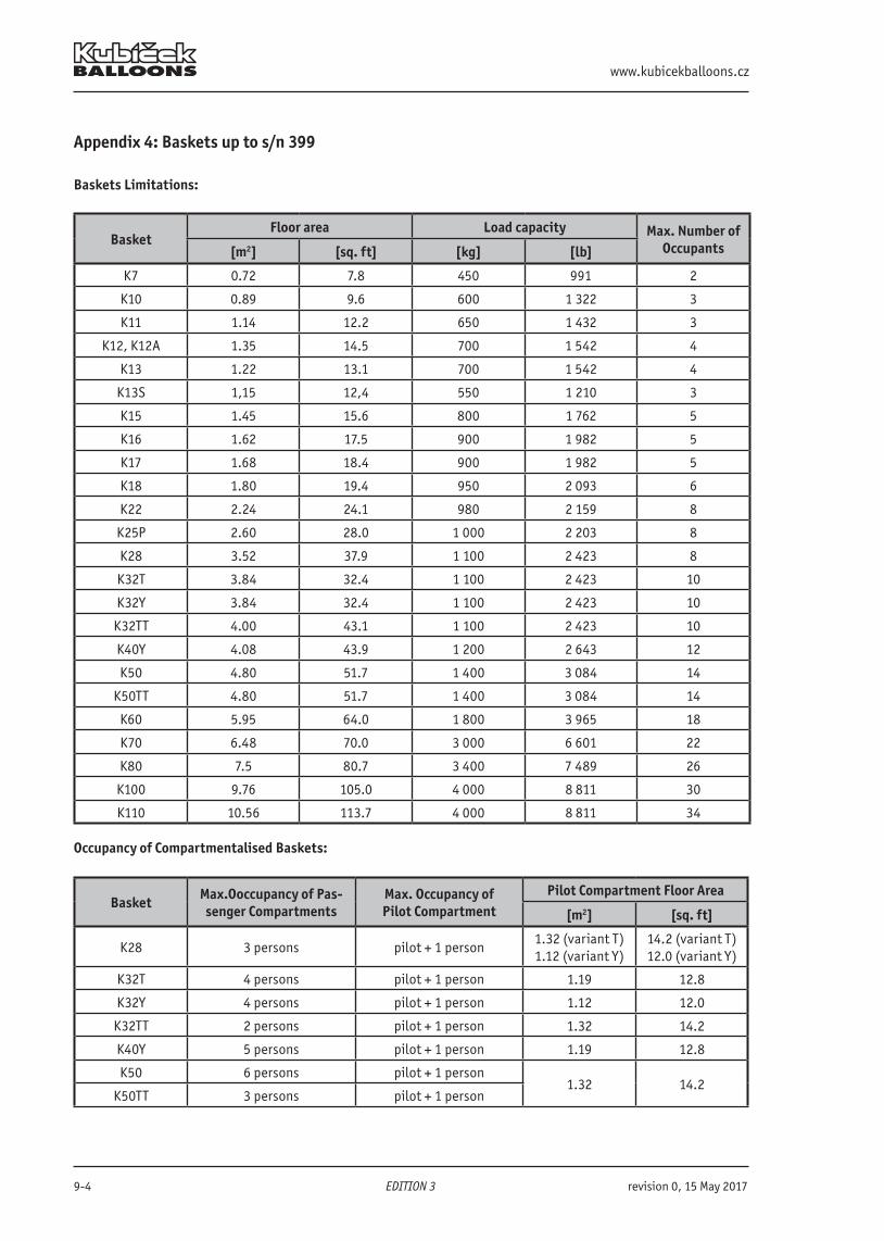
www.kubicekballoons.cz
9-4 EDITION 3 revision 0, 15 May 2017
Appendix 4: Baskets up to s/n 399
Baskets Limitations:
BasketFloor area Load capacity Max. Number of
Occupants[m2] [sq. ft] [kg] [lb]
K7 0.72 7.8 450 991 2
K10 0.89 9.6 600 1 322 3
K11 1.14 12.2 650 1 432 3
K12, K12A 1.35 14.5 700 1 542 4
K13 1.22 13.1 700 1 542 4
K13S 1,15 12,4 550 1 210 3
K15 1.45 15.6 800 1 762 5
K16 1.62 17.5 900 1 982 5
K17 1.68 18.4 900 1 982 5
K18 1.80 19.4 950 2 093 6
K22 2.24 24.1 980 2 159 8
K25P 2.60 28.0 1 000 2 203 8
K28 3.52 37.9 1 100 2 423 8
K32T 3.84 32.4 1 100 2 423 10
K32Y 3.84 32.4 1 100 2 423 10
K32TT 4.00 43.1 1 100 2 423 10
K40Y 4.08 43.9 1 200 2 643 12
K50 4.80 51.7 1 400 3 084 14
K50TT 4.80 51.7 1 400 3 084 14
K60 5.95 64.0 1 800 3 965 18
K70 6.48 70.0 3 000 6 601 22
K80 7.5 80.7 3 400 7 489 26
K100 9.76 105.0 4 000 8 811 30
K110 10.56 113.7 4 000 8 811 34
Occupancy of Compartmentalised Baskets:
Basket Max.Ooccupancy of Pas-senger Compartments
Max. Occupancy of Pilot Compartment
Pilot Compartment Floor Area
[m2] [sq. ft]
K28 3 persons pilot + 1 person1.32 (variant T)1.12 (variant Y)
14.2 (variant T)12.0 (variant Y)
K32T 4 persons pilot + 1 person 1.19 12.8
K32Y 4 persons pilot + 1 person 1.12 12.0
K32TT 2 persons pilot + 1 person 1.32 14.2
K40Y 5 persons pilot + 1 person 1.19 12.8
K50 6 persons pilot + 1 person1.32 14.2
K50TT 3 persons pilot + 1 person
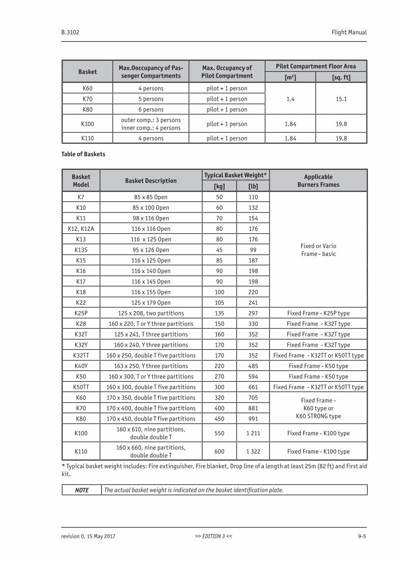
B.3102 Flight Manual
revision 0, 15 May 2017 >> EDITION 3 << 9-5
Basket Max.Ooccupancy of Pas-senger Compartments
Max. Occupancy of Pilot Compartment
Pilot Compartment Floor Area
[m2] [sq. ft]
K60 4 persons pilot + 1 person
1.4 15.1K70 5 persons pilot + 1 person
K80 6 persons pilot + 1 person
K100outer comp.: 3 personsinner comp.: 4 persons
pilot + 1 person 1.84 19.8
K110 4 persons pilot + 1 person 1.84 19.8
Table of Baskets
Basket Model Basket Description
Typical Basket Weight* ApplicableBurners Frames[kg] [lb]
K7 85 x 85 Open 50 110
Fixed or VarioFrame - basic
K10 85 x 100 Open 60 132
K11 98 x 116 Open 70 154
K12, K12A 116 x 116 Open 80 176
K13 116 x 125 Open 80 176
K13S 95 x 126 Open 45 99
K15 116 x 125 Open 85 187
K16 116 x 140 Open 90 198
K17 116 x 145 Open 90 198
K18 116 x 155 Open 100 220
K22 125 x 179 Open 105 241
K25P 125 x 208, two partitions 135 297 Fixed Frame - K25P type
K28 160 x 220, T or Y three partitions 150 330 Fixed Frame - K32T type
K32T 125 x 241, T three partitions 160 352 Fixed Frame - K32T type
K32Y 160 x 240, Y three partitions 170 352 Fixed Frame - K32T type
K32TT 160 x 250, double T five partitions 170 352 Fixed Frame - K32TT or K50TT type
K40Y 163 x 250, Y three partitions 220 485 Fixed Frame - K50 type
K50 160 x 300, T or Y three partitions 270 594 Fixed Frame - K50 type
K50TT 160 x 300, double T five partitions 300 661 Fixed Frame - K32TT or K50TT type
K60 170 x 350, double T five partitions 320 705 Fixed Frame -K60 type or
K60 STRONG typeK70 170 x 400, double T five partitions 400 881
K80 170 x 450, double T five partitions 450 991
K100160 x 610, nine partitions,
double double T550 1 211 Fixed Frame - K100 type
K110160 x 660, nine partitions,
double double T600 1 322 Fixed Frame - K100 type
* Typical basket weight includes: Fire extinguisher, Fire blanket, Drop line of a length at least 25m (82 ft) and First aid kit.
NOTE The actual basket weight is indicated on the basket identification plate.
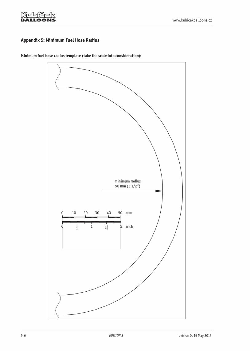
www.kubicekballoons.cz
9-6 EDITION 3 revision 0, 15 May 2017
Appendix 5: Minimum Fuel Hose Radius
Minimum fuel hose radius template (take the scale into consideration):
minimum radius 90 mm (3 1/2“)
B.3102 Flight Manual
revision 0, 15 May 2017 >> EDITION 3 << 9-7
Appendix 6: Limits for baskets K32T or K40YAdditional limits apply when baskets K32T or K40Y fitted with burner frames without the symbol S/N before their serial number are used:The maximum wind speed for take-off for BB60 and BB60Z balloon is 6.0 m/s (11.7 kts).The maximum wind speed for take-off for BB70Z is 5.5 m/s (10.7 kts).See also Chapter 2.24.
www.kubicekballoons.cz
9-8 EDITION 3 revision 0, 15 May 2017
INTENTIONALLY LEFT BLANK
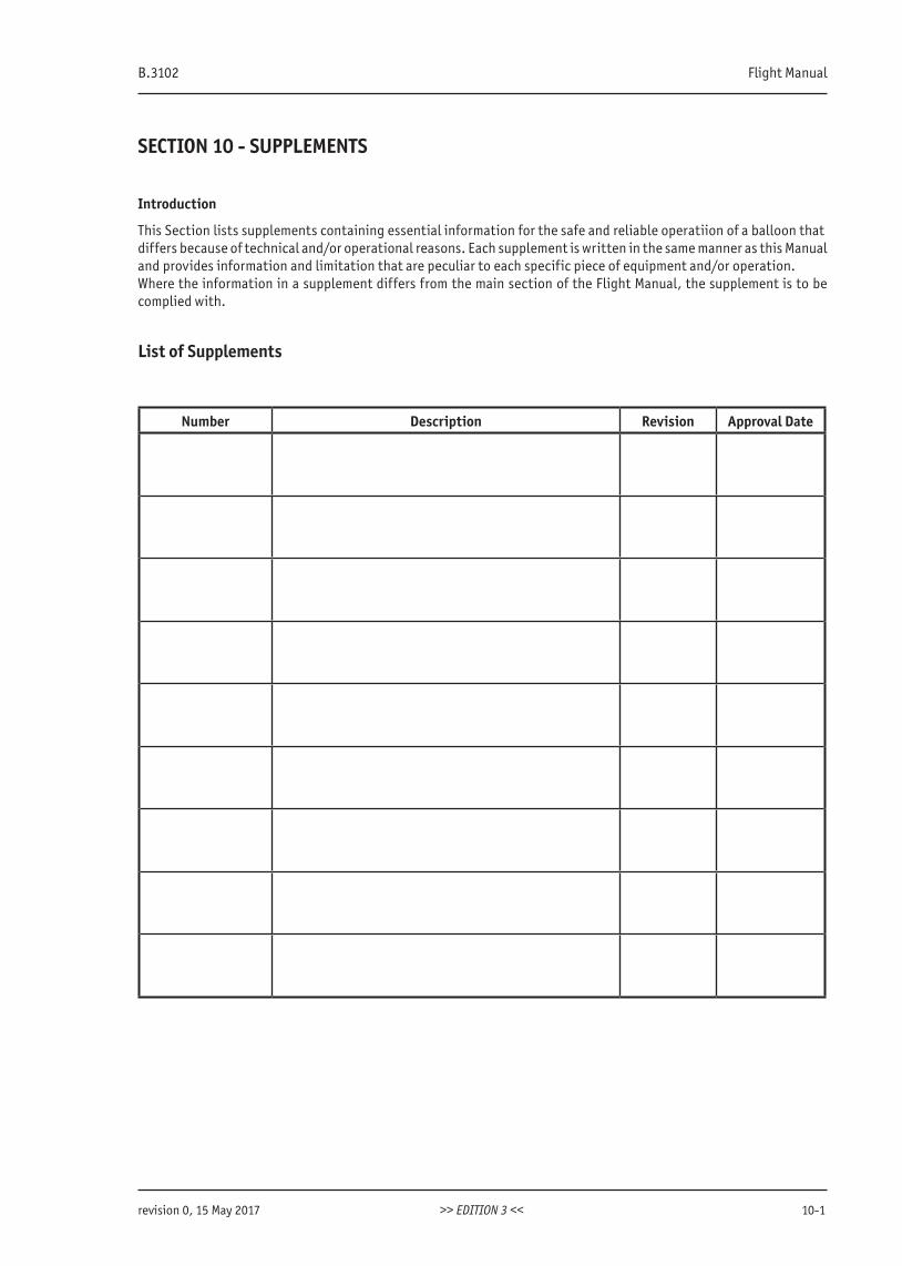
B.3102 Flight Manual
revision 0, 15 May 2017 >> EDITION 3 << 10-1
SECTION 10 - SUPPLEMENTS
Introduction
This Section lists supplements containing essential information for the safe and reliable operatiion of a balloon thatdiffers because of technical and/or operational reasons. Each supplement is written in the same manner as this Manualand provides information and limitation that are peculiar to each specific piece of equipment and/or operation.Where the information in a supplement differs from the main section of the Flight Manual, the supplement is to be complied with.
List of Supplements
Number Description Revision Approval Date
LET US HELP YOU!
In case that you have any suggestion, difficulty, problem or comment, please contact ourtechnical department at:
[email protected]+420 545 422 638
BALÓNY KUBÍĆEK spol. s r. o.e-mail: [email protected] • www.kubicekballoons.eu
Seat: Brno 602 00 • Francouzská 81 • Czech RepublicOffice: Brno 614 00 • Jarní 2a • Czech Republictel.: +420 545 422 620, • fax: +420 545 422 621
© Copyright BALONY KUBÍČEK spol. s r.o.2018