Embed Size (px)
Citation preview
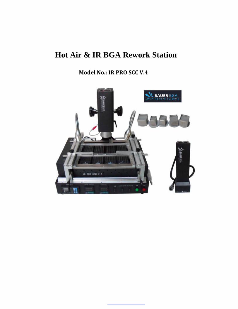
Hot Air & IR BGA Rework Station
�Model No.: IR PRO SCC V.4�
Directory 1. The instructions on installation site and operating precautions
2. Introduction of Rework Station IR PRO SCC V.4
3. The operation instructions
4. PC410 Programmable temperature control instruction
5. 100 Temp control meter Introduction
6. Temperature profile setting introduction

1. The instructions on installation site and operating precautions Installation sites
In order to ensure safety and avoid possible damages to rework stations, it should be installed
in the following conditions of the environment places。
◆ Away from inflammables.
◆ Free from splashing of water or other liquids.
◆ Free from the direct airflow impact from air conditioner, heater or ventilator.
◆ With good ventilation, dry and free from excessive dust.
◆ Stable and flat location that is free from vibration and shock.
Power Supply
Supply voltage requirements are as follows:
◆ The use of smaller power supply voltage fluctuation
Voltage fluctuation: 220~240V±10。。
Frequency fluctuations: 50/60Hz±0.3。。
Space requirements
◆ To ensure easy operation and maintenance of rework station, parts replacement and repair,
please according to space requirements under the proposed。
About 1.0 meters L * 1.3 meters W
Attention:
To facilitate operation and maintenance when we have to move the machine
forward/backward and turn it, it is required to reserve a room that is >300mm far from the
back.

Follow the following precautions, when operating the machine.
◆ Please place the rework station in a smooth-air work environment without wind and with less
dust;
◆ Do not use any object to knock or your hands to sway heating plates;
◆ Avoid electric fans or other equipments blowing towards the rework station while it is
working, or else, it may cause the heater’s abnormal temperature rise, and the work piece
will get burnt.
◆ Do not place any heavy object on machine control box;
◆ The high temperature heating zone should not directly touch any object, or else, it may lead to
fires or explosions; the PCB board to be repaired should be placed on PCB board support rack;
◆ Don’t shake the machine; and put it lightly down when moving it;
machine;
◆ Do not try to change the rework station, otherwise, it will cause fire or electric shock;
◆ Do not remove the electric cabinet panel or cover, there is high-voltage components inside,
which may lead to electric shocks;
◆ In case the metal or liquid falls into the station while it’s working, shut off power and pull
out the plug. Clean away all the dirt after the machine cools down. It will give out bad
smell if there is still dirt when it restarts.
◆ When there is abnormal temperature rise or smoke coming out, cut off the power immediately
fires or electrical shocks;
station or it runs over them, or else, it may lead to machine fault or cause fire or electric shock。
Attention:
The rework station under the normal usage will produce a little peculiar smell, in order
to ensure a comfortable, healthy and safe operating environment, please keep indoor and outdoor air
circulation。
◆ Don't use your hands to touch the high-temperature heating zone, or else, you will burn your hands
◆ While machine working, combustible spray, liquid or gas s h o u l d ` n t be available around the
and inform technical staff to repair. If y o u continuing using machine , it may cause
◆ Please notice that there should`nt be any power wire or communication cables beneath the rework
◆ Power supply should be cut off and stop using machine;
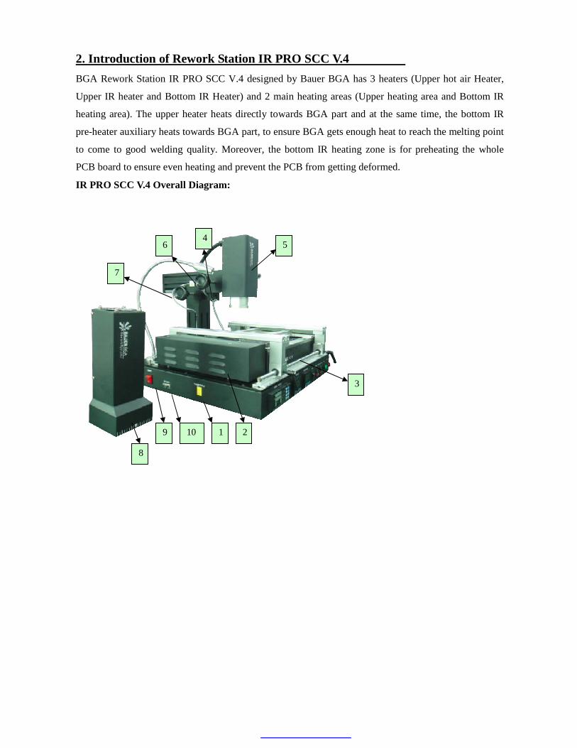
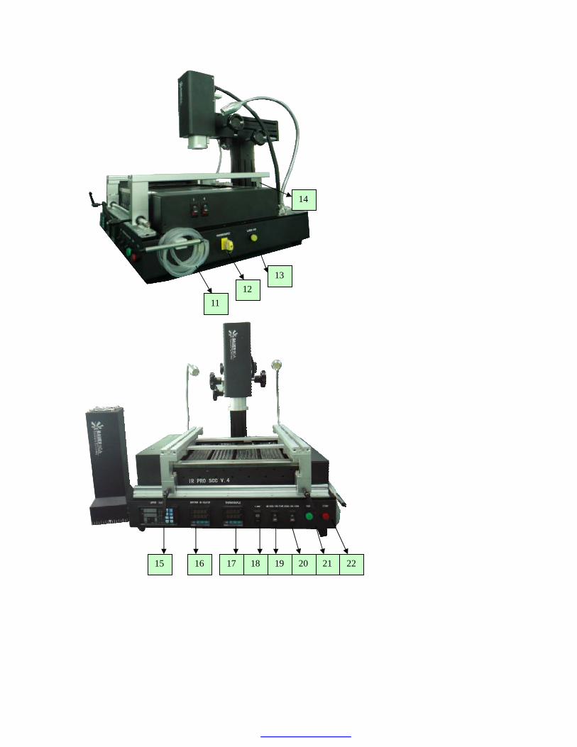
2. Introduction of Rework Station IR PRO SCC V.4 BGA Rework Station IR PRO SCC V.4 designed by Bauer BGA has 3 heaters (Upper hot air Heater,
Upper IR heater and Bottom IR Heater) and 2 main heating areas (Upper heating area and Bottom IR
heating area). The upper heater heats directly towards BGA part and at the same time, the bottom IR
pre-heater auxiliary heats towards BGA part, to ensure BGA gets enough heat to reach the melting point
to come to good welding quality. Moreover, the bottom IR heating zone is for preheating the whole
PCB board to ensure even heating and prevent the PCB from getting deformed.
IR PRO SCC V.4 Overall Diagram:
5 4
3
2 1
6
7
8
9 10

Parts name:
1. Inner thermocouple port for IR and Hot air
2. Cross flow cooling fan
3. Bottom preheating area
4. Laser pointer
5. Upper hot air heating head
6. Knob for adjusting the upper head up/down
7. Knob for adjusting the upper head forward/backward
8. IR upper heating head
9. Power switch
11. Vacuum suction pen
12. Outer thermocouple port
13. Laser light on/off switch
14. PCB supporting mechanism
15. Upper heater: Upper head programmable temperature control meter
16. Bottom heater: Bottom IR heater temperature control meter
17. Thermocouple: Real-time temperature measurement meter
18. LED lamp on/off switch
19. Cooling fan for IR heater head
20. Cross flow fan for cooling down PCB
21. Start button
22. Stop button
10. Communication port (RS232)

3. The operation instructions
1、Usage and heating system: IR PRO SCC V.4 is mainly used for Hot-air & IR BGA / IC
desoldeirng and soldering. BGA rework station adopts programmable multi-stage temperature
controller to control the main heating head; the heating temperature and time can be set
far infrared heating panels to ensure evenly heating towards PCB and prevent it from
deformation to ensure a good welding effect. This machine is equipped with different sizes of
hot air nozzles (nozzle sizes are customized)。
2、Temperature setting:
BGA desoldering:
BGA
BGA soldering:
3、Desoldering:put PCB onto the PCB support racks (as shown as in Fig. 1) , and then press the
“start” switch (when using IR head to desolder, press “start” switch and open the IR cooling fan
at the same time); when the temperature profile running finishes, use vacuum pen to absorb the
BGA away from the PCB board; next, turn on the machine cross flow cooling fan to cool down
the PCB. After that, take away PCB from the clamping device and close the cooling fan.
Fig. 1:
specifically; hot air heating uses high-quality heater from Bauer the bottom is a large-area
Preheating / Preheating / Preheating / Melting temperature / Vacuum suction pen picks up
Preheating / Preheating / Preheating / Soldering / Cooling / Soldering finish
The right wire sensor
Clamping device
IR upper head
The left wire sensor
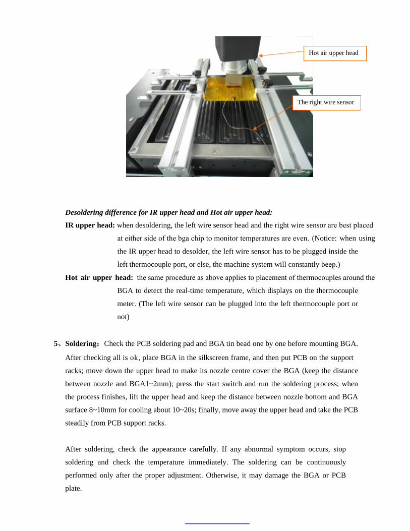
Desoldering difference for IR upper head and Hot air upper head:
meter. (The left wire sensor can be plugged into the left thermocouple port or
not)
5、Soldering:Check the PCB soldering pad and BGA tin bead one by one before mounting BGA.
racks; move down the upper head to make its nozzle centre cover the BGA (keep the distance
between nozzle and BGA1~2mm); press the start switch and run the soldering process; when
the process finishes, lift the upper head and keep the distance between nozzle bottom and BGA
surface 8~10mm for cooling about 10~20s; finally, move away the upper head and take the PCB
steadily from PCB support racks.
After soldering, check the appearance carefully. If any abnormal symptom occurs, stop
soldering and check the temperature immediately. The soldering can be continuously
performed only after the proper adjustment. Otherwise, it may damage the BGA or PCB
plate.
The right wire sensor
Hot air upper head
left thermocouple port, or else, the machine system will constantly beep.)
at either side of the bga chip to monitor temperatures are even. (Notice: when using
IR upper head: when desoldering, the left wire sensor head and the right wire sensor are best placed
BGA to detect the real-time temperature, which displays on the thermocouple
the IR upper head to desolder, the left wire sensor has to be plugged inside the
Hot air upper head: the same procedure as above applies to placement of thermocouples around the
After checking all is ok, place BGA in the silkscreen frame, and then put PCB on the support

6、Features:
components around.
When using IR upper head, please cover the components around with silver paper within the
range of infrared radiation
Shortcut: heating time and temperature are digitally displayed; the setting is convenient,
be adjusted in X and Y direction, and the upper head can work at any angle and height.
7、Main parameters:
PCB size: MAX 380mmW*420mmL
PCB thickness: Unlimited
Min BGA size: 1mm × 1 mm
Max BGA size: 60mm × 60 mm
Upper power: hot air, 800 W; IR, 500W;
Bottom power: 2000 W;
Security: when using hot air upper head, hot air only heats towards and won’t do harm to
intuitive and accurate to optimize the repair time to the shortest possible time.
Convenience: it can quickly replace a different hot air nozzle, PCB on the positioning racks can

4. PC410 Programmable temperature control instruction
1. Panel introduction
S.N Item Function
(Parameter/Setting key)
Parameter setting key
(Auto/Manual key)
Auto/Manual switch key
(Up key)
Increase parameter value
1
(Down key)
Reduce parameter value
(Pattern key)
Selects the program pattern number
(Run/Program key)
Starts the program, changes the mode from fixed value control to
program control
(Set/Program key)
Program parameter setup
2
(Display Selection key)
Changes the indication on SV/MV/TIME display
OUT1 (Output1 indicator)
The LED indicator is lit When ouput1 is ON 3
OUT2 (Output2 indicator)
Bauer BGA Reworking Made Simple

The LED indicator is lit When ouput2 is ON
4 STEP (Step number display)
Indicate the step number of the currently-running profile program
5 PRO
(Program monitor indicator)
During program control, “/”is lit when the PV is rising
During program control, “-“is lit when the PV is constant
During program control, “\” is lit when the PV is falling
6 PTN (Profile group No. display)
Indicate the profile program group number
7 RUN (Program control running indicator)
The LED indicator is lit during profile program control
8 PV Display (PV display)
Indicate the practically-measured temperature value
9 SV/MV/TIME
Display
(PV display)
It indicates the Setting value(SV), Manipulating value(MV), or
Time(TIME)
(The display can be changed by the ‘DISP SELECT’ key)
TIME (TIME indicator)
It is lit when the time(TIME) is being displayed on the lower display
MV (MV indicator)
It is lit when the time(TIME) is being displayed on the lower display 10
SV
(SV indicator)
It is lit when the Setting Value(SV) is being displayed on the lower
display
COM
(Communication indicator)
It flashes when the meter controller is in active communication with a
host computer.
MAN (Manual control indicator)
It is lit in manual control
11
AL1 (Alarm1 output indicator)
It is lit when the Alarm 1 output is ON
Bauer BGA Reworking Made Simple
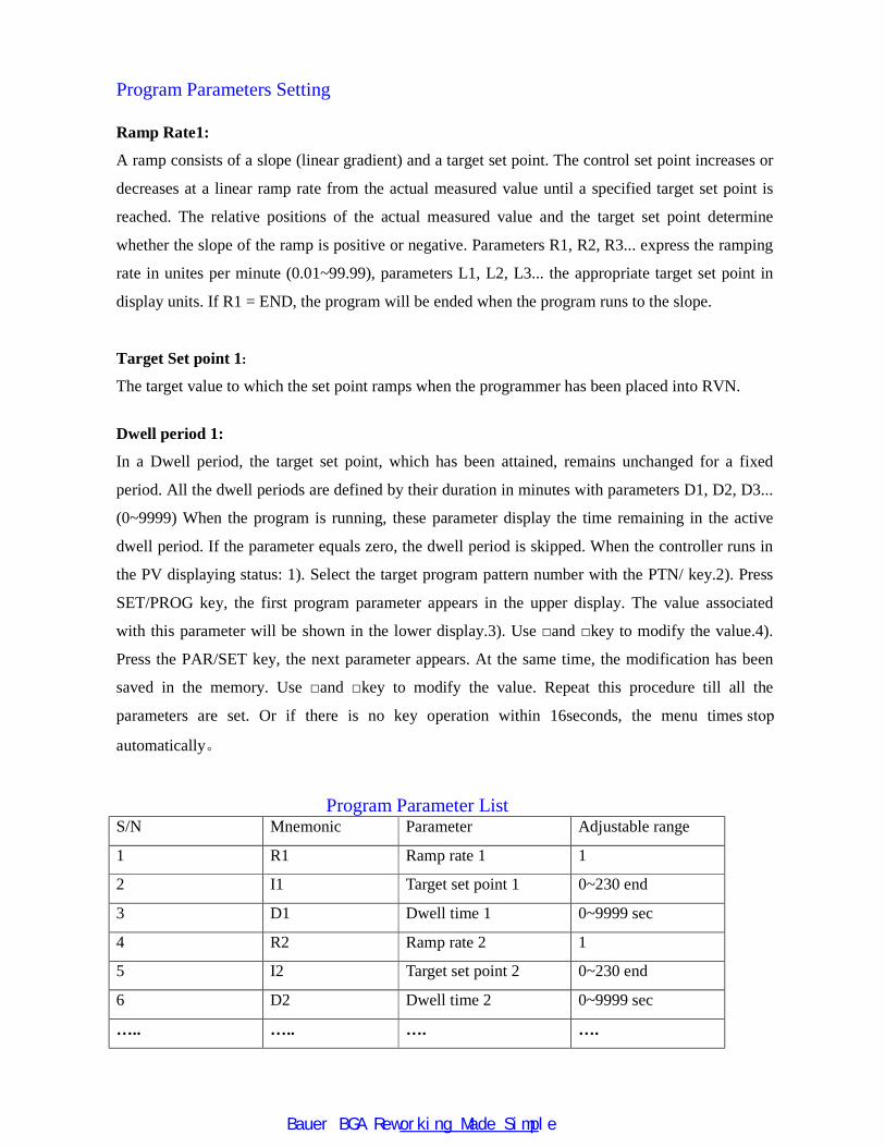
Program Parameters Setting Ramp Rate1:
A ramp consists of a slope (linear gradient) and a target set point. The control set point increases or
decreases at a linear ramp rate from the actual measured value until a specified target set point is
reached. The relative positions of the actual measured value and the target set point determine
whether the slope of the ramp is positive or negative. Parameters R1, R2, R3... express the ramping
rate in unites per minute (0.01~99.99), parameters L1, L2, L3... the appropriate target set point in
display units. If R1 = END, the program will be ended when the program runs to the slope.
Target Set point 1:
The target value to which the set point ramps when the programmer has been placed into RVN.
Dwell period 1:
In a Dwell period, the target set point, which has been attained, remains unchanged for a fixed
period. All the dwell periods are defined by their duration in minutes with parameters D1, D2, D3...
(0~9999) When the program is running, these parameter display the time remaining in the active
dwell period. If the parameter equals zero, the dwell period is skipped. When the controller runs in
the PV displaying status: 1). Select the target program pattern number with the PTN/ key.2). Press
SET/PROG key, the first program parameter appears in the upper display. The value associated
with this parameter will be shown in the lower display.3). Use □and □key to modify the value.4).
Press the PAR/SET key, the next parameter appears. At the same time, the modification has been
saved in the memory. Use □and □key to modify the value. Repeat this procedure till all the
automatically。
Program Parameter List S/N Mnemonic Parameter Adjustable range
1 R1 Ramp rate 1 1
2 I1 Target set point 1 0~230 end
3 D1 Dwell time 1 0~9999 sec
4 R2 Ramp rate 2 1
5 I2 Target set point 2 0~230 end
6 D2 Dwell time 2 0~9999 sec
….. ….. …. ….
parameters are set. Or if there is no key operation within 16seconds, the menu times stop
Bauer BGA Reworking Made Simple
HB 230
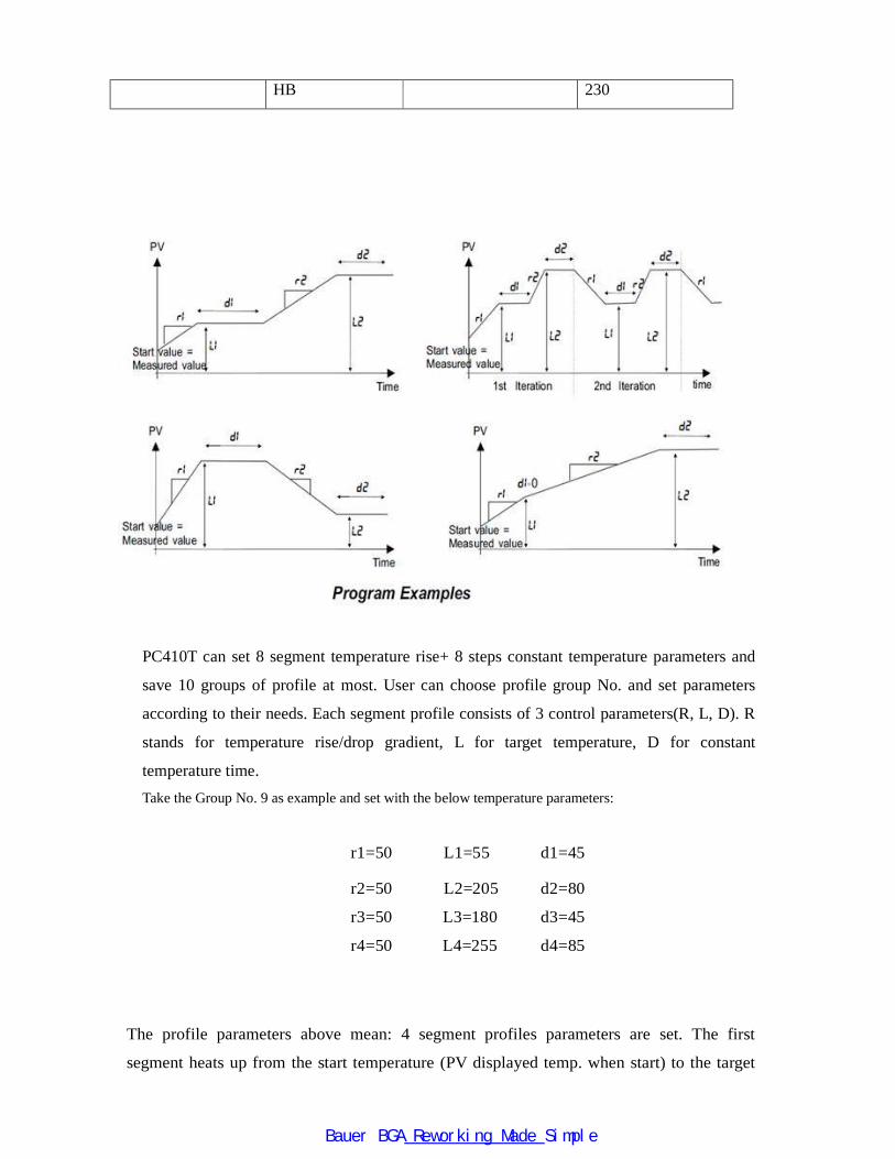
PC410T can set 8 segment temperature rise+ 8 steps constant temperature parameters and
save 10 groups of profile at most. User can choose profile group No. and set parameters
according to their needs. Each segment profile consists of 3 control parameters(R, L, D). R
stands for temperature rise/drop gradient, L for target temperature, D for constant
temperature time. Take the Group No. 9 as example and set with the below temperature parameters:
r1=50 L1=55 d1=45
r2=50
r3=50
r4=50
L2=205
L3=180
L4=255
d2=80
d3=45
d4=85
The profile parameters above mean: 4 segment profiles parameters are set. The first
segment heats up from the start temperature (PV displayed temp. when start) to the target
Bauer BGA Reworking Made Simple
temperature 55 ℃ at speed of 50℃/s. It maintains 55℃ for 45s and then enters the second
segment which is for heating up from 55℃ to target temp 205℃ at speed of 50℃/s. Then it
maintains 205℃ for 80s and then enters the 3rd segment which is for cooling down from
205℃ to 180℃ at speed of 50℃/s. Then it maintains 180℃ for 45s. Later, it enters the 4th
segment which is for heating up from 180℃ to 255℃ and then remains 255℃ for 85s. The
profile running ends.
The calculation formula of profile running time:
Total running time= (L1-starting temp.)/r1+d1+(L2-L1)/r2+d2+(L3-L2)/r3+d3+(L4-L3)
/r4+d4+(L5-L4)/r5+d5+(L6-L5)/r6+d6+(L7-L6)/r7+d7+(L8-L7)/r8+d8(S)。
So the profile running time is (suppose the start temp. is 25 ℃):(55-25)/50+45+(205-55)
/50+80+(205-180)/50+45+(255-180)/50+85=260.4(S)。
Bauer BGA Reworking Made Simple
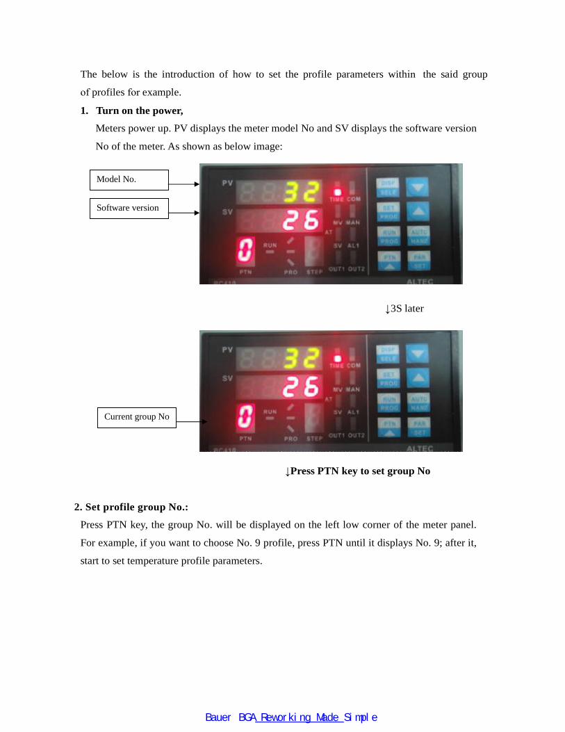
1. Turn on the power,
Meters power up. PV displays the meter model No and SV displays the software version
No of the meter. As shown as below image:
↓3S later
↓Press PTN key to set group No
2. Set profile group No.:
Press PTN key, the group No. will be displayed on the left low corner of the meter panel.
For example, if you want to choose No. 9 profile, press PTN until it displays No. 9; after it,
start to set temperature profile parameters.
Model No.
Software version
Current group No
The below is the introduction of how to set the profile parameters within the said group
of profiles for example.
Bauer BGA Reworking Made Simple
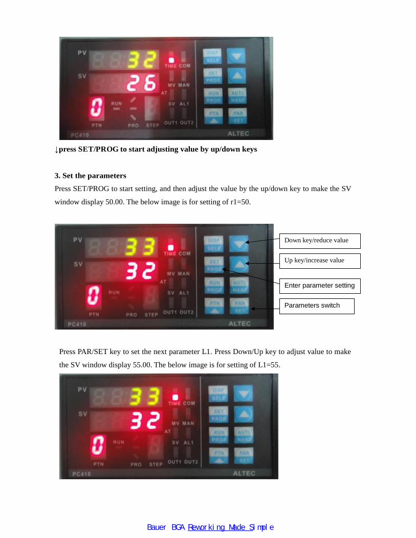
↓press SET/PROG to start adjusting value by up/down keys
3. Set the parameters
Press SET/PROG to start setting, and then adjust the value by the up/down key to make the SV
window display 50.00. The below image is for setting of r1=50.
Press PAR/SET key to set the next parameter L1. Press Down/Up key to adjust value to make
the SV window display 55.00. The below image is for setting of L1=55.
Down key/reduce value
Up key/increase value
Enter parameter setting
Parameters switch
Bauer BGA Reworking Made Simple
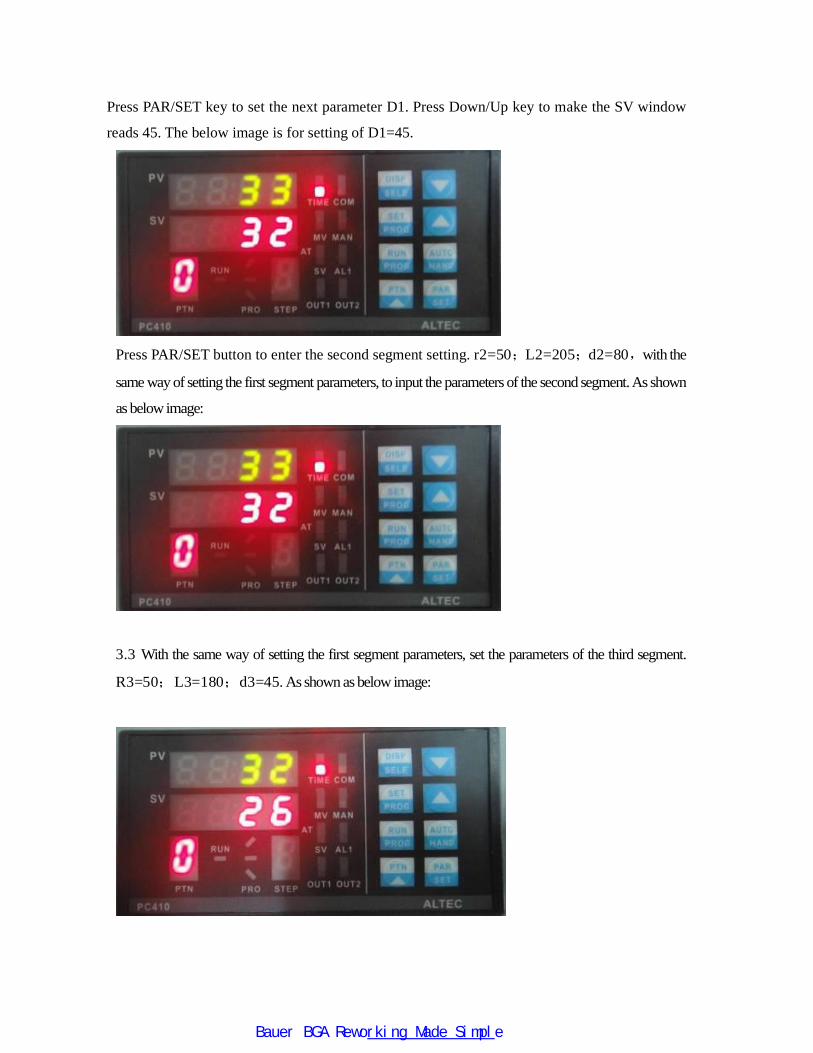
Press PAR/SET key to set the next parameter D1. Press Down/Up key to make the SV window
reads 45. The below image is for setting of D1=45.
Press PAR/SET button to enter the second segment setting. r2=50;L2=205;d2=80,with the
same way of setting the first segment parameters, to input the parameters of the second segment. As shown
as below image:
3.3 With the same way of setting the first segment parameters, set the parameters of the third segment.
R3=50;L3=180;d3=45. As shown as below image:
Bauer BGA Reworking Made Simple
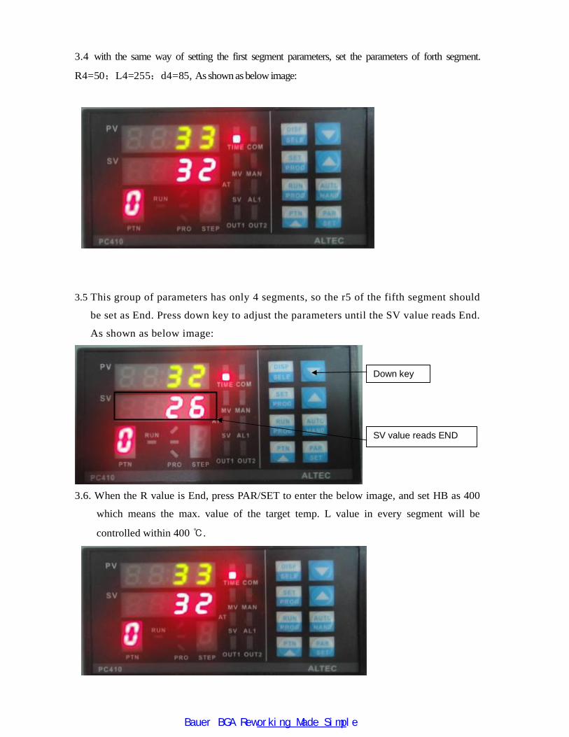
3.4 with the same way of setting the first segment parameters, set the parameters of forth segment.
R4=50;L4=255;d4=85, As shown as below image:
3.5 This group of parameters has only 4 segments, so the r5 of the fifth segment should
be set as End. Press down key to adjust the parameters until the SV value reads End.
As shown as below image:
3.6. When the R value is End, press PAR/SET to enter the below image, and set HB as 400
which means the max. value of the target temp. L value in every segment will be
controlled within 400 ℃.
Down key
SV value reads END
Bauer BGA Reworking Made Simple
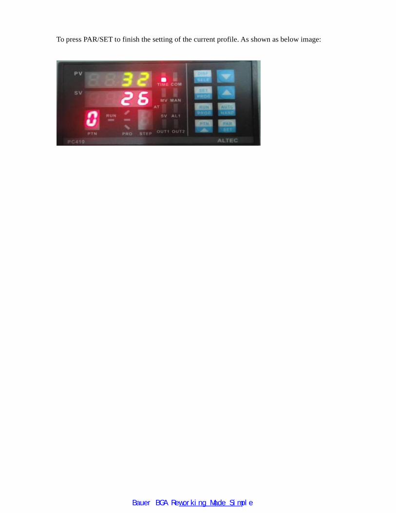
To press PAR/SET to finish the setting of the current profile. As shown as below image:
Bauer BGA Reworking Made Simple
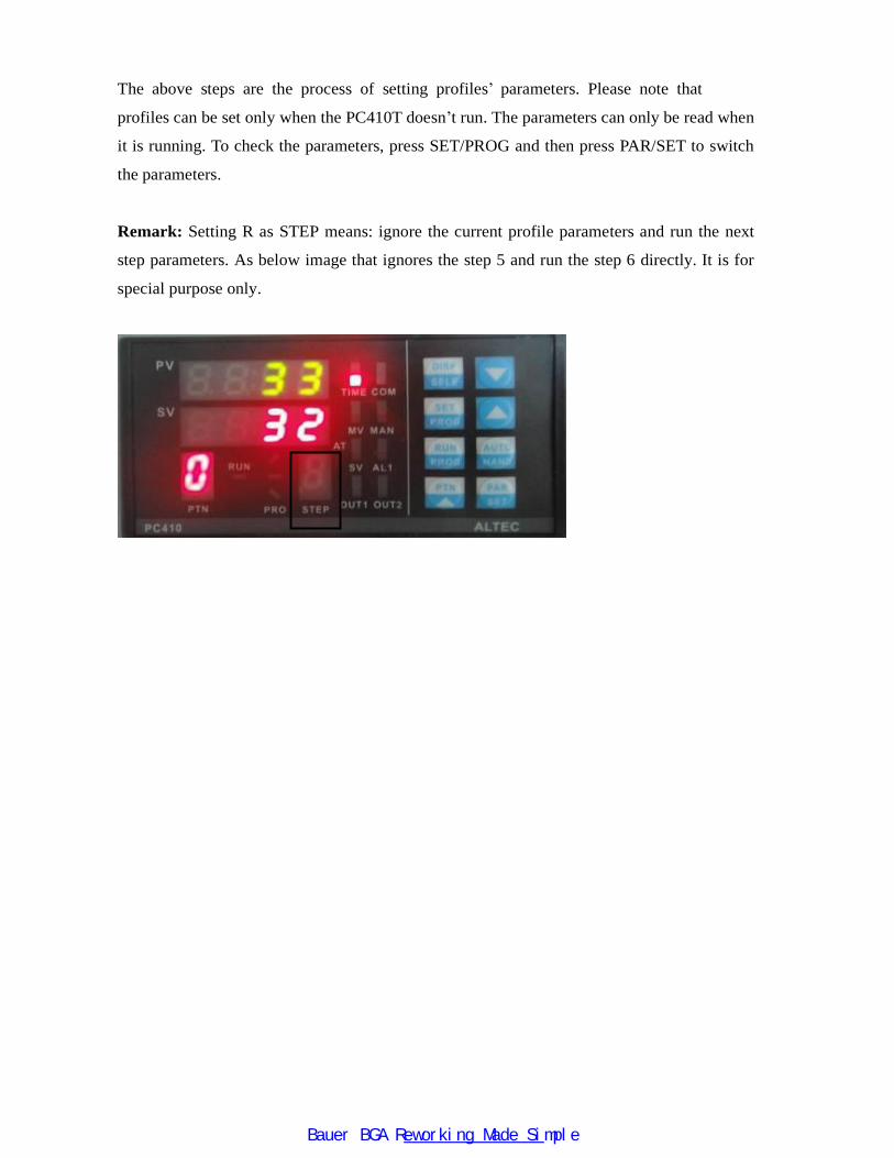
profiles can be set only when the PC410T doesn’t run. The parameters can only be read when
it is running. To check the parameters, press SET/PROG and then press PAR/SET to switch
the parameters.
Remark: Setting R as STEP means: ignore the current profile parameters and run the next
step parameters. As below image that ignores the step 5 and run the step 6 directly. It is for
special purpose only.
The above steps are the process of setting profiles’ parameters. Please note that
Bauer BGA Reworking Made Simple
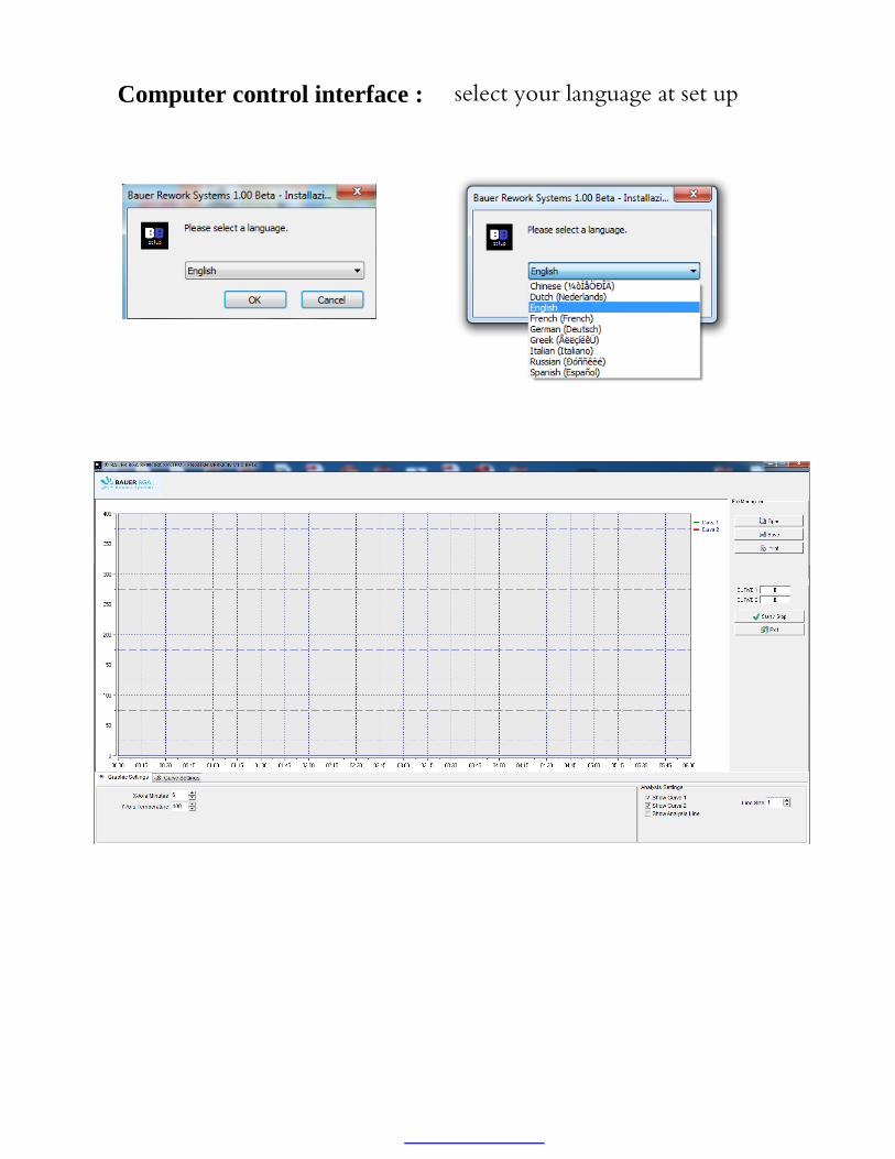
Computer control interface : select your language at set up
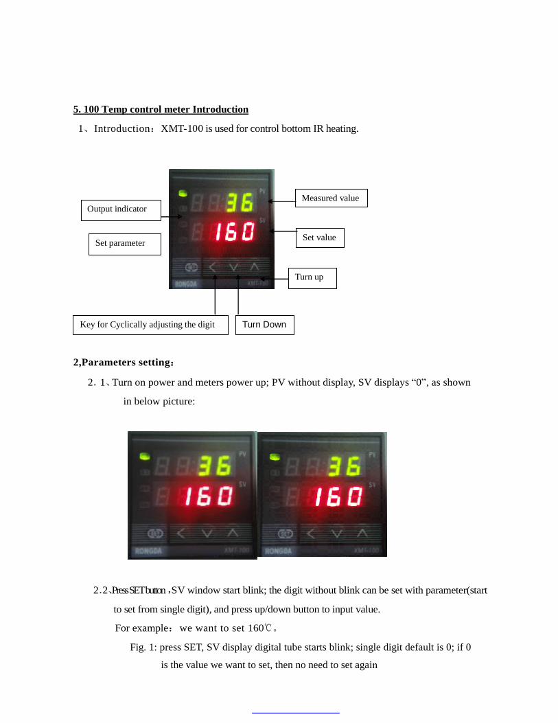
5. 100 Temp control meter Introduction
1、 Introduction:XMT-100 is used for control bottom IR heating.
Ou
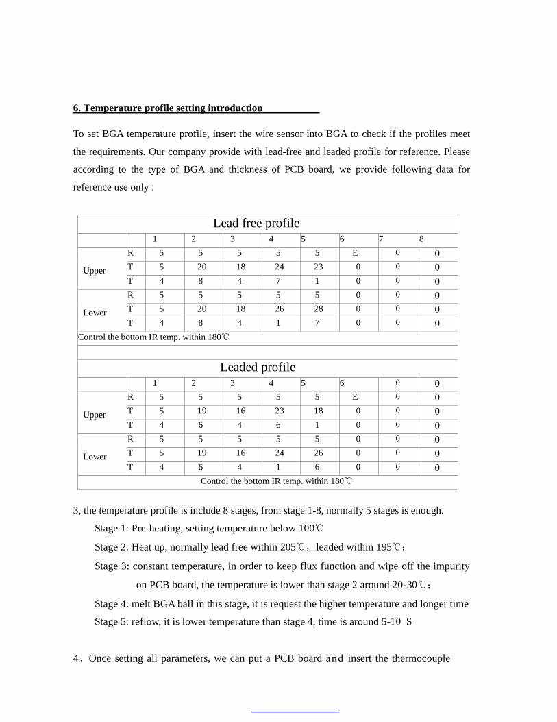
2,Parameters setting:
2.1、Turn on power and meters power up; PV without display, SV displays “0”, as shown
in below picture:
2.2、Press SET button ,SV window start blink; the digit without blink can be set with parameter(start
to set from single digit), and press up/down button to input value.
For example:we want to set 160℃。
Fig. 1: press SET, SV display digital tube starts blink; single digit default is 0; if 0
Output indicator Measured value
Turn Down
Set parameter Set value
Turn up
Key for Cyclically adjusting the digit
is the value we want to set, then no need to set again

Fig. 2: press “cyclically adjust the digit” key to move to ten digit(SV digital tube’s ten digit
doesn’t blink), and then press up key to make it 6
Fig. 3: press “cyclically adjust the digit” key to move to hundred digit (SV digital
tube’s hundred digit doesn’t blink), and then press up key to make it 1
Fig. 4: after finishing setting digits, user has to press SET again
P1: P2:
P3: P4:
Press SET to start
Move to ten digit Press up key to input 6
Press up key to input 1
Move to hundred digit
Press SET again
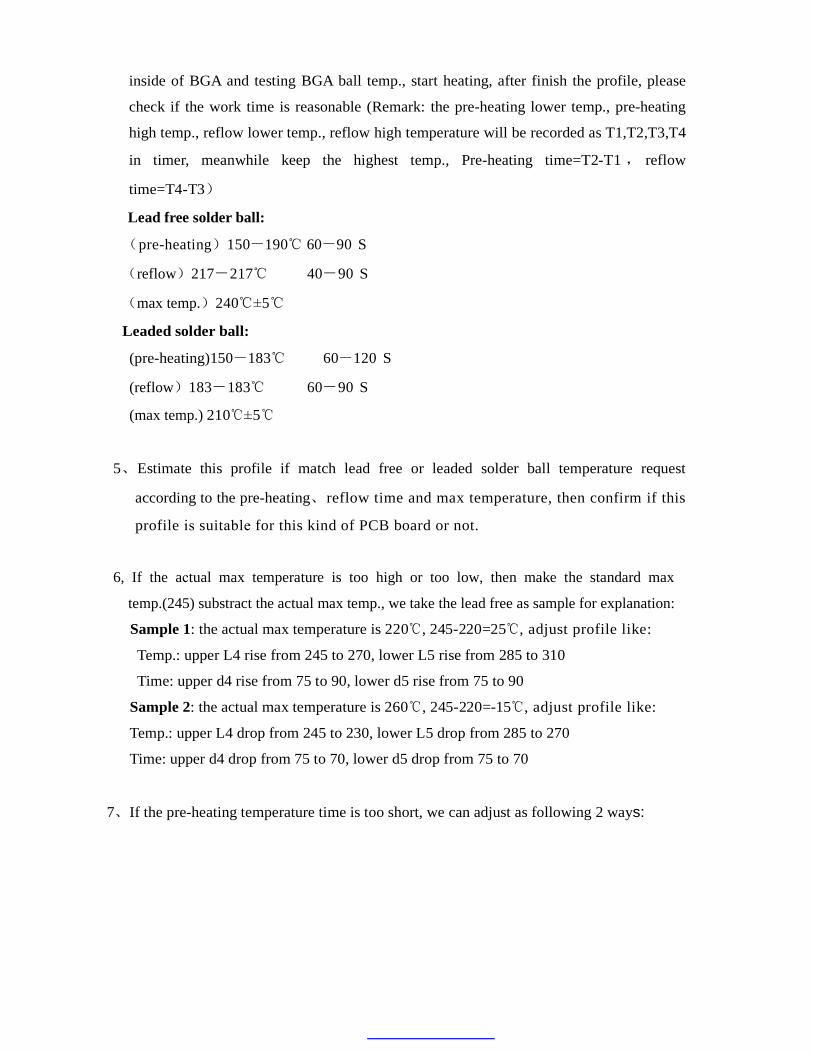
6. Temperature profile setting introduction
To set BGA temperature profile, insert the wire sensor into BGA to check if the profiles meet
the requirements. Our company provide with lead-free and leaded profile for reference. Please
according to the type of BGA and thickness of PCB board, we provide following data for
Lead free profile
1 2 3 4 5
6
7
8 R 5
5
5
5
5
E 0 0 T 5
20
18
24
23
0 0 0
Upper T 4
8
4
7
1
0 0 0 R 5
5
5
5
5
0 0 0 T 5
20
18
26
28
0 0 0
Lower T 4
8
4
1
7
0 0 0 Control the bottom IR temp. within 180℃
Leaded profile
1 2 3 4 5
6
0 0 R 5
5
5
5
5
E 0 0 T 5
19
16
23
18
0 0 0
Upper T 4
6
4
6
1
0 0 0 R 5
5
5
5
5
0 0 0 T 5
19
16
24
26
0 0 0
Lower T 4
6
4
1
6
0 0 0 Control the bottom IR temp. within 180℃
3, the temperature profile is include 8 stages, from stage 1-8, normally 5 stages is enough.
Stage 1: Pre-heating, setting temperature below 100℃
Stage 2: Heat up, normally lead free within 205℃,leaded within 195℃;
Stage 3: constant temperature, in order to keep flux function and wipe off the impurity
on PCB board, the temperature is lower than stage 2 around 20-30℃;
Stage 4: melt BGA ball in this stage, it is request the higher temperature and longer time
Stage 5: reflow, it is lower temperature than stage 4, time is around 5-10 S
reference use only :
4、Once setting all parameters, we can put a PCB board and insert the thermocouple
inside of BGA and testing BGA ball temp., start heating, after finish the profile, please
check if the work time is reasonable (Remark: the pre-heating lower temp., pre-heating
high temp., reflow lower temp., reflow high temperature will be recorded as T1,T2,T3,T4
in timer, meanwhile keep the highest temp., Pre-heating time=T2-T1, reflow
time=T4-T3)
Lead free solder ball:
(pre-heating)150-190℃ 60-90 S
(reflow) 217-217℃ 40-90 S
(max temp.)240℃±5℃
Leaded solder ball:
(pre-heating)150-183℃ 60-120 S
(reflow)183-183℃ 60-90 S
(max temp.) 210℃±5℃
5、Estimate this profile if match lead free or leaded solder ball temperature request
according to the pre-heating、reflow time and max temperature, then confirm if this
temp.(245) substract the actual max temp., we take the lead free as sample for explanation:
Sample 1: the actual max temperature is 220℃, 245-220=25℃, adjust profile like:
Temp.: upper L4 rise from 245 to 270, lower L5 rise from 285 to 310
Time: upper d4 rise from 75 to 90, lower d5 rise from 75 to 90
Sample 2: the actual max temperature is 260℃, 245-220=-15℃, adjust profile like:
Temp.: upper L4 drop from 245 to 230, lower L5 drop from 285 to 270
Time: upper d4 drop from 75 to 70, lower d5 drop from 75 to 70
7、If the pre-heating temperature time is too short, we can adjust as following 2 ways:
profile is suitable for this kind of PCB board or not.
6, If the actual max temperature is too high or too low, then make the standard max
- 1 -
7.1、If the actual temp. is not reach 150℃ after the stage 2(heat up stage)be
finished, so adjust the target temperature of upper and lower profile
accordingly or extend constant temperature time, normally we should make
sure the actual temperature can reach 150℃ after stage 2.
7.2、after stage 2 be finished, if the actual temp. reach 150℃,so extend the
constant temperature stage time( stage 3),the extend time depend on the
pre-heating time situation.
8、if the reflow temperature time too short, how to solve this problem?
You can increase reflow stage constant temperature time, the extend time depend on the
reflow temperature time situation.
9、Testing again, if you still have problems, adjust the parameters as shown above solution .