Embed Size (px)
Citation preview


PAGE iii
Hot Drink Operation and Service Manual
TABLE OF CONTENTS
Warranty ....................................................................................................................... ii
Machine Requirements and Characteristics ......................................................... A-1
Programming ............................................................................................................ B-1
Cleaning and Sanitation .......................................................................................... C-1

PAGE iv
Hot Drink Operation and Service Manual
Notes
PAGE A - 16300021
Hot Drink Operation and Service Manual
MACHINE REQUIREMENTS AND CHARACTERISTICS
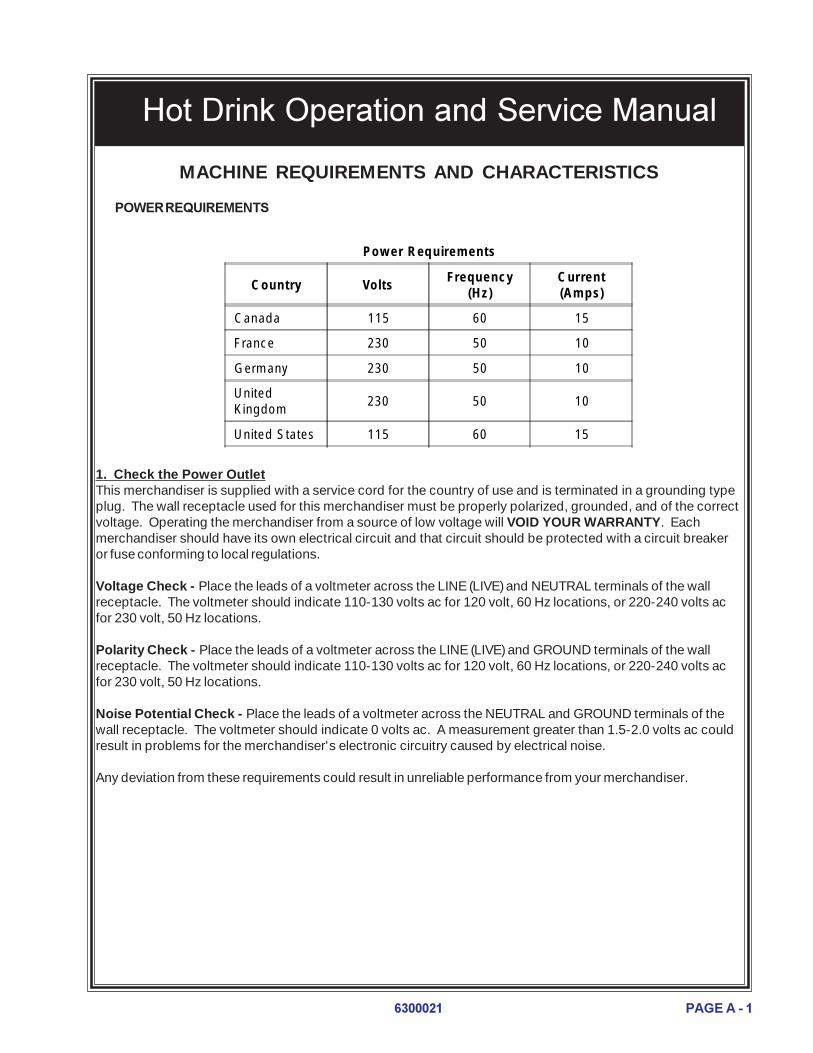
POWER REQUIREMENTS
Power Requirements
Country VoltsFrequency
(Hz)Current(Amps)
Canada 115 60 15
France 230 50 10
Germany 230 50 10
UnitedKingdom
230 50 10
United States 115 60 15
1. Check the Power OutletThis merchandiser is supplied with a service cord for the country of use and is terminated in a grounding typeplug. The wall receptacle used for this merchandiser must be properly polarized, grounded, and of the correctvoltage. Operating the merchandiser from a source of low voltage will VOID YOUR WARRANTY. Eachmerchandiser should have its own electrical circuit and that circuit should be protected with a circuit breakeror fuse conforming to local regulations.
Voltage Check - Place the leads of a voltmeter across the LINE (LIVE) and NEUTRAL terminals of the wallreceptacle. The voltmeter should indicate 110-130 volts ac for 120 volt, 60 Hz locations, or 220-240 volts acfor 230 volt, 50 Hz locations.
Polarity Check - Place the leads of a voltmeter across the LINE (LIVE) and GROUND terminals of the wallreceptacle. The voltmeter should indicate 110-130 volts ac for 120 volt, 60 Hz locations, or 220-240 volts acfor 230 volt, 50 Hz locations.
Noise Potential Check - Place the leads of a voltmeter across the NEUTRAL and GROUND terminals of thewall receptacle. The voltmeter should indicate 0 volts ac. A measurement greater than 1.5-2.0 volts ac couldresult in problems for the merchandiser's electronic circuitry caused by electrical noise.
Any deviation from these requirements could result in unreliable performance from your merchandiser.
PAGE A - 2 6300021
Hot Drink Operation and Service Manual
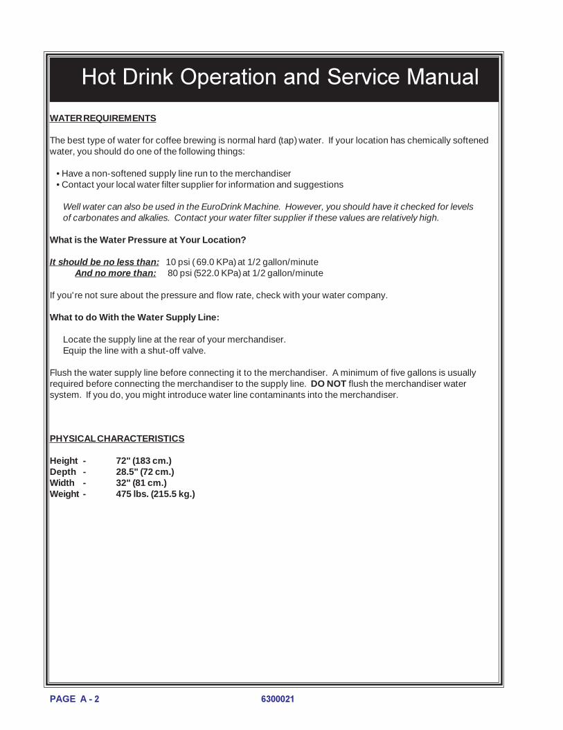
WATER REQUIREMENTS
The best type of water for coffee brewing is normal hard (tap) water. If your location has chemically softenedwater, you should do one of the following things:
•Have a non-softened supply line run to the merchandiser•Contact your local water filter supplier for information and suggestions
Well water can also be used in the EuroDrink Machine. However, you should have it checked for levelsof carbonates and alkalies. Contact your water filter supplier if these values are relatively high.
What is the Water Pressure at Your Location?
It should be no less than: 10 psi ( 69.0 KPa) at 1/2 gallon/minuteAnd no more than: 80 psi (522.0 KPa) at 1/2 gallon/minute
If you're not sure about the pressure and flow rate, check with your water company.
What to do With the Water Supply Line:
Locate the supply line at the rear of your merchandiser.Equip the line with a shut-off valve.
Flush the water supply line before connecting it to the merchandiser. A minimum of five gallons is usuallyrequired before connecting the merchandiser to the supply line. DO NOT flush the merchandiser watersystem. If you do, you might introduce water line contaminants into the merchandiser.
PHYSICAL CHARACTERISTICS
Height - 72" (183 cm.)Depth - 28.5" (72 cm.)Width - 32" (81 cm.)Weight - 475 lbs. (215.5 kg.)

PAGE A - 36300021
Hot Drink Operation and Service Manual
LED1 LED2
MAIN CONTROLLERPCB ASSEMBLY
POWER ON(LED 1)
FLASHINGHEARTBEAT
(LED 2)
Controller CardDisplay
Main Controller Card Display. This display consists of two light emitting diodes (LED) mounted on thecontroller card.
POWER ON When lit, this red LED indicates electrical power is applied to the controller card.
HEARTBEAT When flashing, this red LED indicates that the controller card is active and the soft-ware is operating.
NORMAL CONDITIONS:When the merchandiser is operating normally, you should see a steady red POWER ON indicatorand a flashing red HEARTBEAT indicator. Refer to the maintenance manual if any other conditionexists.

PAGE A - 4 6300021
Hot Drink Operation and Service Manual
From a safety standpoint it is very important that the merchandiser be level. A level merchandiser isless likely to tip over and cause personal injury. Level the merchandiser by moving the leg levelersin or out for proper adjustment. Pliers or channel locks may be required to loosen the leg levelers.Level the merchandiser from the right to left and from front to back using a spirit level. When themerchandiser is part of a bank of machines, it should be leveled in reference to the other machines.
CautionHave an assistant hold the merchandiserwhile you adjust the leg levelers.
COIN MECHANISMSetting the Quarter SwitchIf your coin mechanism is not a MARS TRC6000, skip this procedure and begin loadingthe coin mechanism. If your coin mecha-nism is a MARS TRC 6000, flip down thetop front of the mechanism and set thequarter switch as shown on the drawing tothe right. Make sure switch #2 is in thedown or "off" position.
Loading the Coin Mechanism1. Open the cabinet door and the mon-
etary cabinet2. Insert coins into their respective tubes.
Make sure each tube is full.3. Inspect the tubes for shingled coins and
correct if necessary.
BILL VALIDATOR
Emptying the Stacker1. Push up on the magazine latch to
release the housing2. Open the magazine by pulling it down.3. Remove the bills and close the maga-
zine. Make sure it is secure.
LEVELING THE MERCHANDISER
ON
1 2 3 4
HIGH QUARTERSWITCH
SETTING THE QUARTER SWITCH
EMPTYING THE BILL STACKER

PAGE A - 56300021
Hot Drink Operation and Service Manual
WATER FILTER CARTRIDGE
If your merchandiser has a water filter option, it cannot be operated without a properly installed water filtercartridge.
NoteCheck the water filter installation record. There is a place to write the vend number on the cartridge. Thefilter is normally effective for approximately 26,000 7 oz. vends, 22,000 8 oz. vends, 20,000 9 oz. vends,or 15,000 12 oz. vends. Local conditions may require more frequent replacement.
Removal1. Turn the main power switch to the off position.2. Flip the lock lever UP (view A). The lock lever on the water filter head is used to open and close the
water inlet to the merchandiser.3. Rotate the locking collar to the left about 60 degrees until it drops to the filter receiving position.4. Rotate the filter to the left until it drops free of the locking collar.
Installation1. Align the raised rib near the top of the cartridge with the ribless portion of the locking collar (view B).2. Push the cartridge up into the filter head (view B).3. Rotate the cartridge to the right until the lock lever engages the locking collar (view C).4. Rotate the locking collar to the right until it moves up into the locking position (view D).5. Push the lock lever DOWN (view E).
NoteDo not flush the water filter cartridge.
VIEW BVIEW B VIEW CVIEW C VIEW DVIEW D VIEW EVIEW E
VIEW AVIEW A
WATER
INLET
VALVE
WATER
INLET
VALVE
LOCK LEVERLOCK LEVER
WATER FILTERWATER FILTER 626P0010
PAGE A - 6 6300021
Hot Drink Operation and Service Manual
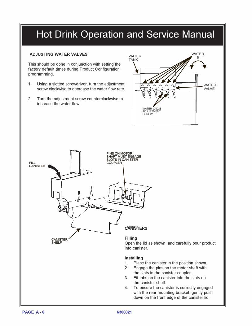
ADJUSTING WATER VALVES
This should be done in conjunction with setting thefactory default times during Product Configurationprogramming.
1. Using a slotted screwdriver, turn the adjustmentscrew clockwise to decrease the water flow rate.
2. Turn the adjustment screw counterclockwise toincrease the water flow.
626P0017
FILL
CANISTER
FILL
CANISTER
CANISTER
SHELF
CANISTER
SHELF
PINS ON MOTOR
SHAFT MUST ENGAGE
SLOTS IN CANISTER
COUPLER
PINS ON MOTOR
SHAFT MUST ENGAGE
SLOTS IN CANISTER
COUPLER
WATER VALVEADJUSTMENTSCREW
WATERVALVE
+ -
123456
WATER6WATER
TANK
CANISTERS
FillingOpen the lid as shown, and carefully pour productinto canister.
Installing1. Place the canister in the position shown.2. Engage the pins on the motor shaft with
the slots in the canister coupler.3. Fit tabs on the canister into the slots on
the canister shelf.4. To ensure the canister is correctly engaged
with the rear mounting bracket, gently pushdown on the front edge of the canister lid.

PAGE A - 76300021
Hot Drink Operation and Service Manual
CUP MECHANISM
Loading
1. Support the cup mechanism in the upright position.2. Push the latch forward to release the cup mechanism. Continue to support the mechanism while you
lower it into the loading position.3. Remove the turret cover.4. Open the bottom of the wrapper on a stack of cups.5. Insert the wrapped cups into the turret and pull the wrapper out.6. Replace the turret cover after the turret has been loaded7. Make sure the cup mechanism is locked into the upright position.
DOOR
CUPMECHANISM
TOP VIEW
1B 1A
CUP STACK ROTATION
LOAD CUPS
HERE
CABINETDOOR
RETAININGSTRAP
LID
CUP MECHMOUNTINGBRACKET
LATCH
CUP TURRET
CUPS
TOP VIEW
Cups1. Use only cups which have been designated for use in a hot beverage vending machine.2. Check to insure that the cup size you are loading agrees with the cup size selected
during programming3. Make sure you observe proper hygiene. Touch only
the wrapper and not the cups.4. Do not fill cups above the level marked on the
outside of the cup turrets or above the "Fill Line"label inside each turret.
5. Check to make sure the cups you are loading arethe same size and brand of those hot drink cupscurrently in the turret. Do not intermix.

PAGE A - 8 6300021
Hot Drink Operation and Service Manual
Adjustment
1. Place seven cups in the cup ring2. Observe the clearance as shown in view B.3. To adjust, first loosen the adjustment arm screw (view A).4. Next, move the adjustment arm until the correct clearance is achieved.5. Finally, hold the adjustment arm in place and tighten the adjustment arm screw.

PAGE A - 96300021
Hot Drink Operation and Service Manual
PRESSUREGAUGE
INCREASEPRESSUREADJUSTCONTROL
INGREDIENTS SHELF
MONETARYPANEL
Pressure Adjust Control. This control determines the system pressure provided by the air compressor.Adjust the pressure as follows:a. With the compressor running, pinch the brewer inlet air tube.b. Adjust the pressure to read 10 - 12 psi on the gauge.
This will produce a pressure of 3 - 6 psi using regular coffee and 8¼ oz cups. No further air pressureadjustments should be necessary.
Pressure Gauge. This indicator shows the amount of air pressure in the system.
LOADING OPTIONAL FILTER PAPER
1. Turn the main power switch to the OFF posi-tion.
2. Remove the cup station and grounds bucket.3. Remove the paper holder cover by turning the
fastener a quarter turn to the left.4. Insert a roll of paper into the paper holder.
Route the free end of the paper to the breweras shown.
5. Replace the cover on the paper holder. Se-cure it by turning the fastener a quarter turn tothe right.
6. Feed paper over swing arm assembly andunderneath pinion gear shaft.
PAPERHOLDER PAPER
ROLL
COVER
FASTENER
TO BREWER

PAGE A - 10 6300021
Hot Drink Operation and Service Manual
LIP OF PAPER MECHANISM HOUSING
PAPER MECHANISM HOUSINGSWING ARM ASSEMBLY
PAPERGUIDES
PINION GEAR SHAFT
BASKET HOUSINGASSEMBLY
SWING ARMASSEMBLY
LIP OF PAPER MECHANISM HOUSING
PAPER MECHANISM HOUSING
7. Feed paper through the paperguides.
8. Raise the basket housing assem-bly and feed paper over the lip ofthe paper mechanism housing.
9. Reach underneath the brewerbetween the paper mechanismhousing and basket housingassembly and push paper into thetop of the paper mechanismhousing between paper rollers.
NOTEIt may be necessary to reachunderneath the brewer betweenthe paper mechanism housingand swing arm assembly to pushpaper over the lip of the papermechanism housing.
PAPERROLLER
BASKET HOUSING ASSEMBLY
PAPER MECHANISM HOUSING
10. Reach underneath the brewer and pullpaper roller to the right.
11. Pull paper down between the paper rollers.12. Release the paper roller.
13. Place the main power switch in the ON posi-tion.
14. Enter BREWER TEST mode (see SERVICE)and cycle the brewer to observe that paperfeeds properly.
15. Replace the cup station and grounds bucket.

PAGE A - 116300021
Hot Drink Operation and Service Manual
HOT WATER TANK CLEANING PROCEDURE
Some smell and/or taste problems may occur in new machines. Follow this procedure to clean the hot watertank if you experience problems:
1. If the machine is in service, remove power from the machine.2. Dissolve 1 tablespoon of common baking soda in a cup of water.
WARNINGThe water tank may be HOT. Be careful when working on the tank.
3. Loosen or remove the hot water tank lid and pour the baking soda solution into the tank.4. Apply power to the machine.5. If the tank is not full, fill it.6. Allow the tank to reach its operating temperature.7. Leave the solution in the tank for AT LEAST ½ hour. If possible, leave the solution in the tank for 1
hour.8. Drain the tank.9. Refill the tank, then drain again.10. Refill the tank and put the machine back into service.

PAGE A - 12 6300021
Hot Drink Operation and Service Manual
Notes

Hot Drink Operation and Service Manual
PAGE B - 16300021
PROGRAMMING
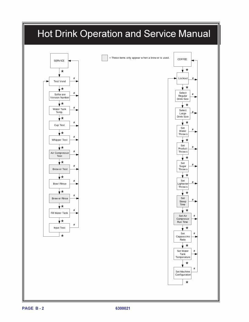
The diagram on these pages is a map of the programming functions in your merchandiser. These functions will be described ingreater detail, but this will help you get around once you are familiar with how programming works. The symbols * and #represent special keys that move you around inside the programming modes, and from one mode to another. As you can see onthe diagram, these symbols show up in the pathways in and around the modes.
Standby Message
DATA
PAY OUT(NDQ = 123)
PRICE
FAULTS
SERVICE(SEE NEXT PAGE FOR DETAILS)
SETUP
COFFEE (SEE NEXT PAGE FOR DETAILS)
Paid Sales
Paid Vends
Unpaid Sales
Unpaid Vends
Price Indiv idual Selections
FirstMachine Fault
Display
Second Machine Fault
Display
LastMachine Fault
Display
Free Vend
On/Of f
Validator Options
Change Options
SelectDisplay
Language
*#
*
#
#
#
#
# # #
*
# #
#
*
= These items do not appear when an EXEC coin mech is used.
Select Coin Mech
#
* * * * *Total Test
Vends
# # # # #
Note:Pressing and holding # will return to the standby
message from anywhere.
#
#
* * *
* * * * *
#
#
TIME OF DAY
#
#
DateActiv ate
Freev end Periods
First Freev end
Period Start Time
First Freev end
Period Stop Time
# # # #
*****
Low Change Message
Declining Balance
* *
# #
Mug Vends
#
View or Change
Machine ID
Last Freev end
Period Start Time
Last Freev end
Period Stop Time
#
*#
*
Up to 4 f reev end periods are supported.
Select Card
Options
#
*
First Freev end
Period Selections
#
*Last
Freev end Period
Selections
*
Hot Drink Operation and Service Manual
PAGE B - 2 6300021
Softw are Version Number
Water Tank Temp.
Cup Test
Whipper Test
Air Compressor Test
Brew er Test
Bow l Rinse
*
Fill Water Tank
SERVICE COFFEE
Lockout
Select Regular
Drink Size
Set Water Throw s
Set Product Throw s
Set Sugar
Throw s
Set Lightener Throw s
Set Cappuccino
Ratio
Set Machine Conf iguration
Brew er Rinse
Input Test
#
#
#
#
#
SetSteep Time
Set Air Compresor Run Time
Set Water Tank
Temperature
*
#
#
#
#
#
#
#
#
#
#
= These items only appear w hen a brew er is used.
#Select Large
Drink Size
Test Vend
#
#
#
#
#
#
*
*
*
*
*
*
*
*
*
*
*
#
*
*
*
*
*
*
*
*
*
*
*
*

Hot Drink Operation and Service Manual
PAGE B - 36300021
THE KEYPAD
During vending, customers use the keypad to makeselections. When you pull the door switch to the ONposition, the keypad becomes your programminginput device. For reference, we will show the keypadon all the pages.
DATA
View several types of sales data:NOTE
All data is not resettable.
1. Pull out the door switch button to the ON position.
2. Press # until the display shows DATA.
3. If you have the DEX option, press to transfer data into your DEX device.
4. Press . The display shows **$ .XX. This is the dollar and cents amount of paid sales.
5. Press . The display shows ** XX. This is the count of paid vends.
6. Press . The display shows _0$ .XX. This is the dollar and cents amount of unpaid "sales". (Does
not display if the total is zero.)
7. Press . The display shows _0 XX. This is the total count of unpaid vends. (Does not display if the
total is zero.)
8. Press . The display shows MUG XX. This is the count of mug vends. (Does not display if the total
is zero.)
9. Press . The display shows TST XX. This is the total count of test vends. (Does not display if the
total is zero.)
10. Press . The display shows ID XXXXXX. This is the machine ID number. Use - and -
to enter a unique identifier for the machine.
11. Press to return to step 4, or # to exit.
SPECIAL PROGRAMMING KEYS
# Press this key to move from one function to another.
From within a function, press once to return to the beginning of the function; pressand hold to return to the standby message.
This key moves you around inside of a function.
This key allows you to switch between two or more choices.
This is the "action" key. It will start tests, fill the water tank, etc.

Hot Drink Operation and Service Manual
PAGE B - 4 6300021
PAY OUT (Does not apply to machines with EXEC coin mechanisms.)
Pay out coins:1. Pull out the door switch button to the ON position.2. Press # until the display shows
NDQ = 1.2.3 (dumb mech). This is telling you that pressing pays out nickels, pressing pays
out dimes, and pressing pays out quarters.
OR
PAY = 1.2.3 (MDB mech). This is telling you that pressing pays out from tube 1 (nickels), pressing
pays out from tube 2 (dimes), and pressing pays out from tube 3 (quarters).
3. Press the appropriate key once to pay out one coin.4. Press and hold the appropriate key to pay out coins continuously.
5. Press and hold # to return to the standby message.
PRICE
0A .25
Selection size:blank = regular drink size
1 = large drink size
Selection letter
Selection priceThe price display:
Set prices for all the selections in your merchandiser:
1. Pull out the door switch button to the ON position.
2. Press # until the display shows PRICE.
3. Press , and the display shows A .XX. "XX" is the price for the regular size A selection.
4. Press until the selection you want to price is displayed.
ORPress the letter of the selection you want to price, then press the selection size, and it will be displayedimmediately.
5. Enter a new price with the number keys.6. Repeat steps 4 and 5 until you have priced all the selections.
OR
7. Press # to return to the PRICE display, or hold # to exit.

Hot Drink Operation and Service Manual
PAGE B - 56300021
FAULTS
Display all the active faults on your merchandiser:
1. Pull out the door switch button to the ON position.
2. Press # until the display shows FAULTS.
3. Press to see the list of faults:
NO ERRORS There are no faults on the machine.
KEYPAD XY Key(s) �X� and �Y� are stuck.
ROM ERROR Error with ROM.
RAM ERROR RAM is not initialized or is not compatible with the currently loaded soft-ware. If this message appears, initialize your RAM by performing thefollowing procedure:NOTE: Initializing RAM will erase all your data and drink setings. Besure you have written this information down before continuing.
Press AND HOLD . You will see CLEARING in the display. Continue
holding until two beeps are heard and the display shows FINISHED.
CONFIG ERR Error with machine configuration.
RING.MTR The cup ring is jammed.
MOT� R 12 Cup turret motor 1 or 2 is jammed.
NO CUPS 1 Out of cups.
WASTE PAIL The waste pail is full.
LOW WATER The water level in the tank is low.
COLD TANK Water is too cold to vend.
NO SENSOR Illegal temperature reading.
TANK ERR A fault occurred in the inlet system.
WHIP 123 Whipper motor failure (motor 1, 2, or 3).
BREWER JAM The brewer is jammed.
MECH ERR Problem with the coin mechanism.
CARD. ERR Problem with the card reader.
DBV. ERR Problem with the bill validator.
NONE READY Time of day inhibit is active, or all selections are out ofservice.
CHK PRICE Illegal price is detected.
LOCKS SET All selections are locked.
When the first fault item (if any) repeats, you have seen all the faults.
When active faults exist, pulling the door switch will automatically display FAULTS.
4. Press to see more faults or # to exit.

Hot Drink Operation and Service Manual
PAGE B - 6 6300021
SERVICE
View machine status and test certain functions:
1. Pull out the door switch button to the ON position.
2. Press # until the display shows SERVICE.
3. Press . The display shows TEST .00. You can test vend selections. Insert
coins and bills into the merchandiser, and the amount you inserted is displayed.
4. Press . The display shows the software version number.
5. Press . The display shows the water tank temperature. Temperature is
displayed in either degrees Fahrenheit (F) or Celsius (C), depending upon whatwas set in the COFFEE mode.
6. Press . The display shows CUP TEST. To drop a cup, press .
7. Press . The display shows WHIP TEST. To test the whipper(s), do one of the following:
a. Press the selection letter that uses the whipper you want to test. For example, pressing will test
whipper #1. (The display shows WHIP 1.)b. Press the number of the whipper. The display shows the whipper number you pressed. (If you press a
whipper number that does not exist, nothing happens.)
8. Press . The display shows AIR TEST. To test the air compressor, press .
9. Press . The display shows BREW TEST. Press , and each brewer position is displayed:
WARNINGKeep away from the brewer mechanism while it is operating. Coming into contact with movingparts could injure you.
a. BREW'R BREW - The brewer is in the BREW position.
b. BREW'R FLIP - The brewer is in the FLIP position.
c. BREW'R HOME - The brewer is in the HOME position.
10. Press . The display shows BOWL RINSE. To rinse the bowls, press . Hot water is delivered to
the mixing bowl(s), and the display shows RINSING until the cycle is complete.
11. Press . The display shows BREW RINSE. To rinse the brewer, press . The brewer cycles and the
display shows CLEANING until the cycle is complete.
12. Press . The display shows TANK.FILL.
Hot Drink Operation and Service Manual
PAGE B - 76300021
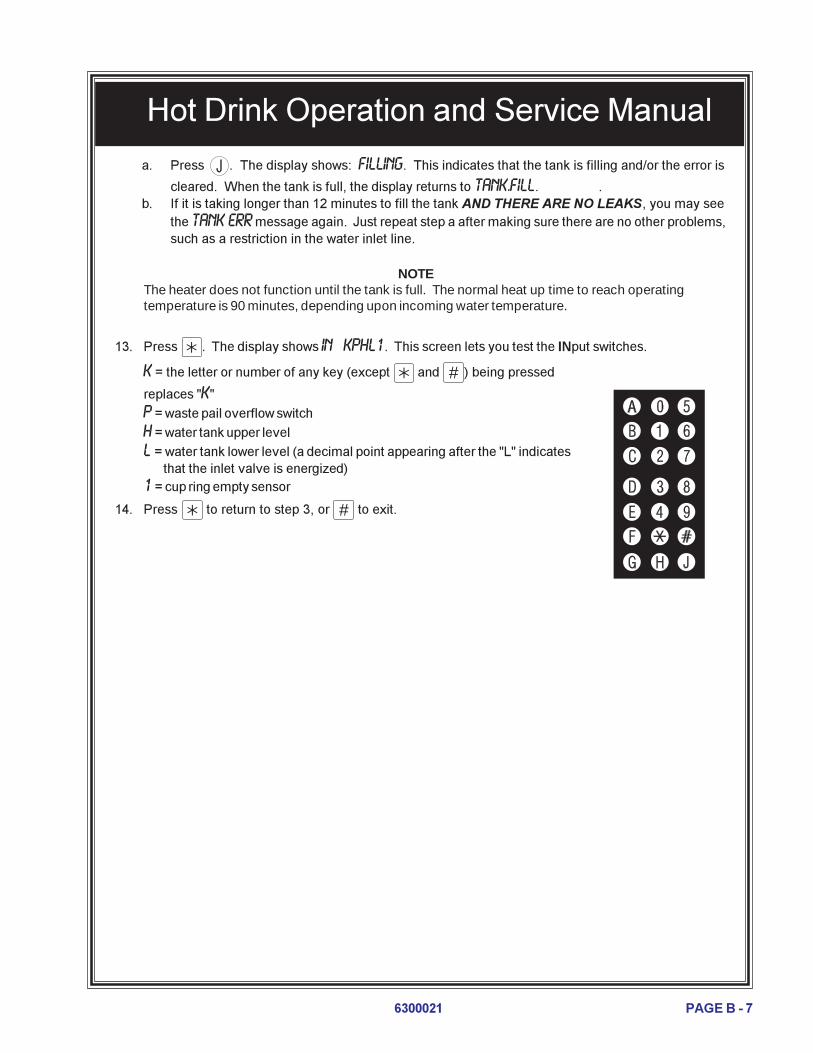
a. Press . The display shows: FILLING. This indicates that the tank is filling and/or the error is
cleared. When the tank is full, the display returns to TANK.FILL. .b. If it is taking longer than 12 minutes to fill the tank AND THERE ARE NO LEAKS, you may see
the TANK ERR message again. Just repeat step a after making sure there are no other problems,such as a restriction in the water inlet line.
NOTEThe heater does not function until the tank is full. The normal heat up time to reach operatingtemperature is 90 minutes, depending upon incoming water temperature.
13. Press . The display shows IN KPHL1. This screen lets you test the INput switches.
K = the letter or number of any key (except and # ) being pressed
replaces "K"
P = waste pail overflow switch
H = water tank upper level
L = water tank lower level (a decimal point appearing after the "L" indicates that the inlet valve is energized)1 = cup ring empty sensor
14. Press to return to step 3, or # to exit.

Hot Drink Operation and Service Manual
PAGE B - 8 6300021
SETUPConfigure various machine functions:
1. Pull out the door switch button to the ON position.
2. Press # until the display shows SETUP.
3. Press . The display shows either FREE ALL or FREE OFF. When FREE ALL is displayed, all
selections are free. Press to switch between ALL and OFF.
4. Press . The display shows either DUMB MECH, MDB MECH, EXEC MECH , or NO MECH. Press to
switch between these coin mech choices.
5. Press . The display shows the bill validator choices. Press to switch between the choices:
SER. 1.2.5.10.20 = A serial validator is installed. Press , , 5 , 6 , or (respectively) to
display the bill (s) which will be accepted.OR
MDB. 1.2.5.10.20 = An MDB validator is installed. Press , , 5 , 6 , or (respectively) to
display the bill (s) which will be accepted.OR
MDB. <*> = A special MDB validator has been detected after MDB. 1.2.5.10.20 was installed and
interrogated. Press to enter the list of bill(s) or tokens which will be accepted. Press to
scroll through the list and press to turn a particular selection ON or OFF. Press # when you
have completed the list. MDB. <*> will again be displayed.OR
PULSE DBV = A pulse validator is installed.OR
NO DBV = No bill validator installed.
6. Press . The display shows either:
NO CARD = No card reader is installed,DUMB CARD = A dumb (12 pin) card reader is installed,MDB CARD = An MDB card reader is installed.
Press to switch between the choices.
7 Press . The display shows CHANGE X.XX. Change will be given for coins or
bills up to this amount without the customer having to make a selection. Forexample, if 1.00 is displayed, the machine will give the customer change for adollar without requiring a selection. Entering 0.00 means that no change will begiven without a purchase.
8. Press . The display shows: LOW.MSG X.XX. The customer will see USE
EXACT CHANGE in the display when the amount of available change in the coinmechanism falls below the level you set for X.XX. Enter a value with thenumber keys. For example, if LOW.MSG 1.00 is selected, the customer sees the
USE EXACT CHANGE message when less than a dollar's worth of change is in thecoin mechanism.

Hot Drink Operation and Service Manual
PAGE B - 96300021
COFFEE1. Pull out the door switch button to the ON position.
2. Press # until the display shows COFFEE .
3. Press . The display shows LK. ABCDEFG. When letters A through G are
displayed, it indicates the selections that are locked out. An active selection isindicated by a dash (-). Pressing the appropriate letter key(s) switches fromactive to locked out.
NOTEIf your machine is NOT equipped with the International Coffee option, you MUST lock outselection C. Failure to do so will allow "vending" a non-existant selection.
4. In the next two steps, you will set up the two drink sizes. Your machine only supports one cupsize. Therefore, the large size drink selection vends a full cup, while the regular size drink selectionvends a partially filled cup. First, be sure that the cups you have loaded in your machine have thecapacity to hold the large size drink volume. Then follow the two steps below to set up the two drinksizes:
a. Press . The display shows CUP X OZ. Press until the regular size drink volume you
want is displayed.� If you want to load the factory default water and product throw times for your new cup size, press
and hold . The display shows CLEARING, then FINISHED.
b. Press . The display shows CUP.1 X OZ. Press until the large size drink volume you
want is displayed.� If you want to load the factory default water and product throw times for your new cup size, press
and hold . The display shows CLEARING, then FINISHED.
When setting up throw times for water, product, etc., each selection letter shows thetime for a regular size drink and the time for a large drink. The large size drink throwtime is shown with a "1" in front of the selection letter.
9. Press . The display shows either:
DECLINE.ON = More than one vend is allowed, with a declining balance. This means that the customercan choose multiple products until the amount of credit is lower than the lowest priced product in themachine.
OR
DECLINE.OFF = A declining balance is not allowed. Press to switch between these two choices.
10. Press . The display shows either ENGLISH, DEUTSCH, FRANCAIS, ESPANOL, PORTUGUES, SWEDISH or
NEDERLANDS. Press to select the appropriate language for your display.
11. Press to return to step 3, or # to exit.

Hot Drink Operation and Service Manual
PAGE B - 10 6300021
NOTEWhen changing timer setups, you must enter throw times for Caffé Latte (1D) manually. Thesetimes will not be set when loading factory defaults.
5. Press . The display shows WATER. This is the main screen for setting up water throws. If you don't
want to do this, continue to step 6.a. Do one of the following:
Press the letter of the selection whose water throw you want to setOR
Press to go to the A selection, then press until the desired selection is displayed.
b. Example: The display shows WAT. A 5.90. This is the water screen for the A selection. Thenumbers on the right are the throw time for the selection (5.90 seconds in this example).
c. Enter a new throw time, using the number keys.
d. Press test throw the water.
e. Repeat steps a through d to set another selection.
f. Press # to return to the WATER display.
6. Press . The display shows PRODUCT. This is the main screen for setting up dry product throws. If
you don't want to do this, continue to step 7.a. Do one of the following:
Press the letter of the selection whose dry product throw you want to setOR
Press to go to the A selection, then press until the desired selection
is displayed.b. Example: The display shows DRY. A 1.90. This is the water screen for the A
selection. The numbers on the right are the throw time for the selection (1.90seconds in this example).
c. Enter a new throw time, using the number keys.
d. Press test throw the dry product.
e. Repeat steps a through d to set another selection.
f. Press # to return to the PRODUCT display.
CAFFE' LATTE RECIPE(12 oz. recommended)
1. Make sure the machine is configured to use 12 oz.cups.
2. Set up the 1D selection as follows:a. Water: 6.00 seconds = 6 ounces (about 177 ml)b. Coffee: 4.77 seconds = 17 gramsc. Sugar: 0.24 seconds = 2.5 gramsd. Lightener: 2.8 seconds = 5 gramse. Steep time: 12.5 seconds

Hot Drink Operation and Service Manual
PAGE B - 116300021
7. Press . The display shows SUGAR. This is the main screen for setting up sugar throws. If you don't
want to do this, continue to step 8.a. Do one of the following:
Press the letter of the selection whose sugar throw you want to setOR
Press to go to the A selection, then press until the desired selection is displayed.
NOTEThe A and B selections are represented by a star (*). All other selections using sugar arerepresented normally.
b. Example: The display shows SUG. F 1.90. This is the sugar screen for the F selection. Thenumbers on the right are the throw time for the selection (1.90 seconds in this example).
c. Enter a new throw time, using the number keys.
d. Press test throw sugar.
e. Repeat steps a through d to set another selection.
f. Press # to return to the SUGAR display.
8. Press . The display shows LIGHTENER. This is the main screen for setting up lightener throws. If
you don't want to do this, continue to step 9.a. Do one of the following:
Press the letter of the selection whose lightener throw you want to set.OR
Press to go to the A selection, then press until the desired selection is displayed.
NOTEThe A and B selections are represented by a star (*). All other selections using lightener arerepresented normally.
b. Example: The display shows LIT. F .90. This is the lightener screen for the F selection. Thenumbers on the right are the throw time for the selection (0.90 seconds in this example).
c. Enter a new throw time, using the number keys.
d. Press test throw lightener.
e. Repeat steps a through d to set another selection.
f. Press # to return to the LIGHTENER display.
9. Press . The display shows STEEP. This is the main screen for setting up
steep times for brewed selections. If you don't want to do this, continue to step10.a. Do one of the following:
Press the letter of the selection whose steep time you want to set.OR
Press to go to the A selection, then press until the desired selection
is displayed.

Hot Drink Operation and Service Manual
PAGE B - 12 6300021
b. Example: The display shows STP. A+ 2.10. This is the steep timescreen for the large A selection. The numbers on the right are the steeptime for the selection (2.10 seconds in this example).
c. Enter a new steep time, using the number keys.d. Repeat steps a through c to set another selection.
e. Press # to return to the STEEP display.
10. Press . The display shows AIR. This is the main screen for setting up air
compressor running times for brewed selections. If you don't want to do this,continue to step 11.a. Do one of the following:
Press the letter of the selection whose compressor running time you wantto set.
OR
Press to go to the A selection, then press until the desired selection is displayed.
b. Example: The display shows AIR. A 4.10. This is the air compressor time screen for the Aselection. The numbers on the right are the steep time for the selection (4.10 seconds in thisexample).
c. Press J to run the air compressor.d. Repeat steps a through c to set another selection.
e. Press # to return to the AIR display.
11. Press . The display shows RATIO .25. This is the ratio of chocolate to coffee in a cappuccino
drink. In this example, cappuccino uses 25% chocolate.a. Enter a new ratio using the number keys. A ratio between 5 and 50% must be present, or you
can't leave this step.
12. Press . The display shows SET XXX°F. This is the setpoint for the hot water tank (in degrees
Fahrenheit). The hot water tank will maintain this temperature within a few degrees. If you don't wantto change the setpoint, continue to step 13.a. Enter a new setpoint using the number keys. Acceptable range: 149°-205° F (65°-96° C).
b. Press to switch the display between degrees Celsuis and degrees Fahrenheit.
13. Press . The display shows CONF XXXX. The four "X"s represent the configuration code for your
machine. BE SURE THE CODE MATCHES YOUR MACHINE'S ACTUAL CONFIGURATION! Aninvalid configuration will cause an "out of service" condition and a diagnostic message.a. Enter one of the following configurations using the number keys:
If you have a . . . . . . enter this code:Single brew machine ................ 2111Dual brew machine ................... 2121Freeze dry machine .................. 2131
b. Press to return to step 3 or # to exit.

Hot Drink Operation and Service Manual
PAGE B - 136300021
sgnitteStluafeDyrotcaFemiTworhTdnathgieWtcudorPyrD.1DelbaT
noitceleS
pucezisrep)smargni(thgieW___________________________________
pucezisrep)sdnocesni(semitworhT
zo5 zo7 zo8 zo9 zo01 zo21
A eeffocwerbhserF07.506.1
00.802.2
00.905.2
00.0108.2
00.1101.3
00.3156.3
A eeffocyrdezeerF09.053.0
02.105.0
05.106.0
06.156.0
08.107.0
02.209.0
A eeffocyrdezeerfgnortS01.156.0
05.109.0
08.101.1
00.202.1
02.253.1
06.206.1
B facedwerbhserF07.506.1
00.802.2
00.905.2
00.0108.2
00.1101.3
00.3156.3
B facedyrdezeerF09.053.0
02.105.0
05.106.0
06.156.0
08.107.0
02.209.0
B facedyrdezeerfgnortS01.156.0
05.109.0
08.101.1
00.202.1
02.253.1
06.206.1
DeeffocwerbhserF
OSSERPSE07.506.1
00.802.2
00.905.2
00.0108.2
00.1101.3
00.3156.3
DeeffocyrdezeerF
OSSERPSE09.053.0
02.105.0
05.106.0
06.156.0
08.107.0
02.209.0
DeeffocyrdezeerfgnortS
OSSERPSE01.156.0
05.109.0
08.101.1
00.202.1
02.253.1
06.206.1
EeeffocwerbhserF
ONICCUPPAC07.506.1
00.802.2
00.905.2
00.0108.2
00.1101.3
00.3156.3
EeeffocyrdezeerF
ONICCUPPAC09.053.0
02.105.0
05.106.0
06.156.0
08.107.0
02.209.0
EeeffocyrdezeerfgnortS
ONICCUPPAC01.156.0
05.109.0
08.101.1
00.202.1
02.253.1
06.206.1
F aettnatsnI09.007.0
02.100.1
05.152.1
06.103.1
08.106.1
02.258.1
F aettnatsnignortS01.109.0
05.152.1
08.106.1
00.257.1
02.258.1
06.201.2
G etalocohC00.71
08.200.42
00.400.82
56.400.1351.5
00.4356.5
00.1408.6
H puoS03.407.0
00.600.1
00.751.1
06.752.1
05.853.1
02.0156.1
H tcudorPelbuloS0.0154.2
5.3153.3
2.6100.4
8.7153.4
7.9158.4
7.3208.5

Hot Drink Operation and Service Manual
PAGE B - 14 6300021
)deunitnoC(sgnitteStluafeDyrotcaFemiTworhTdnathgieWtcudorPyrD.1DelbaT
noitceleS
*pucezisrep)smargni(thgieW_________________________________
pucezisrep)sdnocesni(semitworhT
zo5 zo7 zo8 zo9 zo01 zo21
I oniccuppacnidesuetalocohC01.355.0
05.457.0
00.558.0
08.500.1
02.650.1
06.703.1
D osserpsenidesuraguS01.253.0
00.354.0
05.355.0
00.406.0
05.456.0
05.508.0
D osserpsenidesuragusartxE00.305.0
53.456.0
08.457.0
53.508.0
52.609.0
02.750.1
E oniccuppacnidesuraguS05.354.0
01.556.0
00.657.0
08.658.0
07.759.0
04.902.1
E oniccuppacnidesuragusartxE06.406.0
08.609.0
07.700.1
05.801.1
04.902.1
00.1154.1
F aetnidesuraguS02.455.0
00.657.0
00.709.0
00.800.1
00.951.1
00.1104.1
F aetnidesuragusartxE05.507.0
00.800.1
00.951.1
00.0152.1
00.1104.1
00.3156.1
F aetnidesurenethgiL02.107.0
05.158.0
00.251.1
05.254.1
00.307.1
00.452.2
F aetnidesurenethgilartxE05.158.0
00.251.1
05.254.1
00.307.1
05.300.2
05.406.2
F aetnidesuetutitsbusraguS06.057.0
58.050.1
00.152.1
01.153.1
03.106.1
05.109.1
F aetnidesuetutitsbusragusartxE08.000.1
01.153.1
03.106.1
04.157.1
06.100.2
09.104.2
-**
raguS02.455.0
00.657.0
00.709.0
00.800.1
00.951.1
00.1104.1
-**
ragusartxE05.507.0
00.800.1
00.951.1
00.0152.1
00.1104.1
00.3156.1
-**
renethgiL02.107.0
05.158.0
00.251.1
05.254.1
00.307.1
00.452.2
-**
renethgilartxE05.158.0
00.251.1
05.254.1
00.307.1
05.300.2
05.406.2
-**
etutitsbusraguS06.057.0
58.050.1
00.152.1
01.153.1
03.106.1
05.109.1
-**
etutitsbusragusartxE08.000.1
01.153.1
03.106.1
04.157.1
06.100.2
09.104.2
DE
osserpsE=oniccuppaC=
oniccuppacrofsemitetalocohC=I
* rotcudorpfoepytehtnopugnidnepedyravlliwworhttnemidnocrotcudorpafothgiewmarglautcaehT.gnitsetyrotcafnopudesabetamixorppaeranevigsthgiewehT.desutnemidnoc
-**
.Fdna,E,D,C/B/Asnoitcelesrofelbaliavaerasremitetutitsbusragusdna,renethgil,ragusetarapeS

Hot D
rink Operation and S
ervice Manual
PA
GE
B - 15
6300021
)puc.zo5(oniccuppaCrofsgnitteStcudorPyrD.2DelbaT
ETALOCOHC EEFFOCYRDEZEERF EEFFOCWERBHSERF
tnecrePthgieW
)mg(gnimiT)ces(
sgnitteSretaWtnecreP
sgnitteSretaWtnecreP
sgnitteSretaW
)lm(emuloV )ces(gnimiT )lm(emuloV )ces(gnimiT )lm(emuloV )ces(gnimiT
)tluafed(51 01.3 04.0 25 05.2 )tluafed(58 75 05.2 )tluafed(58 85 52.2
02 01.4 55.0 45 06.2 08 45 53.2 08 55 51.2
52 00.5 56.0 65 07.2 57 25 52.2 57 35 50.2
03 08.5 57.0 95 58.2 07 94 01.2 07 94 09.1
53 07.6 58.0 16 59.2 56 74 00.2 56 74 08.1
04 06.7 59.0 36 50.3 06 44 58.1 06 54 07.1
54 04.8 50.1 66 02.3 55 14 07.1 55 14 55.1
05 03.9 51.1 86 03.3 05 83 06.1 05 83 54.1
)puc.zo7(oniccuppaCrofsgnitteStcudorPyrD.2DelbaT
ETALOCOHC EEFFOCYRDEZEERF EEFFOCWERBHSERF
tnecrePthgieW
)mg(gnimiT)ces(
sgnitteSretaWtnecreP
sgnitteSretaWtnecreP
sgnitteSretaW
)lm(emuloV )ces(gnimiT )lm(emuloV )ces(gnimiT )lm(emuloV )ces(gnimiT
)tluafed(51 05.4 55.0 65 55.2 )tluafed(58 101 53.4 )tluafed(58 511 00.4
02 08.5 07.0 95 07.2 08 79 02.4 08 011 58.4
52 01.7 58.0 36 09.2 57 29 00.4 57 401 56.3
03 00.8 59.0 56 00.3 07 09 09.3 07 201 06.3
53 03.9 01.1 96 02.3 56 68 57.3 56 69 04.3
04 05.01 52.1 27 53.3 06 18 55.3 06 29 52.3
54 08.11 04.1 67 55.3 55 77 53.3 55 78 50.3
05 01.31 55.1 97 07.3 05 27 51.3 05 38 09.2

Hot D
rink Operation and S
ervice Manual
PA
GE
B - 16
6300021
)puc.zo8(oniccuppaCrofsgnitteStcudorPyrD.2DelbaT
ETALOCOHC EEFFOCYRDEZEERF EEFFOCWERBHSERF
tnecrePthgieW
)mg(gnimiT)ces(
sgnitteSretaWtnecreP
sgnitteSretaWtnecreP
sgnitteSretaW
)lm(emuloV )ces(gnimiT )lm(emuloV )ces(gnimiT )lm(emuloV )ces(gnimiT
)tluafed(51 04.5 56.0 95 08.2 )tluafed(58 231 55.5 )tluafed(58 351 50.5
02 08.6 08.0 26 59.2 08 821 04.5 08 051 59.4
52 00.8 59.0 66 02.3 57 221 51.5 57 441 57.4
03 03.9 01.1 96 04.3 07 711 59.4 07 731 05.4
53 00.11 03.1 37 07.3 56 211 57.4 56 131 03.4
04 07.21 05.1 87 59.3 06 801 06.4 06 421 50.4
54 00.41 56.1 28 02.4 55 501 54.4 55 811 58.3
05 56.51 58.1 58 04.4 05 19 58.3 05 211 56.3
)puc.zo9(oniccuppaCrofsgnitteStcudorPyrD.2DelbaT
ETALOCOHC EEFFOCYRDEZEERF EEFFOCWERBHSERF
tnecrePthgieW
)mg(gnimiT)ces(
sgnitteSretaWtnecreP
sgnitteSretaWtnecreP
sgnitteSretaW
)lm(emuloV )ces(gnimiT )lm(emuloV )ces(gnimiT )lm(emuloV )ces(gnimiT
)tluafed(51 8.5 57.0 06 57.2 )tluafed(58 041 09.5 )tluafed(58 271 06.5
02 6.7 00.1 46 59.2 08 431 56.5 08 551 50.5
52 8.8 51.1 86 51.3 57 031 05.5 57 251 59.4
03 5.01 53.1 27 53.3 07 521 03.5 07 441 07.4
53 3.21 06.1 77 06.3 56 911 50.5 56 831 05.4
04 9.31 08.1 28 58.3 06 311 08.4 06 331 53.4
54 3.51 00.2 58 00.4 55 901 56.4 55 621 01.4
05 1.71 52.2 09 52.4 05 501 05.4 05 421 50.4

Hot D
rink Operation and S
ervice Manual
PA
GE
B - 17
6300021
)puc.zo01(oniccuppaCrofsgnitteStcudorPyrD.2DelbaT
ETALOCOHC EEFFOCYRDEZEERF EEFFOCWERBHSERF
tnecrePthgieW
)mg(gnimiT)ces(
sgnitteSretaWtnecreP
sgnitteSretaWtnecreP
sgnitteSretaW
)lm(emuloV )ces(gnimiT )lm(emuloV )ces(gnimiT )lm(emuloV )ces(gnimiT
)tluafed(51 2.6 08.0 06 08.2 )tluafed(58 661 00.7 )tluafed(58 581 04.6
02 0.8 50.1 56 59.2 08 161 08.6 08 871 51.6
52 8.9 03.1 07 02.3 57 551 55.6 57 271 59.5
03 3.11 05.1 47 04.3 07 051 53.6 07 761 08.5
53 6.31 08.1 08 07.3 56 341 50.6 56 951 05.5
04 3.51 50.2 58 59.3 06 731 08.5 06 251 52.5
54 1.71 03.2 09 02.4 55 131 55.5 55 441 59.4
05 7.81 05.2 49 04.4 05 621 53.5 05 831 57.4
)puc.zo21(oniccuppaCrofsgnitteStcudorPyrD.2DelbaT
ETALOCOHC EEFFOCYRDEZEERF EEFFOCWERBHSERF
tnecrePthgieW
)mg(gnimiT)ces(
sgnitteSretaWtnecreP
sgnitteSretaWtnecreP
sgnitteSretaW
)lm(emuloV )ces(gnimiT )lm(emuloV )ces(gnimiT )lm(emuloV )ces(gnimiT
)tluafed(51 6.7 00.1 46 00.3 )tluafed(58 322 53.9 )tluafed(58 132 51.8
02 8.9 03.1 07 03.3 08 512 00.9 08 322 58.7
52 8.11 55.1 67 06.3 57 802 07.8 57 512 55.7
03 9.31 58.1 28 09.3 07 102 04.8 07 702 52.7
53 1.61 51.2 78 51.4 56 391 50.8 56 102 50.7
04 2.81 54.2 39 54.4 06 581 07.7 06 391 57.6
54 4.02 57.2 99 57.4 55 871 04.7 55 581 54.6
05 3.22 00.3 501 50.5 05 171 01.7 05 871 02.6

Hot Drink Operation and Service Manual
PAGE B - 18 6300021
semuloVdnasemiTtluafeDworhTretaW.1WelbaT
noitceleS
pucezisrep)sdnocesni(emiT_____________________________________________
pucezisrep)lmni(emuloV
zo5 zo7 zo8 zo9 zo01 zo21
A eeffocwerbhserF05.4031
04.6091
05.7022
02.8042
00.9562
00.11513
B facedwerbhserF05.4031
04.6091
05.7022
02.8042
00.9562
00.11513
A eeffocyrdezeerF59.4021
00.7071
52.8002
56.8012
09.9042
06.21503
B facedyrdezeerF59.4021
00.7071
52.8002
56.8012
09.9042
06.21503
D )BF(osserpsE52.2
5602.3
5957.3011
01.4021
05.4331
05.5851
D )DF(osserpsE05.2
0605.3
5851.4001
53.4501
59.4021
03.6351
F aeT59.4021
00.7071
52.8002
56.8012
09.9042
06.21503
G etalocohC58.4001
08.6041
52.8071
57.8081
07.9002
56.11042
H puoS08.4011
59.6061
52.8091
07.8002
00.01032
51.21082
H tcudorPelbuloS58.4001
08.6041
52.8071
57.8081
07.9002
56.11042

Hot Drink Operation and Service Manual
PAGE B - 196300021
TIME OF DAY FEATURES
You can set the clock and calendar features of your machine, as well as set up to four intervals during the daywhen the machine will freevend.
1. Pull out the door switch button to the ON position.
2. Press # until the display shows TIME HH.MM . This is the currently set time, expressed in 24-hour
format.a. If desired, set the time using the number keys. Remember to express the time in 24-hour format:
2:00 pm = 14.00.
3. Press . The display shows the current date: MM/DD YY. For example, 07/25 97 is July 25,
1997.a. If desired, set the month, day, and year using the number keys.
b. To display the date in the European format (DD-MM), press . Note that the European format
uses a dash (-) instead of a slash (/) between the day and month to avoid confusing the twoformats. The display for our example would then be 25 - 07 97.
4. Press . The display shows FREEV 1 - 3 - . This shows the number of active "time-of-day freevend"
periods. In this example, freevend periods 1 and 3 are active.a. To turn on or off the freevend periods, press the corresponding number key (1, 2, 3, or 4).
5. Press . The display shows 1.STRT 10.00. This is the start time of the first freevend period, ex-
pressed in 24-hour time format. This example shows period #1 beginning at 10:00 am.a. If desired, enter a new start time using the number keys.
6. Press . The display shows 1.STOP 14.00. This is the stop time of the first freevend period, ex-
pressed in 24-hour time format. This example shows period #1 ending at 2:00 pm.a. If desired, enter a new stop time using the number keys.
The machine will freevend between the hours of 10:00 am and 2:00 pm every day.
7. Press . The display shows *. ABCDEFG . These are the selections to be free vended during this
period. Pressing or will show selections to be free vended by cup size.
8. Press . The display shows 3.STRT 0.00. This is the start time of freevend period #3. Notice that
the display did not show freevend period #2, since it is inactive (see step 4). This time period and anyothers are treated exactly the same as freevend period #1.
9. Press once to return to step 2, or press and hold # to exit.

Hot Drink Operation and Service Manual
PAGE B - 20 6300021
Notes
Hot Drink Operation and Service Manual
PAGE C - 16300021
CLEANING AND SANITATIONBasics
INTRODUCTION
Anyone who services vending machines must use proper sanitary procedures. Health regulationsrequire that hands be clean when cups, commodities, and food-contact parts are handled or ser-viced.
In addition, Federal and State Health Departments require regular cleaning and sanitizing proceduresfor food contact parts.
The information in this section will explain how to clean and sanitize the merchandiser on a day today basis. A clean and well maintained merchandiser will provide a better product and greater safetyfor your customers.
CLEANING AND SANITIZING -- WHAT�S THE DIFFERENCE?
Clean means �free of visible soil�. In cup vending machine servicing, cleaning is also done tomaintain product quality and to remove food soils, oils, and mineral stains that could affect producttaste, aroma, and appearance.
Sanitizing means the reduction, to safe levels, of the number of disease-causing bacteria that remainon the surface after cleaning. Therefore, cleaning and sanitizing are done in separate steps, asprescribed by health regulations and good industry practice.
When you sanitize you create a healthy and hygienic condition. This leads to wholesome food,which in turn leads to satisfied customers.
HOW DO I SANITIZE?
You can sanitize by using either of these two methods:
Chemicals: The object to be sanitized is treated with a bactericidal compound.
Heat: Raise the temperature of the object high enough to kill bacteria. Water must be at least 170° F.
Hot brew water (if available) is an acceptable sanitizer. When food contact surfaces are washedand/or rinsed, use the hot water available in the machine.
Turn the machine off before using water on the machine.
In either case, the object must be thoroughly clean and completely rinsed in order for the sanitizingprocess to work. Caked-on soils not removed by cleaning, for example, may shield bacteria from asanitizing solution.
SANITIZING IS NO SUBSTITUTE FOR A GOOD CLEANING

Hot Drink Operation and Service Manual
PAGE C - 2 6300021
A GOOD PLACE TO START -- YOUR SANITATION KIT
You need to be sure that each machine is clean, safe, and functioning when you leave it. Inorder to properly do this, you need to have a complete set of the right tools. In addition to thescrewdrivers, pliers, and test equipment necessary to repair a machine, you need to have thetools to clean the machine.
Here is a checklist of the items needed for a good sanitation kit:
Sanitation pailTube and nozzle brushes for food contact surfacesUtility brush for dry spillage around canisters, etc.Disposable towels, wet-strength and lint-free
NOTEWiping with towels can re-contaminate sanitized food-contact parts. Therefore, towelsshould not be used to dry food-contact surfaces. Instead, these parts should be air dried.
Spray detergent, diluted to desired strengthUrn cleaner packets for coffee stains and oilsOdor control chemicals for pailsReplacement parts (if the exchange method is used)Cabinet polish or window cleaner for the outside of the machine
Feel free to add some items to this list. For example, you may want to use a portable vacuumcleaner.

Hot Drink Operation and Service Manual
PAGE C - 36300021
SANITATION PROCEDURES
Refer to the recommended cleaning and sanitation interval table on the final page of this section.For each item, complete the procedure as outlined here.
Food-Contact Parts
NOTEAll food-contact parts must be cleaned AND sanitized. Air dry, do not wipe dry.
Ingredient Canisters - Empty and clean the canisters, augers, and spouts by washing with warmwater and detergent. Sanitize with hot water and allow to air dry completely before returning to thecabinet.
Mixing Bowls - It is important that the mixing bowls be kept clean. The inside of all mixing bowlsshould be rinsed whenever the machine is serviced by performing the "Bowl Rinse" operation asoutlined in the Programming section of this manual.
When required by the cleaning and sanitation schedule at the end of this section or more often ifneeded, remove the mixing bowls from the dry ingredient shelf. Thoroughly clean the mixing bowlsby washing with warm water and detergent. Sanitize with hot water and allow to air dry beforereassembling.
Whipper Cover and Impellers - Remove lids and impellers from the whipper housings, wash the lidsand impeller housing. Sanitize with hot water and allow to air dry before reassembling.
a. Remove the whipper assembly from its mounting and remove the whipper cover.b. Using the impeller removal tool (located in the plastic bag assembly), remove the impeller from
the whipper housing as shown.c. Wash the cover, impeller, and impeller housing. Sanitize with hot water and allow to air dry
before reassembling.d. To reassemble, see detail A. Note that the whipper motor shaft has a flat section. Make sure
this flat section lines up with the "D" shaped hole in the impeller. Press the impeller all the wayonto the whipper motor shaft. Replace the cover.

Hot Drink Operation and Service Manual
PAGE C - 4 6300021
Beverage Discharge Nozzles - Disconnect the beverage dispensing tube from the nozzles. Re-move the nozzles from the mounting bracket. Remove the cap from the nozzle, wash clean andsanitize the nozzles and cap. Refer to the tubing connection diagram for proper routing.
Brewer, Brewer Basket, and Brewer Funnel - The tubing and brewer may be sanitized by perform-ing the BREW RINSE operation as outlined in the programming section. The machine features anautomatic brewer sanitizing feature also described in the programming section.
At times, it may be necessary to wash and sanitize the individual brewer parts. If so, disconnectthe tubes from the brewer manifold. Remove the brewer barrel and manifold assembly from itssupport. Remove the brewer basket and funnel assemblies.
Thoroughly wash all parts using soap and water. Sanitize by rinsing thoroughly with hot water.
Ingredient Chutes - Remove the metal chute(s), wash clean, and sanitize by rinsing with hot water.Air dry before reinstalling.
Condiment Chute Assembly - Remove the condiment chute and cover from the condiment canis-ters. Thoroughly wash all parts using soap and water. Sanitize by rinsing thoroughly with hotwater.
Non Food-Contact Parts
Brewer Mechanism Cleaning - Remove the brewer mechanism from its mounting and rinse withthe spray hose.
Cup Delivery Compartment - Remove the compartment from the merchandiser. Wash clean andrinse with hot water.
Exhaust Fan Filter - Remove the filter from its housing. Wash with soap and water, rinse, wringdry, and replace into housing.
Grounds Pail - Empty and rinse the grounds pail. Reline the pail with a clean plastic liner.
Waste Pail - Empty, wash, and rinse with hot water. Sprinkle detergent powder in the bottom ofthe pail to help control odors.
Ingredient Rinse Tray - Remove product canisters. Wash and rinse with hot water. Allow to airdry.

Hot Drink Operation and Service Manual
PAGE C - 56300021
OVERALL CLEANING
Inspect your merchandiser both inside and out. Be sure to check corners and all less visible parts ofthe merchandiser.
Clean where needed.
Allow the inside of the cabinet to dry thoroughly before you close the door.
National Vendors recommends using the following supplies:
A commercial glass cleaner on the glass in the cabinet door.
A mild detergent and warm water on the cabinet, brewer, and other NON ELECTRICAL components.
CAUTION!The plastic parts in your merchandiser should be cleaned with mild detergent and warmwater. The use of other cleaning agents may damage the material, and should be avoided.
Do not get electrical connections or electrical components wet.
Do not use wax or lubricants which contain silicone on or in the merchandidser. Silicone orsilicone vapors can cause electrical failures.
Set the main switch to OFF before cleaning or servicing the merchandiser.
Be sure the area is well ventilated and no open flames are present before using any aerosolspray.
Use protective glasses or a protective shield if an air hose is used for cleaning or drying.

Hot Drink Operation and Service Manual
PAGE C - 6 6300021
TOCONDIMENT
BOWL
TOSOUPBOWL
TOCHOCOLATE
BOWL TOHOT WATER
VALVE
DISPENSINGNOZZLESUPPORT
TUBE ROUTING DIAGRAM
PREVENTIVE MAINTENANCE CLEANING
Periodically, you should visually inspect your merchandiser's hot water tank for excessive limeand scale buildup. This buildup on the tank walls, water valves, and heater element will varydramatically, depending upon water quality. You should develop a cleaning and delimingschedule based on the apparent local water quality.
NOTETo aid in removing scale from your merchandiser, National Vendors has a service kitavailable: part number 6400080. In addition, if your machine has the Everpure waterinlet filter system option, a second kit (part number 6400086) is also available.

Hot Drink Operation and Service Manual
PAGE C - 76300021
SLAVRETNINOITATINASDNAGNINAELCDEDNEMMOCER SLAVRETNINOITATINASDNAGNINAELCDEDNEMMOCER SLAVRETNINOITATINASDNAGNINAELCDEDNEMMOCER SLAVRETNINOITATINASDNAGNINAELCDEDNEMMOCER SLAVRETNINOITATINASDNAGNINAELCDEDNEMMOCER
METI YLIAD YLKEEW YLHTNOM YLRETRAUQ YLLAUNNA-IMES
sretsinaCtneidergnI S/C
slwoBgnixiM R S/C
srellepmIdnasdiLreppihW R S/C
selzzoNegrahcsiDegareveB S/C
tnemtrapmoCyrevileDpuC C
retliFnaFtsuahxE C
liaPetsaW C
lennuF,teksaB,rewerB C S
setuhCtneidergnI C S
msinahceMrewerB C
liaPsdnuorG C
lavretnisihttaezitinaS=S esniR=R lavretnisihttanaelC=C

Hot Drink Operation and Service Manual
PAGE C - 8 6300021
Notes

Hot Drink Operation and Service Manual
Appendix A - 16300021
APPENDIX A. THE INFRARED MUG/CUP SENSOR
The infrared mug/cup sensor can sense the presence of a mug or cup without using moving parts.
Indicator light
The sensor is equipped with an indicator light. This light will help you get the best results from the infraredmug/cup sensor.
Under these conditions:
· Machine door open· Cup station in place· No cup in the station
The indicator light should be off. If it is on, it is indicating improper cup station alignment or excessivesensor sensitivity.
Under these conditions:
· Machine door closed· Cup station in place· No cup in the station
Press any letter on the selection switch panel, for example, A. Only the letter A should be showing in themessage display. If “A MUG” is displayed, it indicates one or more of the following:
· Improper cup station alignment· Excessive sensitivity (the sensor is sensing the delivery door)· Cup station lens is not clean
Cleaning
As indicated in the Sanitation section, you should remove the cup station to clean it. Pay particularattention to the dark colored infrared mug/cup sensor lens, which is part of the cup station. If it is notthoroughly cleaned, the sensor will not work properly.
CAUTIONDo not get liquid inside the sensor unit.
Cleaning the infrared mug/cup sensor unit itself is not usually necessary. If it does require cleaning, justwipe it with a damp cloth.

Hot Drink Operation and Service Manual
Appendix A - 2 6300021
1. Remove the plastic cap in the rear of thesensing unit, exposing the potentiometeradjusting screw, as shown.
2. Turn the screw clockwise to increasesensitivity of cup detection, or counter-clockwise to decrease sensitivity.
3. Calibrate the sensor:CAUTION
Do not adjust sensitivity too far,or unreliable sensing could result.
INDICATORLIGHT
ADJUSTING SCREW PLASTIC CAPSHOWN REMOVED
VIEWING REAR OF SENSOR ASSEMBLY
PLASTIC CAP
INDICATOR LIGHT
CUPDEFLECTORS
CUP
a. Using a piece of WHITE poster board or heavy cardboard, make a 5" x 5 5/8" target.
NOTEIT IS VERY IMPORTANT THAT THIS MATERIAL BE WHITE.
b. Place the target in the cup station justbeyond the cup deflectors. The targetshould be standing vertically; not tiltedforward or backward.
c. With the target in place, turn the adjustingscrew clockwise very slowly until theindicator just turns ON.
d. Turn the adjusting screw counterclock-wise very slowly until the indicator justturns OFF.
4. Replace the plastic cap.
5. Insert a mug into the cup station in the vending position and check to see that the red indicator light isON.
This calibration will be adequate for most cups or mugs. In some cases, a slightly more sensitive settingis needed if the cup or mug is a dark color.

Hot Drink Operation and Service Manual
Appendix B - 16300021
APPENDIX B. THE AUTOMATIC VEND DOOR
Your merchandiser may be equipped with an automatic vend door. There is no setup or configurationavailable for this option. If you should need to test the operation of the door, go to the service mode andmake a test vend. The machine will try to operate the door with every vend.

Hot Drink Operation and Service Manual
Appendix B - 2 6300021
Notes