Embed Size (px)
Citation preview
SSANGYONG Y200
1F2-50 M161 ENGINE CONTROLS
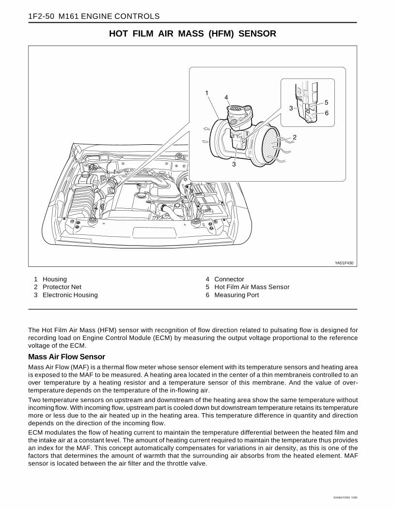
HOT FILM AIR MASS (HFM) SENSOR
YAD1F430
The Hot Film Air Mass (HFM) sensor with recognition of flow direction related to pulsating flow is designed forrecording load on Engine Control Module (ECM) by measuring the output voltage proportional to the referencevoltage of the ECM.
Mass Air Flow SensorMass Air Flow (MAF) is a thermal flow meter whose sensor element with its temperature sensors and heating areais exposed to the MAF to be measured. A heating area located in the center of a thin membraneis controlled to anover temperature by a heating resistor and a temperature sensor of this membrane. And the value of over-temperature depends on the temperature of the in-flowing air.
Two temperature sensors on upstream and downstream of the heating area show the same temperature withoutincoming flow. With incoming flow, upstream part is cooled down but downstream temperature retains its temperaturemore or less due to the air heated up in the heating area. This temperature difference in quantity and directiondepends on the direction of the incoming flow.
ECM modulates the flow of heating current to maintain the temperature differential between the heated film andthe intake air at a constant level. The amount of heating current required to maintain the temperature thus providesan index for the MAF. This concept automatically compensates for variations in air density, as this is one of thefactors that determines the amount of warmth that the surrounding air absorbs from the heated element. MAFsensor is located between the air filter and the throttle valve.
1 Housing2 Protector Net3 Electronic Housing
4 Connector5 Hot Film Air Mass Sensor6 Measuring Port
M161 ENGINE CONTROLS 1F2-51
SSANGYONG Y200
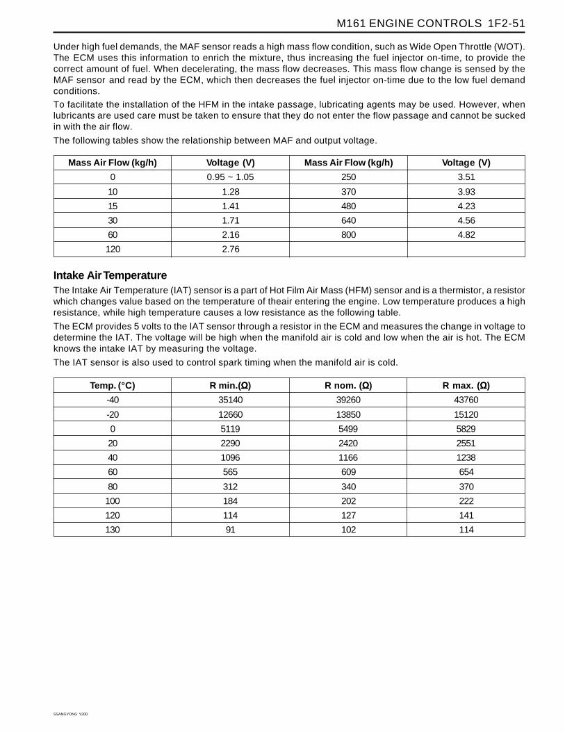
Intake Air TemperatureThe Intake Air Temperature (IAT) sensor is a part of Hot Film Air Mass (HFM) sensor and is a thermistor, a resistorwhich changes value based on the temperature of theair entering the engine. Low temperature produces a highresistance, while high temperature causes a low resistance as the following table.
The ECM provides 5 volts to the IAT sensor through a resistor in the ECM and measures the change in voltage todetermine the IAT. The voltage will be high when the manifold air is cold and low when the air is hot. The ECMknows the intake IAT by measuring the voltage.
The IAT sensor is also used to control spark timing when the manifold air is cold.
Under high fuel demands, the MAF sensor reads a high mass flow condition, such as Wide Open Throttle (WOT).The ECM uses this information to enrich the mixture, thus increasing the fuel injector on-time, to provide thecorrect amount of fuel. When decelerating, the mass flow decreases. This mass flow change is sensed by theMAF sensor and read by the ECM, which then decreases the fuel injector on-time due to the low fuel demandconditions.
To facilitate the installation of the HFM in the intake passage, lubricating agents may be used. However, whenlubricants are used care must be taken to ensure that they do not enter the flow passage and cannot be suckedin with the air flow.
The following tables show the relationship between MAF and output voltage.
Temp. (°C)
-40
-20
0
20
40
60
80
100
120
130
R min.(ΩΩΩΩΩ)
35140
12660
5119
2290
1096
565
312
184
114
91
R nom. (ΩΩΩΩΩ)
39260
13850
5499
2420
1166
609
340
202
127
102
R max. (ΩΩΩΩΩ)
43760
15120
5829
2551
1238
654
370
222
141
114
Mass Air Flow (kg/h)
0
10
15
30
60
120
Voltage (V)
0.95 ~ 1.05
1.28
1.41
1.71
2.16
2.76
Mass Air Flow (kg/h)
250
370
480
640
800
Voltage (V)
3.51
3.93
4.23
4.56
4.82
SSANGYONG Y200
1F2-52 M161 ENGINE CONTROLS
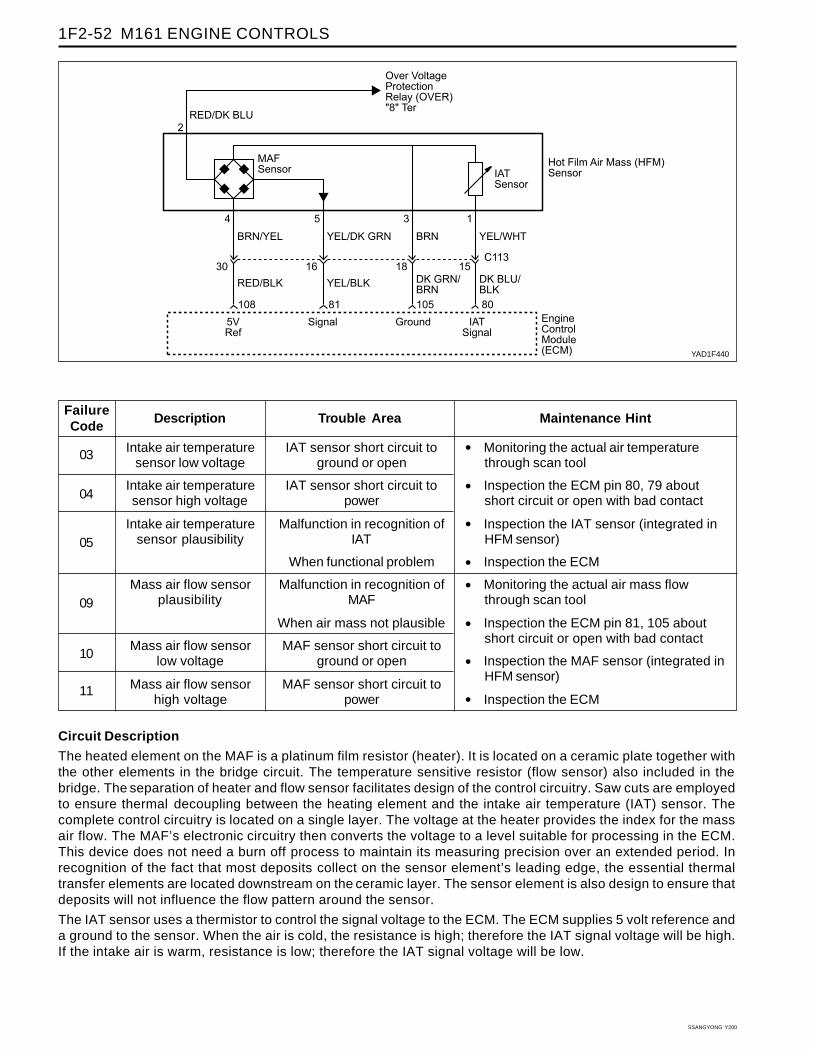
YAD1F440
Circuit Description
The heated element on the MAF is a platinum film resistor (heater). It is located on a ceramic plate together withthe other elements in the bridge circuit. The temperature sensitive resistor (flow sensor) also included in thebridge. The separation of heater and flow sensor facilitates design of the control circuitry. Saw cuts are employedto ensure thermal decoupling between the heating element and the intake air temperature (IAT) sensor. Thecomplete control circuitry is located on a single layer. The voltage at the heater provides the index for the massair flow. The MAF’s electronic circuitry then converts the voltage to a level suitable for processing in the ECM.This device does not need a burn off process to maintain its measuring precision over an extended period. Inrecognition of the fact that most deposits collect on the sensor element’s leading edge, the essential thermaltransfer elements are located downstream on the ceramic layer. The sensor element is also design to ensure thatdeposits will not influence the flow pattern around the sensor.
The IAT sensor uses a thermistor to control the signal voltage to the ECM. The ECM supplies 5 volt reference anda ground to the sensor. When the air is cold, the resistance is high; therefore the IAT signal voltage will be high.If the intake air is warm, resistance is low; therefore the IAT signal voltage will be low.
FailureCode
Description Trouble Area Maintenance Hint
Intake air temperaturesensor low voltage
Intake air temperaturesensor high voltage
Intake air temperaturesensor plausibility
Mass air flow sensorplausibility
Mass air flow sensorlow voltage
Mass air flow sensorhigh voltage
IAT sensor short circuit toground or open
IAT sensor short circuit topower
Malfunction in recognition ofIAT
When functional problem
Malfunction in recognition ofMAF
When air mass not plausible
MAF sensor short circuit toground or open
MAF sensor short circuit topower
• Monitoring the actual air temperaturethrough scan tool
• Inspection the ECM pin 80, 79 aboutshort circuit or open with bad contact
• Inspection the IAT sensor (integrated inHFM sensor)
• Inspection the ECM
• Monitoring the actual air mass flowthrough scan tool
• Inspection the ECM pin 81, 105 aboutshort circuit or open with bad contact
• Inspection the MAF sensor (integrated inHFM sensor)
• Inspection the ECM
03
04
05
09
10
11
M161 ENGINE CONTROLS 1F2-53
SSANGYONG Y200
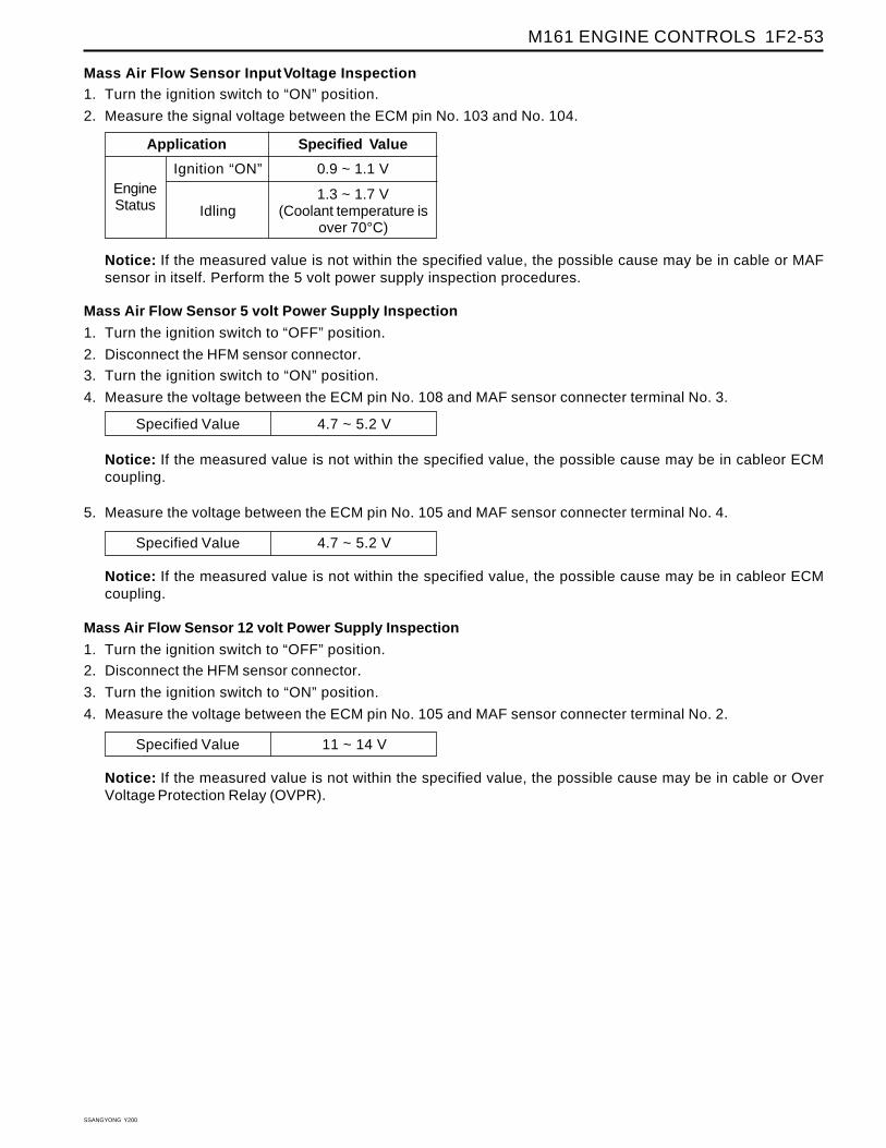
Mass Air Flow Sensor Input Voltage Inspection1. Turn the ignition switch to “ON” position.
2. Measure the signal voltage between the ECM pin No. 103 and No. 104.
Notice: If the measured value is not within the specified value, the possible cause may be in cableor ECMcoupling.
Specified Value 4.7 ~ 5.2 V
Notice: If the measured value is not within the specified value, the possible cause may be in cableor ECMcoupling.
Mass Air Flow Sensor 12 volt Power Supply Inspection
1. Turn the ignition switch to “OFF” position.
2. Disconnect the HFM sensor connector.
3. Turn the ignition switch to “ON” position.
4. Measure the voltage between the ECM pin No. 105 and MAF sensor connecter terminal No. 2.
Ignition “ON”
Idling
EngineStatus
Specified ValueApplication
0.9 ~ 1.1 V
1.3 ~ 1.7 V(Coolant temperature is
over 70°C)
Notice: If the measured value is not within the specified value, the possible cause may be in cable or MAFsensor in itself. Perform the 5 volt power supply inspection procedures.
Mass Air Flow Sensor 5 volt Power Supply Inspection
1. Turn the ignition switch to “OFF” position.
2. Disconnect the HFM sensor connector.
3. Turn the ignition switch to “ON” position.
4. Measure the voltage between the ECM pin No. 108 and MAF sensor connecter terminal No. 3.
Specified Value 4.7 ~ 5.2 V
5. Measure the voltage between the ECM pin No. 105 and MAF sensor connecter terminal No. 4.
Specified Value 11 ~ 14 V
Notice: If the measured value is not within the specified value, the possible cause may be in cable or OverVoltage Protection Relay (OVPR).