Embed Size (px)
Citation preview

Hot Food Deli Case MODELS WDC, TSW, TCW, SSW, CSW Service Manual Serial Numbers 122556 and Higher

Warranty Information LIMITED ONE YEAR WARRANTY BKI (The “Company”) warrants to the original purchaser/user, that at time of shipment from the Company factory, this equipment will be free from defect in materials and workmanship. Written notice of a claim under this Warranty must be given within ONE YEAR AND THREE MONTHS from date of shipment from the factory. Defective conditions caused by abnormal use or misuse, lack of maintenance, damage by third parties, alterations by unauthorized personnel, acts of God, failure to follow installation instructions or any other events beyond the control of the company will NOT be covered under Warranty. The obligation of the Company under this Warranty shall be limited to repairing or replacing (at the option of the company) any part which is defective in reasonable opinion of the Company. The user will have the responsibility and expense of removing and returning the defective part to the Company as well as the cost of reinstalling the replacement or repaired part. IN NO EVENT SHALL THE COMPANY BE LIABLE FOR LOSS OF USE, LOSS OF REVENUE OR LOSS OF PRODUCT OR PROFIT OR FOR INDIRECT OR CONSEQUENTIAL DAMAGES INCLUDING BUT NOT LIMITED TO, FOOD SPOILAGE OR PRODUCT LOSS. WARRANTY DOES NOT COVER GLASS BREAKAGE. THE ABOVE WARRANTY IS EXCLUSIVE AND ALL OTHER WARRANTIES, EXPRESS OR IMPLIED, ARE EXCLUDED INCLUDING THE IMPLIED WARRANTIES OF MERCHANTABILITY AND FITNESS FOR A PARTICULAR PURPOSE. THIS WARRANTY SHALL APPLY ONLY WITHIN THE CONTINENTAL UNITED STATES, ITS TERRITORIES, AND POSSESSIONS AND IN CANADA.
LIMITED NINETY DAY LABOR WARRANTY
All labor necessary to repair or replace factory defective parts will be performed, without charge, to the end user, by service personnel of a BKI Authorized Distributor during the first ninety days after the date of installation of the new equipment.
Replacement parts: Any appliance replacement part, except lamps and fuses, which proves to be defective in material or workmanship within 90 days from date of original installation will be repaired or replaced without charge F.O.B. Factory, Simpsonville, S.C. or F.O.B. authorized distributor.
Hot Food Deli Case Table of Contents
1
Table of Contents Table of Contents........................................................................................................................................1 Introduction .................................................................................................................................................2
Safety Precautions....................................................................................................................................2 Safety Signs and Messages.................................................................................................................2 Specific Precautions.............................................................................................................................3 Safe Work Practices.............................................................................................................................3
Installation ...................................................................................................................................................5 Unpacking and Handling...........................................................................................................................5 Floor Model ...............................................................................................................................................5
Leveling ................................................................................................................................................5 Kick Plate Mounting..............................................................................................................................6 End Panel Mounting .............................................................................................................................7
Pedestal Model .........................................................................................................................................8 Leveling ................................................................................................................................................8 Front and Rear Cover Attachment .......................................................................................................9 End Panel Mounting .............................................................................................................................9
Counter Model ........................................................................................................................................10 Wiring......................................................................................................................................................10 Joining WDCTY Cases ...........................................................................................................................11
Replacement Parts....................................................................................................................................12 Control Panel ..........................................................................................................................................12 Canopy & Lift Hardware..........................................................................................................................13 Heated Shelf ...........................................................................................................................................14
Wiring Diagrams........................................................................................................................................15

Hot Food Deli Case Introduction
2
Introduction Congratulations! You have chosen a Hot Food Deli Case that will give you many years of fine service from the original manufacturer, BKI. The BKI name and trademark on this unit assures you of the finest in design and engineering -- that it has been built with care and dedication -- using the best materials available. Attention to the operating instructions regarding proper installation, operation, and maintenance will result in long lasting dependability to insure the highest profitable return on your investment.
PLEASE READ THIS ENTIRE MANUAL BEFORE OPERATING THE UNIT. If you have any questions, please contact your BKI Distributor. If they are unable to answer your questions, contact the BKI Technical Service Department, toll free: 1-800-927-6887. Outside the U.S., call 1-864-963-3471.
This unit is to be sealed to the floor after installation to conform to NSF requirements. (Dow Corning RTV #732 Multi purpose Sealant.)
Safety Precautions Always follow recommended safety precautions listed in this manual. Below is the safety alert symbol. When you see this symbol on your equipment, be alert to the potential for personal injury or property damage.
Safety Signs and Messages The following Safety signs and messages are placed in this manual to provide instructions and identify specific areas where potential hazards exist and special precautions should be taken. Know and understand the meaning of these instructions, signs, and messages. Damage to the equipment, death or serious injury to you or other persons may result if these messages are not followed.
This message indicates an imminently hazardous situation which, if not avoided, will result in death or serious injury.
This message indicates a potentially hazardous situation, which, if not avoided, could result in death or serious injury.
This message indicates a potentially hazardous situation, which, if not avoided, may result in minor or moderate injury. It may also be used to alert against unsafe practices.
This message is used when special information, instructions or identification are required relating to procedures, equipment, tools, capacities and other special data.

Hot Food Deli Case Introduction
3
Specific Precautions
Equipotential Ground Plane When a high current flows through a conductor, differences in potential appear between the conductor and nearby metallic surfaces near the appliance. As a result, sparks may be produced between the appliance and surrounding metal surfaces. These sparks could cause serious injury, damage, or fire.
BKI provides an Equipotential ground terminal for the connection of a bonding conductor after the installation of the appliance per lEC60417-1. This terminal is located on the inside of the Power Entry Supply box near the Earth connection and is marked with this symbol.
Safe Work Practices
Beware of High Voltage This equipment uses high voltage. Serious injury can occur if you or any untrained or unauthorized person installs, services, or repairs this equipment. Always Use an Authorized Service agent to Service Your Equipment
Keep this manual with the Equipment This manual is an important part of your equipment. Always keep it near for easy access.
If you need to replace this manual, contact: BKI Technical Services Department P.O. Box 80400 Simpsonville, S.C. 29680-0400 Or call toll free: 1-800-927-6887 Outside the U.S., call 864-963-3471
Protect Children Keep children away from this equipment. Children may not understand that this equipment is dangerous for them and others. NEVER allow children to play near or operate your equipment.

Hot Food Deli Case Introduction
4
Keep Safety Labels Clean and in Good Condition Do not remove or cover any safety labels on your equipment. Keep all safety labels clean and in good condition. Replace any damaged or missing safety labels. If you need new safety labels, contact: BKI Technical Services Department P.O. Box 80400 Simpsonville, S.C. 29680-0400 Or call toll free: 1-800-927-6887 Outside the U.S., call 864-963-3471
911
Be Prepared for Emergencies Be prepared for fires, injuries, or other emergencies. Keep a first aid kit and a fire extinguisher near the equipment. You must use a 40-pound Type BC fire extinguisher and keep it within 25 feet of your equipment. Keep emergency numbers for doctors, ambulance services, hospitals, and the fire department near your telephone.
Know your responsibilities as an Employer • Make certain your employees know how to operate the equipment. • Make certain your employees are aware of the safety precautions
on the equipment and in this manual. • Make certain that you have thoroughly trained your employees
about operating the equipment safely. • Make certain the equipment is in proper working condition. If you
make unauthorized modifications to the equipment, you will reduce the function and safety of the equipment.

Hot Food Deli Case Installation
5
Installation
Unpacking and Handling YOU are responsible for filling all freight claims with the delivering truck line. Inspect all cartons and crates for damage as soon as they arrive. If damage to cartons or crates is found, or if a shortage is found, note this on the bill of lading (all copies) prior to signing. If damage is found when the equipment is opened, immediately call the delivering truck line and follow up the call with a written report indicating concealed damage to your shipment. Ask for an immediate inspection of your concealed damage item. Packaging material MUST be retained to show the inspector from the truck line.
Do not walk on top of deli cases or damage to the cases and serious personal injury could occur. The cases are not structurally designed to support excessive external loading such as the weight of a person. Do not place heavy objects on the deli cases.
Move the deli case as close as possible to its permanent location before moving the case off of the shipping pallet. Make certain there are no separately packed accessories before discarding packaging. During shipment, the lubricant in the gas springs may have settled. This can cause the glass not to remain open in the raised position. To avoid this, fully raise and lower the glass manually 4 or 5 times.
Floor Model
Leveling Deli cases must be installed level to insure proper operation and alignment to adjoining equipment. Use a carpenter’s level as shown in Figure 1. Begin lineup leveling from the highest point of the store floor.
BLACK KICK PLATES (FRONT & BACK)
LOWER
BLACK SHEET METAL SCREWS
LEG LEVELER
RAISE
LEVEL CASE
BOLT BASES OF ADJOININGCASES TOGETHER AT THESE (4) LOCATIONS
COUNTERTOP ENDFLANGE
Figure 1. Floor Model - Leveling & Kick Plate Mounting

Hot Food Deli Case Installation
6
1. Level the case using the leg levelers at the corners of the case (Figure 1). 8 ft. cases have an additional pair of leg levelers in the center – don’t forget to adjust these too.
2. Raise the low end of the case to level it, do not lower the high end.
3. Check for level side-to-side and front-to-back.
4. If you are installing adjoining cases, position the next case in line beside the level case and proceed to the next step.
5. Level this case in the same manner.
6. When level, bolt the two cases together at the locations shown in Figure 1. NOTE: None of the end components shown in Figure 2 should be attached to adjoining case ends If the cases have been properly leveled, the front panels and counter tops should align with a small, uniform gap between the front panels of the two cases.
7. Proceed in the same manner until all the cases in the line are level and bolted together.
8. Complete the line up by slipping the Counter Top Joint Cover over the end flanges of the adjoining counter tops.
Kick Plate Mounting A black vinyl-covered kick plate is provided for the front and back of each case.
1. Slide the front kick plate (the wider of the two) behind the lower finished front panel of the case (see Figure 1).
2. Make certain that the ends of the kick plate are flush with the ends of the lower finished front panel and that the kick plate is flush to the floor.
3. Drill 5/32” diameter holes in the case base to match the pre-drilled holes in the kick plate.
4. Attach the kick plate to the case base with the black sheet metal screws provided.
5. Mount the back kick plate to the case in the same manner.
6. Place the End Kick Plates in position (see Figure 2).
NOTE: There are left and right hand parts. The longer end flange faces toward the front of the case with the black side out. The End Kick Plates fit over the ends of the front and back kick plates and flush to the floor.

Hot Food Deli Case Installation
7
End Panel Mounting 1. Now, attach the End Trim Panels to the base ends. The studs on the Trim Panels pass through
the mounting holes in the base ends (see Figure 2). Both End Trim Panels are the same.
2. If the panel does not align properly turn it end for end. The panels are secured from inside with the #10 Palnuts provided.
3. Attach the End Panels to the ends of the case(s) as shown in Figure 2 using the shoulder screws provided. For Glass End Panels only, slide the plastic bushings provided over the shoulder screws before inserting the screw into the glass panel. Be careful that the screws do not bind in the holes in the glass panel. NOTE: If the ends are already attached to the case, the End Kick Plates can be lowered to the floor. To do this loosen the End Trim Panel nuts from inside the case then slide the Kick Plates flush with the floor and tighten the Trim Panel nuts.
4. These cases are to be sealed to the floor if required by local health codes. Seal the kick plates to the floor using a silicone-type sealant (Dow Corning RTV #732 or equivalent).
SHOULDER SCREWS ATTACH GLASS END PANEL TO THESE THREADED INSERTS
END PANEL
END KICK PLATE HELD CAPTIVE
BEHIND TRIM PANEL
END TRIM PANEL
END KICK PLATE
TRIM PANEL STUDS THRU THESE (4) HOLES – ATTACH FROM INSIDE BASE w/#10-24 PALNUT
Figure 2. Floor Model - End Kick Plate & End Panel Mounting

Hot Food Deli Case Installation
8
Pedestal Model Pedestal mounted cases are provided with a mounting frame that runs the full length of the case. This allows the pedestals to be located at any point along the length of the case. Each case should be supported by at least two pedestals. One pedestal can support the ends of two adjoining cases. If in doubt, consult the factory for assistance in determining the proper pedestal locations for your particular installation.
LEVEL CASE
RETAINING CLIP CLAMPS PEDESTAL FRAME TO BOTTOM FLANGE OF CASE FRAME
REAR COVER(PAINTED or STAINLESS)
INSTALL FIRST
MOUNTING RAILS ONCASE FIT INSIDE PEDESTAL ENDS
BOLT FRAMES OF AJOININGCASES TOGETHER AT THESE
(3) LOCATIONS
FRONT COVER (PAINTED or STAINLESS) FITS OVER REAR COVER
PEDESTALFRAMELEG
LEVELER
RAISELOWER
Figure 3. Pedestal Model - Leveling and Cover Attachment
Leveling Deli cases must be installed level to insure proper operation and alignment to adjoining equipment. Use a carpenter’s level as shown in Figure 3. Begin lineup leveling from the highest point of the store floor.
1. Level the case using the leg levelers at the corners of the pedestals (see Figure 3).
2. Raise the low end of the case to level it, do not lower the high end.
3. Check for level side-to-side and front-to-back.
4. If you are installing adjoining cases, position the next case in line beside the level case and proceed to the next step.
5. Level this case in the same manner.
6. When level, bolt the two cases together at the locations shown in Figure 3. If the cases have been properly leveled, the front panels and counter tops should align with a small, uniform gap between the front panels of the two cases.

Hot Food Deli Case Installation
9
7. Proceed in the same manner until all the cases in the line are level and bolted together.
8. Complete the line up by slipping the Counter Top Joint Cover over the ends flanges of the adjoining counter tops.
Front and Rear Cover Attachment 1. Slide the Rear Cover over the Pedestal Frame first (see Figure 3). Then slide the Front Cover
over the Frame with the sides of the Front Cover lapping over the side of the Rear Cover. The Front Cover will extend approximately 4-1/2” from the front of the frame.
2. Drill two 5/32” diameter holes in each side of the Pedestal Frame to match the predrilled holes in the covers.
3. Secure the covers to the frame using the #8 sheet metal screws provided.
4. These cases are to be sealed to the floor if required by local health codes. Seal the pedestal covers to the floor using a silicone-type sealant (Dow Corning RTV #732 or equivalent).
End Panel Mounting
END PANEL
¼” –20 NUTS ATTACHLOWER SHOULDER BOLTS FROM BACKSIDEOF END PANEL
Figure 4. Pedestal Model - End Panel Mounting
1. Attach the End Panels to the ends of the case(s) as shown in Figure 4 using the shoulder screws
provided.
2. Attach the (2) lower shoulder screws to the End Panel with the ¼”-20 nuts provided. For Glass End Panels only, slide the plastic bushings provided over the shoulder screws before inserting the screw into the glass panel. Be careful that the screws do not bind in the holes in the glass panel.

Hot Food Deli Case Installation
10
Counter Model Counter Mounted cases must be mounted on a level surface that can support the weight of the case and it contents. Use a carpenter’s level as shown in Figure 3 to level the case. These cases are to be sealed to the counter if required by local health codes. Seal the perimeter of the case to the counter using a silicone-type sealant (Dow Corning RTV #732 or equivalent). Attach the End Panels to the ends of the case as shown in Figure 4 using the shoulder screws provided. The (2) lower shoulder screws shown in Figure 4 are not required on counter mounted cases. For Glass End Panels only, slide the plastic bushings provided over the shoulder screws before inserting the screw into the glass panel. Be careful that the screws do not bind in the holes in the glass panel.
Wiring A wiring diagram for the specific model is shipped with the deli case. The wiring diagram provides electrical specifications, an electrical schematic and a parts list. Refer to this wiring diagram and the deli case serial number plate for electrical information. Field wiring must be sized for the components amperes printed on the serial number plate. Actual ampere draw may be less than specified. All electrical connections should be in compliance with the NEC and all applicable local codes by a licensed electrician. Refer to the wiring diagram furnished with your case for the electrical specifications. The power supply connection is located on the bottom of the well compartment of the case (see Figure 5). Two ¾ x 1 knockouts are provided for the required conduit connection. A second power supply connection for the oven is provided on oven combo cases. A wiring cutout is provided in the base bottom pan on floor model cases (see Figure 5). Refer to the case specification sheet for the location of this cutout. Remove the cover over the wiring cutout and route the wiring through the cutout. Cut a hole of the proper size and location in the cover for the conduit to pass through and reinstall the cover.
TERMINALACCESS COVER
(2) ¾” X 1”KNOCKOUTS
WIRING CUTOUTIN FLOOR MODEL BASE
Figure 5. Wiring Access

Hot Food Deli Case Installation
11
Joining WDCTY Cases 1. After leveling the cases and bolting the bases together, bolt the canopies together.
2. Remove the screws from the back of the top inner covers (with lights) on each case and allow
them to swing forward.
3. Connect the canopies using the ¼”-20 X 3” bolt and nut provided (see Figure 6, View A-A). Replace the top inside covers.
4. Mount the Platform, Counter Trim and Base Front Joint Covers by holding them in place and marking the hole locations on the case.
5. Make certain the joint covers are centered on the joint and that they align vertically with each other.
6. Drill the case holes 5/32” and attach joint covers with screws provided. Black screws are to be used on the Platform Cover and the Base Front Cover if painted black.
Figure 6. Joining WDCTY Cases

Hot Food Deli Case Replacement Parts
12
Replacement Parts Use the information in this section to identify replacement parts. To order replacement parts, call your local BKI sales and service representative. Before calling, please note the serial number on the rating tag affixed to the unit.
Control Panel
ITEM # PART # DESCRIPTION 1 C0285 CALROD, 208V 1000W C0286 CALROD, 240V 1000W C0296 CALROD, 208V 1112W C0298 CALROD, 240V 1112W 2 T0095 THERMOSTAT, 250V 450 DEG 3 K0049 KNOB, 6MM D SHAFT W/INDICATOR 4 S0141* SWITCH, INFINITE 240V-1245W 5 K0040 KNOB, S/S STRAT T0075 6 TB0064 TERM BLOCK 4 CONDUCTOR CTR TB0065 TERM BLOCK 4 CONDUCTOR W/MTG FOOT TB0066 TERM BLOCK 2 CONDUCTOR CTR TB0067 TERM BLOCK 2 CONDUCTOR TB0068 TERM BLOCK END PLATE TB0069 TERM BLOCK JUMPER BAR 7 B0084 BALLAST, 3XF32T8 OR 2XF40T8 8 S0341 SWITCH, DISCONNECT 4P 50A 9 CB0065 BREAKER, CIRCUIT 2.5A 250V 2P 10 PL0004 PILOT LIGHT, ROUND 250V
* - Replace S0141 with assembly AN6778710S containing the S0141switch, B0058 bracket and NUT282
nut.

Hot Food Deli Case Replacement Parts
13
Canopy & Lift Hardware
ITEM # PART # DESCRIPTION 1 FL0041* LAMP, FLUORESCENT GS U83001F25/T8 830 FL0042* LAMP, FLUORESCENT GS U83321F32/T8 830 FL0043* LAMP, FLUORESCENT GS U84001F40/T8 830 2 HI0014 LAMPHOLDER SHROUD, HI TEMP 3 HI0013 HARNESS, 8FT LIGHT CHANNEL 4 C0057 CERAMIC HEATER 400W FULL SIZE 220/240V 5 I0029 FIBERGLASS SLEEVING SIZE 2 3.5" 6 HI0105** GAS RAM 400N HUSSMANN IMPACT HI0108** GAS RAM 100N HUSSMANN IMPACT VH0432** GAS RAM 200 RADIAL HDWE VH0433** GAS RAM 300N RADIAL HDWE
* - To maintain NSF compliance, replace with BKI lamps only ** - Requires HI0110 Installation Tool

Hot Food Deli Case Replacement Parts
14
Heated Shelf
ITEM # PART # DESCRIPTION 1 FL0041* LAMP, FLUORESCENT GS U83001F25/T8 830 FL0042* LAMP, FLUORESCENT GS U83321F32/T8 830 FL0043* LAMP, FLUORESCENT GS U84001F40/T8 830 2 HI0014 LAMPHOLDER SHROUD, HI TEMP 3 HI0013 HARNESS, 8FT LIGHT CHANNEL 4 C0081 CALROD, 208V 1000W TSW4/8 SHELF C0082 CALROD, 208V 1500W TSW6 SHELF C0085 CALROD, 240V 1000W TSW4/8 SHELF C0086 CALROD, 240V 1500W TSW6 SHELF 5 T0006 THERMOSTAT, 110/208 300 DEG 6 G0108 GUARD, FRONT SHELF TSW 48" G0110 GUARD, FRONT SHELF TSW 72" CASE G0112 GUARD, FRONT SHELF DRTSW 48" G0113 GUARD, FRONT SHELF DRTSW 72" 7 G0109 GUARD, REAR SHELF TSW4-8 G0111 GUARD, REAR SHELF TSW6 8 K0050 KNOB, CLAMP W/1/4-20 X 1" STUD
* - To maintain NSF compliance, replace with BKI lamps only.

Hot Food Deli Case Wiring Diagrams
15
Wiring Diagrams Refer to the table below to find the wiring diagram associated with your unit. WIRING DIAGRAM DRAWING # FIGURE # PAGE # Model SSW-4/CSW-4 SB67893500
SB67894200 Figure 7 16
Model SSW-6/CSW-6 SB67893600 SB67894300
Figure 8 17
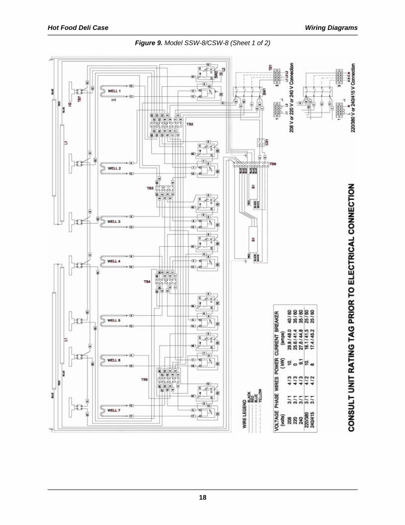
Model SSW-8/CSW-8 (Sheet 1 of 2) SB67893700 SB67894400
Figure 9 18
Model TSW-4/TCW-4 SB68492000 SB68492500
Figure 10 20
Model TSW-6/TCW-6 SB68492100 SB68492600
Figure 11 21
Model TSW-8/TCW-8 (Sheet 1 of 2) SB68492200 SB68492700
Figure 12 22
Model WDC-3 SB67695600 SB67696200
Figure 13 24
Model WDC-4/2L SB67792800 SB67793800
Figure 14 25
Model WDC-4/2R SB67792900 SB67793900
Figure 15 26
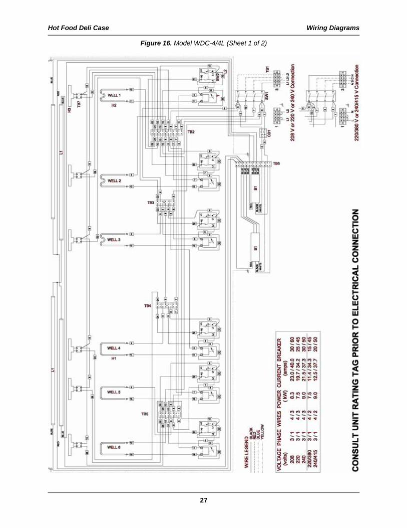
Model WDC-4/4L (Sheet 1 of 2) SB67793000 SB67794000
Figure 16 27
Model WDC-4/4R (Sheet 1 of 2) SB67793100 SB67794100
Figure 17 29
Model WDC-5 SB67695800 SB67696400
Figure 18 31
Model WDC-6/2L (Sheet 1 of 2) SB67793300 SB67794200
Figure 19 32
Model WDC-6/2R (Sheet 1 of 2) SB67793700 SB67794300
Figure 20 34
Model WDC-7 (Sheet 1 of 2) SB67695900 SB67696500
Figure 21 36

Hot Food Deli Case Wiring Diagrams
16
Figure 7. Model SSW-4/CSW-4

Hot Food Deli Case Wiring Diagrams
17
Figure 8. Model SSW-6/CSW-6
Hot Food Deli Case Wiring Diagrams
18
Figure 9. Model SSW-8/CSW-8 (Sheet 1 of 2)

Hot Food Deli Case Wiring Diagrams
19
Figure 9. Model SSW-8/CSW-8 (Sheet 2 of 2)

Hot Food Deli Case Wiring Diagrams
20
Figure 10. Model TSW-4/TCW-4

Hot Food Deli Case Wiring Diagrams
21
Figure 11. Model TSW-6/TCW-6

Hot Food Deli Case Wiring Diagrams
22
Figure 12. Model TSW-8/TCW-8 (Sheet 1 of 2)

Hot Food Deli Case Wiring Diagrams
23
Figure 12. Model TSW-8/TCW-8 (Sheet 2 of 2)

Hot Food Deli Case Wiring Diagrams
24
Figure 13. Model WDC-3

Hot Food Deli Case Wiring Diagrams
25
Figure 14. Model WDC-4/2L

Hot Food Deli Case Wiring Diagrams
26
Figure 15. Model WDC-4/2R
Hot Food Deli Case Wiring Diagrams
27
Figure 16. Model WDC-4/4L (Sheet 1 of 2)

Hot Food Deli Case Wiring Diagrams
28
Figure 16. Model WDC-4/4L (Sheet 2 of 2)

Hot Food Deli Case Wiring Diagrams
29
Figure 17. Model WDC-4/4R (Sheet 1 of 2)

Hot Food Deli Case Wiring Diagrams
30
Figure 17. Model WDC-4/4R (Sheet 2 of 2)

Hot Food Deli Case Wiring Diagrams
31
Figure 18. Model WDC-5

Hot Food Deli Case Wiring Diagrams
32
Figure 19. Model WDC-6/2L (Sheet 1 of 2)

Hot Food Deli Case Wiring Diagrams
33
Figure 19. Model WDC-6/2L (Sheet 2 of 2)

Hot Food Deli Case Wiring Diagrams
34
Figure 20. Model WDC-6/2R (Sheet 1 of 2)

Hot Food Deli Case Wiring Diagrams
35
Figure 20. Model WDC-6/2R (Sheet 2 of 2)

Hot Food Deli Case Wiring Diagrams
36
Figure 21. Model WDC-7 (Sheet 1 of 2)

Hot Food Deli Case Wiring Diagrams
37
Figure 21. Model WDC-7 (Sheet 2 of 2)

P.O. Box 80400, Simpsonville, S.C. 29680-0400, USA http://www.bkideas.com Made and printed in the U.S.A LI0193/0804