Embed Size (px)
Citation preview


Hot stamping of ultra high strength steel:
A key technology for lightweight automotive design
Asst. Prof. Vitoon Uthaisangsuk, Dr.-Ing.
Department of Mechanical Engineering, Faculty of Engineering
King Mongkut's University of Technology Thonburi

Overview • Introduction
• Material and coating
• Heating
• Forming and quenching
• Thermo-mechanical behavior
• Subsequent processing
• Hot stamped parts with tailored properties

Overview • Introduction • Material and coating
• Heating
• Forming and quenching
• Thermo-mechanical behavior
• Subsequent processing
• Hot stamped parts with tailored properties

Why Hot-stamping ?
Standard Requirements Customers expectations
CO2 emission
Corrosion protection
Security
Weight reduction
Security
Durability
Ultra High Strength Steels (UHSS)
Pre-coated steels
Source: ArcelorMittal, Hot Stamping with USIBOR1500P® 2010

Source: ArcelorMittal, Hot Stamping with USIBOR1500P® 2010
Main properties after hot stamping

Source: http://mercedes-benz-blog.blogspot.com/2010/03/new-mercedes-benz-e-class-cabriolet_2785.html
Steel sheet concept for automotive parts
2010 The new Mercedes-Benz E-Class

Source: http://boronextrication.com/tag/list-of-vehicles-with-boron-and-uhss
Steel sheet concept for automotive parts
2011 Volvo V70 Body Structure

Source: http://carskeleton.blogspot.com/2012_04_01_archive.html
Steel sheet concept for automotive parts
2012 Audi A3 body Structure

Steel sheet concept for automotive parts
Source: ArcelorMittal, Hot Stamping with USIBOR1500P® 2010

Hot Stamping Demand
Source: Neugebauer et al. 2012

Variants of hot stamping process
Blank
Blank
Cold pre-forming Austenitization
Austenitization
Transfer
Transfer Forming and quenching
Calibration and quenching
Part
Part
Direct hot stamping
Indirect hot stamping
Source: Karbasian and Tekkaya 2010
min. 5 min
5 – 10 s

Blank Austenitization Transfer Forming and quenching Part
Direct hot stamping
Advantages: • Saving cost of pre-forming
• Accelerating production rate
• Blank is flat which not only saves heating area and energy,
but also can be heated by a variety of heating methods.
Disadvantages: • It cannot be used for forming automobile parts
with complex shapes.
• Laser cutting facilities are needed.
• Design of cooling system for stamping dies is more complex.
Source: P. Hu, N. Ma, L.Z. Liu and Y.G. Zhu 2013

Blank Cold pre-forming Austenitization Transfer Calibration and quenching
Part
Indirect hot stamping
Advantages: • Producing parts with complex shape is possible.
• Ensuring the martensitic microstructure of the blank followed by
complete quenching.
• Blank can be previously processed by trimming, flanging,
punching and other processing after being pre-formed so that it will be easier for processing after it is quenched.
Source: P. Hu, N. Ma, L.Z. Liu and Y.G. Zhu 2013
Overview • Introduction
• Material and coating • Heating
• Forming and quenching
• Thermo-mechanical behavior
• Subsequent processing
• Hot stamped parts with tailored properties

22MnB5
Source: Salzgitter Flachstahl 22MnB5 Edition: 07/07
After hot stamping: YS – 1000 MPa
TS – 1500 MPa
Elongation – < 6%
Microstructure – Martensite

Ultra High Strength Steels (UHSS)
Source: Karbasian and Tekkaya 2010 and Geiger 2008

Ultra High Strength Steels (UHSS)
Source: Karbasian and Tekkaya 2010

Uncoated 22MnB5 sheet
First applied for automotive parts by company HARDTECH
(today GESTAMP-HARDTECH) in Sweden
Source: ArcelorMittal: Hot Stamping with USIBOR1500P® 2010 Scale formation on uncoated material

Al-Si coating
- No cold forming
- No scale formation
- No sandblasting
- Excellent geometrical accuracy
- Very good corrosion protection
Pre-coated USIBOR1500P is used for direct hot stamping. It is metallic coating, that first realized by
TKS-SOFEDIT and developed for the first serial hot stamping by ARCELOR MITTAL. The coating is generated in a continuous hot-dip galvanizing process and consists of 10% Si, 3% Fe and 87% Al.
Source: ArcelorMittal: Hot Stamping with USIBOR1500P® 2010

Process parameters recommended by AM for USIBOR1500P
Heat treatment Austenitization and coating alloying: 880 – 930°C, 4 –10 min
Heating rate: < 12°C/s
Atmosphere in the furnace: air, no combustion gas
Transfer time furnace - press About 7 seconds
Quenching
Quenching speed in the dies (average): >50°C/s
Water quenching: post-tempering may be necessary
Final temperature of the part: < 200°C after die-quenching.
Trimming
Laser trimming or die trimming
Source: ArcelorMittal: Hot Stamping with USIBOR1500P® 2010

Effect of heat treatment
Source: ArcelorMittal, Hot Stamping with USIBOR1500P® 2010
As delivered After hot stamping
Austenitization + Stamping + Quenching leads to a martensitic structure and significant increase of tensile properties and hardness.

CTT diagram with and without deformation
Source: ArcelorMittal: Hot Stamping with USIBOR1500P® 2010

Diffusion process in Al-Si coating layer
During heat treatment, Fe diffuses
in the Al-Si layer. Complex Al-Si-
Fe intermetallic layers & growth is
formed in coating thickness. This
layer has higher melting point and
prevents the formation of scales.
Source: ArcelorMittal: Hot Stamping with USIBOR1500P® 2010
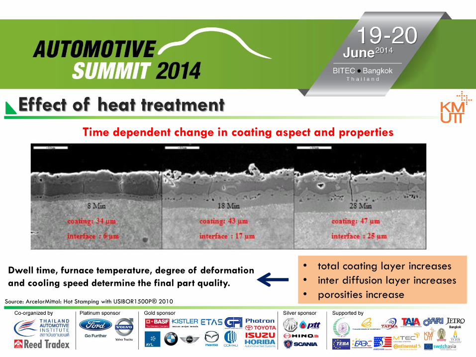
Effect of heat treatment
Source: ArcelorMittal: Hot Stamping with USIBOR1500P® 2010
• total coating layer increases
• inter diffusion layer increases
• porosities increase
Time dependent change in coating aspect and properties
Dwell time, furnace temperature, degree of deformation
and cooling speed determine the final part quality.

Effect of heat treatment
- Porosity
- Oxides at the surface
→ inhomogeneous current flow - poor
mechanical stability of coating (collapse)
→ Unstable welding parameters
- Less porosity
- Less oxides
→ homogenous current flow - good
mechanical stability of coating
→ stable welding parameters
Source: ArcelorMittal: Hot Stamping with USIBOR1500P® 2010
28 Min
Overheated
8 Min
Recommended

Drawbacks of Al-Si coating
This Al-Si coating provides enhanced anticorrosion properties. On the other hand, it has the
following drawbacks:
• High raw material cost
• A process window of 5 – 7 minutes is required in the heat treatment to allow the Al-Si material
to diffuse into the steel matrix and thereby to achieve its anticorrosion effect.
• During the heat treatment of Al-Si-coated sheet metal, a fusion phase occurs, which results in
intense thermochemical attack on the ceramic conveying rollers of the roller hearth furnace.
• Al-Si-coated blanks cannot be processed by the indirect method, since the coating with lower
forming limits would get damaged in the pre-forming step.
Source: Practical Handbook of Thermo-processing Technology VW-Kassel 2011
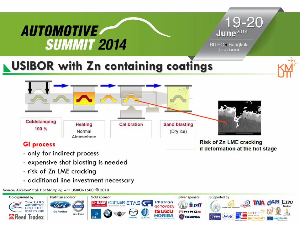
USIBOR with Zn containing coatings
Source: ArcelorMittal: Hot Stamping with USIBOR1500P® 2010
GI process
- only for indirect process
- expensive shot blasting is needed
- risk of Zn LME cracking
- additional line investment necessary

Hot stamping process with GA coating
- direct and indirect process possible
- compatible with existing hot
stamping lines
- No sand blasting necessary
- Sacrificial corrosion protection
Development of USIBOR1500P GA
(Zinc/ Iron or “galvannealed” coating)
Source: ArcelorMittal, Hot Stamping with USIBOR1500P® 2010

Comparison between coated and uncoated part (tunnel) after hot stamping
Coated tunnel
after hot forming
Uncoated tunnel
after hot forming
Source: Practical Handbook of Thermo-processing Technology VW-Kassel 2011

Overview • Introduction
• Material and coating
• Heating • Forming and quenching
• Thermo-mechanical behavior
• Subsequent processing
• Hot stamped parts with tailored properties

Influence of austenitization temperature and time
Source: Karbasian and Tekkaya 2010

Heating system
Source: DieDe 2009, Veit 2010, Karbasian 2010, Bader 2011, Billur and Altan 2012

Roller hearth furnace Direct process Over 80% of all heating systems in hot stamping applications are roller-hearth furnaces. Furnaces of this
type can be run with or without protective gas.
Source: Practical Handbook of Thermo-processing Technology Schwartz 2011
30 – 40 m

Roller hearth furnace Direct process
Source: Practical Handbook of Thermo-processing Technology Schwartz 2011
Note: Furnace length is essential due to two factors:
1. For AlSi-coated sheet metal, a process window of at least 300
seconds is specified for allowing the coating to diffuse far enough
into the steel matrix so that it can deliver its subsequent corrosion
protection properties plus good weldability. (Equipment used only
for uncoated blanks can be built up to 30% shorter than roller-
hearth furnaces used also for AlSi-coated blanks.)
2. Cold-rolling creates residual stresses in the sheet metal. These
may cause the blank to become distorted when heated rapidly.
Accordingly, the temperatures in the front zones of the roller-hearth furnaces must not be set too high.
- No need of product trays
- Sheet metal is placed directly on the conveying
rollers and passes through the furnace in this manner.

Roller hearth furnace Direct process It was found that a very strong thermochemical reaction occurs when the AlSi-coated sheet metal
comes into direct contact with the ceramic conveying rollers during the heat treatment. This effect calls for relatively frequent roller replacements which may impact plant availability.
Thermochemical attack on a conveying roller
Source: Practical Handbook of Thermo-processing Technology Schwartz 2011

Roller hearth furnace Direct process
Area of transition between coated and uncoated rollers after
heat-treatment of approx. 40,000 AlSi-coated blank. Coated rollers were made from a non-oxidic, aluphobic ceramic material.
Source: Practical Handbook of Thermo-processing Technology Schwartz 2011
Relying on the sol-gel process, a suspension was developed for
application to the conveying rollers by spray-coating. (0-sample = uncoated roller sample)

Roller hearth furnace Indirect process
Source: Practical Handbook of Thermo-processing Technology Schwartz 2011

Roller hearth furnace Indirect process
Source: Practical Handbook of Thermo-processing Technology Schwartz 2011
- In indirect process, pre-formed parts must pass
through the furnace on product support trays to
accommodate their complex shape.
- Since the parts are heat-treated in their uncoated
state, a furnace of this type needs to run with a
controlled atmosphere (i.e., protective gas) in order
to prevent oxidation of the part surface (scale
formation
- A return conveyor for the product trays in a closed loop is required.
Roller hearth furnace Indirect process
Source: Practical Handbook of Thermo-processing Technology Schwartz 2011
Disadvantages:
- Up to 50% more heating power (trays must be heated and cooled down during each press cycle)
- The trays are high-wear components. (a fairly short service life due to the cyclic thermal loads
Advantages:
- Trays may be used for AlSi-coated blanks so that thermochemical attack on the ceramic rollers is avoided.
- Highly complex geometry can be subjected to a heat treatment process prior to hot stamping. However,
this geometry is limited by the tray dimensions.

Conductive heating In this process, the decrease in temperature of the blank before forming is prevented by direct heating the sheet into die sets by means of the electrical resistance.
Source: Mori et al. 2009
- Inhomogeneous temperature along the length of component.
- By industrial application, this heating method is difficult for blanks with complex geometries.

Overview • Introduction
• Material and coating
• Heating
• Forming and quenching • Thermo-mechanical behavior
• Subsequent processing
• Hot stamped parts with tailored properties

Forming
tool steel
die design and construction
die coating
process parameters
die maintenance
Tool design for the hot stamping process Source: Karbasian and Tekkaya 2010

Heat transfer from the drawn part to the tool
- depends on surface scaling effects and gap between part and tool surface
Heat conductivity of the tool material
- depends on choice of tool material
Design of the cooling ducts
- defined by size location and distribution of the cooling ducts
Temperature and type of coolant
- Temperature difference between coolant and tool affects the heat transfer
Optimization of locations of cooling channels in hot stamping dies
Die design
Source: Naganathan and Altan 2010

Heat transfer from drawn part to tools
Heat transfer coefficient - depends on surface scaling effects and gap between part
and tool surface
Source: Geiger et al. 2008, Lechler 2009
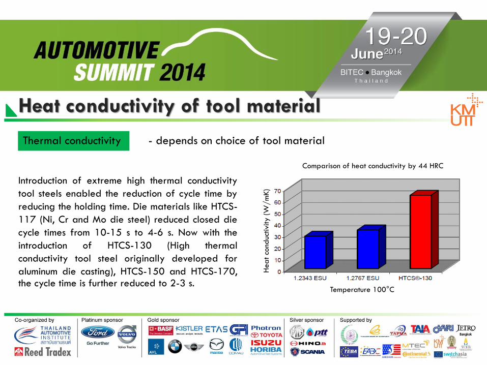
Heat conductivity of tool material
Thermal conductivity
Introduction of extreme high thermal conductivity
tool steels enabled the reduction of cycle time by
reducing the holding time. Die materials like HTCS-
117 (Ni, Cr and Mo die steel) reduced closed die
cycle times from 10-15 s to 4-6 s. Now with the
introduction of HTCS-130 (High thermal
conductivity tool steel originally developed for
aluminum die casting), HTCS-150 and HTCS-170, the cycle time is further reduced to 2-3 s.
- depends on choice of tool material
Temperature 100°C
Heat co
nduc
tivi
ty (W
/m
K)
Comparison of heat conductivity by 44 HRC

Design of cooling ducts
Convection coefficient - defined by size location and distribution of the cooling ducts
Source: Hoffmann et al. 2007, Shapiro 2009

Design of cooling ducts
Source: Kolleck et al. 2010
Current Practice: Cast-in or drilled cooling channels Proposed: near-surface cooling channels
- Cooling holes can be drilled. (Machining restriction must be
considered in the design of hole position.)
- Providing cooling holes as pipes in the casting mold.
- Using lasered blank segments that are screwed and form the tool surface with integrated cooling holes.

Die design The heat transfer between component and dies plays an important role.
The heat conductivity within
the tool can be considerably
influenced by the choice of
the tool material.
Another important factor with respect to heat drain is the design of the cooling ducts, which is defined by the size,
location, and distribution of the cooling ducts. The heat drain can be accelerated by using a coolant with a low
temperature, in order to increase the temperature difference between the coolant and the tool and therefore the resulting heat flux.
Source: Steinbeiss 2007

Overview • Introduction
• Material and coating
• Heating
• Forming and quenching
• Thermo-mechanical behavior • Subsequent processing
• Hot stamped parts with tailored properties

Thermal characteristics
Source: Karbasian and Tekkaya 2010

Phase transformation behavior
Source: Karbasian and Tekkaya 2010
- The transformation
from austenite (FCC)
into martensite (BCT)
causes an increase in
volume, which
influences the stress
distribution during
quenching.
- Volume fraction of
different phases,
residual stresses and
distortion of the work piece after cooling

Flow behavior
Source: Merklein and Lechler 2006

Forming limit curve
Source: Karbasian and Tekkaya 2010

Friction coefficient
Source: Karbasian and Tekkaya 2010

Microstructure evolution
Source: Karbasian and Tekkaya 2010 and ArcelorMittal 2012

FE simulation performance
Source: ArcelorMittal: Hot Stamping with USIBOR1500P® 2010
Overview • Introduction
• Material and coating
• Heating
• Forming and quenching
• Thermo-mechanical behavior
• Subsequent processing • Hot stamped parts with tailored properties

Laser cutting - Due to the contactless trimming laser, cutting does
not cause any tool wear or any failure on the cutting
edge in contrast to other cutting methods.
- There are nearly no limits with regard to the shape
of the parts to be trimmed.
- The achievable tolerances are influenced by the
stiffness of the laser machine and the holding fixture
of the part.
- The laser cutting time depends on the part geometry
and the movement of the laser machine.
Source: Karbasian and Tekkaya 2010, Albrecht 2011, Banik 2011, Weigert 2011, Osburg 2012

Hard cutting - So et al. (2009) showed that in the blanking process, the quality
of the sheared surface and dimension precision are influenced by
certain process parameters, such as punch speeds, blanking
angles, punch-die clearances, tool cutting edge geometries, and
mechanical properties of the material. No influence of the punch
speed on the sheared geometries and the blanking forces are
observed.
- Picas et al. (2008) showed that the high hardness of the punch
induces low wear of the cutting edge, but it becomes strongly
sensitive to high loads during its application, since considerable
micro-fractures occur along the cutting edge. An optimal
toughness-hardness compromise must be found to improve the
mechanical behavior of tools.
Source: Karbasian and Tekkaya 2010, Albrecht 2011, Banik 2011, Weigert 2011, Osburg 2012

Warm cutting - Cutting parts during quenching at elevated
temperatures
- A reduced cutting force and an optimized
cutting edge through a short process chain
- Selective heat treatment of the parts during
quenching for avoiding martensite structure.
Locally differentiated heat treatments can
be performed by employing tool materials
with different thermal conductivities designed
for improvement of posterior cutting.
Source: Karbasian and Tekkaya 2010, Albrecht 2011, Banik 2011, Weigert 2011, Osburg 2012

Developed Blanks
- The most cost-effective cutting method is pre-
developed blanking.
- This method requires a certain blank design
to achieve the desired part outline after
forming.
- The tolerances that can be achieved are
smaller than with cutting after hot forming.
Source: Karbasian and Tekkaya 2010, Hund 2011, Baniket et al 2011

Combining techniques
Source: Karbasian and Tekkaya 2010, Josefsson 2010

Zn-Fe coating
- The best resistance spot welding results are produced with
the double-pulse technology in combination with a DC source.
x-tec®
- The test of second and third generation x-tec® anti scaling
coatings by the integration of magnesium particles has shown the
suitability of the coatings for resistance spot welding.
- Applied atmosphere inside the furnace while heating the blanks
has a great influence on the spot-weldability. Heating in air (with
O2 content) causes the formation of oxide layers so that spot
welding cannot be applied.
Joining
Source: Karbasian and Tekkaya 2010, World auto steel 2014

Joining
Laser and gas metal arc welding
- For laser and gas metal arc welding, the cross-sections of the joints of the tested combinations show that the x-tec ® coating had no influence on the welding behavior.
No pores or other defects were detected inside the joints.
- This coating will flexibly work also with different substrates, e.g. H430LA for
manufacturing tailor welded blanks.
The coating layer and its chemical composition can cause failures during welding.
Source: Karbasian and Tekkaya 2010, Braun and Fritzsche 2009

Overview • Introduction
• Material and coating
• Heating
• Forming and quenching
• Thermo-mechanical behavior
• Subsequent processing
• Hot stamped parts with tailored properties

Tailored properties Fully martensitic transformation during hot stamping leads to a part with tensile strength of up to 1500 MPa and low
elongation of about 5%. But an improved crash performance of a vehicle structural component, such as B-pillar can be achieved by introducing regions which have an increased elongation for improved energy absorption.
Source: ThyssenKrupp 2012, Eller et al. 2010

Tool tempering
Source: Maikranz-Valentin 2007, Karbasian and Tekkaya 2010

Blank tempering
Source: Maikranz-Valentin 2007, Karbasian and Tekkaya 2010

Tailor rolled blanks
Source: mubea.com, Hover 2011

Tailored welded blanks
Source: ThyssenKrupp and ArcelorMittal

Hot stamped part with tailored properties
Source: Benteler Automotive 2010

Applications
Source: Karbasian and Tekkaya 2010

Crash test
VW Passat incorporating hot-
forming hardened steel parts.
After the crash test at 75 km/h,
the doors could be opened without problems.
Source: Practical Handbook of Thermo-processing Technology VW-Kassel 2011

Key Points
Source: World auto steel 2014
The goal of hot-forming is to heat a steel to temperatures high enough to
• increase forming parameters to allow successful forming of difficult stampings
• quench stamped part to form very high strength martensite
• avoid springback problems associated with higher strength steels.
Steel usually utilized is a 22MnB5 grade with yield strength of 340 MPa, tensile strength of 480 MPa and 20-30% total
elongation.
Heating above 850°C reduces the tensile strength to 100 MPa and increases the total elongation to 50-60%. The steel is
formed in dies under this condition.
The forming die is chilled to provide a quenching action while the stamping is still held in the die. The quenching action:
• transforms the steel microstructure to martensite
• The stamping shape is retained with almost zero springback.
Press speed is approximately two strokes per minute to allow sufficient quenching.
The reduced forming strength may allow for multiple stampings in one die without over loading press capacity.
The very high final strength of the stamped part severely limits post forming operations. No additional forming should be
attempted. Trimming, cutting, and piercing equipment must be built to overcome the strength of the final stamping. Laser
welding is often used.