Embed Size (px)
Citation preview
J. Cent. South Univ. (2016) 23: 2595−2603 DOI: 10.1007/s11771-016-3321-8
Hover performance estimation and validation of battery powered vertical takeoff and landing aircraft
WANG Bo(王波)1, 2, HOU Zhong-xi(侯中喜)1, LU Ya-fei(鲁亚飞)1, ZHU Xiong-feng(朱雄峰)1
1. College of Aerospace Science and Engineering, National University of Defense Technology,
Changsha 410073, China;
2. Troop 61243, Urumqi 830006, China
© Central South University Press and Springer-Verlag Berlin Heidelberg 2016
Abstract: Battery powered vertical takeoff and landing (VTOL) aircraft attracts more and more interests from public, while limited hover endurance hinders many prospective applications. Based on the weight models of battery, motor and electronic speed controller, the power consumption model of propeller and the constant power discharge model of battery, an efficient method to estimate the hover endurance of battery powered VTOL aircraft was presented. In order to understand the mechanism of performance improvement, the impacts of propulsion system parameters on hover endurance were analyzed by simulations, including the motor power density, the battery capacity, specific energy and Peukert coefficient. Ground experiment platform was established and validation experiments were carried out, the results of which showed a well agreement with the simulations. The estimation method and the analysis results could be used for optimization design and hover performance evaluation of battery powered VTOL aircraft. Key words: vertical takeoff and landing; hover endurance estimation; battery powered aircraft; experimental validation 1 Introduction
Vertical takeoff and landing (VTOL) aircraft, compared with fixed-wing aircraft, could take off and land vertically with the support of self-propulsion system, and there is no need of runways or launch-recovery equipment. It is very suitable for flight missions in complicated environments, such as streets, combat frontline and disaster scene. Especially, the hover capability of VTOL aircraft makes it possible to stare the ground for information gathering in the air, which is popularly used for target search, reconnaissance, surveillance, rescue, aerial photography, and so on.
Taking the advantages of lightweight, low cost, easy to maintain, safe to use and perfect mission performance, miniature VTOL aircraft (rotor diameter less than 1 m) has broadly prospective applications and huge market potential. Small unmanned VTOL aircraft had been used for aerial photography and disaster inspection in the rescues of the 2011 Tohoku earthquake [1] and the 2014 Shaotong earthquake [2]. Considering the constraints of mass, volume, cost and noise, as well as the feasibility, complexity, security and modular design possibility, miniature VTOL aircraft is usually propelled by battery powered system. Such propulsion system generally consists of battery, electronic speed controller (ESC), motor and propeller, which could be termed as BEMP
system by the first letter of each component. Subject to the mobility and obstacle performance of
planetary rover, Opportunity traveled only 40.25 km in the past 10 years [3], and Curiosity traveled 9 km in the past 2 years while the longest journey was 100.3 m in one day [4]. University of Surrey and NASA are planning to employ VTOL rotorcraft in the explorations of Venus, Mars and Titan [5−7], aiming to speed up exploration and detect the atmosphere in such rough environment. Because deep space exploration is conducted without runways in an oxygen free atmosphere, an battery powered VTOL rotorcraft equipped with solar array is the optimal choice currently.
However, battery powered VTOL aircrafts suffer from limited payload capacity and poor hover performance. These problems have appeared for a long time for robotic aircrafts [1, 8], which were mainly quadrotors. As can be seen from Fig. 1, hover endurances of these well-known platforms [9−15] are mostly within 20 min, partly even less than 10 min, and the payloads are mostly less than 0.5 kg. There may be two reasons. On one hand, the load capacity of battery powered VTOL aircraft is much smaller than the fixed-wing aircraft with the same propulsion power; therefore, the limited energy is difficult to support long endurance flight. On the other hand, the total mass of VTOL aircraft is borne by propeller, which leads to the power consumption much higher and the efficiency significantly lower than that of
Received date: 2015−06−01; Accepted date: 2015−11−02 Corresponding author: HOU Zhong-xi, Professor, PhD; Tel: +86−731−84573189; E-mail: [email protected]

J. Cent. South Univ. (2016) 23: 2595−2603
2596
Fig. 1 Payload and hover endurance of small VTOL aircraft
[9−15]
wing borne flight. Moreover, there is no available gradient wind for VTOL aircraft, and the hover flight could not extract energy from the environment by dynamic soaring as wing borne flight [8]. Currently, the most urgent is to optimize the aircraft design and improve the endurance performance based on the state of art of battery, motor and aircraft technology.
Former researches on battery powered VTOL aircraft mainly focused on vehicle design [16] and flight control system [17], and there was few research about hover flight performance. STEPANIAK et al [10] designed an electric propulsion system for a quadrotor with the consideration of power losses of components, which showed a payload capacity of 4.8 kg and hover flight duration over 9 min. Nevertheless, the influence of system parameters had not been presented obviously, and the realized system is probably not optimal. In addition, GUR and ROSEN [18] designed an optimized electric propulsion system for a fixed-wing unmanned aerial vehicle (UAV), and statistic characteristics of motor and battery and propeller’s aerodynamic and structural properties were taken into consideration. The idea about system modeling could also be used for battery powered VTOL aircraft. A preliminary investigation was made on the endurance performance of electric- powered VTOL air vehicles [19], while the propeller’s power consumption model and battery discharge model should be improved for higher efficiency and better estimation precision, respectively. And the results and conclusions need to be experimentally validated.
The purpose of this work is to present a precise model of BEMP system and establish an efficient estimation method for hover endurance of battery powered VTOL aircraft. Serial experiments are utilized to examine the simulation results about parameter sensitivity. The researches of this work are expected to give some suggestions for the propulsion system design of a novel battery powered VTOL UAV described in
following sections. 2 Model of BEMP system 2.1 System weight model
The weight of BEMP propulsion system includes four parts, which could be expressed as
BEMP BEMP B E M PW gm m m m m g (1)
where mB, mE, mM and mP are the mass of battery, ESC, motor and propeller of BEMP propulsion system, respectively. Battery and motor are the heaviest parts of BEMP system that need to be selected optimally, while the other two share a small percent of total weight WBEMP which could be ignored. This work considers the mass of ESC. Each part has one or more relationships with system parameters and operation conditions, such as energy, power and current.
Electric-powered aircraft is typically driven by lithium polymer (LiPo) battery due to the high specific energy. The data of 152 commercial off-the-shelf LiPo batteries (mB<2 kg) used for small UAVs and model aircraft had been collected [19]. The simplified relationship between the mass mB (kg) and the energy EB
(W·h) could be expressed as
B BEm BE K m (2) where KBEm(W·h/kg) is specific energy, which may vary from different types and manufacturers.
ESC converts direct current into three-phase alternating current to drive brushless direct current (BLDC) motor, and adjust the output voltage to control the motor speed according to pulse-width modulation (PWM) control signal. Statistical result [19] for 95 ESCs of three different manufacturers shows a roughly linear relationship between the mass mE and the maximum allowable current Ilim with the factor KEIm=103A/kg as
Iim EIm EI K m (3)
BLDC motors are typically used for miniature
aircraft because they have lighter mass and higher efficiency than other motors. There is a roughly linear characteristic [18] between the mass mM and the maximum allowable continuous operating power Pout as
out MPm MP K m (4)
where KMPm is motor power density, which could range from 102 W/kg to 5×10³ W/kg for different manufactures and various purposes. 2.2 Propeller power consumption model
Fixed pitch propellers are the most typically selection for BEMP system to avoid complexity. For the propeller with the number of blades NB and the blade
J. Cent. South Univ. (2016) 23: 2595−2603
2597
diameter D, according to the corrected momentum theory [20], the relationship between hover thrust T and power consumption P could be described as
3 4
ideal 0 B D0
2 128
P P N bC DP T
T T A T
(5)
where κ is induced power factor; ρ is the air density; Ω is the angular velocity; CD0 is the zero-lift drag coefficient of propeller airfoil; A=πD2/4 is the disk area and b is the mean chord distribution.
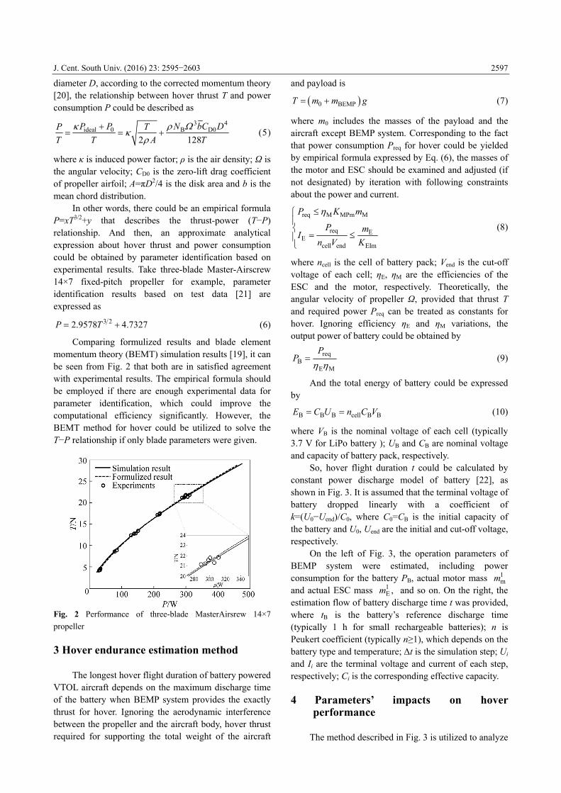
In other words, there could be an empirical formula P=xT3/2+y that describes the thrust-power (T−P) relationship. And then, an approximate analytical expression about hover thrust and power consumption could be obtained by parameter identification based on experimental results. Take three-blade Master-Airscrew 14×7 fixed-pitch propeller for example, parameter identification results based on test data [21] are expressed as
3 22.9578 4.7327P T (6)
Comparing formulized results and blade element
momentum theory (BEMT) simulation results [19], it can be seen from Fig. 2 that both are in satisfied agreement with experimental results. The empirical formula should be employed if there are enough experimental data for parameter identification, which could improve the computational efficiency significantly. However, the BEMT method for hover could be utilized to solve the T−P relationship if only blade parameters were given.
Fig. 2 Performance of three-blade MasterAirsrew 14×7
propeller
3 Hover endurance estimation method
The longest hover flight duration of battery powered VTOL aircraft depends on the maximum discharge time of the battery when BEMP system provides the exactly thrust for hover. Ignoring the aerodynamic interference between the propeller and the aircraft body, hover thrust required for supporting the total weight of the aircraft
and payload is 0 BEMPT m m g (7)
where m0 includes the masses of the payload and the aircraft except BEMP system. Corresponding to the fact that power consumption Preq for hover could be yielded by empirical formula expressed by Eq. (6), the masses of the motor and ESC should be examined and adjusted (if not designated) by iteration with following constraints about the power and current.
req M MPm M
req EE
cell end EIm
P K m
P mI
n V K
(8)
where ncell is the cell of battery pack; Vend is the cut-off voltage of each cell; ηE, ηM are the efficiencies of the ESC and the motor, respectively. Theoretically, the angular velocity of propeller Ω, provided that thrust T and required power Preq can be treated as constants for hover. Ignoring efficiency ηE and ηM variations, the output power of battery could be obtained by
ME
reqB
PP (9)
And the total energy of battery could be expressed by
B B B cell B BE C U n C V (10)
where VB is the nominal voltage of each cell (typically 3.7 V for LiPo battery ); UB and CB are nominal voltage and capacity of battery pack, respectively.
So, hover flight duration t could be calculated by constant power discharge model of battery [22], as shown in Fig. 3. It is assumed that the terminal voltage of battery dropped linearly with a coefficient of k=(U0−Uend)/C0, where C0=CB is the initial capacity of the battery and U0, Uend are the initial and cut-off voltage, respectively.
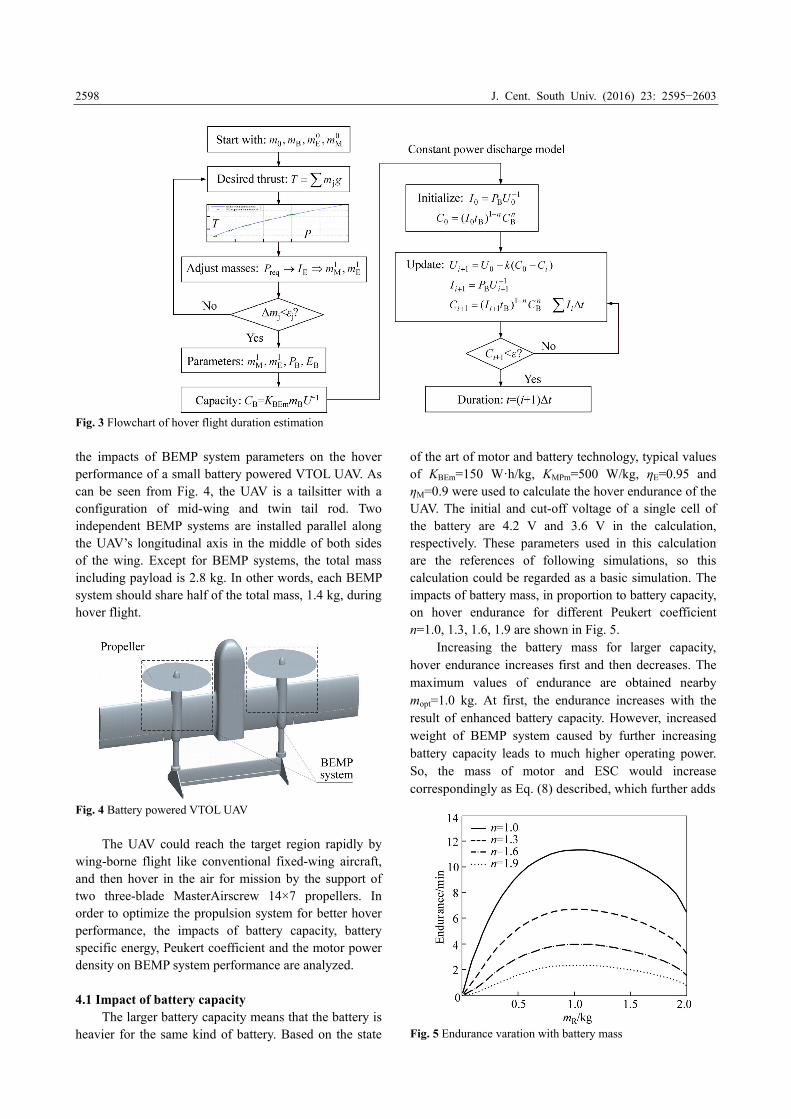
On the left of Fig. 3, the operation parameters of BEMP system were estimated, including power consumption for the battery PB, actual motor mass 1
mm and actual ESC mass 1
E ,m and so on. On the right, the estimation flow of battery discharge time t was provided, where tB is the battery’s reference discharge time (typically 1 h for small rechargeable batteries); n is Peukert coefficient (typically n≥1), which depends on the battery type and temperature; Δt is the simulation step; Ui and Ii are the terminal voltage and current of each step, respectively; Ci is the corresponding effective capacity. 4 Parameters’ impacts on hover
performance
The method described in Fig. 3 is utilized to analyze
J. Cent. South Univ. (2016) 23: 2595−2603
2598
Fig. 3 Flowchart of hover flight duration estimation
the impacts of BEMP system parameters on the hover performance of a small battery powered VTOL UAV. As can be seen from Fig. 4, the UAV is a tailsitter with a configuration of mid-wing and twin tail rod. Two independent BEMP systems are installed parallel along the UAV’s longitudinal axis in the middle of both sides of the wing. Except for BEMP systems, the total mass including payload is 2.8 kg. In other words, each BEMP system should share half of the total mass, 1.4 kg, during hover flight.
Fig. 4 Battery powered VTOL UAV
The UAV could reach the target region rapidly by
wing-borne flight like conventional fixed-wing aircraft, and then hover in the air for mission by the support of two three-blade MasterAirscrew 14×7 propellers. In order to optimize the propulsion system for better hover performance, the impacts of battery capacity, battery specific energy, Peukert coefficient and the motor power density on BEMP system performance are analyzed. 4.1 Impact of battery capacity
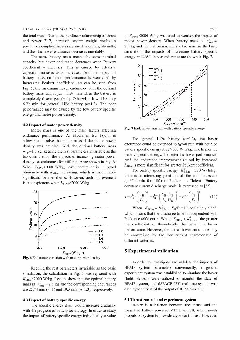
The larger battery capacity means that the battery is heavier for the same kind of battery. Based on the state
of the art of motor and battery technology, typical values of KBEm=150 W·h/kg, KMPm=500 W/kg, ηE=0.95 and ηM=0.9 were used to calculate the hover endurance of the UAV. The initial and cut-off voltage of a single cell of the battery are 4.2 V and 3.6 V in the calculation, respectively. These parameters used in this calculation are the references of following simulations, so this calculation could be regarded as a basic simulation. The impacts of battery mass, in proportion to battery capacity, on hover endurance for different Peukert coefficient n=1.0, 1.3, 1.6, 1.9 are shown in Fig. 5.
Increasing the battery mass for larger capacity, hover endurance increases first and then decreases. The maximum values of endurance are obtained nearby mopt=1.0 kg. At first, the endurance increases with the result of enhanced battery capacity. However, increased weight of BEMP system caused by further increasing battery capacity leads to much higher operating power. So, the mass of motor and ESC would increase correspondingly as Eq. (8) described, which further adds
Fig. 5 Endurance varation with battery mass
J. Cent. South Univ. (2016) 23: 2595−2603
2599
the total mass. Due to the nonlinear relationship of thrust and power T−P, increased system weight results in power consumption increasing much more significantly, and then the hover endurance decreases inevitably.
The same battery mass means the same nominal capacity but hover endurance decreases when Peukert coefficient n increases. This is caused by effective capacity decreases as n increases. And the impact of battery mass on hover performance is weakened by increasing Peukert coefficient. As can be seen from Fig. 5, the maximum hover endurance with the optimal battery mass mopt is just 11.34 min when the battery is completely discharged (n=1). Otherwise, it will be only 6.72 min for general LiPo battery (n=1.3). The poor performance may be caused by the low battery specific energy and motor power density. 4.2 Impact of motor power density
Motor mass is one of the main factors affecting endurance performance. As shown in Eq. (8), it is allowable to halve the motor mass if the motor power density was doubled. With the optimal battery mass mopt=1.0 kg, keeping the rest parameters invariable as the basic simulation, the impacts of increasing motor power density on endurance for different n are shown in Fig. 6. When KMPm<1000 W/kg, hover endurance is improved obviously with KMPm increasing, which is much more significant for a smaller n. However, such improvement is inconspicuous when KMPm>2000 W/kg.
Fig. 6 Endurance variation with motor power density
Keeping the rest parameters invariable as the basic
simulation, the calculation in Fig. 3 was repeated with KMPm>2000 W/kg. Results show that the optimal battery mass is opt 2.3m kg and the corresponding endurances are 25.74 min (n=1) and 19.5 min (n=1.3), respectively. 4.3 Impact of battery specific energy
The specific energy KBEm would increase gradually with the progress of battery technology. In order to study the impact of battery specific energy individually, a value
of KMPm>2000 W/kg was used to weaken the impact of motor power density. When battery mass is optm 2.3 kg and the rest parameters are the same as the basic simulation, the impacts of increasing battery specific energy on UAV’s hover endurance are shown in Fig. 7.
Fig. 7 Endurance variation with battery specific energy
For general LiPo battery (n=1.3), the hover endurance could be extended to tB=48 min with doubled battery specific energy KBEm>300 W·h/kg. The higher the battery specific energy, the better the hover performance. And the endurance improvement caused by increased KBEm is more significant for greater Peukert coefficient.
For battery specific energy 0BEm 380 W h/kg,K
there is an interesting point that all the endurances are tC=65.4 min for different Peukert coefficients. Battery constant current discharge model is expressed as [22]:
1 1 1B B B BB B B
B B B B
n n nn n nC C U E
t t t tI I U P
(11)
When 0
BEm BEm ,K K EB/PB=1 h could be yielded, which means that the discharge time is independent with Peukert coefficient n. When 0
BEm BEm ,K K the greater the coefficient n, theoretically the better the hover performance. However, the actual hover endurance may be constrained by the low current characteristic of different batteries. 5 Experimental validation
In order to investigate and validate the impacts of BEMP system parameters conveniently, a ground experiment system was established to simulate the hover flight. Sensors were utilized to monitor the state of BEMP system, and dSPACE [23] real-time system was employed to control the output of BEMP system. 5.1 Thrust control and experiment system
Hover is a balance between the thrust and the weight of battery powered VTOL aircraft, which needs propulsion system to provide a constant thrust. However,

J. Cent. South Univ. (2016) 23: 2595−2603
2600
the battery terminal voltage will drop gradually in actual discharge process. The speed of motor and propeller will decrease when pulse width of driven signal is constant, which leads to the unwilling fact of thrust decrease. Therefore, the thrust of BEMP system should be controlled for hover simulation.
According to the control mechanism of ESC, there is a relationship [10] between ESC output voltage (armature voltage of the motor) UESC and battery voltage UB, which can be expressed as
ESC BU f L U (12)
where f(L) is a function of PWM signal pulse width L. Serial tests were carried out to examine the function of a Phoenix ICE75 ESC. The phase voltage (percent of input voltage) in response to pulse width is given in Fig. 8.
Fig. 8 Phase voltage as a function of pulse width
Based on the experimental results, a third-order
polynomial regression gives an empirical formula of the function as
3 24.24 21.22 35.34 18.9f L L L L (13)
Assume that transferred torque between the motor
and the propeller is Q, without loss, then the dynamic models of motor and propeller could be expressed as
TM ESC V
2P
d
dd
d
Q
KJ U K Q
t R
J Q Kt
(14)
where ω is the motor speed; JP and JM are the inertias of the propeller and the motor, respectively; KT and KV are the torque and voltage constants of motor, respectively; R and λ are the resistance and the viscous drag coefficient of motor, respectively; KQ is the aerodynamic torque coefficient of the propeller.
Generally, the propeller is directly mounted on the motor shaft and directly driven by the motor, which means synchronized operation. Substituting Ω=ω, dΩ/dt=dω/dt and Eq. (12) into Eq. (14) yields system
dynamical equation:
2 T VP M
d
d QK K
J J Kt R
T BK Uf L
R (15)
The relationship between the hover thrust T and the
angular velocity of propeller Ω is 2
PT K (16)
where KP is a function of propeller parameters which could be obtained by experiments or estimation. For the employed three-blade MasterAirscrew 14×7 propeller, the value is KP=5.4115×10⁻⁵ N·s2/rad2.
The controller for the dynamic system described by Eq. (15) is generally realized by angular velocity feedback. In order to keep the thrust of the BEMP system to the expected value, a thrust feedback control method is employed. The framework of thrust observation and control is shown in Fig. 9.
Fig. 9 Framework of thrust control
Based on dSPACE rapid control prototyping system,
a ground experiment platform was established as shown in Fig. 10. The sensors, including thrust measuring instruments and an EagleTree flight recorder, are responsible for collecting the data of thrust, motor speed, terminal voltage and current of the battery. The control system consists of a host computer, a DS1103 PPC controller board and an I/O board. A PID controller is introduced to generate PWM signal in response to the thrust deviation ΔT=Treq−T, while the required thrust Ireq is obtained by Eq. (7).
Such experimental solution based on dSPACE system is low-cost, time-saving and easy to use. ControlDesk software system could be operated
Fig. 10 Hover performance evaluation platform

J. Cent. South Univ. (2016) 23: 2595−2603
2601
conveniently for state monitoring, real-time data acquisition and parameter adjustment. 5.2 Experimental results
The ground experiment platform was used to validate the impacts of the battery specific energy and the motor power density on the hover performance of the UAV presented in Fig. 4. A Scorpion S4020-14 BLDC motor, a Phoenix ICE75 ESC and a three-blade MasterAirsrew 14×7 propeller constitute two sets of BEMP system with fully charged AKE 6S-6Ah and 6S-10Ah LiPo battery. The masses of the motor, the propeller and the ESC are 0.345 kg, 0.078 kg and 0.095 kg, respectively.
Considering the mass break down of each BEMP system, m0=1.4 kg, thrust required for hover was calculated and corresponding power consumption was yielded by Eq. (6). Parameters of BEMP systems used in following experiments are listed in Table 1. Table 1 Parameters of BEMP systems
System mB/kg KBEm/(W·h·kg) Treq/N KMPm/(W·g−1)
6A·h-BEMP 0.866 154 27.3 1.37
10A·h-BEMP 1.392 160 32.5 1.78
Experiments were carried out for each BEMP
system with parameter adjustments of the controller. Actual thrusts in the beginnings are shown in Fig. 11, while the entire experiments last much longer. For step target thrust, Fig. 11 shows the step response and steady- state error. Although the response time lasts almost 10 s for each test, it is still tolerable for the entire discharge process lasts almost thousand minutes. Thrust fluctuation for each test is within a range of |ΔT|<0.4 N.
The terminal voltage drop of each battery is shown in Fig. 12. The voltage suddenly drops about 0.5 V at the beginning, and then decreases approximately linearly until the average voltage of single cell reaches the level of 3.6 V. After that, the battery voltage drops rapidly as the battery is almost completely depleted. When
Fig. 11 Actual and expected thrust at beginning
Fig. 12 Terminal voltage variation with discharge time
discharge stops, the voltage of each battery recovers more or less, where t1 and t2 are the discharge time corresponding to cut-off voltage Uend=21.6 V, respectively; t3 and t4 are the maximum discharge time before battery collapse, respectively.
The discharge current of each battery is shown in Fig. 13. Due to constant power load, the discharge current increases gradually as the battery voltage decreases, and such increase accelerates as the discharge is nearly completed. The actual discharge rates of 6 A·h and 10 A·h battery are in the ranges of 3C−4C, 2.5C− 3.2C, respectively. There is slight current fluctuation caused by the load disturbance, as described in Fig. 11.
Fig. 13 Current variation with discharge time
The angular velocity of the motor and the total
power consumption are shown in Fig. 14. The average motor speed and corresponding power consumption for 6 A·h BEMP system are 6431 r/min and 465 W, respectively; while those for 10 A·h BEMP system are 7116 r/min and 646 W, respectively. The power fluctuations are in the range of <30 W, and the values of motor speed fluctuation are in the range of <103.
Compared with the experimental results, the simulation results for different mB and KMPm are shown in Fig. 15, with the parameters: ηM=0.9, ηE=0.95, n=1.3,

J. Cent. South Univ. (2016) 23: 2595−2603
2602
Fig. 14 Motor speed and power consumption with discharge
time
Fig. 15 Comparison simulation data with experimental results
KBEm=160 W·h/kg, U0=25.2 V, Uend=21.6 V. The numerical endurances as KMPm=1.3, 1.8 W/g match well with the experimental results.
The agreements validate the model of BEMP system and hover flight duration estimation method. Parameter errors, including ΔηM, ΔηE, Δn, ΔKBEm, ΔKMPm, have been inevitably introduced to the endurance calculation. The constant power discharge model and voltage drop model of LiPo battery should be improved for more precisely estimation in the future research. 6 Conclusions
A model of BEMP system has been presented with
system weight and power consumption considerations. A precise method to estimate the hover endurance of battery powered VTOL aircraft has been established according to a linear voltage drop model. For an uncompleted battery powered VTOL UAV, the impacts of the main parameters of BEMP system on hover performance have been analyzed by simulation and validated by experiments.
1) The results show that the hover performance of battery powered VTOL aircraft is quite related with BEMP system parameters e.g. KBEM, n, mB and KMPm. Particularly, KBEm is the main factor that determines the hover performance, endurance increasing with higher specific energy. n determines the effective capacity, and the battery with smaller n should be selected for better hover performance at present. Low level of KMPm may limit the hover performance obviously. There is an optimal battery mass selection mB=mopt for the maximum hover endurance.
2) For the state of the art of battery, a maximum hover flight duration about 20 min could be achieved for the heavy-duty (mpayload>1 kg) battery powered VTOL UAV. However, the battery and the BEMP system share 42.05%, 57.7% of the total weight of the UAV, respectively. Such UAV is expected to accomplish more than hour’s hover flight mission if the battery specific energy was higher than 350 W·h/kg.
3) Based on the model and method described, multi-disciplinary optimization design for BEMP system should be carried out to improve the hover flight duration. Better performance of propeller consuming less power for the same hover thrust is recommended. Acknowledgments
The authors want to appreciate the editors and reviewers for their hard work and valuable suggestions. References
[1] MICHAEL N, SHEN S, MOHTA K. Collaborative mapping of an
earthquake-damaged building via ground and aerial robots [J].
Journal of Field Robotics, 2012, 29(5): 832−841.
[2] Drones deployed in quake relief. [2014−10−05]. http://www.
chinadaily.com.cn/china/2014-08/05/content_18252904.htm.
[3] NASA Long-Lived Mars Opportunity Sets Off-World Driving record
[2014−10−05]. http://www.mars.nasa.gov/mer/newsroom/ressreleases/
20140728a.html.
[4] Curiosity makes its longest one-day drive on Mars [OL].
[2014−12−05]. http://www.mars.jpl.nasa.gov/news/whatsnew/index.
cfm?FuseAction= ShowNews&NewsID=1498.html.
[5] YOUNG LARRY A, AIKEN EDWIN W. Vertical lift planetary aerial
vehicles: Three planetary bodies and four conceptual design cases
[C]// 27th European Rotorcraft Forum. Moscow: ERF, 2001: 11−14.
[6] YOUNG L A, PISANICH G, BRIGGS G, AIKEN E. Rotary wing
decelerators for probe descent through the atmosphere of Venus [R].
Moffett Field: NASA Ames Research Center, 2004: 209−215.
[7] ZHAO W, UNDERWOOD C. Robust transition control of a Martian

J. Cent. South Univ. (2016) 23: 2595−2603
2603
coaxial tilt rotor aerobot [J]. Acta Astronautica, 2014, 99: 111−129.
[8] LANGELAAN J W, ROY N. Enabling new missions for robotic
aircraft [J]. Science, 2009, 326(326): 1642−1644.
[9] AscTec Pelican [OL]. [2014−10−05]. http://www.asctec.de/en/uav-
uas-drone-products/AscTec Pelican/Details.
[10] STEPANIAK M J, van GRAAS F, HAAG M U. Design of an electric
propulsion system for a quadrotor unmanned aerial vehicle [J].
Journal of Aircraft, 2009, 46(3): 1050−1058.
[11] HOGGE J V. Development of a miniature VTOL tailsitter [D]. Provo:
Brigham Young University, 2008.
[12] Draganflyer X8 helicopter tech specs [OL]. [2014−10−05].
http://www.draganfly.com/uav-helicopter/draganflyer-x8/specificatio
ns.php.
[13] MOSCHETTA J, BATAILLÉ B, THIPYOPAS C, SHKARAYEV S.
On fixed-wing micro-air vehicles with hovering capabilities [C]//
46th AIAA Aerospace Sciences Meeting and Exhibit. Reno, Nevada,
2008: 1−13.
[14] HOFFMANN G M, WASLANDER S L, VITUS M P. Stanford
testbed of autonomous rotorcraft for multi-agent control [C]// The
2009 IEEE/RSJ International Conference on Intelligent Robots and
Systems. St. Louis, USA: IEEE, 2009: 404−405.
[15] BINETTI P, TROUCHET D, POLLINI L, INNOCENTI M. The
flight control system of the hovereye VTOL UAV [R].
Neuilly-sur-Seine, France: Bertin Technologies, 2007.
[16] NG T T H, LENG G S B. Design of small-scale quadrotor unmanned
air vehicles using genetic algorithms [J]. Proc IMechE, Part G:
Journal of Aerospace Engineering, 2007, 221(5): 893−905.
[17] WANG Xin-hua, LIN Hai. Design and control for rotor-fixed wing
hybrid aircraft [J]. Proceedings of the Institution of Mechanical
Engineers, Part G: Journal of Aerospace Engineering, 2011, 227(10):
1556− 1570.
[18] GUR O, ROSEN A. Optimizing electric propulsion systems for
unmanned aerial vehicles [J]. Journal of Aircraft, 2009, 46(4):
1340−1353.
[19] BO W, HOU Z, WANG W. Performance of propulsion system of
miniature electric-powered vertical takeoff and landing air vehicles
[J]. Journal of National University of Defense Technology, 2015,
37(3): 84−90.
[20] LEISHMAN J G. Principles of helicopter aerodynamics [M]. 2nd
edition. New York: Cambridge University Press, 2006.
[21] RADHAKRISHNAN A. An experimental investigation of ground
effect on a quad tilt rotor in hover and low speed forward flight [D].
Maryland: University of Maryland, 2006.
[22] TRAUB L W. Range and endurance estimates for battery powered
aircraft [J]. Journal of Aircraft, 2011, 48(2): 703−708.
[23] dSPACE-DS1103 PPC controller board [OL]. [2014−10−05].
http://www. dspace.com/.
(Edited by YANG Hua)