Embed Size (px)
Citation preview

How Can I Minimize Water
Loss and Pipe Breaks in my
Water Distribution System?
Presented by Jim Graber
Background
leakage
Reported
breaks
Unreported
breaks
Three Common Causes of Water Loss

The higher the pressure,
the greater the loss
Background leakage can add up to significant water loss over time
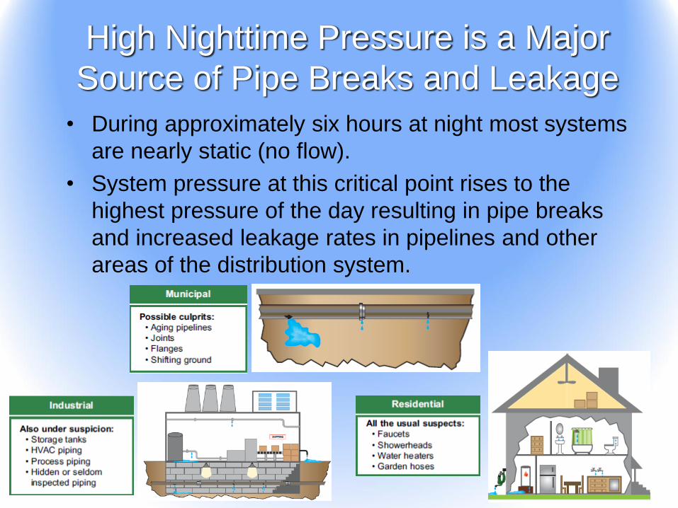
High Nighttime Pressure is a Major
Source of Pipe Breaks and Leakage
• During approximately six hours at night most systems
are nearly static (no flow).
• System pressure at this critical point rises to the
highest pressure of the day resulting in pipe breaks
and increased leakage rates in pipelines and other
areas of the distribution system.

Large diameter
pipe breaks
16” and larger
$10,000
Water main
breaks
6” to 16”
$4,000
Hydrant and
valve breaks
$2,000
Service line
breaks
1/2” to 2”
$1,500
Average per occurrence cost
Pipe Breaks are Expensive
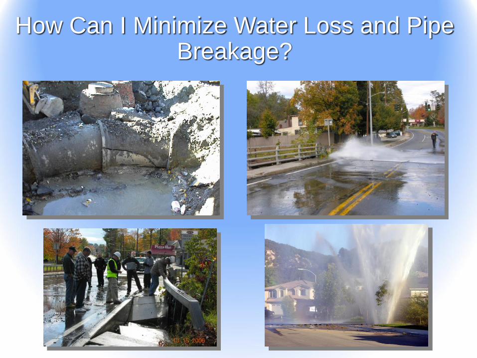
How Can I Minimize Water Loss and Pipe Breakage?
Actions for Leakage Abatement
• Replace the complete leaking system - to
practically eliminate leakage
• Use multiple feeds - to minimize line loss
which allows a lower system pressure
• Use advanced valve control schemes - to
effectively deal with line loss

Replace Leaking System
• Most expensive solution
• Practically eliminates leakage
• Logistically it is very difficult
• Most difficult solution for existing
customers

Multiple Feed System
• Minimizes line loss
• Reduces velocities in the system
• Lower cost than replacing the system
• Less intrusive to customers than replacing
the system
Advanced Valve Controls
• Quickest Solution
• Lowest cost solution
• Least intrusive to existing customers
• May be retrofitted to existing valve
• Keeps pressure low when high pressure is
not required
• Allows high pressure for fire flow
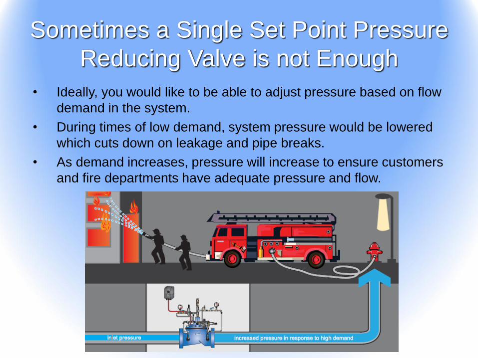
Sometimes a Single Set Point Pressure
Reducing Valve is not Enough
• Ideally, you would like to be able to adjust pressure based on flow
demand in the system.
• During times of low demand, system pressure would be lowered
which cuts down on leakage and pipe breaks.
• As demand increases, pressure will increase to ensure customers
and fire departments have adequate pressure and flow.
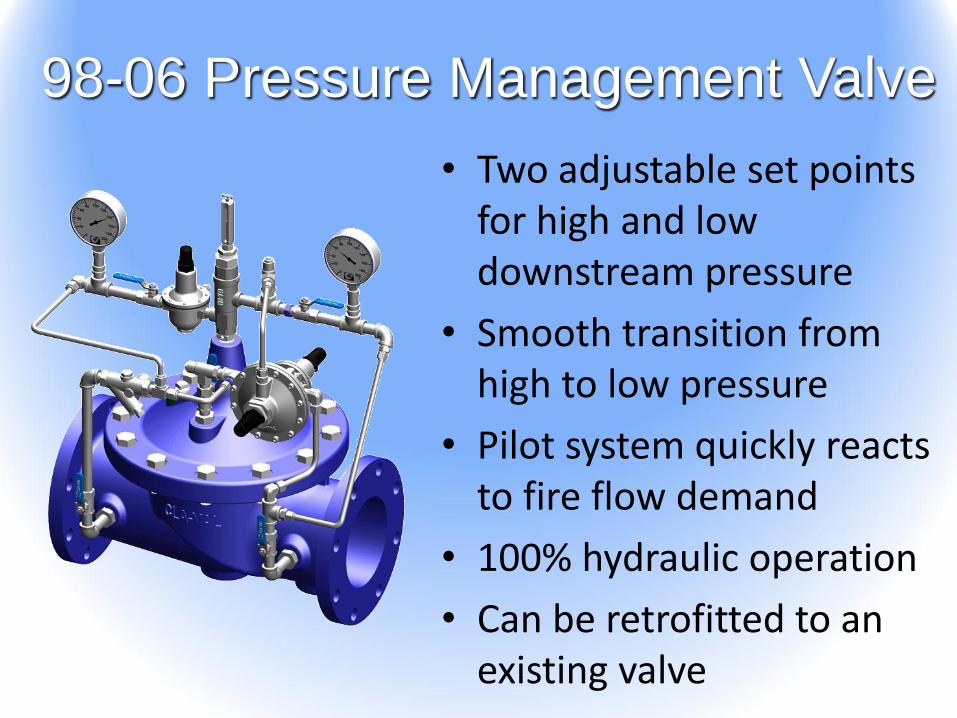
98-06 Pressure Management Valve
• Two adjustable set points for high and low downstream pressure
• Smooth transition from high to low pressure
• Pilot system quickly reacts to fire flow demand
• 100% hydraulic operation
• Can be retrofitted to an existing valve
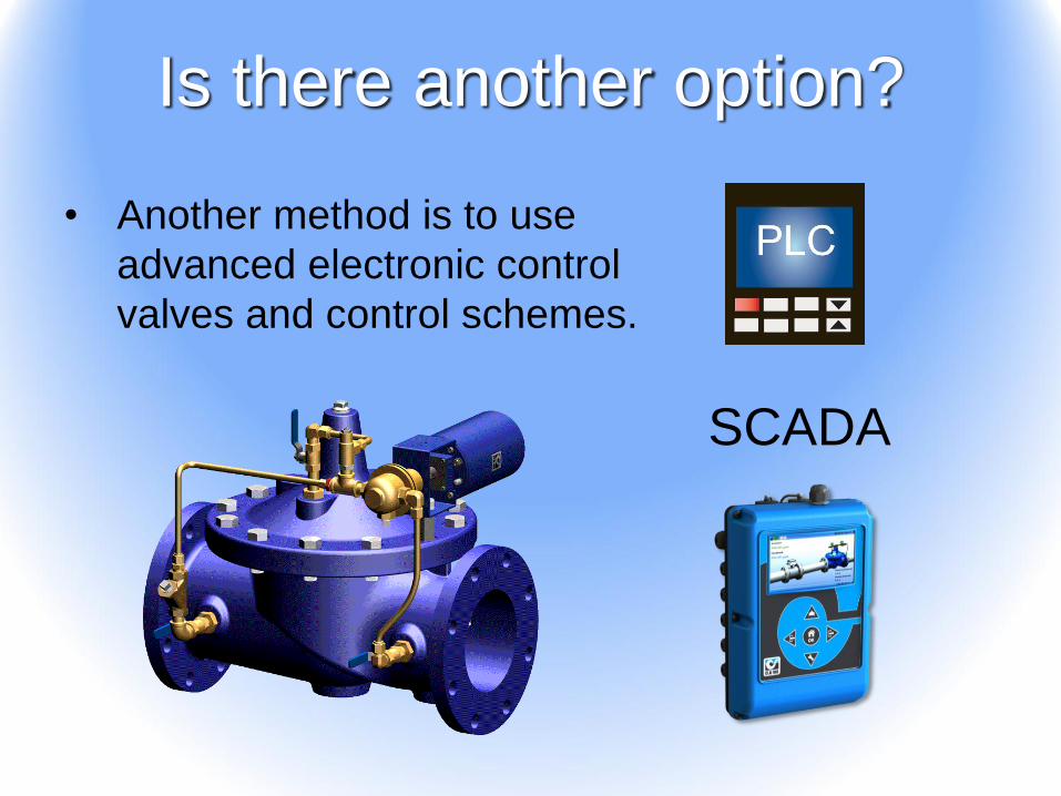
Is there another option?
• Another method is to use
advanced electronic control
valves and control schemes.
SCADA

Electronic Measurement Devices

What Kind of Information Can I Get
From A Control Valve?
• Is the valve open or closed?
• How far open is the valve?
• What is my pressure upstream and/or
downstream of the valve?
• What is the pressure differential /
pressure drop across the valve?
• How much flow is going through the
valve?

Limit Switches
• Function: Provide a digital signal through an electrical
contact when the valve is in a specific position.
• Available in single or multiple switches
• Tied to the movement of the valve by a stem extension
piece with stop collar(s) to actuate switch

Limit Switches
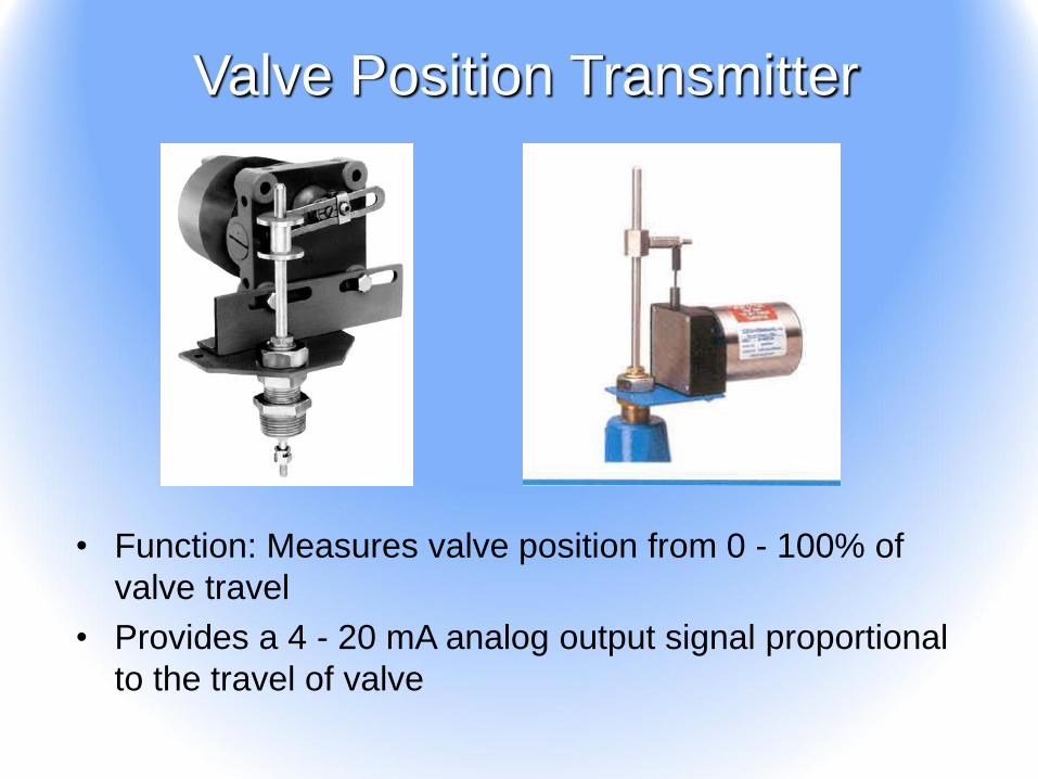
• Function: Measures valve position from 0 - 100% of
valve travel
• Provides a 4 - 20 mA analog output signal proportional
to the travel of valve
Valve Position Transmitter

Valve Position Transmitter
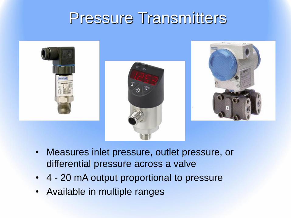
• Measures inlet pressure, outlet pressure, or
differential pressure across a valve
• 4 - 20 mA output proportional to pressure
• Available in multiple ranges
Pressure Transmitters
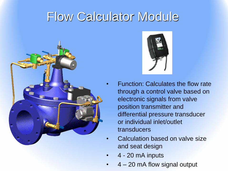
• Function: Calculates the flow rate
through a control valve based on
electronic signals from valve
position transmitter and
differential pressure transducer
or individual inlet/outlet
transducers
• Calculation based on valve size
and seat design
• 4 - 20 mA inputs
• 4 – 20 mA flow signal output
Flow Calculator Module

• This meter is designed to be inserted on the inlet side of a control valve
• Provides a 4-20 mA signal that is proportional to flow rate
• Typical accuracy of +/- 2% of full scale –used for information or control of valve
• Can be retrofitted to an existing control valve
• There are restrictions on upstream piping and isolation valve configuration with this type of meter
Insertion Flow Meter

Electronic Control Valves

Hydraulic Valve with Motorized Pilots
Pressure Reducing Rate of Flow /
Differential Pressure
Pressure Relief
Motor Actuator
• Allows remote pressure/flow
rate changes
• 4-20 mA input
• Pre-calibrated – no field
calibration required
• Multiple adjustment ranges
available – can be re-scaled
within factory range
Hydraulic
Pilot

• Pilot system consists of
an opening and a closing
solenoid
• Remote analog and
digital signals are used to
tell valve what to do
• Solenoids are controlled
by a PLC, SCADA, or a
valve controller combined
with electronic feedback
signals to achieve many
different functions
• Can be paired with
hydraulic pilot controls to
perform multiple functions
or as backup in case of a
power failure
Dual Solenoid Control Valves
SCADA

How Do I Use These Valves to
Minimize Water Loss and Pipe Breaks?
• Electronics are used to monitor pressure, flow rate, and/or the time of day.
• These signals are fed into a control system, which may consist of PLC’s, a SCADA system, or a Cla-Val electronic valve controller.
• The control system uses these signals to determine when pressure needs to be adjusted and sends an electronic signal back to the valve.
• The electronic controls on the valve adjust the position of the valve to deliver the appropriate system pressure.

Pressure Optimization Control
Scheme
• During times of low demand or at night, system pressure is reduced.
• During times of high demand or during the day, system pressure is increased.
Flow Rate
Pre
ssure
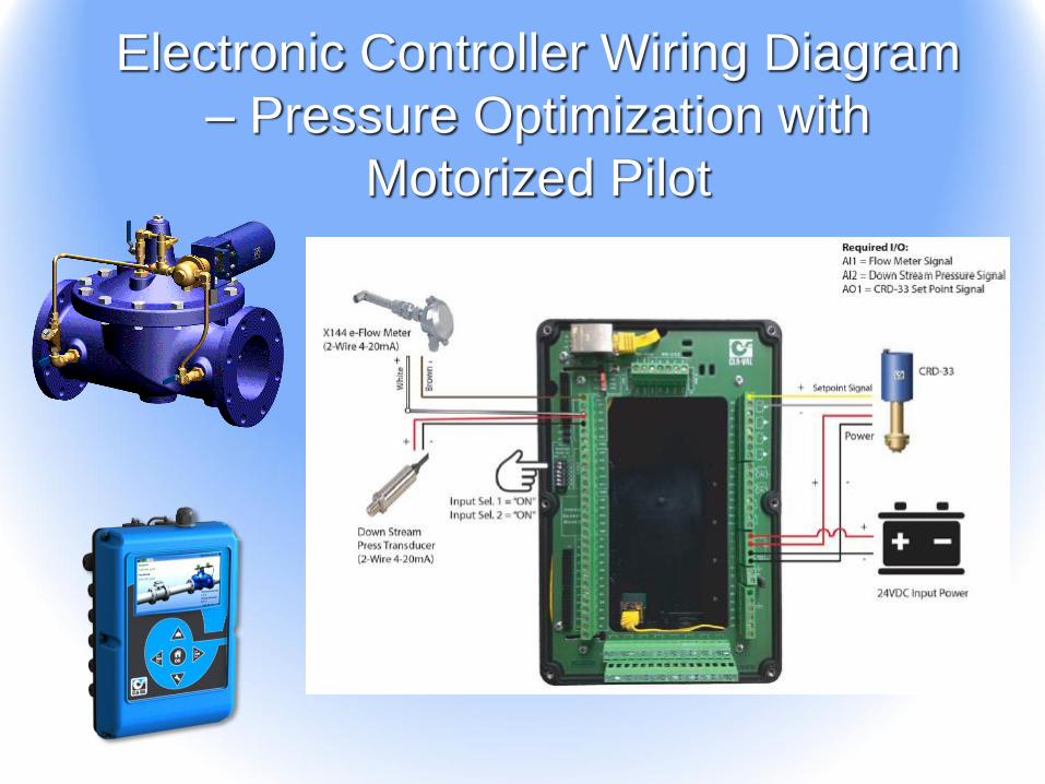
Electronic Controller Wiring Diagram
– Pressure Optimization with
Motorized Pilot
What are other ways
electronic measurement
devices and electronic
control valves can be
used to help save water,
time, and money?

Electronics Allow You to Adjust
Valves in Difficult Locations
• Remote
• Controlled
Space
• Hazardous
• Elevated
• Buried Vaults
• Manholes

Electronics can Trigger Alarms
• Valve limit switches can
trigger an alarm if a valve
opens or closes at the wrong
time.
• Pressure transducers can
indicate if pressure is too high
or too low.
• Flow meters can indicate if
flow goes above a maximum
rate or drops below a
minimum rate.

Electronics can Automatically
Adjust to Changing Conditions
• Electronic valve controllers
can be used to automatically
adjust flow or pressure
based on feedback signals
– They can be programmed to
adjust fill rates as tank levels
change.
– They can adjust pressure
based on flow rate, tank level,
or time of day.

What are some other
ways to minimize pipe
breaks and leakage?
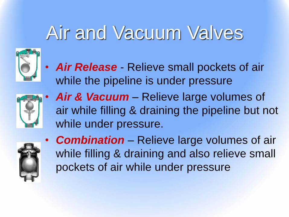
Air and Vacuum Valves
• Air Release - Relieve small pockets of air
while the pipeline is under pressure
• Air & Vacuum – Relieve large volumes of
air while filling & draining the pipeline but not
while under pressure.
• Combination – Relieve large volumes of air
while filling & draining and also relieve small
pockets of air while under pressure

Why Use Them?
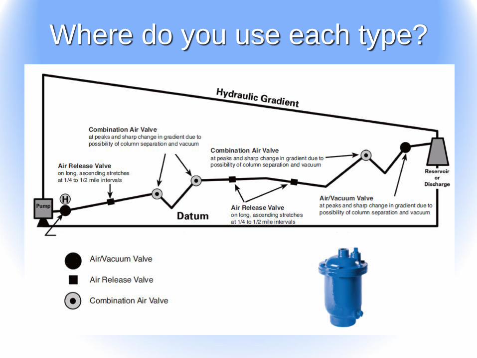
Where do you use each type?

Other Issues?• If air gets into the pilot system of a pressure
reducing valve, the valve will lose the ability to
regulate pressure, causing system pressure to
increase, resulting in pipe breaks and/or
increased leakage. An air release valve on
the cover of the valve can help prevent this.
• Vacuum valves ensure
pipelines do not enter into a
negative pressure situation
which can cause a pipeline to
collapse.

• Pressure Relief Valves are typically used on the
discharge piping of a booster pump station. They are
designed to open when inlet pressure goes above the
pilot setting to relieve pressure surges in piping systems.
Pressure Relief Valves
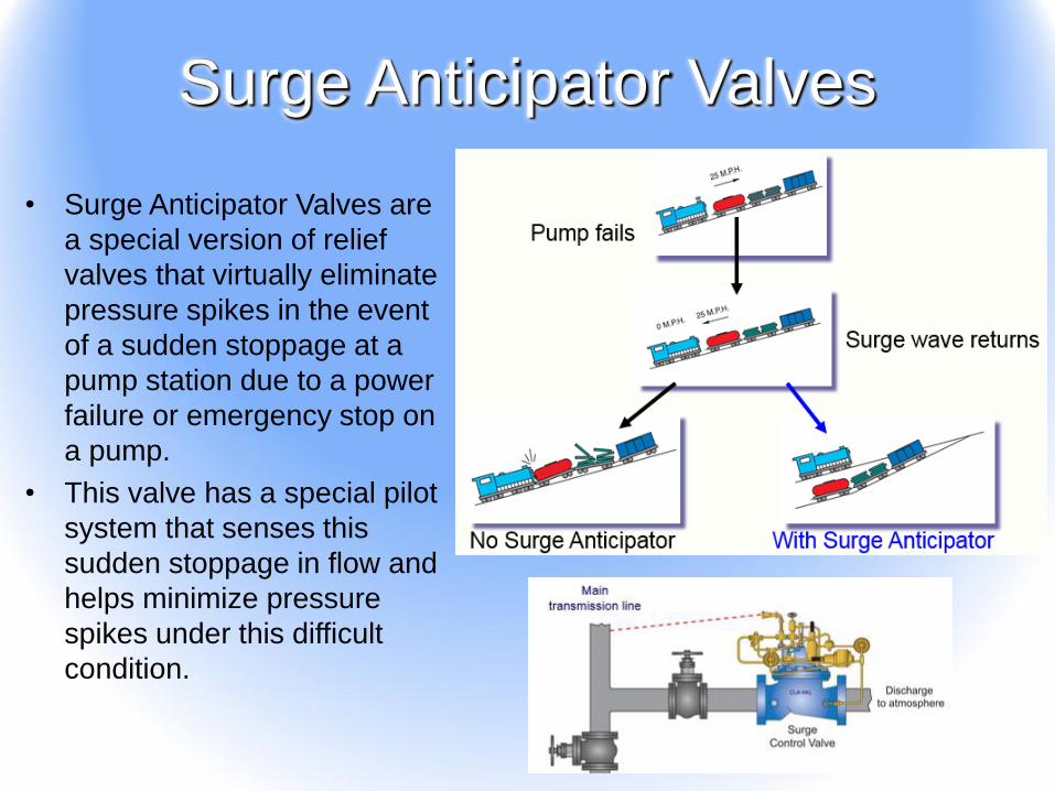
• Surge Anticipator Valves are
a special version of relief
valves that virtually eliminate
pressure spikes in the event
of a sudden stoppage at a
pump station due to a power
failure or emergency stop on
a pump.
• This valve has a special pilot
system that senses this
sudden stoppage in flow and
helps minimize pressure
spikes under this difficult
condition.
Surge Anticipator Valves

• When there is a sudden
stoppage in flow, pressure in
the pipeline will drop below
normal static pressure. The
valve has a low pressure
pilot that senses this drop
and opens the valve. Some
valves have a flow limiting
device to limit the amount
the valve opens. When the
pressure wave comes back,
the water exits through the
open valve, which virtually
eliminates any spike in
pressure.
How Do They Work?

• When using a surge anticipator
valve, you need to ensure there is
a source of static pressure in your
distribution system that will give
pressure at the inlet of the valve
when all pumps are off. Typically,
this means there is a water tower
downstream of the pump station.
Are There Any Limitations?

Questions?
Jim Graber
Cla-Val Area Sales Manager
Indiana, Michigan, and Ohio
Office: (330) 952-0860
Cell: (440) 523-0496
E-Mail: [email protected]