Embed Size (px)
Citation preview

EY-RC 502: Room automation station, ecos502
How energy efficiency is improvedPowerful function modules in the ecos allow energy-optimised room control and the control of lightsand blinds and guarantee minimum energy consumption
Features• Part of the SAUTER EY-modulo 5 system family• Communication: BACnet/IP (EN ISO 16484-5)• Programming/parameterisation via PC using CASE Suite (based on IEC 61131-3)• Integration into the building management system via Ethernet/BACnet/IP data interface• Room automation station for up to two rooms or room segments• Free arrangement of hardware• The ecoUnit 3 (EY-RU 3**) and ecoUnit 1 (EY-RU 1**) room operating units enable individual ad-
justment of the room climate – mixed mode is possible• Optimises energy consumption thanks to occupancy function, window contact monitoring, needs-
driven switching of fan speeds, control of lighting and window blinds, and time-dependent setpointspecification
• Time and calendar function• Control libraries
Technical data
Power supplyPower supply 230 V~, ±10%, 50...60 HzPower consumption ≤ 34 VA (incl. 12 VA external)Power loss ≤ 15 WBattery (buffer: RTC/SRAM) Lithium button-cell (CR2032), inserta-
ble
Ambient conditionsOperating temperature 0...45 °CStorage and transport temperature –25...70 °CHumidity 10...85% rh, no condensation
Inputs/OutputsInputs Universal inputs 8, Ni1000, Pt1000, 0...10 V, DI
Digital inputs 4Outputs Relay outputs 16 NO contacts (250 V~)
Terminals 1 to 24 2 commutating pole circuit (24 V=) Terminals 25 to 28
Triac 8 (24 V~)Analogue 4 (0...10 V)
FunctionBACnet data point objects 256 incl. HW
Number of dynamic objects Time programmes 32 (Schedule)Calendar 8 (Calendar)Alarms 16 (Notification Class)Historical data 16 (Trend Log)
≤ 2000 entriesControl 32 (Loop)COV notifications 500Structured view 64 (Structured View)Number of BACnet client links 200 (Peer-to-Peer)BBMD in BDT 32FD in FDT 32
ArchitectureProcessor 32 bit, 200 MHzSDRAM (synchronous dynamic RAM) 32 MBSRAM (static RAM) 128 kB
Product data sheet 94.110
Right of amendment reserved © 2015 Fr. Sauter AG 5.1 1/14
EY-RC502F001

Flash 16 MBOperating system LinuxCycle time, user program 100 msApplication data via CASE Engine
Interfaces and communicationEthernet network 2 × RJ-45 socket (switch)10/100 BASE-T(X) 10/100 Mbit/sCommunication protocols BACnet/IPOperating units Total of up to four operating unitsEY-RU 3** RS-485 AEY-RU 1** via EY-EM 580 to RS-485 A
ConstructionFitting top-hat rail/wallDimensions W x H x D 299 × 120 × 73 mmWeight 1.6 kg
Standards and directivesType of protection1) IP 00 (EN 60529)Protection class I (EN 60730-1)Energy class2) I to VIII = up to 5 %
acc. EU 811/2013, 2010/30/EU,2009/125/EG
Environment class 3K3 (IEC 60721)CE conformity according to EMC directive 2004/108/EC3) EN 61000-6-1, EN 61000-6-2,
EN 61000-6-3, EN 61000-6-4Low-voltage directive 2006/95/EC EN 60730-1, EN 60730-2-9Software class A EN 60730-1 Annexe H
Valid for eu.bac. devices EY-RC502F511, EY-RC502F521
Energy Performance of BuildingsDirective 2010/31/EC
EN 15500
eu.bac licence no. 211168
Overview of typesType Properties
EY-RC502F001 Room automation station
EY-RC502F521 Room automation station with screw terminals, eu.bac application for chilled-beam system
EY-RC502F511 Room automation station with screw terminals, eu.bac application for fan convection system – 4-pipe
A On the EY-RC502F5** versions, it is not permitted to make any changes to the user program that have aninfluence on the control quality, otherwise the eu.bac certificate loses its validity.
AccessoriesType Description
0900240002 Terminal cover, 295 mm (2 pcs.)
0900240011 Wiring box, 295 mm (2 pcs.)
Description of operationThe ecos502 room automation station is a compact unit for energy-optimised room control by meansof demand-controlled fan speed switching, window contact monitoring and the control of lights andblinds. This allows an individual room climate to be attained with minimum energy consumption.The ecos 5 system family comprises a range of devices for room automation for the BACnet/IP sys-tem bus. The ecos502 is a freely programmable BACnet Building Controller (B-BC) for the automationof up to 2 rooms with the functions room climate, lighting and sunshade. The powerful programmingenvironment CASE Suite and the available function libraries allow both standard tasks of room auto-mation and complex projects with flexible room division, based on room segments, to be carried outefficiently.
1) IP 10 with terminal cover (accessory 090024002); IP 20 with wiring box (accessory 090024011)2) When controlling the temperature using the automation station, the requirements can be fulfilled for most tem-
perature control classes according to Regulation 811/2013 (EU) supplementing EU Directive 2010/30/EU. Forinformation on the exact temperature class, please refer to the system integrator's user program.
3) If it is mandatory to comply with the European Standard (EN 61000-6-2), the connecting cables for the digitalinputs (DI), analogue inputs and outputs (AI/AO) and the RS-485 cables must not be longer than 30 metres
Product data sheet 94.110
2/14 5.1 Right of amendment reserved © 2015 Fr. Sauter AG

The ecos502 has a total of 40 inputs and outputs. Using an RS485 interface, ecoUnit 3 room operat-ing units and an ecoMod580 EnOcean wireless interface can be connected. The wireless interfacecan be used to integrate the SAUTER ecoUnit 1 wireless room operating units as well as other stand-ard EnOcean units.The room automation station is based entirely on BACnet/IP communication.
Intended useThis product is only suitable for the purpose intended by the manufacturer, as described in the “De-scription of operation” section.All related product regulations must also be adhered to. Changing or converting the product is not ad-missible.
EY-RC502F511 with the eu.bac application “fan coil unit system – 4-pipe”
Key figures of eu.bac certificationMode Control accuracyHeating approx. 0.2 KCooling approx. 0.3 K
The application has been certified with the following devices:Type Quantity DescriptionEY-RC502F511 1 Room automation station with screw terminalEY-RU346F001 1 ecos 5 operating unit, LCD, NTC sensor, dXs setpoint adjuster, 6 buttonsAXS215SF122 2 Continuous actuator for unit valves with stroke indicatorVCL025F200 2 2-way regulating valve (linear)
EY-RC502F521 with the eu.bac application “chilled-ceiling system”
Key figures of eu.bac certificationMode Control accuracyCooling approx. 0.1 K
The application has been certified with the following devices:Type Quantity DescriptionEY-RC502F521 1 Room automation station with screw terminalEY-RU346F001 1 ecos 5 operating unit, LCD, NTC sensor, dXs setpoint adjuster, 6 buttonsAXS215SF122 1 Continuous actuator for unit valves with stroke indicatorVCL025F200 1 2-way regulating valve (linear)
Engineering notesThe I/O mix of the ecos502 is designed typically for 2 rooms or room segments, i.e. 2 room controllersare integrated in one device. During programming, a program is created that applies equally to bothrooms/room segments. The possible number of segments is 1 or 2.
Fitting and power supplyThe ecos502 is a compact unit, suitable for wall mounting or for DIN 43880 installation on a 35 mmtop-hat rail. The plant devices are connected using screw terminals. The following conditions must beobserved:• Connection may only be performed when the system is disconnected from the electrical supply.• The unit must be protected against contact.• The max. available power at the LS terminals is 12 VA.• The ground terminals are connected internally to the earth connection (PELV electrical circuits).• External primary isolating facility• Protective earth is connected to the relevant terminalCross-section of the wire: min. 0.8 mm² (AWG 18), max. 2.5 mm² (AWG 13), taking standards andnational installation regulations into account.For communication, there are two RJ-45 network connections with switch functionality that can beused to switch the ecos502s in a sequence. When establishing the network topology, the Ethernetnetwork standards are to be taken into account.The communication wiring must be carried out correctly and in accordance with the standardsEN 50174-1, -2 and -3. Communication wires must be kept at a distance from other live wires.
Product data sheet 94.110
Right of amendment reserved © 2015 Fr. Sauter AG 5.1 3/14

Special standards such as IEC/EN 61508, IEC/EN 61511, IEC/EN 61131-1 and -2 were not taken intoaccount. Local requirements regarding installation, usage, access, access rights, accident prevention,safety, dismantling and disposal must be taken into account. Furthermore, the installation standardsEN 50178, 50310, 50110, 50274, 61140 and similar must be observed.For further information, see the fitting instructions P100002325.
Wiring boxThe wiring box is used for professional connection of supply and control lines with a cord grip. Whenthe cover is in place, it provides the IP 20 degree of protection together with the ecos.
Wiring box
Wiring rulesThe feedback cables for the Ni1000 and Pt1000 sensors must be separated from the other inputs andoutputs (DI 1.2 mA, 0…20 mA), i.e. separate GND terminals (⊥) must be used.
Inputs and outputsThe ecos502 has 42 inputs and outputs with the following functionalities:
Universal inputsNumber of inputs 8 (UI)Type of inputs(software coding)
Ni1000 (DIN 43760)Pt1000 (EN 60751)Voltage measurement (U)Current measurement (I) (with external resistance)Resistance measurementDigital input (DI)
Protection against external voltageNi/Pt/U/DI
±30 V/24 V~ (without destruction)
Scan rate 100 ms (digital values)500 ms (analogue inputs)
Resolution > 14 bitsMeasuring rangesVoltage (U)
0 (2)...10 V, 0 (0.2)...1 V
Current (I) (via ext. R) 0 (4)...20 mAResistance 200…2500 ΩTemperatureNi/Pt1000
-50...+150 °C
Digital input Potential-free contacts with ground connectionopto-coupler, transistor (open collector)Iout:• ~1.2 mA for UI• ~1.2mA for DI
Meter Max. 3 Hz (100 ms scan rate)
Product data sheet 94.110
4/14 5.1 Right of amendment reserved © 2015 Fr. Sauter AG

Temperature measurement (Ni/Pt)The Ni/Pt1000 sensors are connected using two wires between one of the input terminals for univer-sal inputs (channel 26...33) and a ground terminal. The inputs require no calibration and can be useddirectly. Line resistance of 2 Ω is pre-compensated as standard. With the correct line resistance of 2Ω (cable cross-section 1.5 mm²), the power cable (wire) may be no more than 85 m. Larger line resis-tances can be compensated by the software. The measurement current is pulsed to ensure that thesensor is not heated (lmeas ~0.3 mA).
Voltage measurement (U)The voltage to be measured is connected between an input terminal for universal inputs (channel26...33) and a ground terminal. The signal must be potential-free. The measuring ranges with or with-out offset 0 (0,2)...1 V or 0 (2)...10 V are selected through the software. The internal resistance Ri ofthe input (load) is 9 MΩ.
Current measurement (I)A current measurement is possible via external resistance (e.g. 50 Ω). The current to be measured isconnected on one of the two input terminals for universal inputs (channel 26...33) and a ground termi-nal parallel to the resistance. The current signal must be potential-free.
Resistance measurementThe ecos502 can measure resistive loads between 200 and 2500 Ω. The measurement takes placewith respect to ground. Higher resistance values can be scaled to approx. 2500 Ω by parallel switch-ing of an additional fixed resistance. A linearisation may be needed in the user program.
Digital inputs (DI with UI)The ecos502 also records binary information with the universal inputs. The information (alarm/status)is connected between an input terminal and the ground (channel 26...33). The station applies a volt-age of approximately 13 V to the terminal. If a contact is open, this usually corresponds to an INAC-TIVE state (bit = 0). If a contact is closed, there is an ACTIVE state (bit = 1) and 0 V is applied, givinga current of approximately ~1.2 mA. Every input can be defined individually as an alarm or a status by setting software parameters.At the universal inputs, counter inputs of potential-free contacts, opto-couplers or transistors with anopen collector can be connected. The maximum pulse frequency may be up to 3 Hz.
Digital inputs (DI fixed)Number of inputs 4 (DI fixed)Type of inputs Potential-free contacts with ground connection
opto-coupler, transistor (open collector)Meter ≤ 3 Hz (100 ms scan rate)Protection against external voltage ±30 V/24 V~ (without destruction)Maximum output current ~1.2 mA with respect to groundScan rate 100 msThe binary information is connected between one of the input terminals (channels 38...41) and theground. The station applies a voltage of approximately 13 V to the terminal. If a contact is open, innormal cases (NORMAL) this corresponds to an INACTIVE state (bit = 0). If a contact is closed, thereis an ACTIVE state (bit = 1) and 0 V is applied, giving a current of max. 2 mA. Every input can be defined individually as an alarm or a status by setting software parameters. At the digital inputs, counter outputs of potential-free contacts, opto-couplers or transistors with anopen collector can be connected. The maximum pulse frequency may be up to 3 Hz.
Operating unitsNumber of units ≤ 4 operating units in total, EY-RU 3** and/or EY-RU 1**Interface RS-485 AThe EY-RU 3** operating units are connected directly to the serial RS-485 A interface with a 4-core,twisted connecting cable. The line length may be up to 100 m. The communication protocol is SLC.The EY-RU 1** EnOcean wireless operating units are connected to the ecos502 via an EY-EM 580 bi-directional wireless interface. This interface is also connected to the series RS-485 A interface with a4-core connection. With a minimum cable cross-section of 0.5 mm², the line may be up to 100 m long.The communication protocol is SLC.Up to 4 operating units may be connected to each ecos502. Mixed mode between wired room operat-ing units (EY-RU 3**) and wireless room operating units (EY-RU 1**) is possible.
Product data sheet 94.110
Right of amendment reserved © 2015 Fr. Sauter AG 5.1 5/14

To avoid overloading the supply to the RS-485 A interface, a connected EY-EM 580 wireless interfacemay only be connected to a maximum of two EY-RU 3**. According to standard, the connection ofseveral wireless interfaces is not possible.
Digital outputs (relay)Number of outputs 18 (DO)Type of outputs Relay, normally-open contacts (0-I)Load on outputs See table Technical specificationsSwitching frequency 3 × 10⁵ cyclesswitching voltage 24...250 V
)NoteThe following are not admissible: mixed connections for power circuits, different phases (L1, L2, L3) ordifferent voltage ranges (low voltage).
The actuator to be switched is connected directly to the relay terminals (channel 0...17).The digital outputs can be defined for single- or multi-layered functions. Real feedback is only possi-ble via digital inputs (BACnet COMMAND FAILURE)
Digital outputs (Triac)Number of outputs 8 (DO)Type of outputs Triac, normally-open contacts (0-I)Load on outputs 24 V~/0.5 A (resistive load)The actuator to be switched (e.g. thermal actuator) is connected directly to the Triac terminals (chan-nel 18...25). The Triacs are earthed.The Triac outputs can be defined for single- or multi-level functions. Real feedback is only possiblevia digital inputs (BACnet COMMAND FAILURE).For thermal actuators, the power supply can be taken from the LS terminals. The maximum availablecurrent can be found in the ecos502 load calculation table.
Analogue outputsNumber of outputs 4 (AO)Type of outputs 4x 0(2)...10 V, sinkable from 1 VLoad ≤ 2 mAUpdate 100 msResolution 13 bitsThe output voltage is taken from between the correct output terminal (channel 34...37) and a groundterminal. The outputs are designed as push-pull outputs with active sink capability. Every output canbe subjected to a load of 2 mA. The total of all analogue output currents should not exceed 8 mA toensure safe operation.The analogue output of the ecos502 is short circuit-proof and grounded but not protected against ex-ternal voltages. Permanent short-circuiting of multiple outputs leads to their thermal destruction.There is still protection against static discharges.
Technical specification of the inputs and outputs
Universal input Measuring range Resolution AccuracyMeasuring span plus measured value
Ni/Pt1000 -50…+150 °C < 0.05 K ±0.5% 0.5%U (0 / 0,2...1 V) 0.02...1.05 V < 0.1 mV ±0.5% 0.5%U (0/2...10 V) 0.15...10.2 V < 1 mV ±0.5% 0.5%R 200…2500 Ω < 0.1 Ω ±1% 1%
Product data sheet 94.110
6/14 5.1 Right of amendment reserved © 2015 Fr. Sauter AG

Relay outputsTerminals Continuous load
per switching con-tact
start-up current switching voltage4) Example of intended use
1-2, 10-11 10 A 80 A (20 ms) 24 V to 250 V Electric heating3-5, 12-14 1 A 80 A (20 ms) 24 V to 250 V Lamps6-9, 15-18 1 A 30 A (20 ms) 24 V to 250 V 3-speed fan19-21, 22-24 1 A 30 A (20 ms) 24 V to 250 V Window blind, max. 100 VA motor rat-
ing/5 Nm25-28 1 A 30 A (20 ms) 24 V= Polarity inverter, blind/window control
with DC motor 24 V=
Triac outputsTerminals Continuous load
(max.)Example of intended use
59-66 0.5 A Thermal actuatorsA Triac can switch up to 0.5 A. If the power forthermal actuators is supplied from the LS termi-nal, the total of all currents simultaneouslyswitched via the Triacs may be up to 0.5 A.
Analogue output Range of adjustment Resolution AccuracyAO (0/2…10 V, ≤ 2 mA) 0.01...10.2 V < 2 mV 1% of the end valueBinary input (O-I) Universal input (UI) Digital input (DI)Switching threshold active > 3 V > 8 VSwitching threshold inac-tive
< 1.5 V < 1.5 V
Switching hysteresis > 0.4 V > 0.4 V
Actuation of constant drivesAn analogue output (10 V=) can be permanently loaded with up to 2 mA. This results in a load of ≥5000 Ω.
Sizing/loading of the internal transformerThe transformer installed in the ecos502 supplies the electronics, provides actuation current for theinternal relays and provides 24 V~ for thermal actuators at the LS terminals.The circuitry of the ecos502 may not overload the internal transformer. The ecos502 table Load cal-culation can be used for the calculation.
Expansion of an external transformerIf the maximum admissible current of the internal transformer is exceeded, an external transformercan be used to provide additional capacity. This takes over the supply for the thermal actuators fromthe external transformer. The Triac may be operated with a continuous load of max. 0.5 A.
Wiring diagram: External transformer
Ext. transformer 230/24 V
LS
5756 58
}
LS
0 0I III II
Terminals 59-66
Triac Triac
24 V AC(*) 24 V AC(*)
B12041a
4) The following are not admissible: mixed connections for power circuits, different phases (L1, L2, L3) or differentvoltage ranges (low voltage).
Product data sheet 94.110
Right of amendment reserved © 2015 Fr. Sauter AG 5.1 7/14
Parallel operation of more than 4 thermal actuatorsIf higher currents are required, a semiconductor relay can be added. The drives are also supplied byan external transformer. The number of drives is limited by the output of the semiconductor relay.Example: 24 to 280 V~, 8 A without heat sink at 230 V~, control voltage 18...36 V~.
Wiring diagram: Parallel operation
Insulation to be checked:
LS
56 57/58
0 I II
3 4
semiconductorrelay
1 2
24...280 V AC
Control voltage18...36 V AC
Triac24 V AC (*)
B12042a
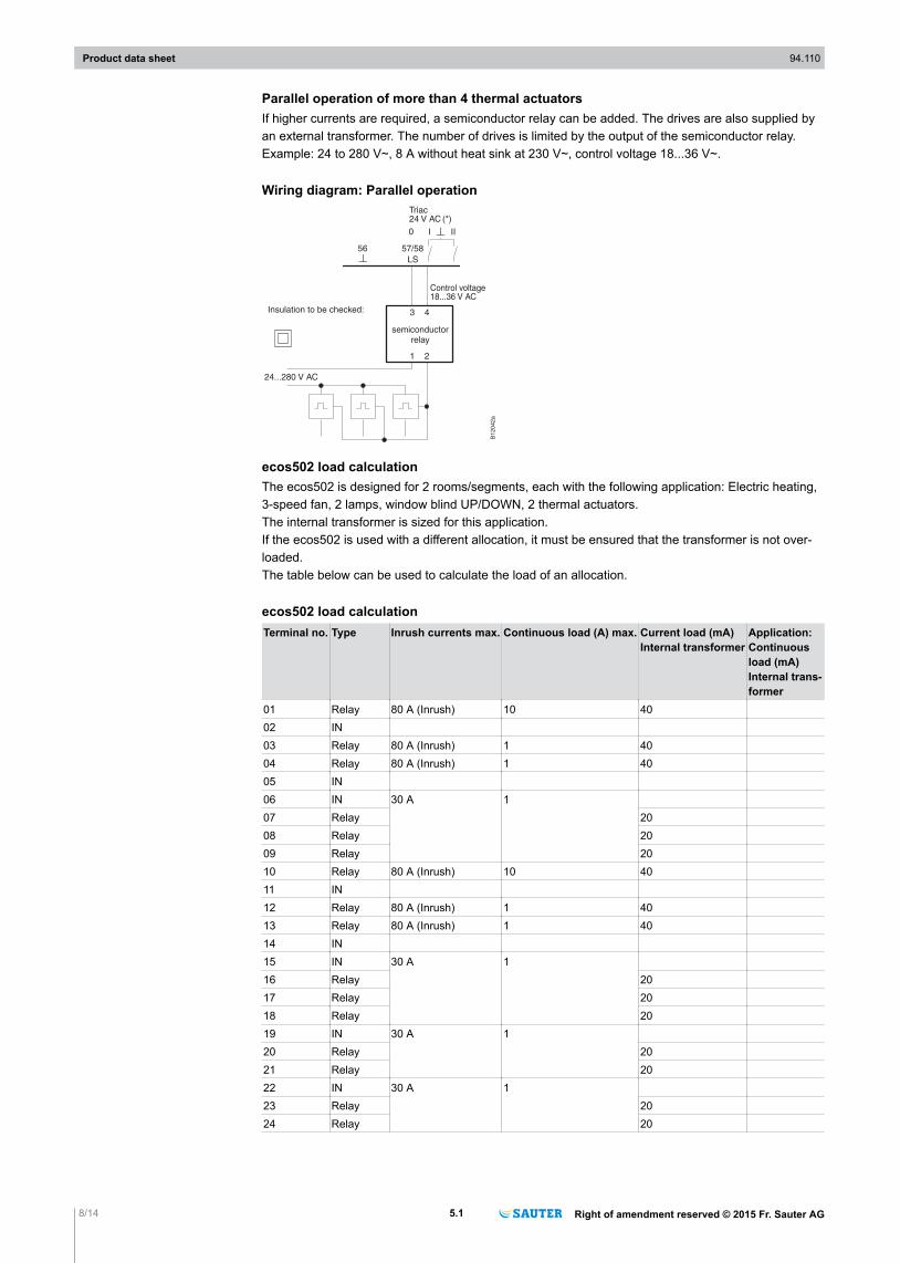
ecos502 load calculationThe ecos502 is designed for 2 rooms/segments, each with the following application: Electric heating,3-speed fan, 2 lamps, window blind UP/DOWN, 2 thermal actuators.The internal transformer is sized for this application.If the ecos502 is used with a different allocation, it must be ensured that the transformer is not over-loaded.The table below can be used to calculate the load of an allocation.
ecos502 load calculationTerminal no. Type Inrush currents max. Continuous load (A) max. Current load (mA)
Internal transformerApplication:Continuousload (mA)Internal trans-former
01 Relay 80 A (Inrush) 10 4002 IN03 Relay 80 A (Inrush) 1 4004 Relay 80 A (Inrush) 1 4005 IN06 IN 30 A 107 Relay 2008 Relay 2009 Relay 2010 Relay 80 A (Inrush) 10 4011 IN12 Relay 80 A (Inrush) 1 4013 Relay 80 A (Inrush) 1 4014 IN15 IN 30 A 116 Relay 2017 Relay 2018 Relay 2019 IN 30 A 120 Relay 2021 Relay 2022 IN 30 A 123 Relay 2024 Relay 20
Product data sheet 94.110
8/14 5.1 Right of amendment reserved © 2015 Fr. Sauter AG

Terminal no. Type Inrush currents max. Continuous load (A) max. Current load (mA)Internal transformer
Application:Continuousload (mA)Internal trans-former
25 IN 30 A 126 IN27 Relay 2028 Relay 20
57 LS_out 12 VA (=0.5 A) in total58 LS_out59 Triac 24 V~ 1255)
60 Triac 24 V~ 12561 Triac 24 V~ 12562 Triac 24 V~ 12563 Triac 24 V~ 12564 Triac 24 V~ 12565 Triac 24 V~ 12566 Triac 24 V~ 125
Sum SumPermanentcurrent, max.1000 mA
Ethernet system busThe ecos stations have 2 Ethernet connections. These have the functionality of a switch. The wiringmust be performed in accordance with the general rules for Ethernet/IP networks.
CommissioningThe work must always be carried out when the system is disconnected from the electrical supply. Pro-tective ESD measures must be taken before any interventions.
Programming and parameterisationThe complete user program (Engine Plan) and the different parameterisations (BACnet objects, im-ages for moduWeb etc.) are created using CASE Suite. Up to 256 BACnet data points incl. hardwareinputs and outputs can be used.Every ecos502 must be configured for communication in an Ethernet network. All settings such as IPaddress, subnet mask, gateway and instance number (DOI) are parameterised via CASE Sun. Auto-matic configuration via a DHCP server is also possible.To identify the room automation station visually in a network, the CASE Sun commissioning tool canput the run/fault LED in flashing mode.The user program can be loaded from any point in the IP network with CASE Suite. Flashing red LEDindicators show that there is an active download. The data is written to the flash memory and is heldeven if there is a power failure. This ensures a high degree of security with regard to data loss.The inputs and outputs can be parameterised by the user program and used freely for control andregulation tasks.
)NoteDetailed information on BACnet functionality can be found in the PICS documentation.
InitialisationAn initialisation of the room automation station can be carried out with CASE Suite before the down-load.
Firmware/updateThe room automation station is delivered with a current version of the firmware. If a newer version ofthe firmware becomes available before installation and commissioning, the ecos502 can be updateddirectly via the network using CASE Sun. Flashing red LED indicators show that there is an activeupdate.Before commissioning of a room automation station, you must check the firmware version and, if nec-essary, carry out an update.
5) e.g. AXT111F202, AXT211F112/F212
Product data sheet 94.110
Right of amendment reserved © 2015 Fr. Sauter AG 5.1 9/14

Internal clockA battery-buffered real time clock is integrated into the ecos502 for the time programmes. The date,time and time zone are set in ecos when loading the user data.The time, date and time zone can be set manually via the BACnet browser, for example.The BACnet services “DM-TS-B” and “DM-UTC-B” are used to synchronise the time and date auto-matically if the correct BACnet time server data is specified (e.g. novaPro Open).The summer/winter setting (daylight saving) is activated in the network properties [CASE Engine] ofthe automation station (AS) by default and includes all the room automation stations integrated intothe same network..
Time programmes, calendarThe BACnet functionality allows up to 32 time programmes (schedule) and up to 8 calendar objects(calendar) to be created in the ecos502.
Battery, data bufferingA pluggable lithium button-cell battery ensures that the RTC for time programmes (schedule/calendar)and data such as counters, e.g. adaptive control algorithms, are retained in the memory (SRAM),even if there is a power failure. The battery voltage is not monitored by the ecos502.
Technical dataType (standard) Lithium button-cell CR2032Nominal voltage 3 VCapacity 210 mAhDimensions 20 mm x 3.2 mmThe user data from CASE Engine and changed user data (e.g. changed by the BACnet client) arestored persistently in the flash memory and do not require battery buffering.However, it is advisable to safeguard user data (CASE Engine) and modified user data by means of abackup (e.g. BACnet DM-BR).
Behaviour in case of mains failureThere are different types of power failure:Micro-interruptions These micro-interruptions generally last a number of microseconds (0...999 µs). These interruptionsare bridged without any shutdowns or other consequences. The system continues to run in normalmode.Normal interruptions These interruptions generally last a number of seconds or minutes. For the ecos502, this means acorrect shutdown and switching back on correctly according to priority when grid voltage returns. Theecos502 performs this correct shutdown and start-up automatically.For BACnet objects, this means:• The “Notification Class Recipient List” remains and the clients automatically receive the event and
alarm information without logging in again.• One's own COV messages remain.• The COV subscriptions on other stations are logged in again automatically.• Connections between room automation stations (AS-AS) are updated again (re-subscription).• When the grid returns, the room automation station will check the consistency of the data and will
automatically restart communication.
Extension optionsDifferent components can be added to the ecos502 via the SLC interface function.
Note on applicationThe use of occupancy detectors and window contacts can improve energy efficiency. The signals canbe connected both to the digital inputs (channel 38-41/terminal 52-55) and to the universal inputs(channel 26-33/terminal 43-51).
Additional informationFitting instructions P100002325Declaration on materials and the environment MD 94.110Dimension drawing M11477
Product data sheet 94.110
10/14 5.1 Right of amendment reserved © 2015 Fr. Sauter AG

Connection diagram A10577A10679A10680
DisposalWhen disposing of the product, observe the currently applicable local laws.More information on materials can be found in the Declaration on materials and the environment forthis product.
Channel and terminal assignment - ecos502 for 1 room/segmentDescription Terminals, room/segment 1 Field devices (application)
Channel Signal Common OccupancyDigital output(relay 0-I)
0 01 021 03 052 043 07 064 085 096 10 117 12 148 139 16 1510 1711 1812 20 1913 2114 23 2215 2416 27 25, 2617 28
RS-485 A 29, 30, 31, 32GND
Analogue output (0...10 V) 34 38 3735 3936 4037 41
Universal input(Ni/Pt1000/U/DI)
26 43 4227 4428 4529 46 4730 4831 4932 5033 51
Digital input (DI) 38 52 5639 5340 5441 55
Voltage output LS (24 V~) 5758
Digital output (Triac 0-I) 18 5919 6020 6121 6222 6323 6424 6525 66
Product data sheet 94.110
Right of amendment reserved © 2015 Fr. Sauter AG 5.1 11/14

Channel and terminal assignment – ecos502 for 2 rooms/segments (1 device with 2functionally identical segments [2 virtual ecos])Description Terminals Field devi-
ces(Applica-tion)
Room/seg-ment
Room/segment 1 Room/segment 2Channel Signal Common Signal Common Occupancy 1 2
Digital output (relay 0-I) 0 01 02 10 111 03 05 12 142 04 133 07 06 16 154 08 175 09 1812 20 19 23 2213 21 24
RS-485 --- 29, 30, 31, 32GND GND
Analogue output (0...10 V) 34 38 37 40 3735 39 41
Universal input(Ni/Pt1000/U/DI)
26 43 4247
48 424727 44 49
28 45 5029 46 51
Digital input (DI) 38 52 56 54 5639 53 55
Voltage output LS (24 V~)Digital output (Triac 0-I)
--- 57, 5818 59 6319 60 6420 61 6521 62 66
Connection diagram
d
Product data sheet 94.110
12/14 5.1 Right of amendment reserved © 2015 Fr. Sauter AG

Application exampleRoom automation with temperature control via fan coil unit and light, blind and window control
M
M
3n 3n
M
M
M
M
2) 3)
4)5)
6)
7)
8)
8)
11)
M
EVGEVG
EVG EVG
3)
4)5)
7)
6)
8)
8)
A) A)
B)B)
10)
9) 9)
12)
13) 13)
External facade
Functional axisFunctional axis
EY-modulo 5 ecos
DALI-Bus
Interface
Corridor area
BACnet/IP over Ethernet
A1
06
35
Pos. Description SAUTER type designation6) Documentation1 Window blind actuator (up/down/shading)2 Window motor (open/close)3 Window contacts4 Actuator for unit valves (constant) AXS111F*** PDS 55.0144 Unit valve VUL/BUL PDS 55.008/55.0095 3-speed fan control6 Dew-point monitor EGH102F001 PDS 34.0427 Actuator for unit valves (thermal) AXT111F*** PDS 55.0147 Unit valve VUL/BUL PDS 55.008/55.0098 Lighting control via DALI ballast9 Motion detector10 LCD operating unit, 4 switching functions EY-RU346F001 PDS 94.04010 Switching unit to operating unit, 6 buttons EY-SU306F001 PDS 94.03511 EY-modulo 5 ecos EY-RC502F001 PDS 94.11012 BACnet/DALI Gateway13 Light sensorA Floor-mounted fan coil unitB Chilled-ceiling element
6) Necessary accessory components are not included in the bill of materials
Product data sheet 94.110
Right of amendment reserved © 2015 Fr. Sauter AG 5.1 13/14

Connection diagram of EY-RC502F511: Application for fan coil unit system, 4-pipe
Connection diagram of EY-RC502F521: Application for chilled-ceiling system
Dimension drawing
Product data sheet 94.110
14/14 5.1 Right of amendment reserved © 2015 Fr. Sauter AG
Fr. Sauter AGIm Surinam 55CH-4016 BaselTel. +41 61 - 695 55 55www.sauter-controls.com
Fr. Sauter AGIm Surinam 55CH-4016 BaselTel. +41 61 - 695 55 55www.sauter-controls.com
Fr. Sauter AGIm Surinam 55CH-4016 BaselTel. +41 61 - 695 55 55www.sauter-controls.com