Embed Size (px)
Citation preview

How The Pixie Transceiver Works
… in 18 minutes or less.

Radio Building Blocks
Amplifier Oscillator Mixer

Types • Audio, RF
Function • Power, Signal (voltage)
Amplifiers
Small signal in Larger signal out
Gain = Ratio of output / input
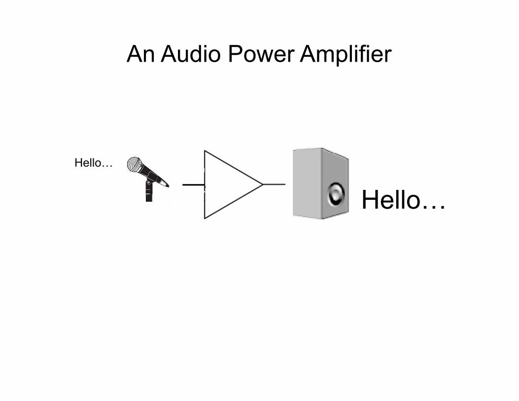
An Audio Power Amplifier
Hello…
Hello…
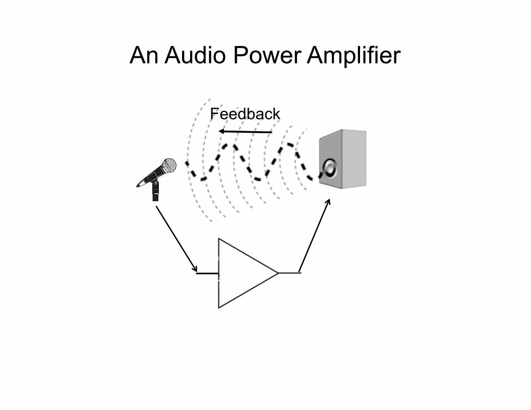
An Audio Power Amplifier
Feedback

Oscillator
How to Make an Oscillator
An amplifier with sufficient gain and positive feedback becomes an oscillator.

Oscillator Frequency Control
Filter
The filter elements can be fixed or adjustable.
A quartz crystal is ideal as a fixed element. • Good frequency stability • Low component count
• Relatively inexpensive

Quartz Crystal Equivalent Circuit

“Rubbering” a Crystal
Trimmer
Padder

Mixers
This Not This
“Frequency Mixer”
“Heterodyne Mixer”
Very non-linear
Audio Mixer
Very linear (Very low distortion)
(Extreme distortion)
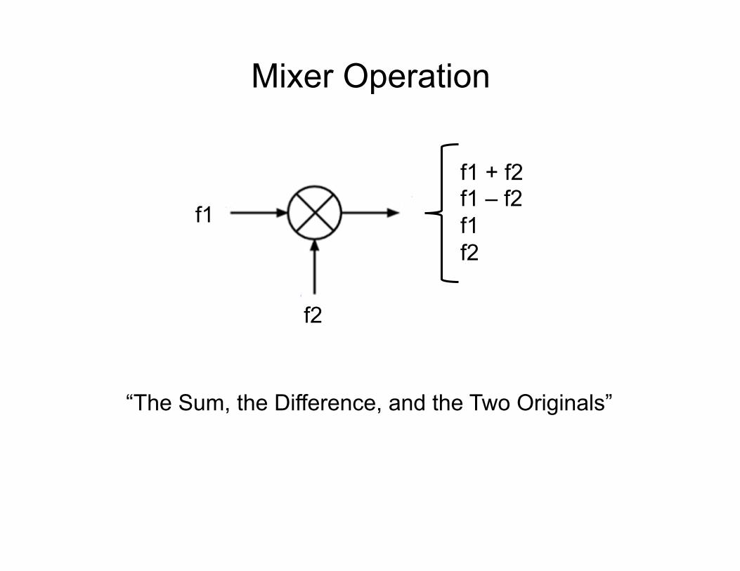
Mixer Operation
f1
f2
f1 + f2 f1 – f2 f1 f2
“The Sum, the Difference, and the Two Originals”

Mixing Example
7,000,000 Hz
14,001,000 Hz 1,000 Hz 7,000,000 Hz 7,001,000 Hz
“The Sum, the Difference, and the Two Originals”
7,001,000 Hz

With those building blocks…
Let’s make radios.

A Simple CW Transmitter
Antenna
Key
Drawbacks: • Component heating can cause drift • Antenna changes can pull frequency • Prone to Chirp

A Better CW Transmitter - MOPA
Antenna
Key
Master Oscillator Power Amplifier

A Simple Radio Receiver
This is known as a Direct Conversion Receiver
Audio

Direct Conversion Receiver Operation
7,000,000 Hz Radio Signal
7,001,000 Hz Oscillator Frequency
1,000 Hz Audio Note
(The difference)

Now… On to the Pixie

The Pixie Transceiver
Original “Pixie 2” c. 1995 NorCal QRP Club Based on “Micro-80” design c. 1992 RV3GM Loosely based on “Foxx” design c. 1982 GM3OXX
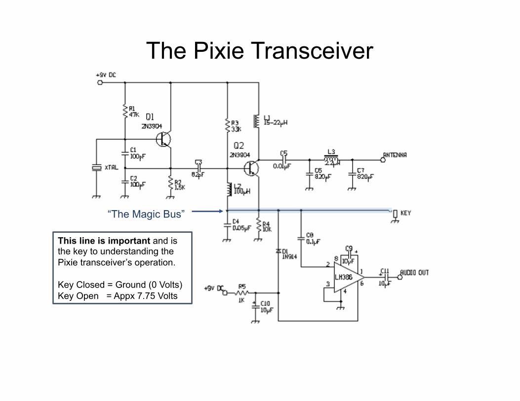
The Pixie Transceiver
This line is important and is the key to understanding the Pixie transceiver’s operation. Key Closed = Ground (0 Volts) Key Open = Appx 7.75 Volts
“The Magic Bus”

The Magic Bus – Key Closed
Key Closed = Ground (0 Volts)
Power Rail for Audio Amplifier
DC supply voltage to the Audio Amplifier is shorted to Ground thru diode D1. This turns off the audio amplifier during xmit.
(Closed)

Pixie Key Closed - Transmitter
Master Oscillator Power Amplifier
Pi-network Output Filter
(Closed) Colpitts Oscillator

Local Oscillator
Mixer
Audio Amplifier
RF LO
Audio
Pixie Key Open - Receiver
(Open)

The Magic Bus – Key Open
Key Open = 7.75 Volts
4.5 Volts
Audio doesn’t flow thru reverse-biased D1
Audio
RF LO
High resistance effectively disables RF amplifier and turns it into a simple mixer
The value of C4 makes it a high reactance at audio frequencies, but a dead short at RF frequencies. This eliminates the f1, f2, and f1+f2 components from the mixer output.

Super Pixie Additions

Adding a Bit of Frequency Mobility
Varying the DC voltage applied to the diode varies the diode’s capacitance. This slightly changes the crystal’s resonant frequency.
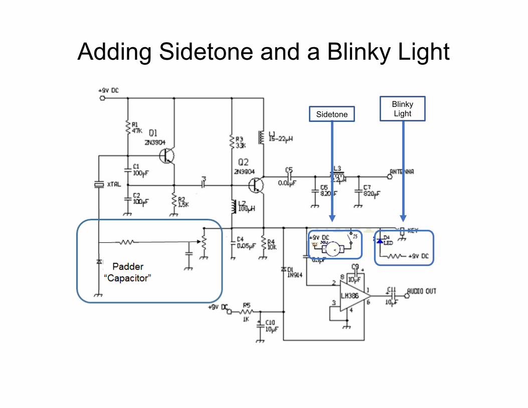
Adding Sidetone and a Blinky Light
Sidetone Blinky Light
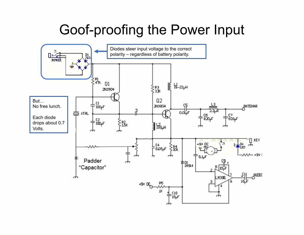
Goof-proofing the Power Input Diodes steer input voltage to the correct polarity – regardless of battery polarity.
But… No free lunch. Each diode drops about 0.7 Volts.
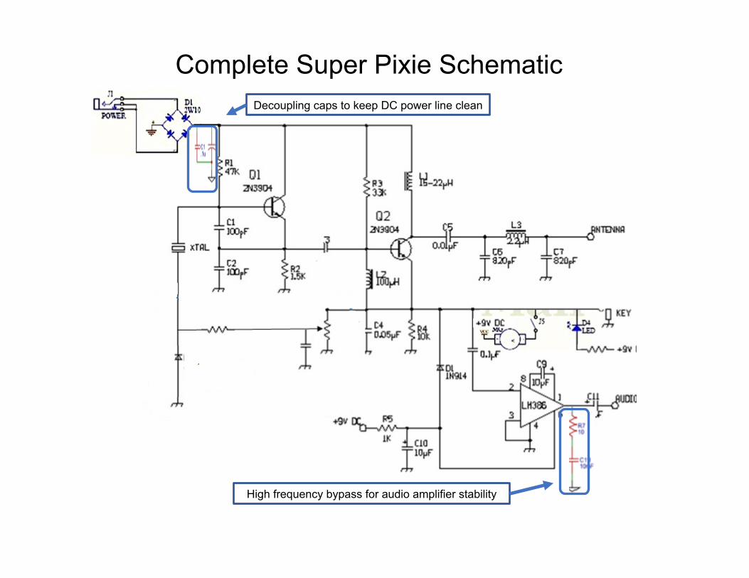
Complete Super Pixie Schematic Decoupling caps to keep DC power line clean
High frequency bypass for audio amplifier stability

Super Pixie Schematic – Chinese Rendition

That’s the Pixie.
Is it an elegant minimalist design… Or a clever hack? Either way, it’s fun to build and a real thrill to make contacts on the air with a rig you built yourself.