Embed Size (px)
Citation preview

How To Build a 3D Computer Graphics Camera
Using Only Your Arms and 4 Feet of String
JJ Ventrella
http://www.ventrella.com October, 2004
Who is This Paper Intended For? If you are intrigued by 3D computer graphics, or if you are a professional Nerd, and you are interested in cognitive science, and the philosophy of Math, you may be interested in this paper. This is a casual (yet thorough) exploration of my personal journey towards inventing a 3D projection routine for a home-grown graphics library, using real-world metaphors as a guide. In this paper I don’t take math (or myself) too seriously – though you will notice that I have thought about it a lot.
1. Introduction I don’t do mathematical equations. When I'm reading a book to learn a computer graphics technique, it’s because I want some suggestions on how to make something, not to see the sheer analytical elegance of the concept behind an algorithm - I can usually arrive at that understanding myself in the

process of making the thing and getting it to work. And having made the journey gives me that extra sense of appreciation. I got into software programming because I found that it was a new and exciting way to build my creative contraptions – without having to endure splinters or getting dirt under my fingernails. Of course, the way I program, I'm always getting VIRTUAL splinters and dirt under my fingernails. I'm referring to the mishaps that come along with playing with materials you are not entirely familiar with. But then that's all a part of the process of invention, and discovery. Many many small failures, and corrections, add up to a deeper understanding of the tools and the problem-space. To be sure, the computer science and math I have picked up over the years is great, and in the long run, invaluable. But before I know why I should care about them, equations are academic, dry, un-motivating. I have been thumbing through computer graphics text books for years, looking at illustrations. Occasionally I read something. And I usually get a mental block when mathematical equations come up. Instead of forming a complete understanding of the technique, I usually end up taking a labyrinthine route, re-inventing the wheel, even though it would otherwise take mere minutes to implement, that is, if I would just follow the instructions. The call glFrustum, r, b, t, n, f(l, r, b, t, n, f) generates R, where:
R is defined as long as , , and . But I'm thankful for the fact that I don't want to understand this - because I love taking the long way there. I love the journey. I Was a Math Flunky Okay, I'll get right to the point: I was a math flunky in both High School and college. I mean really bad. With such dismal math credentials, I got a boost of encouragement when I was accepted into MIT as a graduate student in 1992 (The people at the MIT Media Lab were more interested in a candidate’s accomplishments). In case you didn’t hear that, I’ll say it again: MIT: Massachusetts Institute of Technology, the Graduate Program. How does a math flunky get away with this? Anyway, while there, the teachings of Papert, Minsky, Brooks, and other like minds had reinforced for me the confidence that my intuitive techniques and way of tapping into physical metaphors to solve abstract problems was OK, and not a mental defect. Not only
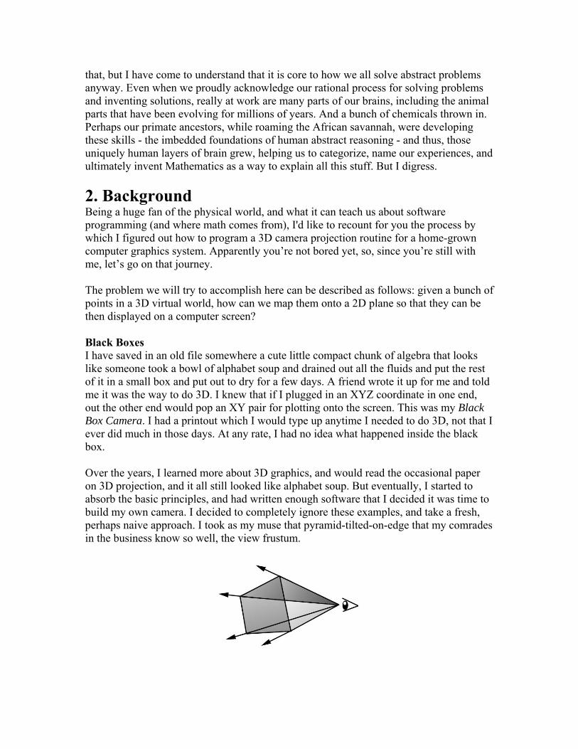
that, but I have come to understand that it is core to how we all solve abstract problems anyway. Even when we proudly acknowledge our rational process for solving problems and inventing solutions, really at work are many parts of our brains, including the animal parts that have been evolving for millions of years. And a bunch of chemicals thrown in. Perhaps our primate ancestors, while roaming the African savannah, were developing these skills - the imbedded foundations of human abstract reasoning - and thus, those uniquely human layers of brain grew, helping us to categorize, name our experiences, and ultimately invent Mathematics as a way to explain all this stuff. But I digress. 2. Background Being a huge fan of the physical world, and what it can teach us about software programming (and where math comes from), I'd like to recount for you the process by which I figured out how to program a 3D camera projection routine for a home-grown computer graphics system. Apparently you’re not bored yet, so, since you’re still with me, let’s go on that journey. The problem we will try to accomplish here can be described as follows: given a bunch of points in a 3D virtual world, how can we map them onto a 2D plane so that they can be then displayed on a computer screen? Black Boxes I have saved in an old file somewhere a cute little compact chunk of algebra that looks like someone took a bowl of alphabet soup and drained out all the fluids and put the rest of it in a small box and put out to dry for a few days. A friend wrote it up for me and told me it was the way to do 3D. I knew that if I plugged in an XYZ coordinate in one end, out the other end would pop an XY pair for plotting onto the screen. This was my Black Box Camera. I had a printout which I would type up anytime I needed to do 3D, not that I ever did much in those days. At any rate, I had no idea what happened inside the black box. Over the years, I learned more about 3D graphics, and would read the occasional paper on 3D projection, and it all still looked like alphabet soup. But eventually, I started to absorb the basic principles, and had written enough software that I decided it was time to build my own camera. I decided to completely ignore these examples, and take a fresh, perhaps naive approach. I took as my muse that pyramid-tilted-on-edge that my comrades in the business know so well, the view frustum.
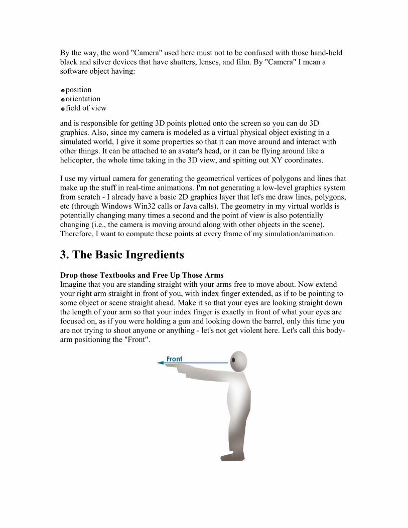
By the way, the word "Camera" used here must not to be confused with those hand-held black and silver devices that have shutters, lenses, and film. By "Camera" I mean a software object having: ☻position ☻orientation ☻field of view and is responsible for getting 3D points plotted onto the screen so you can do 3D graphics. Also, since my camera is modeled as a virtual physical object existing in a simulated world, I give it some properties so that it can move around and interact with other things. It can be attached to an avatar's head, or it can be flying around like a helicopter, the whole time taking in the 3D view, and spitting out XY coordinates. I use my virtual camera for generating the geometrical vertices of polygons and lines that make up the stuff in real-time animations. I'm not generating a low-level graphics system from scratch - I already have a basic 2D graphics layer that let's me draw lines, polygons, etc (through Windows Win32 calls or Java calls). The geometry in my virtual worlds is potentially changing many times a second and the point of view is also potentially changing (i.e., the camera is moving around along with other objects in the scene). Therefore, I want to compute these points at every frame of my simulation/animation. 3. The Basic Ingredients Drop those Textbooks and Free Up Those Arms Imagine that you are standing straight with your arms free to move about. Now extend your right arm straight in front of you, with index finger extended, as if to be pointing to some object or scene straight ahead. Make it so that your eyes are looking straight down the length of your arm so that your index finger is exactly in front of what your eyes are focused on, as if you were holding a gun and looking down the barrel, only this time you are not trying to shoot anyone or anything - let's not get violent here. Let's call this body-arm positioning the "Front".

Now, while still looking straight ahead, extend your right arm to be aimed to your right. You should not be able to see you arm because it is outside the periphery of your vision. Call this "Right".
Now, while still looking ahead, extend your right arm straight up into the air, vertically. Call this "Up".
These three directions, Front, Right, and Up, and the feeling and memory of your arms in these three orthogonal directions, will be important to hold onto. Bake them into your hippocampus (although your remote ancestors probably have already have done this). If you are already experienced in computer graphics, engineering, or 3D design, and have had to deal with coordinate systems, this is a no-brainer. Please don't ask me to get into whether I use the left-handed or the right-handed coordinate system, or whether Y is up or Z is up. I use the "whole-body-standing-straight-up" coordinate system. X,Y, and Z are just three letters floating in the bowl of soup I mentioned earlier.
► Coding Tip #1
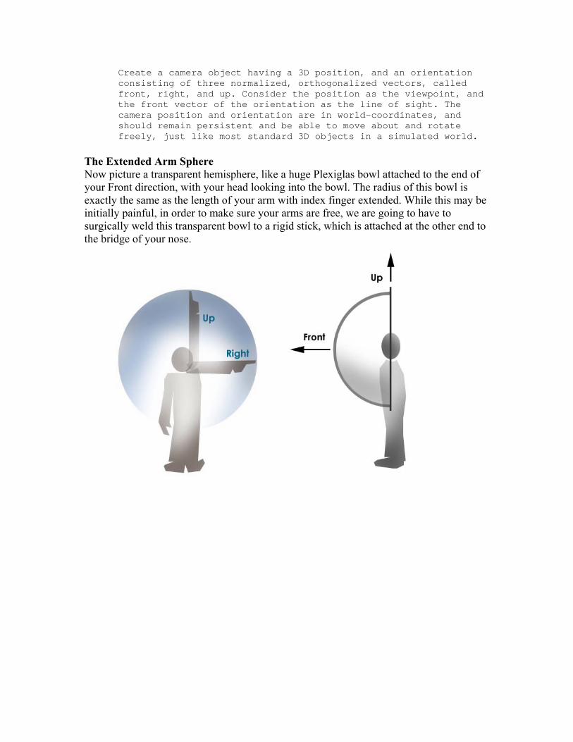
Create a camera object having a 3D position, and an orientation consisting of three normalized, orthogonalized vectors, called front, right, and up. Consider the position as the viewpoint, and the front vector of the orientation as the line of sight. The camera position and orientation are in world-coordinates, and should remain persistent and be able to move about and rotate freely, just like most standard 3D objects in a simulated world.
The Extended Arm Sphere Now picture a transparent hemisphere, like a huge Plexiglas bowl attached to the end of your Front direction, with your head looking into the bowl. The radius of this bowl is exactly the same as the length of your arm with index finger extended. While this may be initially painful, in order to make sure your arms are free, we are going to have to surgically weld this transparent bowl to a rigid stick, which is attached at the other end to the bridge of your nose.
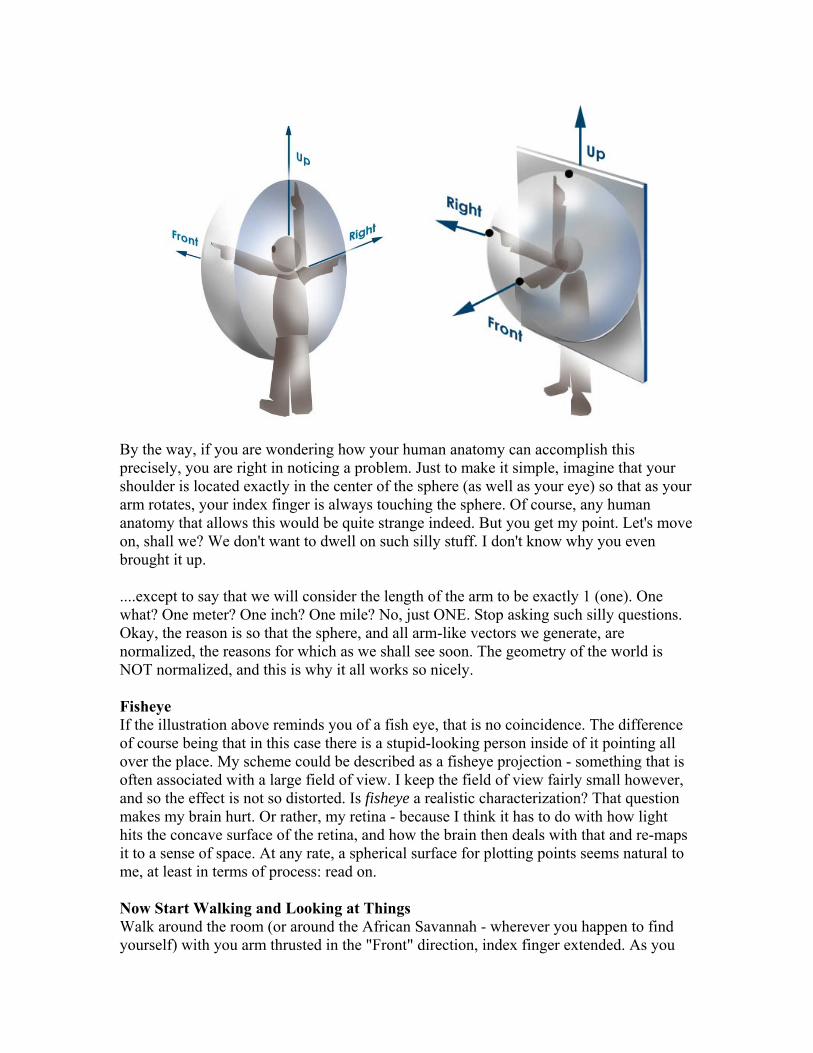
By the way, if you are wondering how your human anatomy can accomplish this precisely, you are right in noticing a problem. Just to make it simple, imagine that your shoulder is located exactly in the center of the sphere (as well as your eye) so that as your arm rotates, your index finger is always touching the sphere. Of course, any human anatomy that allows this would be quite strange indeed. But you get my point. Let's move on, shall we? We don't want to dwell on such silly stuff. I don't know why you even brought it up. ....except to say that we will consider the length of the arm to be exactly 1 (one). One what? One meter? One inch? One mile? No, just ONE. Stop asking such silly questions. Okay, the reason is so that the sphere, and all arm-like vectors we generate, are normalized, the reasons for which as we shall see soon. The geometry of the world is NOT normalized, and this is why it all works so nicely. Fisheye If the illustration above reminds you of a fish eye, that is no coincidence. The difference of course being that in this case there is a stupid-looking person inside of it pointing all over the place. My scheme could be described as a fisheye projection - something that is often associated with a large field of view. I keep the field of view fairly small however, and so the effect is not so distorted. Is fisheye a realistic characterization? That question makes my brain hurt. Or rather, my retina - because I think it has to do with how light hits the concave surface of the retina, and how the brain then deals with that and re-maps it to a sense of space. At any rate, a spherical surface for plotting points seems natural to me, at least in terms of process: read on. Now Start Walking and Looking at Things Walk around the room (or around the African Savannah - wherever you happen to find yourself) with you arm thrusted in the "Front" direction, index finger extended. As you

walk around, turning occasionally, notice that your arm rotates along with you, effectively pointing to things in the environment exactly in front, where your eyes are gazing. You may not want to do this in public, as people would think that you are either an 3D computer graphics engineer, or a nut-case. 4. Pointing At Things If you were gazing at a tree in the distance through your transparent Plexiglas bowl, and off to the right and slightly closer to you, were a small shrub, these two objects would be within view. The tree would be exactly in front and the shrub a little to the right and down a bit.
If you then point to the shrub with your right index finger, then you have essentially defined a new direction, similar to the Front, Right, and Up directions, only this one is not orthogonal to any of them.
► Coding Tip #2 As part of the process for projecting 3D coordinates to the computer screen, create a 3D vector that represents your arm as it points to things within view, like the shrub. Make sure to normalize it - so that it's length is equal to the length of your arm (consider your arm to be of length 1). Call this the "pointing vector".
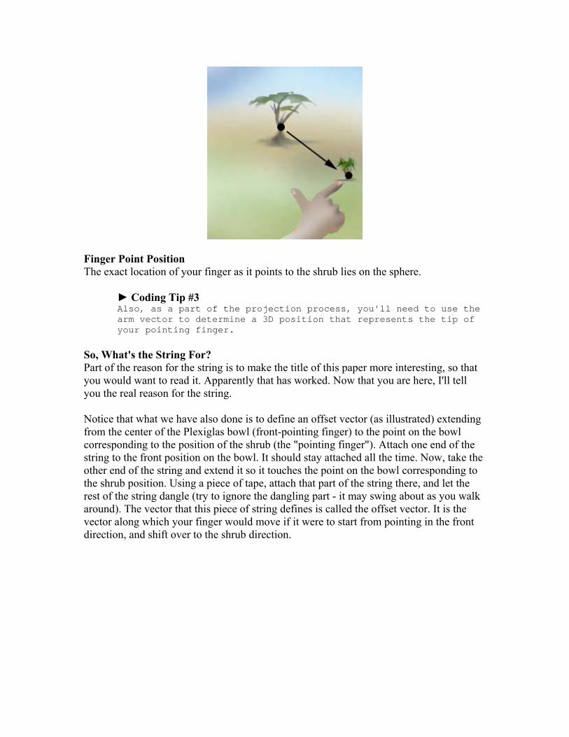
Finger Point Position The exact location of your finger as it points to the shrub lies on the sphere.
► Coding Tip #3 Also, as a part of the projection process, you'll need to use the arm vector to determine a 3D position that represents the tip of your pointing finger.
So, What's the String For? Part of the reason for the string is to make the title of this paper more interesting, so that you would want to read it. Apparently that has worked. Now that you are here, I'll tell you the real reason for the string. Notice that what we have also done is to define an offset vector (as illustrated) extending from the center of the Plexiglas bowl (front-pointing finger) to the point on the bowl corresponding to the position of the shrub (the "pointing finger"). Attach one end of the string to the front position on the bowl. It should stay attached all the time. Now, take the other end of the string and extend it so it touches the point on the bowl corresponding to the shrub position. Using a piece of tape, attach that part of the string there, and let the rest of the string dangle (try to ignore the dangling part - it may swing about as you walk around). The vector that this piece of string defines is called the offset vector. It is the vector along which your finger would move if it were to start from pointing in the front direction, and shift over to the shrub direction.

► Coding Tip #3 As a part of the projection process, you'll need to create the 3D offset vector that represents the piece of string.
Perspective and Foreshortening Come for Free If the shrub were closer to the camera (i.e., lower in the field of view), the extent of the string segment would have to be longer. Likewise, if the shrub were farther off to the right, the extent of the string length would have to be longer. Basically, all the properties of perspective come for free. How Far to the Right or Left, and How Far Up or Down? Now comes a part that is not as straightforward as the previous steps. We need to figure out some things about this piece of string, like, how far to the right does it extend, and how far down does it extend? As you have probably already guessed, this will determine the horizontal and vertical positions to be plotted onto the computer screen.
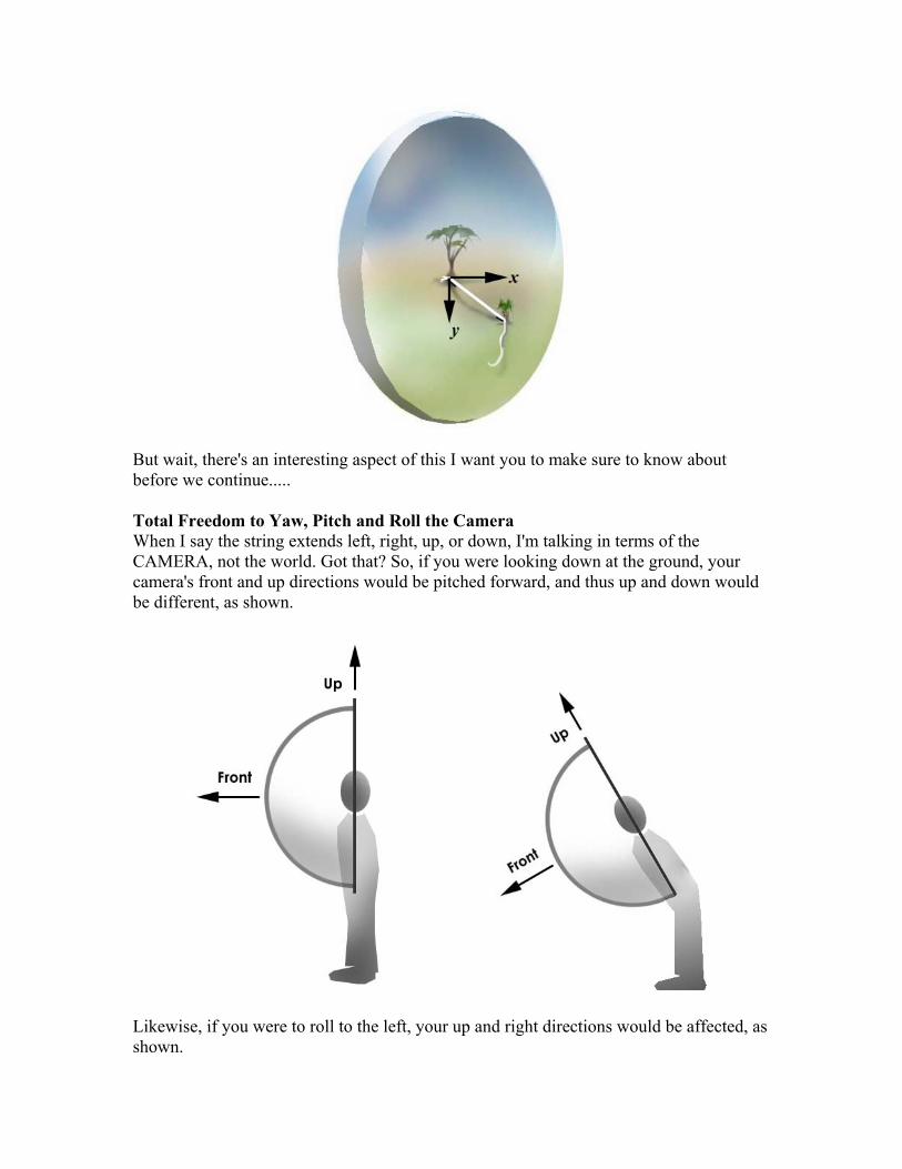
But wait, there's an interesting aspect of this I want you to make sure to know about before we continue..... Total Freedom to Yaw, Pitch and Roll the Camera When I say the string extends left, right, up, or down, I'm talking in terms of the CAMERA, not the world. Got that? So, if you were looking down at the ground, your camera's front and up directions would be pitched forward, and thus up and down would be different, as shown.
Likewise, if you were to roll to the left, your up and right directions would be affected, as shown.
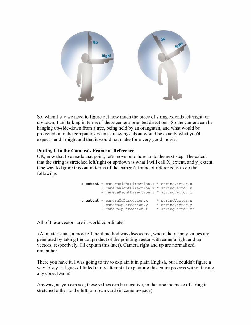
So, when I say we need to figure out how much the piece of string extends left/right, or up/down, I am talking in terms of these camera-oriented directions. So the camera can be hanging up-side-down from a tree, being held by an orangutan, and what would be projected onto the computer screen as it swings about would be exactly what you'd expect - and I might add that it would not make for a very good movie. Putting it in the Camera's Frame of Reference OK, now that I've made that point, let's move onto how to do the next step. The extent that the string is stretched left/right or up/down is what I will call X_extent, and y_extent. One way to figure this out in terms of the camera's frame of reference is to do the following:
x_extent = cameraRightDirection.x * stringVector.x + cameraRightDirection.y * stringVector.y + cameraRightDirection.z * stringVector.z; y_extent = cameraUpDirection.x * stringVector.x + cameraUpDirection.y * stringVector.y + cameraUpDirection.z * stringVector.z;
All of these vectors are in world coordinates. (At a later stage, a more efficient method was discovered, where the x and y values are generated by taking the dot product of the pointing vector with camera right and up vectors, respectively. I'll explain this later). Camera right and up are normalized, remember. There you have it. I was going to try to explain it in plain English, but I couldn't figure a way to say it. I guess I failed in my attempt at explaining this entire process without using any code. Damn! Anyway, as you can see, these values can be negative, in the case the piece of string is stretched either to the left, or downward (in camera-space).
► Coding Tip #4 Using the process just described, compute the x and y extent of the string within the camera frame of reference, to determine an offset from the center of the screen for plotting the 2D point.
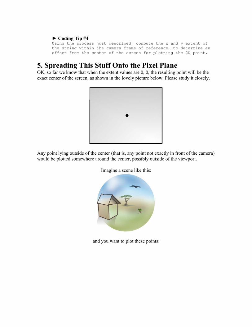
5. Spreading This Stuff Onto the Pixel Plane OK, so far we know that when the extent values are 0, 0, the resulting point will be the exact center of the screen, as shown in the lovely picture below. Please study it closely.
Any point lying outside of the center (that is, any point not exactly in front of the camera) would be plotted somewhere around the center, possibly outside of the viewport.
Imagine a scene like this:
and you want to plot these points:
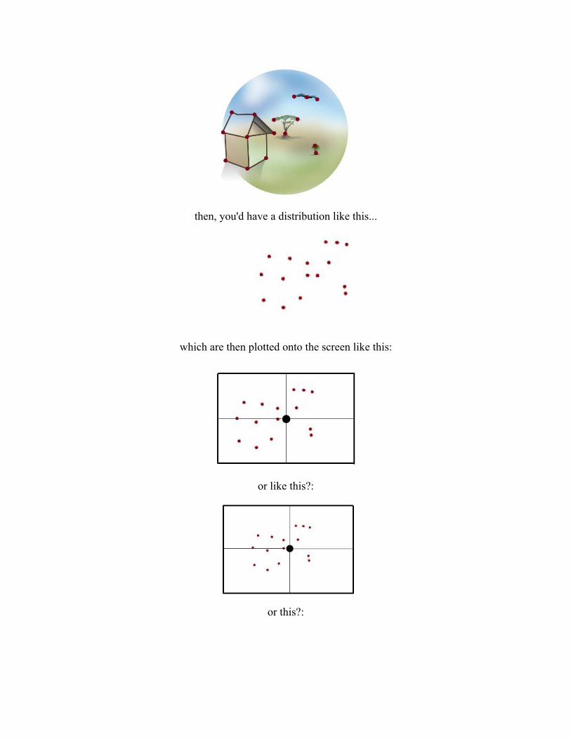
then, you'd have a distribution like this...
which are then plotted onto the screen like this:
or like this?:
or this?:

My point is...how much should these x and y values be scaled? I knew that the x and y extents determined how far away from the center the point needed to be plotted, but exactly what is the scaling factor? Before knowing the answer, I just picked some arbitrary scale-factor, and tweaked it a few times to get something on the screen, to make sure that what was being plotted was reasonable, knowing that the only difference would be that the size of things would be off. Indeed, my predictions were correct: things were plotting correctly, yet without any control over scale. Knowing the Size of the Screen Pixel dimensions One thing seemed obvious: the size of the computer screen, in pixels, would have to be known. More specifically, the camera needed to know the dimensions of the viewport window, as one would query using WindowsTM (copyright Microsoft Corporation, all right reserved, and shit like that).
► Coding Tip #5 Along with position and orientation, add to the camera's attributes the pixel width and height of the screen, so that it can know the range within which to plot the points. You could argue that it is not really the camera's job to know this, and that it could just produce normalized x,y coordinates, which the rendering system then maps to the screen. I just happen to have done it this way.
Once the screen dimensions were considered, I knew there still had to be something that would determine the amount that these points needed to be scaled about the center point. Aha - the answer is Field of View!
► Coding Tip #6 One more thing to add to the camera's attributes: field of view.
Getting the Correct Field of View Camera field of view ranges between 60 and 80 in the 3D graphics systems I've seen and worked on. If the camera is set to have a narrow field of view (like 30 degrees), then a smaller amount of stuff would be visible within the window and everything would be scaled larger. Likewise, if field of view is large, like 100 degrees, then a whole lot of stuff is visible, the scaling is smaller, and there is strong perspective distortion.

So, as a first step, I just created a scaling constant called "fieldOfViewLikeFactor", and started playing around with it, until I figured it out, and got it to behave consistently with expectation, using some, uh, Math. So, for instance, when field of view is set to 180, EVERYTHING in front of the camera ends up on the screen, and things off in the periphery look very distorted. When field of view is set to something tiny, like 10, then there is very little perspective distortion, and it's like looking through binoculars. Done. The scaling issue was solved. At least I think it was. Clipping Everything Behind the Camera. As I mentioned earlier, I don't have to clip lines that go off the edge of the window, but I do have to clip lines that extend to the region behind the camera. So I don't plot those points. The check for this is to take the dot product of the pointing vector with the camera's front vector. If it is negative (behind) don't plot. The tricky part is if I want to draw a line with one endpoint in front and one behind. The proper thing to do would be to clip the line, but I just don't draw the line at all. Most lines either fall entirely in front or behind the camera. Those that cross over are usually out of the field of view. I don’t plot those at all. The clipping scenario isn't perfect, but for my purposes, it is fine, at least that has been the case so far. 5. Animation/Simulation As long as the camera projects the 3D coordinates to the screen every step of the simulation/animation, and hands the resulting 2D coordinates to the rendering system to refresh the graphics, anything can change. For instance, the camera can move through space, rotate, even change its field of view, and the world will get mapped to the screen appropriately. 6. An Improved Algorithm I discovered a more efficient way to accomplish this projection algorithm, although it is not as easy to explain using real-world metaphors. However I wanted to explain my first version so you could get the general idea, and also, that is the order in which I arrived at the final solution. The new version avoids the normalization of the pointing vector (an expensive operation considering how many times it is used in the animation/rendering loop), as well as many other operations. Instead, I just take the dot product of the non-normalized pointing vector with the camera's right and up vectors to attain the x_extent and y_extent values, respectively. Then I use a scale factor proportional to the inverse of the distance to the 3D point, squared, like so: double inverseDistanceSquared = 1.0 / magnitudeSquared( pointingVector ); double scale = ( 180.0 - field_of_view ) * inverseDistanceSquared;

(oops, I'm showing code again! - I couldn't help myself). Then it is mapped to the pixel dimensions of the window. The exact reasons why this works is not clear yet, so I cannot explain it completely. Yet. I am a little nervous that there is a flaw in it. Though it hasn't come up visually. Yet. Good enough for jazz.
► Coding Tip #7 Use this version.
6. The Moral of the Story You may have already come to the following conclusion: If you want to get 3D coordinates projected onto a 2D plane, such as your computer screen, you should get one of those fancy new graphics cards installed into your computer and use some standard 3D software library such as OpenGL, Direct3D, or Java3D, and get to work. You probably don't want to waste your time doing all that stuff I did. Besides, these new graphics cards are really, really FAST. On the Other Hand... If you enjoy going through the process of figuring out algorithms like I do, go for it. You may come up with a better way than I have. I believe the excitement of figuring this out may provide a hint of what the inventor(s) of the camera obscura must have felt during the renaissance, or when the Jim Blinn's of the world first did it on a computer. For me, the interesting part is the cognitive development behind discovery. While I may not have invented a better camera projection scheme, the journey along the way has primed my mind for other discoveries and inventions that might actually be novel and useful to somebody some day.
---------- An Example To see something that uses the camera just described, download the following Windows executable program: http://www.ventrella.com/Simulation/Bird/bird.html