Embed Size (px)
DESCRIPTION
termo par
Citation preview

16/11/2015 How to Build a Thermocouple Amplifier | Hackaday
http://hackaday.com/2015/04/06/how-to-build-a-thermocouple-amplifier/ 1/11
37 Comments
April 6, 2015
HOW TO BUILD ATHERMOCOUPLEAMPLIFIERby: Bil Herd
A Thermocouple is a terrific way to measure temperature. The effects of temperaturechange on dissimilar metals produces a measurable voltage. But to make thatmeasurement you need an amplifier circuit designed for the thermocouple being used.
While researching “Zero Drift Amplifiers” as a follow-up to my video on InstrumentationAmplifiers I noticed the little schematic the front page of the LTC1049 datasheet whichis shown here. I thought it was an ideal example of an analog application where some
SEARCH
Search … SEARCH
NEVER MISS A HACK
IF YOU MISSED IT
HACKADAYHOME BLOG HACKADAY.IO STORE HACKADAY PRIZE SUBMIT ABOUT November 16, 2015

16/11/2015 How to Build a Thermocouple Amplifier | Hackaday
http://hackaday.com/2015/04/06/how-to-build-a-thermocouple-amplifier/ 2/11
Linear Technology LTC 1049 Low Power Zero-DriftOperational Amplifier
with Internal Capacitors
gain and some “gainhelper” were needed toaccomplish our usefullittle application ofamplifying athermocouple probe.
In the video I don’t reallytalk much about thethermocouplesthemselves other than thetype I see most of thetime which is type K. Ifyou’re not already familiarwith the construction ofthese probes you can findan informative write-up onthermocouples and thedifferent types on theWikipedia page and youmight also want to check
out the Analog Devices app note if you would like to know more. What I will cover is areliable and precise way to read from these probes, seen in the video below and theremainder of the post after the break.
How to Measure a Thermocouple Probe using an Amplifier ...
Different thermocouples sensors have a different temperature coefficients meaningthat they will generate different amounts of voltage for the same change intemperature, usually specified in volts per degree of Celsius (v/C). Knowing thetemperature coefficient of a sensor is only half the equation, we also need to nail downthe zero point, meaning that we establish a calibrated reference point. Applying aknown temperature such as immersing the sensor in ice water would be a simple ifinconvenient way to establish a known reference temperature. Basically we could zeroout and measure the change in volts per degree C from there. Below is a graphshowing
Alternatively we could use a Cold Junction Compensator (CJC) such as the LT1025, achip made to not only replicate the different temperature coefficients of the variousthermocouples, but also give us a pretty reasonable calibration.
Behind the scenes the CJC acts as another thermocouple or thermometer and
EYEDRIVEOMATIC WINSTHE 2015 HACKADAYPRIZE
18 Comments
SEEKING DISTINCTHARDWARE PASSION
7 Comments
CODE CRAFT –EMBEDDING C++:TIMING VIRTUALFUNCTIONS
35 Comments
YOUR FIRST GNU RADIORECEIVER WITHSDRPLAY
11 Comments
GETTING STARTEDWITH GNU RADIO
21 Comments
HACKADAY LINKS:NOVEMBER 15, 2015
11 Comments
HACKLET 84 – ALARMCLOCKS
9 Comments
RETROTECHTACULAR: AMECHANICAL UART
32 Comments
More from this category
CATEGORIES
Select Category
OUR COLUMNS
16/11/2015 How to Build a Thermocouple Amplifier | Hackaday
http://hackaday.com/2015/04/06/how-to-build-a-thermocouple-amplifier/ 3/11
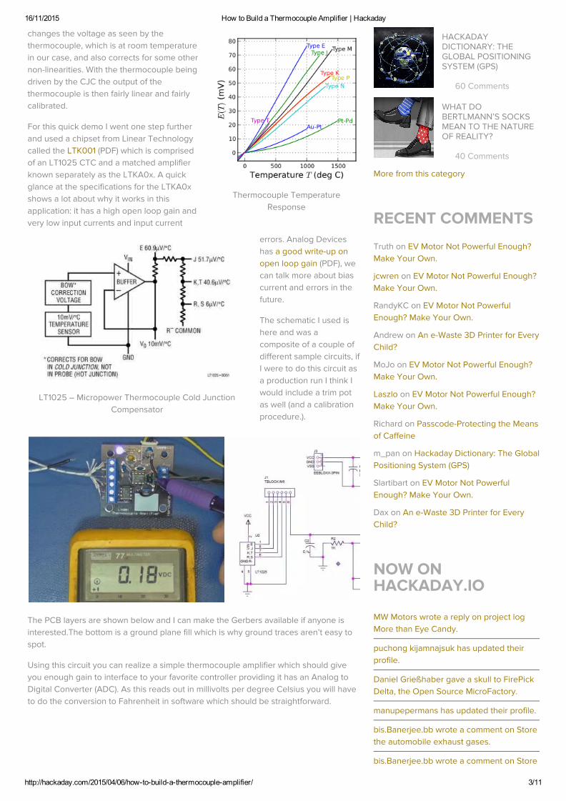
Thermocouple TemperatureResponse
LT1025 – Micropower Thermocouple Cold JunctionCompensator
changes the voltage as seen by thethermocouple, which is at room temperaturein our case, and also corrects for some othernon-linearities. With the thermocouple beingdriven by the CJC the output of thethermocouple is then fairly linear and fairlycalibrated.
For this quick demo I went one step furtherand used a chipset from Linear Technologycalled the LTK001 (PDF) which is comprisedof an LT1025 CTC and a matched amplifierknown separately as the LTKA0x. A quickglance at the specifications for the LTKA0xshows a lot about why it works in thisapplication: it has a high open loop gain andvery low input currents and input current
errors. Analog Deviceshas a good write-up onopen loop gain (PDF), wecan talk more about biascurrent and errors in thefuture.
The schematic I used ishere and was acomposite of a couple ofdifferent sample circuits, ifI were to do this circuit asa production run I think Iwould include a trim potas well (and a calibrationprocedure.).
The PCB layers are shown below and I can make the Gerbers available if anyone isinterested.The bottom is a ground plane fill which is why ground traces aren’t easy tospot.
Using this circuit you can realize a simple thermocouple amplifier which should giveyou enough gain to interface to your favorite controller providing it has an Analog toDigital Converter (ADC). As this reads out in millivolts per degree Celsius you will haveto do the conversion to Fahrenheit in software which should be straightforward.
HACKADAYDICTIONARY: THEGLOBAL POSITIONINGSYSTEM (GPS)
60 Comments
WHAT DOBERTLMANN’S SOCKSMEAN TO THE NATUREOF REALITY?
40 Comments
More from this category
RECENT COMMENTS
Truth on EV Motor Not Powerful Enough?Make Your Own.
jcwren on EV Motor Not Powerful Enough?Make Your Own.
RandyKC on EV Motor Not PowerfulEnough? Make Your Own.
Andrew on An e-Waste 3D Printer for EveryChild?
MoJo on EV Motor Not Powerful Enough?Make Your Own.
Laszlo on EV Motor Not Powerful Enough?Make Your Own.
Richard on Passcode-Protecting the Meansof Caffeine
m_pan on Hackaday Dictionary: The GlobalPositioning System (GPS)
Slartibart on EV Motor Not PowerfulEnough? Make Your Own.
Dax on An e-Waste 3D Printer for EveryChild?
NOW ONHACKADAY.IO
MW Motors wrote a reply on project logMore than Eye Candy.
puchong kijamnajsuk has updated theirprofile.
Daniel Grießhaber gave a skull to FirePickDelta, the Open Source MicroFactory.
manupepermans has updated their profile.
bis.Banerjee.bb wrote a comment on Storethe automobile exhaust gases.
bis.Banerjee.bb wrote a comment on Store

16/11/2015 How to Build a Thermocouple Amplifier | Hackaday
http://hackaday.com/2015/04/06/how-to-build-a-thermocouple-amplifier/ 4/11
← Automated Die Testing 3D Printed Pogo Pin Programmer →
Report comment
Report comment
Posted in Featured, how-to, sliderTagged amplifier, bil herd, k-type thermocouple, op-amp, thermocouple
37 THOUGHTS ON “HOW TO BUILD ATHERMOCOUPLE AMPLIFIER”
Thinkerer says:April 6, 2015 at 7:19 am
Once upon a time thermocouples required special connectors since usingordinary screw terminals would make an additional pair of dissimilar-metaljunctions. Can you compensate that out of these circuits?
Reply
SOI Sentinel says:April 6, 2015 at 7:26 am
I deal with thermocouples industrially, and generally, the amplifierconnection is to normal screw terminals these days. It’s a single point andthey are compensated for, I believe. Now, if you have other junctions alongthe way, then yes, you must use the correct matched set of terminals/plugsto get an accurate reading.
Reply
Bil Herd says:
the automobile exhaust gases.
pauljurczak has updated their profile.
Csernath Geza has updated their profile.
Frenky wrote a comment on instructions forHardware serial port monitor with WiFi.
Ramon Schepers has added laurens.weynas a contributor to Pix-Watch - Teensy 3.2based smartwatch.
16/11/2015 How to Build a Thermocouple Amplifier | Hackaday
http://hackaday.com/2015/04/06/how-to-build-a-thermocouple-amplifier/ 5/11
Report comment
Report comment
Report comment
Report comment
Report comment
April 6, 2015 at 7:56 am
We used to account for things like the kovar leads on TO-5 caseshaving a small additive temperature coefficient depending onwhether it was inside a feedback loop or not, etc. etc.
These days with software usually involved with a measurement, agood calibration procedure can usually take out a lot issues thatcreep in, with the results being better the closer to ideal the originalsignal is.
Also the Cold Junction Compensator uses an approximation for“bow” correction and appears to spread the approximation out overthe various outputs, another source of error at some level.
Reply
Marvin says:April 6, 2015 at 8:25 am
If all your other dissimilar junctions are at the same temperature theSeebeck EMF is equivalent to a single junction of the first and last metals.
Reply
HansPeterHaastrup says:April 6, 2015 at 11:23 pm
If you want to measure in the 0.01’s of degrees, then no – the only optionis to have a well defined hot and cold junction. I’m working in a companythat does measure in that range using thermocouples and yes, there isquite some material controlling being done on the physical side of things
Reply
Don says:April 7, 2015 at 3:23 am
Dealing with industrial signal converters, there is usually a temperaturereference bonded to a leg of the terminal block to provide an accurateCJC.
Reply
netbeard says:April 6, 2015 at 7:50 am
Unless you’re measuring insanely high temperatures, there’s no good reason notto use a pt100 or pt1000 RTD instead of a thermocouple. They’re morereproducible, no drift, and no need for cold junction compensation.
Reply
DainBramage says:April 6, 2015 at 8:40 am
Yes, there is. You can make any amount of thermocouples cheaply,quickly, and easily. All you need is the thermocouple wire itself and a way
16/11/2015 How to Build a Thermocouple Amplifier | Hackaday
http://hackaday.com/2015/04/06/how-to-build-a-thermocouple-amplifier/ 6/11
Report comment
Report comment
Report comment
Report comment
Report comment
Report comment
to weld the tip. RTDs, not so much. From a maintenance perspective, itmakes a lot more sense to keep a spool of thermocouple wire on hand,than needing a drawer full of spare RTDs. Also, when a thermocouplebreaks, you can replace it in seconds with a pair of wire cutters and apropane torch.
Reply
chango says:April 6, 2015 at 8:48 am
Or weld it with a big cap. Non precious metal thermocouple wire (T)are cheap and come spooled and jacketed in zip cord like insulation.
Reply
Matt says:April 6, 2015 at 1:51 pm
Or a rewound savaged transformer from a microwave oven…I’m currently using these when I need to weld small stuff (ormelt something just for the sake of it)
Reply
tekkieneet says:April 7, 2015 at 1:45 am
I used DIY carbon arc welder – alligator clip with mechanicalpencil lead and a small adjustable bench supply (less than 10Vand an amp or so). Worked pretty to weld the twisted end ofthe wires into a nice small round junction.
I tried using the plasma arc from my solid state Telsa coiladjusted all the way down to 10-ish watts, but it was too hotand harder to control.
Reply
christoph says:April 8, 2015 at 6:22 am
How exactly is the big-cap-welding done? I have some Type Kwire left and I’d like to give it a try.
Reply
Matt says:April 6, 2015 at 8:31 am
I tend to use the good old OP07 and any cheap temperature sensor for coldjunction compensation. Data processing is done in software. Works really well –with three-point calibration (ice water, boiling water, melting solder) the accuracyis 2-5K with respect to +/- 0.5K calibrated temp sensor.
Reply

16/11/2015 How to Build a Thermocouple Amplifier | Hackaday
http://hackaday.com/2015/04/06/how-to-build-a-thermocouple-amplifier/ 7/11
Report comment
Report comment
Report comment
Report comment
Report comment
chango says:April 6, 2015 at 8:44 am
This is the way to go, especially where you’re measuring hightemperatures. An OP07 and TMP35 each feeding into separate ADCs on amicro is usually good enough. Way cheaper than those fixed functionthermocouple amp ICs.
Reply
Bil Herd says:April 6, 2015 at 9:05 am
We used to use the OP01 and OP05 which suffered from somepopcorn noise back in the 70’s, and then the OP07 when it cameout, all from from PMI. They used to make some great stuff, looks likethey were bought by Analog Devices. We used to add a matchedtransistor pair to the front end of an OP07 as our instr amp.
Reply
Frank Buss says:April 6, 2015 at 9:15 am
Another way to use a thermocouple is the MAX31855. Just connect thethermocouple, no other parts needed, digital output. I’ve tried it, works even withan external multiplexer for more than one thermocouple, and on a breadboard:https://groups.google.com/forum/#!msg/de.sci.electronics/YEWNNwx-bXI/NT-cdnWah44J
Reply
Bil Herd says:April 6, 2015 at 9:17 am
Cool Frank.
Reply
joo says:April 7, 2015 at 3:38 am
One pitfall with the MAX31855 you can have, is to rely on the internal fixedamplification. With the J-type version the sensitivity is set to 57.953 µV/°Cwhich is fine if you measure 1000°C, at say 200°C according to a J-typedatasheet you would need 53.895 µV/°C, which results in a whopping 15Kerror.
Reply
Artenz says:April 6, 2015 at 10:56 am
I usually grab an AD7792. It comes with pre-amp, 50/60 Hz filtering, currentsource to detect broken sensor, and extra ADC channels for measuring coldjunction with NTC. Only needs NTC, resistor, and a few caps as externalcomponents.

16/11/2015 How to Build a Thermocouple Amplifier | Hackaday
http://hackaday.com/2015/04/06/how-to-build-a-thermocouple-amplifier/ 8/11
Report comment
Report comment
Report comment
Report comment
Report comment
Report comment
Report comment
Reply
Bil Herd says:April 6, 2015 at 11:12 am
Cool. I like being able to mux in a gain and zero reference and null out insoftware providing the mux is mostly neutral.
Reply
chris says:April 6, 2015 at 11:10 am
There is a widely used thermocouple amplifier from analog devices, the ad595:http://www.analog.com/en/products/amplifiers/specialty-amplifiers/thermocouple-interface-amplifiers/ad595.html
Reply
Bil Herd says:April 6, 2015 at 11:12 am
Cool. My last vid used AD so I switched it up to Linear Tech.
Reply
mr.jb.swe says:April 6, 2015 at 11:10 am
I think an Attiny861 with differential gain could be used as a “simple stupid”alternative
Reply
Bil Herd says:April 6, 2015 at 11:21 am
All depends on what you want to get out of it which is the cool part ofdesigning. There is often a near-infinite number of ways to do the samething.
Reply
Ken says:April 6, 2015 at 1:40 pm
This is kinda an old school analog approach?Today, you’d use a thermocouple to digital converter like a Maxim MAX31855.Okay that part sucks for RF susceptability and reading below freezingtemperatures.But calibrating and drift of thermocouple amps is a hassle.
Reply
Bil Herd says:April 6, 2015 at 4:36 pm
16/11/2015 How to Build a Thermocouple Amplifier | Hackaday
http://hackaday.com/2015/04/06/how-to-build-a-thermocouple-amplifier/ 9/11
Report comment
Report comment
Report comment
Report comment
Report comment
Report comment
This circuit is mostly pre-calibrated, the amp is a zero-drift type whichtypically do their own drift correction which is what led to showing it.
Reply
Ren says:April 6, 2015 at 3:16 pm
Okay, my first impression on reading the title of this blog was “amplifying soundusing thermocouples”…The World Book Encyclopedia I had as a child had a “candle powered radio”build instruction which used a multitude ofdissimilar metal junctions to power a small amplifier for a crystal diode AMreceiver.
Reply
Bil Herd says:April 6, 2015 at 4:37 pm
There are thermocouples that directly power a valve just from the voltagethey produce which is kinda cool.
Reply
tmk says:April 6, 2015 at 11:22 pm
I added a safety valve on my vintage stove that just does that. Athermocouple is heated by the pilot light, which provides enoughjuice to keep a valve open.
Reply
Antti says:April 10, 2015 at 5:17 am
You can make this without electricity by using closed tubewhich flame heats. As pressure grows inside tube it keepsvalve open.
Reply
Marvin says:April 7, 2015 at 5:02 pm
It’s possible to evaporate thermocouples onto split mica or blown glasswith so little thermal lag that they are microphonic – responding to thechange in temperature caused by adiabatic compression of air of thesound waves.
Ok, it’s mostly off topic but someone mentioned sound and I may not getanother chance to drop that into a conversation this lifetime. :P
Reply
Bil Herd says:April 7, 2015 at 5:38 pm

16/11/2015 How to Build a Thermocouple Amplifier | Hackaday
http://hackaday.com/2015/04/06/how-to-build-a-thermocouple-amplifier/ 10/11
Report comment
Report comment
Report comment
Report comment
Report comment
I figured there was a path between motion and voltage in there butassumed that it would be limited to low frequency. It is hard to workthe word adiabatic into a casual conversation. :)
My question would then be would there be desirable qualities of asound (pressure) made this way compared to other methods?
Reply
Eric says:April 7, 2015 at 1:36 pm
Bil,
Would it be possible to get the gerbers (or Eagle) files you offered?
Thanks!
Reply
Bil Herd says:April 7, 2015 at 5:45 pm
Hi Eric, I am working now on getting that up for you, I will follow-up whendone.
Reply
Bil Herd says:April 7, 2015 at 7:18 pm
A zip containing the gerber files is athttp://www.herdware.com/shop/analog/thermocouple-amplifier/ closer tothe bottom. It is zipped in a way to be compatible with OSKPark format Ibelieve. You can email me at [email protected] if you have anyquestions.
Reply
Eric says:April 8, 2015 at 9:08 am
Hi Bill,
Thanks! I’ll just buy one since you have them for sale – it saves mefrom making yet another Mouser order. Thanks for making themavailable.
Eric
Reply
Theo says:August 2, 2015 at 1:29 am
I like LT’s explanation of why you need an IC for cold junction compensation.
In the LT1025 datasheet, they are talking about the cold junction traditionally
16/11/2015 How to Build a Thermocouple Amplifier | Hackaday
http://hackaday.com/2015/04/06/how-to-build-a-thermocouple-amplifier/ 11/11
Report comment
being held in a slurry of ice water and say “To date, IC manufacturers efforts tomake microminiature thermos bottles have not been totally successful.Therefore, an electronically simulated cold-junction is required for mostapplications.”
I love it when someone sneaks a joke into a datasheet.
Reply
Leave a Reply
Enter your comment here...
HOMEBLOGHACKADAY.IOSTOREHACKADAY PRIZEVIDEOSUBMIT A TIPABOUTCONTACT US
NEVER MISS A HACK
SUBSCRIBE TO NEWSLETTER
Enter Email Address SUBSCRIBE
Copyright © 2015 | Hackaday, Hack A Day, and the Skull and Wrenches Logo are Trademarks of Hackaday.com Powered by WordPress.com VIP