Embed Size (px)
Citation preview

Rev. 1.1
How to connect Omron NX-CSG320 + NX-SL5500 With
Omron GI-SMDxxxx CIP Safety IO block

Rev. 1.1
Table of Contents 1. Application Devices and Device Configuration ..................................................................................... 1
1.1. Applicable Devices ........................................................................................................................ 1
1.2. Device Configuration ..................................................................................................................... 2
2. EtherNet/IP Safety Connection Procedure ........................................................................................... 3
2.1. Safety Controller Setup ................................................................................................................. 3
2.1.1. Hardware configuration and IP address Settings .................................................................. 3
2.1.2. Starting Sysmac Studio and Going Online ............................................................................. 4
2.1.3. Creating a Safety Controller Unit Configuration ................................................................... 5
2.2. Network Setting with Sysmac Studio ............................................................................................ 6
2.2.1. Setting the Connections ........................................................................................................ 6
2.3. Transferring Program with Sysmac Studio .................................................................................. 11
2.3.1. Setting Global Variables ...................................................................................................... 11
2.3.2. Transferring the Safety Application Data ............................................................................ 12
2.3.3. Transferring the Safety Program ......................................................................................... 13
3. Acknowledgement .............................................................................................................................. 15

Rev. 1.0
1
1. Application Devices and Device Configuration
1.1. Applicable Devices The applicable devices are as follows:
Manufacturer Name Model OMRON Ethernet switch W4S1-0xx OMRON NX-series Safety CPU unit NX-SL5xxx OMRON NX-series Communication Control unit NX-CSGxxxx OMRON Omron Safety I/O block GI-SMD1624

Rev. 1.0
2
1.2. Device Configuration
Manufacturer Name Model Version
OMRON Ethernet switch W4S1-05B OMRON NX-series Safety CPU unit NX-SL5500 Ver. 1.3 OMRON NX-series Communication Control
unit NX-CSG3200 Ver. 1.01
OMRON Sysmac Studio SYSMAC-SE2xxx Ver.1.25.1 OMRON Compress CIP device file CIP_Safety_XXXXX.zip
* XXXXX is a unique name for each target device to be added
OMRON Safety I/O block GI-SMD1624 1.0 - Personal computer (OS: Win 10) - - LAN cable (STP (shielded, twisted-
pair) cable of Ethernet category 5 or higher)
-
GI-SMD1624

Rev. 1.0
3
2. EtherNet/IP Safety Connection Procedure This section describes the procedures for connecting the Omron safety I/O block and the safety controller via EtherNet/IP safety.
2.1. Safety Controller Setup
Set up the Safety Controller. The Sysmac Studio is used for the Safety Controller setup, please install before proceeding.
2.1.1. Hardware configuration and IP address Settings
Configure the hardware of the Safety Controller and set the IP address using the hardware switches.
Precautions for Correct Use
Before setting up turn the power supply is OFF. If it is ON, the settings described in the following steps and subsequent procedures may not be applicable.
1 Make sure Safety Controller is powered OFF.
2 Connect Safety CPU Unit to Communication Control Unit.
3 Setting the IP address:
1 is for port 1. 2 is for port 2A and 2B. If the rotary switches are set to 00 then the IP address for port 1 and 2 are set using Sysmac Studio. If the rotary switches are between 01 to FF (001 to 255 in decimal) then: Port 1 default IP address = 192.168.1.xxx Port 2A and 2B default IP address = 192.168.250.xxx
Set the rotary switch for port 1 and 2 to 00
Communication Control Unit Safety CPU Unit
End Cover
Rotary switches
Built-in EtherNet/IP ports
PORT1
PORT2A
PORT2B
Rev. 1.0
4
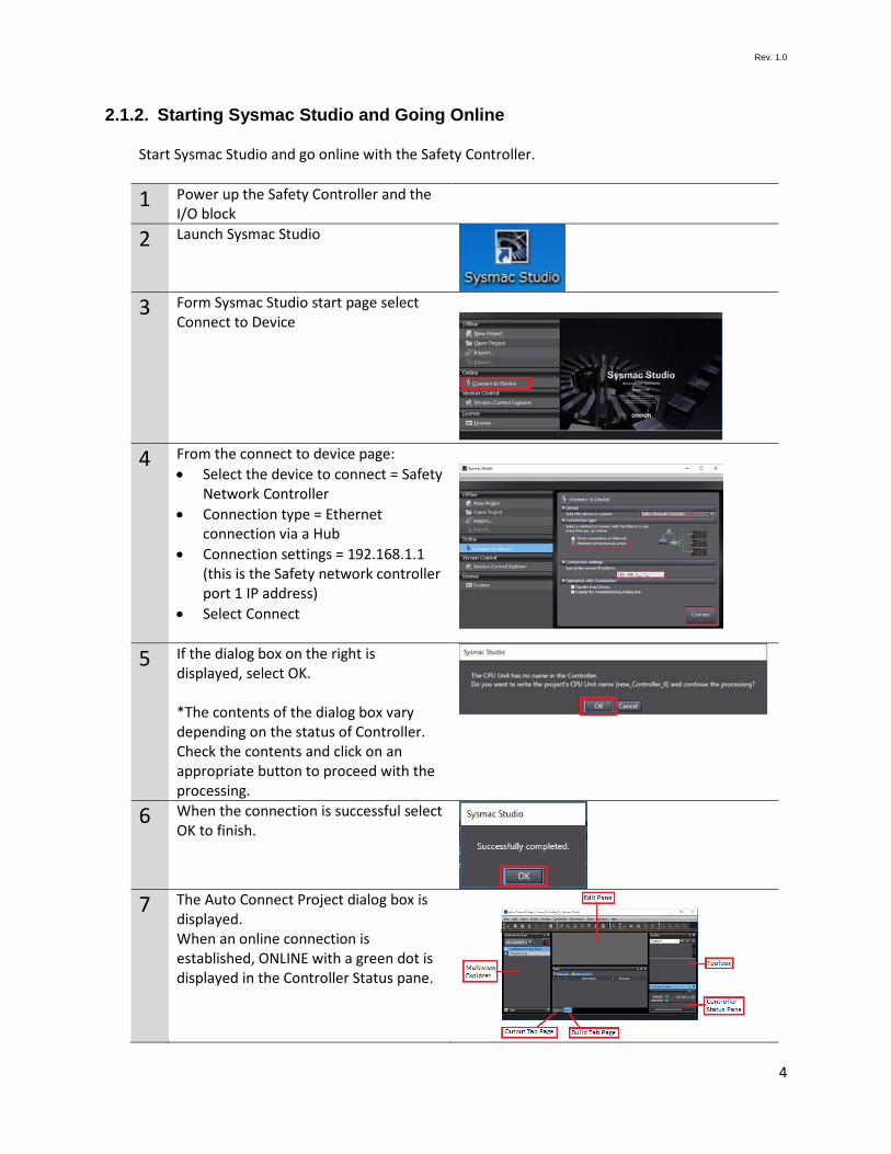
2.1.2. Starting Sysmac Studio and Going Online
Start Sysmac Studio and go online with the Safety Controller.
1 Power up the Safety Controller and the I/O block
2 Launch Sysmac Studio
3 Form Sysmac Studio start page select
Connect to Device
4 From the connect to device page:
• Select the device to connect = Safety Network Controller
• Connection type = Ethernet connection via a Hub
• Connection settings = 192.168.1.1 (this is the Safety network controller port 1 IP address)
• Select Connect
5 If the dialog box on the right is displayed, select OK. *The contents of the dialog box vary depending on the status of Controller. Check the contents and click on an appropriate button to proceed with the processing.
6 When the connection is successful select OK to finish.
7 The Auto Connect Project dialog box is
displayed. When an online connection is established, ONLINE with a green dot is displayed in the Controller Status pane.

Rev. 1.0
5
2.1.3. Creating a Safety Controller Unit Configuration
Create and setup a unit configuration for the Safety Controller.
1 Hardware configuration. • From the Multiviewer Explorer
select Configurations and Setup -> CPU/Expansion Racks
• Double click CPU Rack • From the CPU/Expansion Racks tab
right click on Unit 0 (NX-CSG320). • Select Compare and Merge with
Actual Unit Configuration. This is how Sysmac Studio check to see what is mounted to the communication control unit
2 The comparison results are displayed. Select Apply Actual Unit Configuration.
3 Check that the configuration on Sysmac
Studio and actual unit configuration match each other. Select OK to finish.
4 Go offline with the Safety Controller.
Select from the top menu Controller -> Offline

Rev. 1.0
6
2.2. Network Setting with Sysmac Studio Set the EtherNet/IP safety connection.
2.2.1. Setting the Connections
Set connection between the Safety Controller and the Omron Safety I/O Block. In the connection setting via the built-in EtherNet/IP port 2 of the Safety Controller, configure the I/O block to use as a target device.
1 From the Multiview Explorer select new_SafetyCPU0
2 Select Configurations and Setup ->
Communications -> Safety -> EtherNet/IP Safety Connection Settings. Double click on Safety Network Number Settings
3 The Safety Network Number Settings
tab page is displayed. Click on to the right of Safety Network Number (NX bus) to edit. The Safety Network Number Setting dialog box is display. The safety network number (SNN) default setting is Auto, if not, select Auto to generate the SNN for the NX bus. Select OK to finish.
4 From the Multiviewer Explorer double
click on Connection Settings (Originator).

Rev. 1.0
7
5 The Connection Settings (Originator) tab page is displayed. Click on to the right of Safety Network Number for EtherNet/IP Port 1 to edit. The Safety Network Number Settings dialog box is display. The safety network number (SNN) default setting is Auto, if not, select Auto to generate the SNN for the EtherNet/IP Port 1. Select OK to finish.
6 Select the GI module and insert under the correct Ethernet port.
7 Select the GI module and insert under Ethernet port 1.
8 Give at least one input and
output a name

Rev. 1.0
8
9 Set the GI nodes IP address Note: Use clear memory function if below does not seem to work. Changing IP address is sometimes not allowed if TUNID is set. Z400 section 6-4-3 Mode 0: 192.168.250.x x set by x16 and x1 Mode 4: DHCP see manual Z400
10 To program the GI
11 Set target node IP address –
to match the I/O block rotary set IP address

Rev. 1.0
9
12 To program each input select I/O Configuration tab -> Input.
13 To program each output
select I/O Configuration tab -> Output.
13 Transfer program to Safety
PLC (see section 2.4) Transfer setting to NX-CSG320 or NX102

Rev. 1.0
10
14 Set GI TUNID Z400 section 6-4-2

Rev. 1.0
11
2.3. Transferring Program with Sysmac Studio Transfer the Safety Network Controller and the Safety CPU program.
2.3.1. Setting Global Variables
Set global variables for the Safety Controller
1 Click Go To I/O Map in the Connection Settings (Originator) Tab page.
2 In the I/O Map click to expand.
Expand EtherNet/IP Port 1 (Originator)
3 To auto generate the variable names
right click on GI-SMD1624 and select Create Device Variable. *the auto generate variable name is the instance name + the port description (CIPOriginator_Instance_SI0)
To use user define variable names just enter the variable name in the Variable column. (Example: sensor and output are user define variable names)

Rev. 1.0
12
2.3.2. Transferring the Safety Application Data
Transfer the safety application data to the Safety Network Controller (NX-CSGxxx)
1 From the Multiview Explorer, select new_Controller_0
2 From Project -> Build Controller to check
for errors and compile the project
3 From Controller -> Online to go online to
the safety network controller
4 From Controller -> Synchronize.
The Synchronization Dialog Box is displayed. Check that the data to transfer (select NX). Select Transfer To Controller to download the application.
5 During synchronization confirmation
and warning dialog boxes will be displayed. Read and choose the option accordingly. Check the message “The Synchronization process successfully finished.” which indicate the synchronization is completed. Select Close.
Rev. 1.0
13
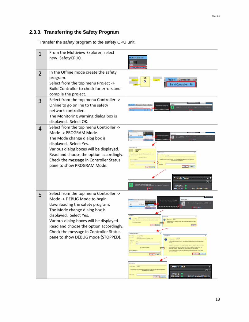
2.3.3. Transferring the Safety Program
Transfer the safety program to the safety CPU unit.
1 From the Multiview Explorer, select new_SafetyCPU0.
2 In the Offline mode create the safety
program. Select from the top menu Project -> Build Controller to check for errors and compile the project.
3 Select from the top menu Controller -> Online to go online to the safety network controller. The Monitoring warning dialog box is displayed. Select OK.
4 Select from the top menu Controller -> Mode -> PROGRAM Mode. The Mode change dialog box is displayed. Select Yes. Various dialog boxes will be displayed. Read and choose the option accordingly. Check the message in Controller Status pane to show PROGRAM Mode.
5 Select from the top menu Controller ->
Mode -> DEBUG Mode to begin downloading the safety program. The Mode change dialog box is displayed. Select Yes. Various dialog boxes will be displayed. Read and choose the option accordingly. Check the message in Controller Status pane to show DEBUG mode (STOPPED).

Rev. 1.0
14
6 Select from the top menu Controller -> Mode -> Safety Validation to validate the safety program. The Create boot application dialog box is displayed. Select Yes. The information dialog box is displayed. Select OK. The Safety Validation dialog box is displayed. Select OK.
7 Select from the top menu Controller -> Mode -> RUN Mode. The Mode change dialog box is displayed. Select Yes. Various dialog boxes will be displayed. Read and choose the option accordingly. Check the message in Controller Status pane to show RUN Mode.

Rev. 1.0
15
3. Acknowledgement • EtherNet/IP is a trademark of ODVA, INC.