Embed Size (px)
Citation preview
How to Determine the Effectiveness of Generator Differential Protection
Normann Fischer, Dale Finney, and Douglas Taylor Schweitzer Engineering Laboratories, Inc.
© 2014 IEEE. Personal use of this material is permitted. Permission from IEEE must be obtained for all other uses, in any current or future media, including reprinting/republishing this material for advertising or promotional purposes, creating new collective works, for resale or redistribution to servers or lists, or reuse of any copyrighted component of this work in other works.
This paper was presented at the 67th Annual Conference for Protective Relay Engineers and can be accessed at: http://dx.doi.org/10.1109/CPRE.2014.6799018.
For the complete history of this paper, refer to the next page.
Presented at the Southern African Power System Protection Conference
Johannesburg, South Africa November 12–14, 2014
Previously presented at the 68th Annual Georgia Tech Protective Relaying Conference, April 2014,
and 67th Annual Conference for Protective Relay Engineers, March 2014
Originally presented at the 40th Annual Western Protective Relay Conference, October 2013
1
How to Determine the Effectiveness of
Generator Differential Protection
Normann Fischer, Dale Finney, and Douglas Taylor, Schweitzer Engineering Laboratories, Inc.
Abstract—Differential protection is often touted as being The
protection for generator stator windings. In this paper, we
examine the degree of protection afforded by the various types of
differential elements (phase, negative, and zero sequence) for
stator winding faults.
To understand why and how windings fail, we need to know
how a stator is constructed, how the winding coils are made, and
how they are mounted into the stator core. This paper examines
various types of winding configurations and the makeup of the
winding insulation. We analyze how different winding failures
can be detected using the various differential elements
mentioned. Because protection elements are not only required to
be sensitive but also secure, we contrast the dependability and
security of each element. Security of any differential element
must include the performance of the primary current
transformers (CTs); therefore, we extend the discussion to setting
recommendations and CT selection rules.
Finally, the paper answers the question, How much protection
does each type of differential element provide? Knowing the
limits to performance will allow protection engineers to set the
elements for realistic sensitivity without unnecessarily risking
any security.
I. INTRODUCTION
Before protection for any piece of an electrical apparatus
can be selected, a thorough understanding of the apparatus, as
well as all of the possible failure modes of the apparatus, is
required. Rotating synchronous machines are unique in that to
provide comprehensive protection for the machines, separate
measurements and protection are required for the stator and
the rotor. This paper will concentrate on only the stator of a
generator.
The rotating magnetic field produced by the rotation of the
rotor induces voltage into the stator windings. These stator
windings are connected in series, parallel, or both depending
on the number of poles and the voltage and current rating of
the machine. Typically, a winding is made of several turns to
form a coil, and each coil occupies a slot or part of a slot in the
stator. The turns that make up the winding are not only
insulated from one another but also from the stator core. A
winding fault occurs when insulation in one of the winding
components fails. The type of insulation failure determines the
fault type. For example, if the insulation between two turns
fails, a turn-to-turn fault develops. This type of fault is
difficult to detect using conventional protection techniques
and may only be detected once the fault evolves into a turn-to-
ground fault.
What is interesting about winding faults in general is that
they can only be detected once the insulation has failed.
However, unlike in an overhead transmission line, the winding
insulation cannot be restored. Therefore, once the fault has
been detected, the machine must either be taken out of service
for a complete rewind or be temporarily repaired to keep the
machine in service until a rewind can be scheduled. This
implies that the protection is installed only to prevent
cumulative damage after the fault has been detected and does
not remove the need to repair the machine.
II. THE GENERATOR STATOR WINDING
Before trying to understand how a winding can fail and
what fault current can be generated during a fault condition, it
is useful to review how a stator is constructed. The stator
consists of three main components: the stator core, stator
windings, and insulation.
When assessing the impact of a winding-to-ground fault,
another important aspect to consider is the grounding of the
stator neutral terminal. This not only influences the magnitude
of the fault current but also determines what protection will be
required to detect such a fault.
A. Stator Core Construction
The rotational speed of the prime mover has a significant
influence on the generator construction. In all large generators,
the limiting factor is the centrifugal force on the rotor.
Generators driven by steam turbines rotate at high speeds;
consequently, the rotor is made from forged steel. Because the
nominal frequency is fixed at 50 or 60 Hz, the required rotor
speed is attained by limiting the number of poles to two or
four, which results in rotor speeds of 3,000 or 1,500 rpm at
50 Hz and 3,600 or 1,800 rpm at 60 Hz. We know that the
stator phase voltage (Vph) is proportional to the product of the
effective air-gap flux (M) and the number of turns (N) per
phase, as shown by (1).
ph MV 4.44Nƒ (1)
A large flux requires a large core area, and because
centrifugal force limits the rotor diameter to approximately
1.2 meters, a long stator core is required to provide the
required area. The core length of a large turbogenerator is
typically several meters long. For example, a large 500 MVA,
50 Hz turbogenerator with a rotor diameter of 1.2 meters has
an axial length of about 5 meters. Here, we make use of the
rule of thumb that for every megawatt, an axial length of
10 millimeters is required [1]. The stator core of a
turbogenerator is built of multiple sections of grain-oriented
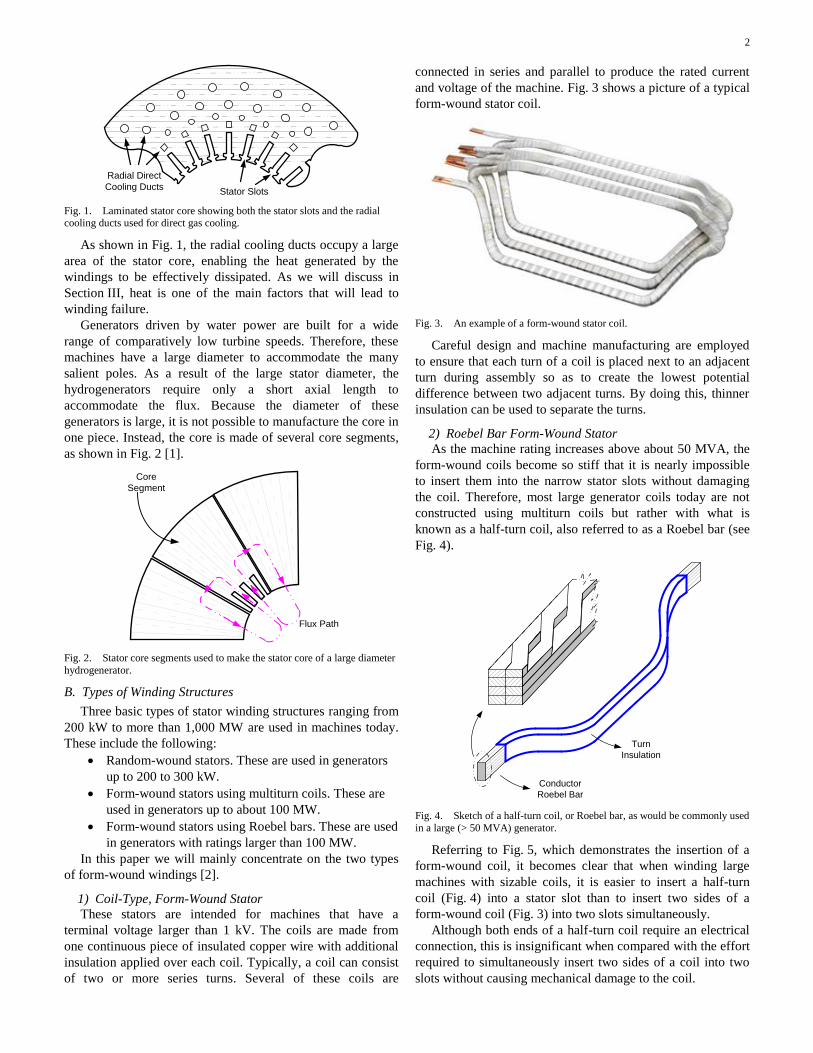
steel, as shown in Fig. 1.
2
Radial Direct
Cooling DuctsStator Slots
Fig. 1. Laminated stator core showing both the stator slots and the radial cooling ducts used for direct gas cooling.
As shown in Fig. 1, the radial cooling ducts occupy a large
area of the stator core, enabling the heat generated by the
windings to be effectively dissipated. As we will discuss in
Section III, heat is one of the main factors that will lead to
winding failure.
Generators driven by water power are built for a wide
range of comparatively low turbine speeds. Therefore, these
machines have a large diameter to accommodate the many
salient poles. As a result of the large stator diameter, the
hydrogenerators require only a short axial length to
accommodate the flux. Because the diameter of these
generators is large, it is not possible to manufacture the core in
one piece. Instead, the core is made of several core segments,
as shown in Fig. 2 [1].
Core
Segment
Flux Path
Fig. 2. Stator core segments used to make the stator core of a large diameter
hydrogenerator.
B. Types of Winding Structures
Three basic types of stator winding structures ranging from
200 kW to more than 1,000 MW are used in machines today.
These include the following:
Random-wound stators. These are used in generators
up to 200 to 300 kW.
Form-wound stators using multiturn coils. These are
used in generators up to about 100 MW.
Form-wound stators using Roebel bars. These are used
in generators with ratings larger than 100 MW.
In this paper we will mainly concentrate on the two types
of form-wound windings [2].
1) Coil-Type, Form-Wound Stator
These stators are intended for machines that have a
terminal voltage larger than 1 kV. The coils are made from
one continuous piece of insulated copper wire with additional
insulation applied over each coil. Typically, a coil can consist
of two or more series turns. Several of these coils are
connected in series and parallel to produce the rated current
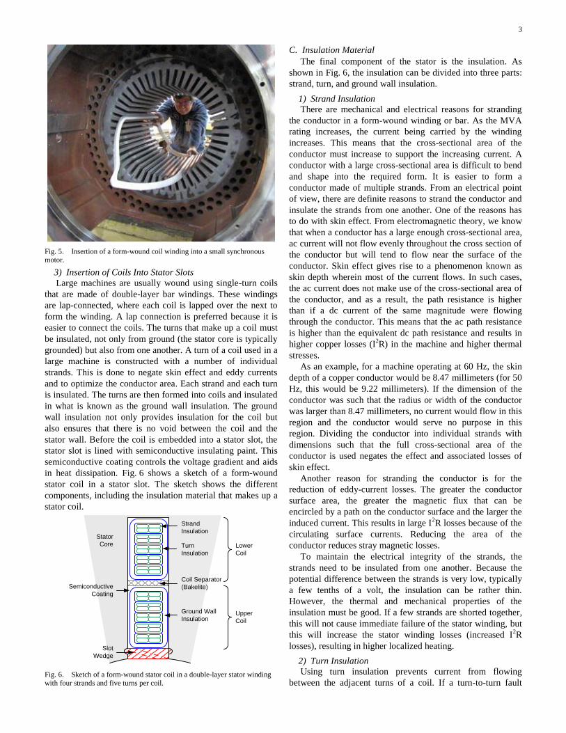
and voltage of the machine. Fig. 3 shows a picture of a typical
form-wound stator coil.
Fig. 3. An example of a form-wound stator coil.
Careful design and machine manufacturing are employed
to ensure that each turn of a coil is placed next to an adjacent
turn during assembly so as to create the lowest potential
difference between two adjacent turns. By doing this, thinner
insulation can be used to separate the turns.
2) Roebel Bar Form-Wound Stator
As the machine rating increases above about 50 MVA, the
form-wound coils become so stiff that it is nearly impossible
to insert them into the narrow stator slots without damaging
the coil. Therefore, most large generator coils today are not
constructed using multiturn coils but rather with what is
known as a half-turn coil, also referred to as a Roebel bar (see
Fig. 4).
Conductor
Roebel Bar
Turn
Insulation
Fig. 4. Sketch of a half-turn coil, or Roebel bar, as would be commonly used
in a large (> 50 MVA) generator.
Referring to Fig. 5, which demonstrates the insertion of a
form-wound coil, it becomes clear that when winding large
machines with sizable coils, it is easier to insert a half-turn
coil (Fig. 4) into a stator slot than to insert two sides of a
form-wound coil (Fig. 3) into two slots simultaneously.
Although both ends of a half-turn coil require an electrical
connection, this is insignificant when compared with the effort
required to simultaneously insert two sides of a coil into two
slots without causing mechanical damage to the coil.
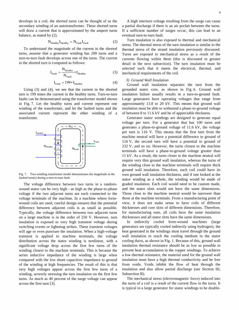
3
Fig. 5. Insertion of a form-wound coil winding into a small synchronous motor.
3) Insertion of Coils Into Stator Slots
Large machines are usually wound using single-turn coils
that are made of double-layer bar windings. These windings
are lap-connected, where each coil is lapped over the next to
form the winding. A lap connection is preferred because it is
easier to connect the coils. The turns that make up a coil must
be insulated, not only from ground (the stator core is typically
grounded) but also from one another. A turn of a coil used in a
large machine is constructed with a number of individual
strands. This is done to negate skin effect and eddy currents
and to optimize the conductor area. Each strand and each turn
is insulated. The turns are then formed into coils and insulated
in what is known as the ground wall insulation. The ground
wall insulation not only provides insulation for the coil but
also ensures that there is no void between the coil and the
stator wall. Before the coil is embedded into a stator slot, the
stator slot is lined with semiconductive insulating paint. This
semiconductive coating controls the voltage gradient and aids
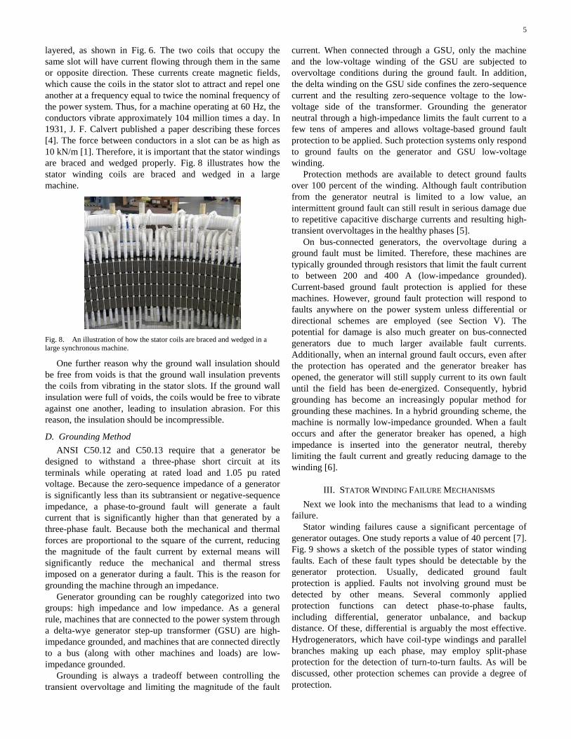
in heat dissipation. Fig. 6 shows a sketch of a form-wound
stator coil in a stator slot. The sketch shows the different
components, including the insulation material that makes up a
stator coil.
Strand
Insulation
Turn
Insulation
Ground Wall
Insulation
Slot
Wedge
Semiconductive
Coating
Coil Separator
(Bakelite)
Lower
Coil
Upper
Coil
Stator
Core
Fig. 6. Sketch of a form-wound stator coil in a double-layer stator winding
with four strands and five turns per coil.
C. Insulation Material
The final component of the stator is the insulation. As
shown in Fig. 6, the insulation can be divided into three parts:
strand, turn, and ground wall insulation.
1) Strand Insulation
There are mechanical and electrical reasons for stranding
the conductor in a form-wound winding or bar. As the MVA
rating increases, the current being carried by the winding
increases. This means that the cross-sectional area of the
conductor must increase to support the increasing current. A
conductor with a large cross-sectional area is difficult to bend
and shape into the required form. It is easier to form a
conductor made of multiple strands. From an electrical point
of view, there are definite reasons to strand the conductor and
insulate the strands from one another. One of the reasons has
to do with skin effect. From electromagnetic theory, we know
that when a conductor has a large enough cross-sectional area,
ac current will not flow evenly throughout the cross section of
the conductor but will tend to flow near the surface of the
conductor. Skin effect gives rise to a phenomenon known as
skin depth wherein most of the current flows. In such cases,
the ac current does not make use of the cross-sectional area of
the conductor, and as a result, the path resistance is higher
than if a dc current of the same magnitude were flowing
through the conductor. This means that the ac path resistance
is higher than the equivalent dc path resistance and results in
higher copper losses (I2R) in the machine and higher thermal
stresses.
As an example, for a machine operating at 60 Hz, the skin
depth of a copper conductor would be 8.47 millimeters (for 50
Hz, this would be 9.22 millimeters). If the dimension of the
conductor was such that the radius or width of the conductor
was larger than 8.47 millimeters, no current would flow in this
region and the conductor would serve no purpose in this
region. Dividing the conductor into individual strands with
dimensions such that the full cross-sectional area of the
conductor is used negates the effect and associated losses of
skin effect.
Another reason for stranding the conductor is for the
reduction of eddy-current losses. The greater the conductor
surface area, the greater the magnetic flux that can be
encircled by a path on the conductor surface and the larger the
induced current. This results in large I2R losses because of the
circulating surface currents. Reducing the area of the
conductor reduces stray magnetic losses.
To maintain the electrical integrity of the strands, the
strands need to be insulated from one another. Because the
potential difference between the strands is very low, typically
a few tenths of a volt, the insulation can be rather thin.
However, the thermal and mechanical properties of the
insulation must be good. If a few strands are shorted together,
this will not cause immediate failure of the stator winding, but
this will increase the stator winding losses (increased I2R
losses), resulting in higher localized heating.
2) Turn Insulation
Using turn insulation prevents current from flowing
between the adjacent turns of a coil. If a turn-to-turn fault
4
develops in a coil, the shorted turns can be thought of as the
secondary winding of an autotransformer. These shorted turns
will draw a current that is approximated by the ampere turns
balance, as stated by (2).
Healthy Healthy Fault FaultN I N I (2)
To understand the magnitude of the current in the shorted
turns, assume that a generator winding has 200 turns and a
turn-to-turn fault develops across one of the turns. The current
in the shorted turn is computed as follows:
Healthy
Fault Healthy
Fault
NI • I
N (3)
Fault HealthyI 199• I (4)
Using (3) and (4), we see that the current in the shorted
turn is 199 times the current in the healthy turns. Turn-to-turn
faults can be demonstrated using the transformer model shown
in Fig. 7. Let the healthy turns and current represent one
winding of the transformer, and let the faulted turns and the
associated current represent the other winding of a
transformer.
M
NHealthy
IHealthy
IFault
NFault
Fig. 7. Two-winding transformer model demonstrates the magnitude in the faulted turn(s) during a turn-to-turn fault.
The voltage difference between two turns in a random-
wound stator can be very high—as high as the phase-to-phase
voltage if the two adjacent turns are each connected to the
voltage terminals of the machine. In a machine where form-
wound coils are used, careful design ensures that the potential
difference between adjacent coils is as small as possible.
Typically, the voltage difference between two adjacent turns
on a large machine is in the order of 250 V. However, turn
insulation is exposed to very high transient voltage during
switching events or lightning strikes. These transient voltages
will age or even puncture the insulation. When a high-voltage
transient is applied to machine terminals, the voltage
distribution across the stator winding is nonlinear, with a
significant voltage drop across the first few turns of the
winding closest to the machine terminals. This is because the
series inductive impedance of the winding is large when
compared with the low shunt capacitive impedance to ground
of the winding at high frequencies. The result of this is that
very high voltages appear across the first few turns of a
winding, severely stressing the turn insulation on the first few
turns. As much as 40 percent of the surge voltage can appear
across the first turn [3].
A high interturn voltage resulting from the surge can cause
a partial discharge if there is an air pocket between the turns.
If a sufficient number of surges occur, this can lead to an
eventual turn-to-turn fault.
Turn insulation is also exposed to thermal and mechanical
stress. The thermal stress of the turn insulation is similar to the
thermal stress of the strand insulation previously discussed.
Turns are exposed to mechanical stress as a result of the
currents flowing within them (this is discussed in greater
detail in the next subsection). The turn insulation must be
selected such that it meets the electrical, thermal, and
mechanical requirements of the coil.
3) Ground Wall Insulation
Ground wall insulation separates the turn from the
grounded stator core, as shown in Fig. 6. Ground wall
insulation failure usually results in a turn-to-ground fault.
Large generators have operating voltages that range from
approximately 13.8 to 20 kV. This means that ground wall
insulation must be able to withstand a phase-to-ground voltage
of between 8 to 11.6 kV and be of appreciable thickness.
Generator stator windings are designed to generate equal
voltage per turn. For a generator that has 100 turns and
generates a phase-to-ground voltage of 11.6 kV, the voltage
per turn is 116 V. This means that the first turn from the
machine neutral will have a potential difference to ground of
116 V, the second turn will have a potential to ground of
232 V, and so on. However, the turns closest to the machine
terminals will have a phase-to-ground voltage greater than
11 kV. As a result, the turns closer to the machine neutral will
require very thin ground wall insulation, whereas the turns of
the winding close to the machine terminals will require thick
ground wall insulation. Therefore, each coil could have its
own ground wall insulation thickness, and if one looked at the
stator winding as a whole, the winding would be made of
graded insulation. Each coil would need to be custom made,
and the stator slots would not have the same dimensions.
Those close to the machine neutral would be narrower than
those at the machine terminals. From a manufacturing point of
view, it does not make sense to have coils of different
thicknesses and core slots of different dimensions. Therefore,
for manufacturing ease, all coils have the same insulation
thicknesses and all stator slots have the same dimensions.
In indirectly cooled form-wound machines (large
generators are typically cooled indirectly using hydrogen), the
heat generated in the windings must travel through the ground
wall insulation to reach the cooling medium in the stator
cooling ducts, as shown in Fig. 1. Because of this, ground wall
insulation thermal resistance should be as low as possible to
prevent heat accumulation in the copper windings. To achieve
a low thermal resistance, the material used for the ground wall
insulation must have a high thermal conductivity and be free
from voids. Voids inhibit the flow of heat through the
insulation and also allow partial discharge (see Section III,
Subsection B).
The mechanical stress (electromagnetic force) induced into
the turns of a coil is a result of the current flow in the turns. It
is typical in a large generator for stator windings to be double-
5
layered, as shown in Fig. 6. The two coils that occupy the
same slot will have current flowing through them in the same
or opposite direction. These currents create magnetic fields,
which cause the coils in the stator slot to attract and repel one
another at a frequency equal to twice the nominal frequency of
the power system. Thus, for a machine operating at 60 Hz, the
conductors vibrate approximately 104 million times a day. In
1931, J. F. Calvert published a paper describing these forces
[4]. The force between conductors in a slot can be as high as
10 kN/m [1]. Therefore, it is important that the stator windings
are braced and wedged properly. Fig. 8 illustrates how the
stator winding coils are braced and wedged in a large
machine.
Fig. 8. An illustration of how the stator coils are braced and wedged in a large synchronous machine.
One further reason why the ground wall insulation should
be free from voids is that the ground wall insulation prevents
the coils from vibrating in the stator slots. If the ground wall
insulation were full of voids, the coils would be free to vibrate
against one another, leading to insulation abrasion. For this
reason, the insulation should be incompressible.
D. Grounding Method
ANSI C50.12 and C50.13 require that a generator be
designed to withstand a three-phase short circuit at its
terminals while operating at rated load and 1.05 pu rated
voltage. Because the zero-sequence impedance of a generator
is significantly less than its subtransient or negative-sequence
impedance, a phase-to-ground fault will generate a fault
current that is significantly higher than that generated by a
three-phase fault. Because both the mechanical and thermal
forces are proportional to the square of the current, reducing
the magnitude of the fault current by external means will
significantly reduce the mechanical and thermal stress
imposed on a generator during a fault. This is the reason for
grounding the machine through an impedance.
Generator grounding can be roughly categorized into two
groups: high impedance and low impedance. As a general
rule, machines that are connected to the power system through
a delta-wye generator step-up transformer (GSU) are high-
impedance grounded, and machines that are connected directly
to a bus (along with other machines and loads) are low-
impedance grounded.
Grounding is always a tradeoff between controlling the
transient overvoltage and limiting the magnitude of the fault
current. When connected through a GSU, only the machine
and the low-voltage winding of the GSU are subjected to
overvoltage conditions during the ground fault. In addition,
the delta winding on the GSU side confines the zero-sequence
current and the resulting zero-sequence voltage to the low-
voltage side of the transformer. Grounding the generator
neutral through a high-impedance limits the fault current to a
few tens of amperes and allows voltage-based ground fault
protection to be applied. Such protection systems only respond
to ground faults on the generator and GSU low-voltage
winding.
Protection methods are available to detect ground faults
over 100 percent of the winding. Although fault contribution
from the generator neutral is limited to a low value, an
intermittent ground fault can still result in serious damage due
to repetitive capacitive discharge currents and resulting high-
transient overvoltages in the healthy phases [5].
On bus-connected generators, the overvoltage during a
ground fault must be limited. Therefore, these machines are
typically grounded through resistors that limit the fault current
to between 200 and 400 A (low-impedance grounded).
Current-based ground fault protection is applied for these
machines. However, ground fault protection will respond to
faults anywhere on the power system unless differential or
directional schemes are employed (see Section V). The
potential for damage is also much greater on bus-connected
generators due to much larger available fault currents.
Additionally, when an internal ground fault occurs, even after
the protection has operated and the generator breaker has
opened, the generator will still supply current to its own fault
until the field has been de-energized. Consequently, hybrid
grounding has become an increasingly popular method for
grounding these machines. In a hybrid grounding scheme, the
machine is normally low-impedance grounded. When a fault
occurs and after the generator breaker has opened, a high
impedance is inserted into the generator neutral, thereby
limiting the fault current and greatly reducing damage to the
winding [6].
III. STATOR WINDING FAILURE MECHANISMS
Next we look into the mechanisms that lead to a winding
failure.
Stator winding failures cause a significant percentage of
generator outages. One study reports a value of 40 percent [7].
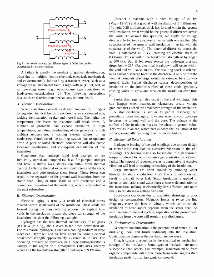
Fig. 9 shows a sketch of the possible types of stator winding
faults. Each of these fault types should be detectable by the
generator protection. Usually, dedicated ground fault
protection is applied. Faults not involving ground must be
detected by other means. Several commonly applied
protection functions can detect phase-to-phase faults,
including differential, generator unbalance, and backup
distance. Of these, differential is arguably the most effective.
Hydrogenerators, which have coil-type windings and parallel
branches making up each phase, may employ split-phase
protection for the detection of turn-to-turn faults. As will be
discussed, other protection schemes can provide a degree of
protection.
6
N
A
B
C
Phase-to-Phase
Phase-to-Ground
Turn-to-Turn
Fig. 9. A sketch showing the different types of faults that can be
experienced by a stator winding.
A failure is usually the product of gradual deterioration,
often due to multiple factors (thermal, electrical, mechanical,
and environmental), followed by a transient event, such as a
voltage surge, an external fault, a high-voltage (HiPot) test, or
an operating error (e.g., out-of-phase synchronization or
inadvertent energization) [2]. The following subsections
discuss these deterioration mechanisms in more detail.
A. Thermal Deterioration
When insulation exceeds its design temperature, it begins
to degrade; chemical bonds break down at an accelerated rate,
making the insulation weaker and more brittle. The higher the
temperature, the faster the insulation will break down. A
number of problems can expose insulation to high
temperatures, including overloading of the generator, a high
ambient temperature, a cooling system failure, or an
inadvertent shutdown of the cooling system due to operator
error. A poor or failed electrical connection will also create
localized overheating and consequent degradation of the
insulation.
Generators that undergo rapid load changes or are
frequently started and stopped (such as for pumped storage)
and have relatively long stators can suffer from thermal
cycling. Differing thermal expansion coefficients of the coils,
insulation, and core produce shear forces. These forces can
result in the separation of the ground wall insulation from the
stator core. This, in turn, leads to slot discharge and a
consequent breakdown of the insulation, which is described in
the next subsection.
B. Electrical Deterioration
Electrical aging is usually a result of electrical stress
created within small voids of the insulation. These voids are
formed during the manufacturing process. To explain how
voids in the insulation impact the electrical strength of the
insulation, consider the following example.
Hydrogen has the best thermal conductivity of all gases
(0.168 W/(m • K)), about seven to ten times better than air.
For this reason, hydrogen is used as a cooling medium in large
machines. Hydrogen and air have about the same electrical
breakdown strength, approximately 3 kV/mm at 100 kPa. The
operating pressure of hydrogen in a large turbogenerator is
usually in the region of 3 atmospheres (300 kPa), thereby
increasing the breakdown strength of hydrogen to 9 kV/mm.
Consider a machine with a rated voltage of 21 kV
(VLN 12 kV) and a ground wall insulation of 5 millimeters.
If a void 0.25 millimeters thick has formed within the ground
wall insulation, what would be the potential difference across
the void? To answer this question, we apply the voltage
divider rule for two capacitors in series with one another (the
capacitance of the ground wall insulation in series with the
capacitance of the void). The potential difference across the
void is calculated at 2 kV, creating an electric stress of
8 kV/mm. This is within the breakdown strength of hydrogen
at 300 kPa. But, if for some reason the hydrogen pressure
drops below 267 kPa, electrical breakdown will occur within
the void and will cause an arc. The resulting spark is referred
to as partial discharge because the discharge is only within the
void. A complete discharge would, in essence, be a turn-to-
ground fault. Partial discharge causes decomposition of
insulation on the interior surface of these voids, gradually
causing voids to grow and weaken the insulation over time
[8].
Partial discharge can also occur in the end windings. This
can happen when inadequate clearances create voltage
gradients that exceed the breakdown strength of the insulation.
A slot discharge is similar to partial discharge but
potentially more damaging. It occurs when a void develops
between the ground wall and the core. The voltage at the
surface of the insulation rises to the phase-to-ground value.
This results in an arc, which breaks down the insulation at the
surface, eventually resulting in an insulation failure.
C. Mechanical Deterioration
Inadequate bracing of the end windings due to poor design
or construction can lead to excessive vibration in the end
windings. The bracing may also loosen due to high transient
torque produced by out-of-phase synchronization or close-in
faults. The impact of repeated events is cumulative. Excessive
vibration will lead to wearing or cracking of the insulation.
Large machines are often cooled by pumping water
through the stator conductors. High levels of vibration can
result in a small water leak. Stator insulation is applied in
layers or laminations and water ingress causes delamination of
the insulation, making it electrically less effective and more
likely to fail during a voltage transient.
Loose coils can occur due to insulation shrinkage or poor
design or construction. Magnetic forces at twice the line
frequency cause the bars to vibrate, which can cause the
insulation to wear and/or separate from the stator core. As
with the case of thermal cycling, separation of the ground wall
insulation from the core will result in slot discharges.
D. Environmental Deterioration
Generator contamination is the penetration of water, oil, or
dust (e.g., coal and brush sediment) into the insulation.
Contamination degrades the insulation in two ways.
First, it causes a reduction in the electrical or mechanical
strength of the insulation. Some types of insulation are more
susceptible than others. For example, insulation made from
organic compounds will suffer more from water ingress than
insulation made from an inorganic compound.
7
Secondly, contamination provides a medium for surface
tracking, primarily in the end winding. Surface contamination
creates a path for small capacitive currents driven by potential
differences within a phase or between phases. These currents
lead to surface discharge in the air adjacent to the surface and
the formation of carbon tracking. The low-impedance paths
formed by these tracks can lead to a phase-to-phase fault or a
turn-to-turn fault.
IV. EVOLVING FAULTS
Ideally, any insulation failure should be quickly detected
by protection functions. Failure to detect a fault early
increases its duration and can result in its evolution into a
more potentially damaging fault type. The following are
examples of how generator faults can evolve without proper
effective protection.
As outlined in Section II, turn-to-turn faults are possible in
windings constructed from multiturn coils. One survey found
that only about 25 percent of the total surface area of the
insulation separates a conductor from ground or from another
phase in this type of winding [9]. The remaining 75 percent of
the insulation is between turns. Therefore, the potential for
turn-to-turn faults is high. When a turn-to-turn fault occurs,
the current flowing in the shorted turn can be significantly
higher than the nominal current of the machine (as shown in
Section II, Subsection C). Without effective turn-to-turn fault
protection, this current will quickly burn insulation and melt
conductors, resulting in a phase-to-phase or phase-to-ground
fault.
Similarly, a ground fault can evolve into a much more
damaging phase-to-phase fault. For instance, one of the
deterioration mechanisms previously described could cause a
weakening of the insulation in the vicinity of the stator
neutral. Here, the voltage to ground will be low. Without
effective ground-fault protection for 100 percent of the
winding, this problem could go undetected. If a ground fault
develops near the terminals, the neutral point voltage will rise
to the phase-to-neutral voltage. The previously weakened
insulation near the neutral will break down, resulting in a
much more severe fault.
A third possibility is an intermittent ground fault. Due to
inherent delays in ground fault protection schemes, the fault
may go undetected. The successive transient overvoltages
occurring at the inception of each arc could lead to a ground
fault on a second phase.
V. DIFFERENTIAL PROTECTION SCHEMES
Differential protection is one of the main protection
elements responsible for detecting the failures described in
Section III. Generator differential protection schemes are
designed to detect faults by comparing the current following
into and out of the stator. A variety of schemes is possible.
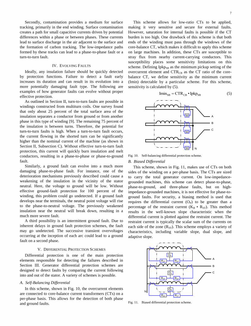
A. Self-Balancing Differential
In this scheme, shown in Fig. 10, the overcurrent elements
are connected to core-balance current transformers (CTs) on a
per-phase basis. This allows for the detection of both phase
and ground faults.
This scheme allows for low-ratio CTs to be applied,
making it very sensitive and secure for external faults.
However, saturation for internal faults is possible if the CT
burden is too high. One drawback of this scheme is that both
ends of the winding must pass through the windows of the
core-balance CT, which makes it difficult to apply this scheme
on large machines. In addition, these CTs are susceptible to
stray flux from nearby current-carrying conductors. This
susceptibility places some sensitivity limitations on this
scheme. Defining IpkpSB as the minimum pickup setting of the
overcurrent element and CTRCB as the CT ratio of the core-
balance CT, we define sensitivity as the minimum current
(Imin) detectable by a particular scheme. For this scheme,
sensitivity is calculated by (5).
SB CB SBImin CTR • Ipkp (5)
50
50
50
A
B
C
N
Fig. 10. Self-balancing differential protection scheme.
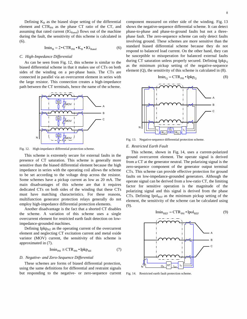
B. Biased Differential
This scheme, shown in Fig. 11, makes use of CTs on both
sides of the winding on a per-phase basis. The CTs are sized
to carry the total generator current. On low-impedance-
grounded machines, this scheme can detect phase-to-phase,
phase-to-ground, and three-phase faults, but on high-
impedance-grounded machines, it is not effective for phase-to-
ground faults. For security, a biasing method is used that
requires the differential current (OP) to be greater than a
percentage of the restraint current (KB • RST). This method
results in the well-known slope characteristic when the
differential current is plotted against the restraint current. The
restraint current is typically the scalar sum of the currents on
each side of the zone (RST). This scheme employs a variety of
characteristics, including variable slope, dual slope, and
adaptive slope.
A
B
C
N
RST
OP
OP
RST
RST RST
RST RST
OP
Fig. 11. Biased differential protection scheme.
8
Defining KB as the biased slope setting of the differential
element and CTRPH as the phase CT ratio of the CT, and
assuming that rated current (IGRated) flows out of the machine
during the fault, the sensitivity of this scheme is calculated in
(6).
B PH B RatedImin 2•CTR • K • IG (6)
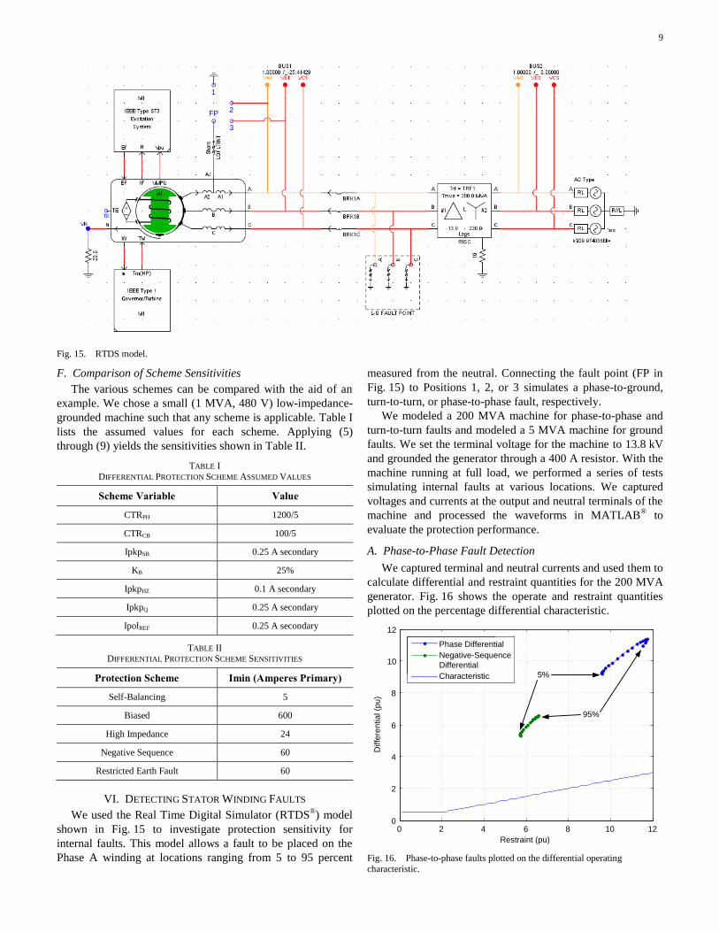
C. High-Impedance Differential
As can be seen from Fig. 12, this scheme is similar to the
biased differential scheme in that it makes use of CTs on both
sides of the winding on a per-phase basis. The CTs are
connected in parallel via an overcurrent element in series with
the large resistor. This connection creates a high-impedance
path between the CT terminals, hence the name of the scheme.
A
B
C
N
50MOV
50MOV
50MOV
Fig. 12. High-impedance differential protection scheme.
This scheme is extremely secure for external faults in the
presence of CT saturation. This scheme is generally more
sensitive than the biased differential element because the high
impedance in series with the operating coil allows the scheme
to be set according to the voltage drop across the resistor.
Some schemes have a pickup current as low as 20 mA. The
main disadvantages of this scheme are that it requires
dedicated CTs on both sides of the winding that these CTs
must have matching characteristics. For these reasons,
multifunction generator protection relays generally do not
employ high-impedance differential protection elements.
Another disadvantage is the fact that a shorted CT disables
the scheme. A variation of this scheme uses a single
overcurrent element for restricted earth fault detection on low-
impedance-grounded machines.
Defining IpkpHZ as the operating current of the overcurrent
element and neglecting CT excitation current and metal oxide
varistor (MOV) current, the sensitivity of this scheme is
approximated in (7).
PH PH HZImin CTR • Ipkp (7)
D. Negative- and Zero-Sequence Differential
These schemes are forms of biased differential protection,
using the same definitions for differential and restraint signals
but responding to the negative- or zero-sequence current
component measured on either side of the winding. Fig. 13
shows the negative-sequence differential scheme. It can detect
phase-to-phase and phase-to-ground faults but not a three-
phase fault. The zero-sequence scheme can only detect faults
involving ground. These schemes are more sensitive than the
standard biased differential scheme because they do not
respond to balanced load current. On the other hand, they can
be susceptible to misoperation for balanced external faults
during CT saturation unless properly secured. Defining IpkpQ
as the minimum pickup setting of the negative-sequence
element (Q), the sensitivity of this scheme is calculated in (8).
Q PH QImin CTR • Ipkp (8)
A
B
C
NOP
RST
I2RST
I2
Fig. 13. Negative-sequence differential protection scheme.
E. Restricted Earth Fault
This scheme, shown in Fig. 14, uses a current-polarized
ground overcurrent element. The operate signal is derived
from a CT at the generator neutral. The polarizing signal is the
zero-sequence component of the generator output terminal
CTs. This scheme can provide effective protection for ground
faults on low-impedance-grounded generators. Although the
operate signal can be derived from a low-ratio CT, the limiting
factor for sensitive operation is the magnitude of the
polarizing signal and this signal is derived from the phase
CTs. Defining IpolREF as the minimum pickup setting of the
element, the sensitivity of the scheme can be calculated using
(9).
REF PH REFImin CTR • Ipol (9)
A
B
C
N67 IpolOP
IG
Fig. 14. Restricted earth fault protection scheme.
9
1
2
3
FP
Fig. 15. RTDS model.
F. Comparison of Scheme Sensitivities
The various schemes can be compared with the aid of an
example. We chose a small (1 MVA, 480 V) low-impedance-
grounded machine such that any scheme is applicable. Table I
lists the assumed values for each scheme. Applying (5)
through (9) yields the sensitivities shown in Table II.
TABLE I
DIFFERENTIAL PROTECTION SCHEME ASSUMED VALUES
Scheme Variable Value
CTRPH 1200/5
CTRCB 100/5
IpkpSB 0.25 A secondary
KB 25%
IpkpHZ 0.1 A secondary
IpkpQ 0.25 A secondary
IpolREF 0.25 A secondary
TABLE II DIFFERENTIAL PROTECTION SCHEME SENSITIVITIES
Protection Scheme Imin (Amperes Primary)
Self-Balancing 5
Biased 600
High Impedance 24
Negative Sequence 60
Restricted Earth Fault 60
VI. DETECTING STATOR WINDING FAULTS
We used the Real Time Digital Simulator (RTDS®) model
shown in Fig. 15 to investigate protection sensitivity for
internal faults. This model allows a fault to be placed on the
Phase A winding at locations ranging from 5 to 95 percent
measured from the neutral. Connecting the fault point (FP in
Fig. 15) to Positions 1, 2, or 3 simulates a phase-to-ground,
turn-to-turn, or phase-to-phase fault, respectively.
We modeled a 200 MVA machine for phase-to-phase and
turn-to-turn faults and modeled a 5 MVA machine for ground
faults. We set the terminal voltage for the machine to 13.8 kV
and grounded the generator through a 400 A resistor. With the
machine running at full load, we performed a series of tests
simulating internal faults at various locations. We captured
voltages and currents at the output and neutral terminals of the
machine and processed the waveforms in MATLAB®
to
evaluate the protection performance.
A. Phase-to-Phase Fault Detection
We captured terminal and neutral currents and used them to
calculate differential and restraint quantities for the 200 MVA
generator. Fig. 16 shows the operate and restraint quantities
plotted on the percentage differential characteristic.
0 2 4 6 8 10 120
2
4
6
8
10
12
Phase Differential
Negative-Sequence
Differential
Characteristic
Diffe
ren
tia
l (p
u)
Restraint (pu)
5%
95%
Fig. 16. Phase-to-phase faults plotted on the differential operating
characteristic.
10
We chose a minimum pickup of 0.5 pu for the operate
current and selected a slope of 25 percent (see Section VIII).
Note that the locus of operating points lies well inside the
operating region of the characteristic for both the phase and
negative-sequence differential. The differential currents
decrease as the fault point moves toward the neutral. Because
the model allows for internal faults only on one phase, it was
not possible to simulate phase-to-phase faults at any possible
location on the winding (for instance 10 percent of Phase A to
10 percent of Phase B). However, one may assume a
continuation of the locus toward the restraint region as the
fault point moves toward neutral on the second phase.
Quantities are plotted in per unit of the generator-rated
current, which simulates CTs sized for generator-rated current.
Increasing the CT ratio has the effect of moving the entire
locus down and to the left, resulting in a decrease of the
element sensitivity.
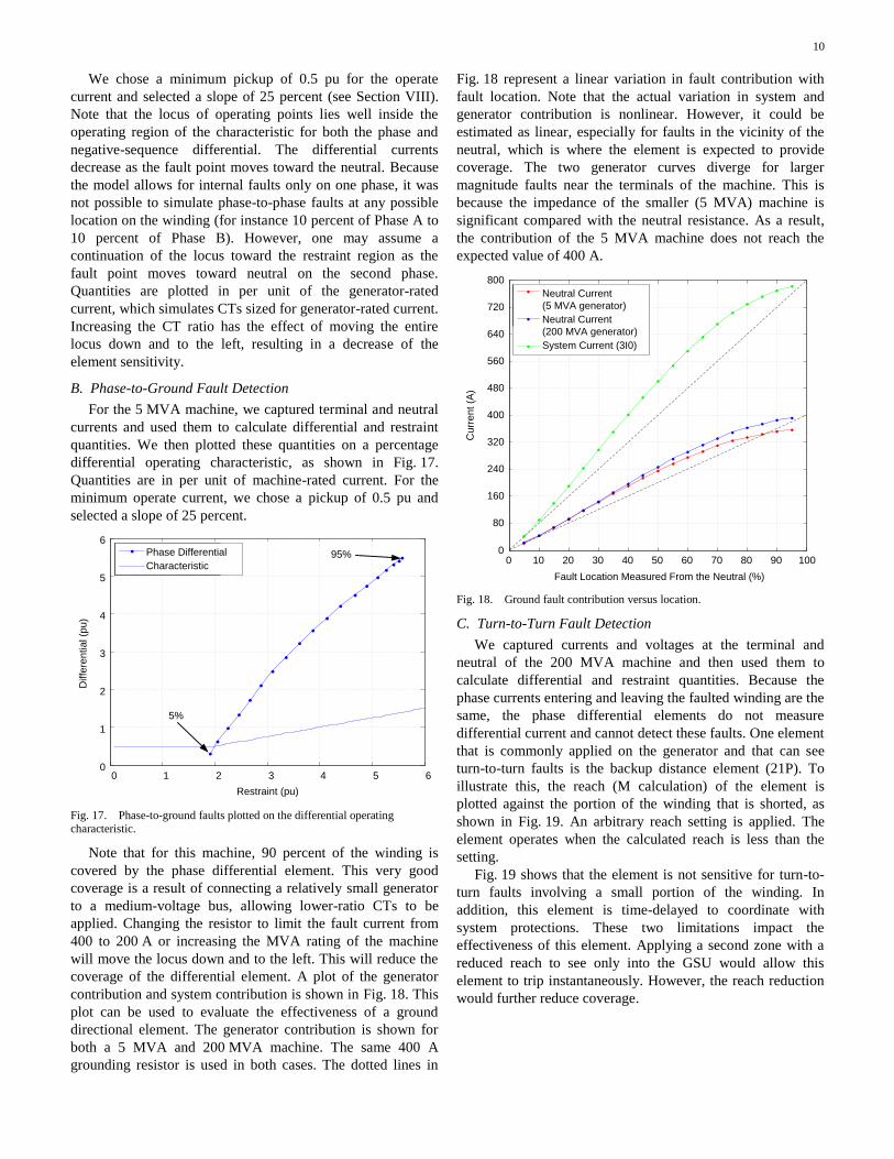
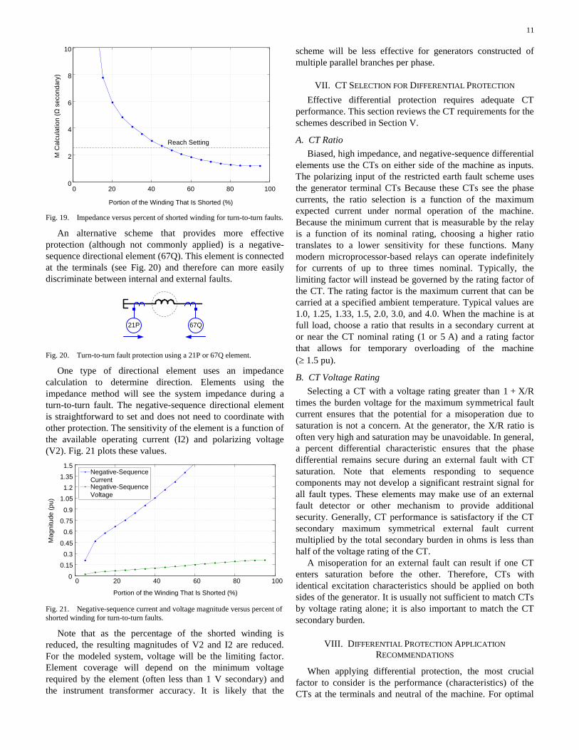
B. Phase-to-Ground Fault Detection
For the 5 MVA machine, we captured terminal and neutral
currents and used them to calculate differential and restraint
quantities. We then plotted these quantities on a percentage
differential operating characteristic, as shown in Fig. 17.
Quantities are in per unit of machine-rated current. For the
minimum operate current, we chose a pickup of 0.5 pu and
selected a slope of 25 percent.
0 1 2 3 4 5 60
1
2
3
4
5
6
Phase Differential
Characteristic
Diffe
ren
tia
l (p
u)
Restraint (pu)
5%
95%
Fig. 17. Phase-to-ground faults plotted on the differential operating characteristic.
Note that for this machine, 90 percent of the winding is
covered by the phase differential element. This very good
coverage is a result of connecting a relatively small generator
to a medium-voltage bus, allowing lower-ratio CTs to be
applied. Changing the resistor to limit the fault current from
400 to 200 A or increasing the MVA rating of the machine
will move the locus down and to the left. This will reduce the
coverage of the differential element. A plot of the generator
contribution and system contribution is shown in Fig. 18. This
plot can be used to evaluate the effectiveness of a ground
directional element. The generator contribution is shown for
both a 5 MVA and 200 MVA machine. The same 400 A
grounding resistor is used in both cases. The dotted lines in
Fig. 18 represent a linear variation in fault contribution with
fault location. Note that the actual variation in system and
generator contribution is nonlinear. However, it could be
estimated as linear, especially for faults in the vicinity of the
neutral, which is where the element is expected to provide
coverage. The two generator curves diverge for larger
magnitude faults near the terminals of the machine. This is
because the impedance of the smaller (5 MVA) machine is
significant compared with the neutral resistance. As a result,
the contribution of the 5 MVA machine does not reach the
expected value of 400 A.
0 10 20 30 40 50 60 70 80 90 1000
80
160
240
320
400
480
560
640
720
800
Neutral Current
(5 MVA generator)
Neutral Current
(200 MVA generator)
System Current (3I0)
Cu
rre
nt (A
)
Fault Location Measured From the Neutral (%)
Fig. 18. Ground fault contribution versus location.
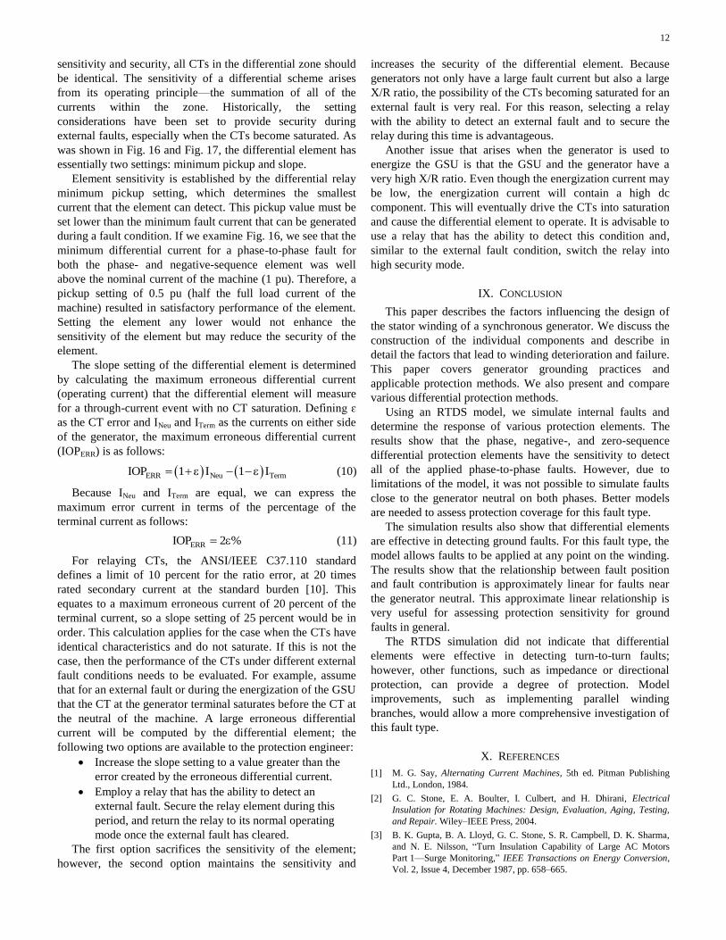
C. Turn-to-Turn Fault Detection
We captured currents and voltages at the terminal and
neutral of the 200 MVA machine and then used them to
calculate differential and restraint quantities. Because the
phase currents entering and leaving the faulted winding are the
same, the phase differential elements do not measure
differential current and cannot detect these faults. One element
that is commonly applied on the generator and that can see
turn-to-turn faults is the backup distance element (21P). To
illustrate this, the reach (M calculation) of the element is
plotted against the portion of the winding that is shorted, as
shown in Fig. 19. An arbitrary reach setting is applied. The
element operates when the calculated reach is less than the
setting.
Fig. 19 shows that the element is not sensitive for turn-to-
turn faults involving a small portion of the winding. In
addition, this element is time-delayed to coordinate with
system protections. These two limitations impact the
effectiveness of this element. Applying a second zone with a
reduced reach to see only into the GSU would allow this
element to trip instantaneously. However, the reach reduction
would further reduce coverage.
11
0 20 40 60 80 1000
2
4
6
8
10M
Ca
lcu
latio
n (
Ω s
eco
nd
ary
)
Portion of the Winding That Is Shorted (%)
Reach Setting
Fig. 19. Impedance versus percent of shorted winding for turn-to-turn faults.
An alternative scheme that provides more effective
protection (although not commonly applied) is a negative-
sequence directional element (67Q). This element is connected
at the terminals (see Fig. 20) and therefore can more easily
discriminate between internal and external faults.
67Q21P
Fig. 20. Turn-to-turn fault protection using a 21P or 67Q element.
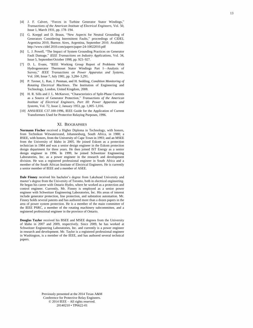
One type of directional element uses an impedance
calculation to determine direction. Elements using the
impedance method will see the system impedance during a
turn-to-turn fault. The negative-sequence directional element
is straightforward to set and does not need to coordinate with
other protection. The sensitivity of the element is a function of
the available operating current (I2) and polarizing voltage
(V2). Fig. 21 plots these values.
0 20 40 60 80 1000
0.15
0.3
0.45
0.6
0.75
0.9
1.05
1.2
1.35
1.5
Portion of the Winding That Is Shorted (%)
Ma
gn
itu
de
(p
u)
Negative-Sequence
CurrentNegative-Sequence
Voltage
Fig. 21. Negative-sequence current and voltage magnitude versus percent of
shorted winding for turn-to-turn faults.
Note that as the percentage of the shorted winding is
reduced, the resulting magnitudes of V2 and I2 are reduced.
For the modeled system, voltage will be the limiting factor.
Element coverage will depend on the minimum voltage
required by the element (often less than 1 V secondary) and
the instrument transformer accuracy. It is likely that the
scheme will be less effective for generators constructed of
multiple parallel branches per phase.
VII. CT SELECTION FOR DIFFERENTIAL PROTECTION
Effective differential protection requires adequate CT
performance. This section reviews the CT requirements for the
schemes described in Section V.
A. CT Ratio
Biased, high impedance, and negative-sequence differential
elements use the CTs on either side of the machine as inputs.
The polarizing input of the restricted earth fault scheme uses
the generator terminal CTs Because these CTs see the phase
currents, the ratio selection is a function of the maximum
expected current under normal operation of the machine.
Because the minimum current that is measurable by the relay
is a function of its nominal rating, choosing a higher ratio
translates to a lower sensitivity for these functions. Many
modern microprocessor-based relays can operate indefinitely
for currents of up to three times nominal. Typically, the
limiting factor will instead be governed by the rating factor of
the CT. The rating factor is the maximum current that can be
carried at a specified ambient temperature. Typical values are
1.0, 1.25, 1.33, 1.5, 2.0, 3.0, and 4.0. When the machine is at
full load, choose a ratio that results in a secondary current at
or near the CT nominal rating (1 or 5 A) and a rating factor
that allows for temporary overloading of the machine
( 1.5 pu).
B. CT Voltage Rating
Selecting a CT with a voltage rating greater than 1 + X/R
times the burden voltage for the maximum symmetrical fault
current ensures that the potential for a misoperation due to
saturation is not a concern. At the generator, the X/R ratio is
often very high and saturation may be unavoidable. In general,
a percent differential characteristic ensures that the phase
differential remains secure during an external fault with CT
saturation. Note that elements responding to sequence
components may not develop a significant restraint signal for
all fault types. These elements may make use of an external
fault detector or other mechanism to provide additional
security. Generally, CT performance is satisfactory if the CT
secondary maximum symmetrical external fault current
multiplied by the total secondary burden in ohms is less than
half of the voltage rating of the CT.
A misoperation for an external fault can result if one CT
enters saturation before the other. Therefore, CTs with
identical excitation characteristics should be applied on both
sides of the generator. It is usually not sufficient to match CTs
by voltage rating alone; it is also important to match the CT
secondary burden.
VIII. DIFFERENTIAL PROTECTION APPLICATION
RECOMMENDATIONS
When applying differential protection, the most crucial
factor to consider is the performance (characteristics) of the
CTs at the terminals and neutral of the machine. For optimal
12
sensitivity and security, all CTs in the differential zone should
be identical. The sensitivity of a differential scheme arises
from its operating principle—the summation of all of the
currents within the zone. Historically, the setting
considerations have been set to provide security during
external faults, especially when the CTs become saturated. As
was shown in Fig. 16 and Fig. 17, the differential element has
essentially two settings: minimum pickup and slope.
Element sensitivity is established by the differential relay
minimum pickup setting, which determines the smallest
current that the element can detect. This pickup value must be
set lower than the minimum fault current that can be generated
during a fault condition. If we examine Fig. 16, we see that the
minimum differential current for a phase-to-phase fault for
both the phase- and negative-sequence element was well
above the nominal current of the machine (1 pu). Therefore, a
pickup setting of 0.5 pu (half the full load current of the
machine) resulted in satisfactory performance of the element.
Setting the element any lower would not enhance the
sensitivity of the element but may reduce the security of the
element.
The slope setting of the differential element is determined
by calculating the maximum erroneous differential current
(operating current) that the differential element will measure
for a through-current event with no CT saturation. Defining ɛ
as the CT error and INeu and ITerm as the currents on either side
of the generator, the maximum erroneous differential current
(IOPERR) is as follows:
ERR Neu TermIOP 1 I 1 I (10)
Because INeu and ITerm are equal, we can express the
maximum error current in terms of the percentage of the
terminal current as follows:
ERRIOP 2 % (11)
For relaying CTs, the ANSI/IEEE C37.110 standard
defines a limit of 10 percent for the ratio error, at 20 times
rated secondary current at the standard burden [10]. This
equates to a maximum erroneous current of 20 percent of the
terminal current, so a slope setting of 25 percent would be in
order. This calculation applies for the case when the CTs have
identical characteristics and do not saturate. If this is not the
case, then the performance of the CTs under different external
fault conditions needs to be evaluated. For example, assume
that for an external fault or during the energization of the GSU
that the CT at the generator terminal saturates before the CT at
the neutral of the machine. A large erroneous differential
current will be computed by the differential element; the
following two options are available to the protection engineer:
Increase the slope setting to a value greater than the
error created by the erroneous differential current.
Employ a relay that has the ability to detect an
external fault. Secure the relay element during this
period, and return the relay to its normal operating
mode once the external fault has cleared.
The first option sacrifices the sensitivity of the element;
however, the second option maintains the sensitivity and
increases the security of the differential element. Because
generators not only have a large fault current but also a large
X/R ratio, the possibility of the CTs becoming saturated for an
external fault is very real. For this reason, selecting a relay
with the ability to detect an external fault and to secure the
relay during this time is advantageous.
Another issue that arises when the generator is used to
energize the GSU is that the GSU and the generator have a
very high X/R ratio. Even though the energization current may
be low, the energization current will contain a high dc
component. This will eventually drive the CTs into saturation
and cause the differential element to operate. It is advisable to
use a relay that has the ability to detect this condition and,
similar to the external fault condition, switch the relay into
high security mode.
IX. CONCLUSION
This paper describes the factors influencing the design of
the stator winding of a synchronous generator. We discuss the
construction of the individual components and describe in
detail the factors that lead to winding deterioration and failure.
This paper covers generator grounding practices and
applicable protection methods. We also present and compare
various differential protection methods.
Using an RTDS model, we simulate internal faults and
determine the response of various protection elements. The
results show that the phase, negative-, and zero-sequence
differential protection elements have the sensitivity to detect
all of the applied phase-to-phase faults. However, due to
limitations of the model, it was not possible to simulate faults
close to the generator neutral on both phases. Better models
are needed to assess protection coverage for this fault type.
The simulation results also show that differential elements
are effective in detecting ground faults. For this fault type, the
model allows faults to be applied at any point on the winding.
The results show that the relationship between fault position
and fault contribution is approximately linear for faults near
the generator neutral. This approximate linear relationship is
very useful for assessing protection sensitivity for ground
faults in general.
The RTDS simulation did not indicate that differential
elements were effective in detecting turn-to-turn faults;
however, other functions, such as impedance or directional
protection, can provide a degree of protection. Model
improvements, such as implementing parallel winding
branches, would allow a more comprehensive investigation of
this fault type.
X. REFERENCES
[1] M. G. Say, Alternating Current Machines, 5th ed. Pitman Publishing
Ltd., London, 1984.
[2] G. C. Stone, E. A. Boulter, I. Culbert, and H. Dhirani, Electrical
Insulation for Rotating Machines: Design, Evaluation, Aging, Testing,
and Repair. Wiley–IEEE Press, 2004.
[3] B. K. Gupta, B. A. Lloyd, G. C. Stone, S. R. Campbell, D. K. Sharma,
and N. E. Nilsson, “Turn Insulation Capability of Large AC Motors
Part 1—Surge Monitoring,” IEEE Transactions on Energy Conversion,
Vol. 2, Issue 4, December 1987, pp. 658–665.
13
[4] J. F. Calvert, “Forces in Turbine Generator Stator Windings,”
Transactions of the American Institute of Electrical Engineers, Vol. 50,
Issue 1, March 1931, pp. 178–194.
[5] G. Koeppl and D. Braun, “New Aspects for Neutral Grounding of
Generators Considering Intermittent Faults,” proceedings of CIDEL
Argentina 2010, Buenos Aires, Argentina, September 2010. Available:
http://www.cidel 2010.com/papers/paper-24-10022010.pdf
[6] L. J. Powell, “The Impact of System Grounding Practices on Generator
Fault Damage,” IEEE Transactions on Industry Applications, Vol. 34,
Issue 5, September/October 1998, pp. 923–927.
[7] D. L. Evans, “IEEE Working Group Report of Problems With
Hydrogenerator Thermoset Stator Windings Part I—Analysis of
Survey,” IEEE Transactions on Power Apparatus and Systems,
Vol. 100, Issue 7, July 1981, pp. 3,284–3,291.
[8] P. Tavner, L. Ran, J. Penman, and H. Sedding, Condition Monitoring of
Rotating Electrical Machines. The Institution of Engineering and
Technology, London, United Kingdom, 2008.
[9] H. R. Sills and J. L. McKeever, “Characteristics of Split-Phase Currents
as a Source of Generator Protection,” Transactions of the American
Institute of Electrical Engineers, Part III: Power Apparatus and
Systems, Vol. 72, Issue 2, January 1953, pp. 1,005–1,016.
[10] ANSI/IEEE C37.100-1996, IEEE Guide for the Application of Current
Transformers Used for Protective Relaying Purposes, 1996.
XI. BIOGRAPHIES
Normann Fischer received a Higher Diploma in Technology, with honors, from Technikon Witwatersrand, Johannesburg, South Africa, in 1988; a
BSEE, with honors, from the University of Cape Town in 1993; and an MSEE
from the University of Idaho in 2005. He joined Eskom as a protection technician in 1984 and was a senior design engineer in the Eskom protection
design department for three years. He then joined IST Energy as a senior
design engineer in 1996. In 1999, he joined Schweitzer Engineering Laboratories, Inc. as a power engineer in the research and development
division. He was a registered professional engineer in South Africa and a
member of the South African Institute of Electrical Engineers. He is currently a senior member of IEEE and a member of ASEE.
Dale Finney received his bachelor’s degree from Lakehead University and
master’s degree from the University of Toronto, both in electrical engineering. He began his career with Ontario Hydro, where he worked as a protection and
control engineer. Currently, Mr. Finney is employed as a senior power engineer with Schweitzer Engineering Laboratories, Inc. His areas of interest
include generator protection, line protection, and substation automation. Mr.
Finney holds several patents and has authored more than a dozen papers in the area of power system protection. He is a member of the main committee of
the IEEE PSRC, a member of the rotating machinery subcommittee, and a
registered professional engineer in the province of Ontario.
Douglas Taylor received his BSEE and MSEE degrees from the University
of Idaho in 2007 and 2009, respectively. Since 2009, he has worked at
Schweitzer Engineering Laboratories, Inc. and currently is a power engineer in research and development. Mr. Taylor is a registered professional engineer
in Washington, is a member of the IEEE, and has authored several technical
papers.
Previously presented at the 2014 Texas A&M
Conference for Protective Relay Engineers. © 2014 IEEE – All rights reserved.
20140210 • TP6622-01