Embed Size (px)
Citation preview

How to ensure you have a compliant PV installation ESV industry guidance June 2021

ESV Guidance: How to ensure you have a compliant PV installation June 2021
Contents Scope............................................................................................................................................... 1 Background ..................................................................................................................................... 1 Recommendations .......................................................................................................................... 2 ESV Connect ................................................................................................................................... 2 Summary ......................................................................................................................................... 3 Who we are ..................................................................................................................................... 3 Appendix 1: Recommended Earthing Method ................................................................................ 4 Appendix 2: Visual inspection ......................................................................................................... 6 Appendix 3: Testing – Continuity of the earthing system ............................................................... 7 Appendix 4: Testing - Insulation Resistance of PV cabling .......................................................... 11 Appendix 5: Testing – Polarity for PV d.c. cabling ........................................................................ 12
Scope The installation of a PV system is complex. There are a number of standards that are required to be followed and these standards have very detailed requirements for compliance. The objective of this guide is to assist Licensed Electrical Workers (LEWs) to ensure PV installations are installed and tested in accordance with the Electrical Safety Act 1998 and the relevant Australian Standards. In addition it is to provide access to information and recommendations to assist with compliance.
Relevant Regulations and Australian Standards • Electricity Safety Act 1998 • Electricity Safety (General) Regulations 2019 • AS/NZS 3000 Wiring Rules • AS/NZS 5033 Installation and safety requirements for photovoltaic (PV) arrays • AS/NZS 4777.1 Grid connection of energy systems via inverters – Installation requirement
It is recommended all workers consider OH&S processes and safety assessments to ensure the installation can be safely completed in accordance with WorkSafe Victoria regulations and requirements.
For more information, refer to the links below:
• ESV - Working safely when installing PV systems • Safe Work Australia - Safe Work of Roofs Information Sheet
Background As there are a large number of requirements in the standards and no two installations are the same, it is beneficial to utilise an installation checklist. By using a checklist it reminds you to check specific parts of the installation have been installed correctly and it also ensure the correct testing undertaken. AS/NZS 5033 requires the commissioning sheet and installation checklist to be provided to the customer.
Additionally data from the Solar Victoria Solar Homes program shows the most significant area of non-compliance is in regards to the correct earthing requirements of PV systems. This data is a possible

Energy Safe Victoria
ESV Guidance – Ensuring compliant earthing arrangements for PV Systems Page 2
indication that industry are not carrying out the earth continuity testing to a level that identifies un earthed PV arrays. It is LEWs obligation to ensure that all the mandated tests have been carried out and have passed. The LEI carries out identical tests as an independent verification process to ensure the system is safe to be placed into service. Both the LEW and LEI acknowledge that the test have been completed through signing the declaration on the CES, the information below is a simplified reminder for LEW’s on how to test PV installations and have this information readily available for future reference.
Recommendations 1. Ensure the PV system is earthed correctly.
See Appendix 1: Recommended Earthing Method for guidance on earthing.
2. On completion of the installation carry out the testing and verification requirements set out in AS/NZS 3000:2018 Section 8, Verification, and verify compliance to AS/NZS 5033
a. Utilise a detailed installation checklist to record testing and verification findings. See Note 1 and Note 2 below.
b. Carry out a visual inspection of the PV systems. See Appendix 2: Visual Inspection
3. Test the installation in line with the requirements of the standards. See Appendix 3: Testing – Continuity of the earthing system for guidance on testing of PV earthing system for PV systems See Appendix 4: Testing - Insulation Resistance of PV cabling for guidance on insulation testing for PV systems See Appendix 5: Testing – Polarity for PV d.c. cabling for guidance on polarity testing for PV systems
4. Provide the commissioning sheet and installation checklist to your electrical inspector. Commissioning sheets, installation checklists and other supporting documentation can be uploaded to ESV Connect. By providing this information to your inspector will assist in ensuring that the inspector has the appropriate information available and the inspection goes smoothly.
Note1: It is a mandatory requirement of AS/NZS 5033 (clause 5.7) to provide the commissioning sheet and installation checklist to the system owner.
Note 2: There are a number of checklists available throughout industry:
• The Clean Energy Installation Guidelines provides detailed installation and commissioning examples. There is also an online tool “My Jobs”
• Solar Victoria has released the PV Audit Checklist, which is detailed checklist of items checked during a Solar Vic audit.
• AS/NZS 5033:2014 Appendix D contains a sample commissioning sheet
ESV Connect Uploading your checklist and testing results to ESV connect will assist you by being able to provide evidence that the system was compliant at the end of the installation. Additionally it will assist the electrical inspector in being able to carry out the inspection in a timely manner as they will have detailed information on the system before attending site.
1. Create COES in ESV Connect as normal
2. Scroll down to the “Attachments” section of the online form
3. Click “+ Add Attachment”
Energy Safe Victoria
ESV Guidance – Ensuring compliant earthing arrangements for PV Systems Page 3
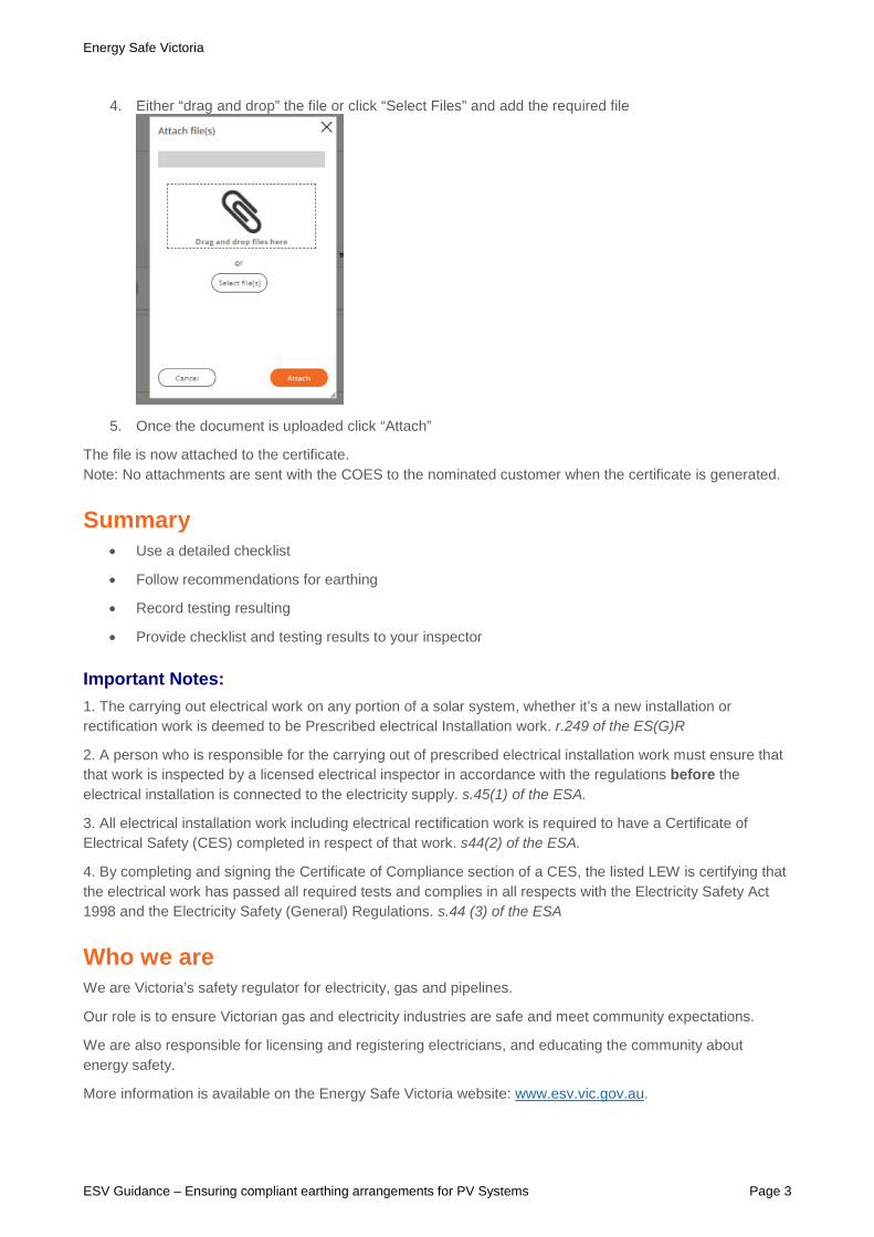
4. Either “drag and drop” the file or click “Select Files” and add the required file
5. Once the document is uploaded click “Attach”
The file is now attached to the certificate. Note: No attachments are sent with the COES to the nominated customer when the certificate is generated.
Summary • Use a detailed checklist
• Follow recommendations for earthing
• Record testing resulting
• Provide checklist and testing results to your inspector
Important Notes: 1. The carrying out electrical work on any portion of a solar system, whether it’s a new installation or rectification work is deemed to be Prescribed electrical Installation work. r.249 of the ES(G)R
2. A person who is responsible for the carrying out of prescribed electrical installation work must ensure that that work is inspected by a licensed electrical inspector in accordance with the regulations before the electrical installation is connected to the electricity supply. s.45(1) of the ESA.
3. All electrical installation work including electrical rectification work is required to have a Certificate of Electrical Safety (CES) completed in respect of that work. s44(2) of the ESA.
4. By completing and signing the Certificate of Compliance section of a CES, the listed LEW is certifying that the electrical work has passed all required tests and complies in all respects with the Electricity Safety Act 1998 and the Electricity Safety (General) Regulations. s.44 (3) of the ESA
Who we are We are Victoria’s safety regulator for electricity, gas and pipelines.
Our role is to ensure Victorian gas and electricity industries are safe and meet community expectations.
We are also responsible for licensing and registering electricians, and educating the community about energy safety.
More information is available on the Energy Safe Victoria website: www.esv.vic.gov.au.
Energy Safe Victoria
ESV Guidance – Ensuring compliant earthing arrangements for PV Systems Page 4
Appendix 1: Recommended Earthing Method Recent data from audits of solar installations have found that the number one defect for solar installations is inadequately earthed solar panels. There are two main methods used for earthing solar panels.
I. Parallel earthing where each panel is connected to the array earthing cable by a proprietary earthing lug.
II. Where the rails are connected to the array earthing cable and then the panels are connected to the rails by a proprietary bonding washer system.
The washer bonding system is the most common method used in Victoria and this recommendation is aimed at those systems. To ensure that solar panels are earth correctly and maintain the earthing connection when using the washer bonding system, ESV recommends the following:
1. Ensure that each solar panel mounting rail is connected to the array earthing cable.
Note: where earth cables spans from one rail to another it can be supported by installing a catenary or conduit between the rails or by using panel cable clips and clipping it to the edge of a panel.
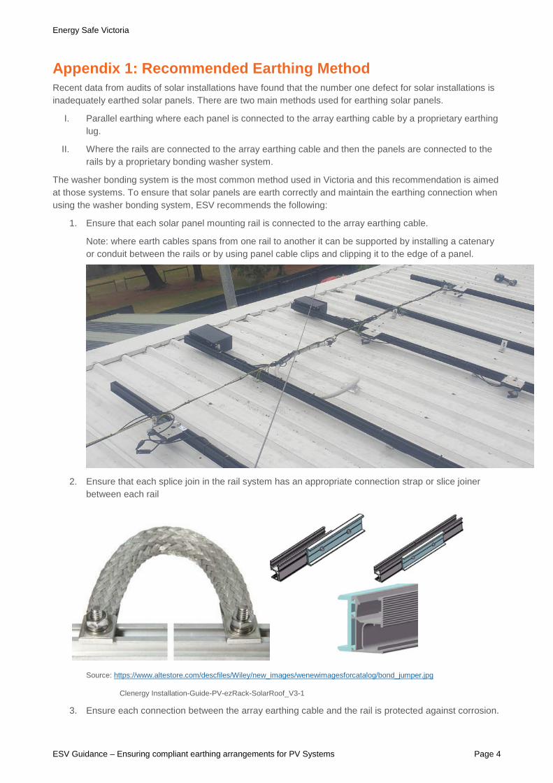
2. Ensure that each splice join in the rail system has an appropriate connection strap or slice joiner between each rail
Source: https://www.altestore.com/descfiles/Wiley/new_images/wenewimagesforcatalog/bond_jumper.jpg
Clenergy Installation-Guide-PV-ezRack-SolarRoof_V3-1
3. Ensure each connection between the array earthing cable and the rail is protected against corrosion.

Energy Safe Victoria
ESV Guidance – Ensuring compliant earthing arrangements for PV Systems Page 5
4. Ensure penetrating washers are installed correctly, with the penetrating washer dimples securely aligned and clamped between the PV module and the rail, or between the earth lug and the rail. A misaligned earth washer will compromise the array earthing integrity.
5. Ensure every clamp has a bonding washer installed.
A misaligned earthing washer may impede earth continuity. Ensure earth lug and PV Module earthing washers are correctly aligned and securely clamped between the two surfaces.
Energy Safe Victoria
ESV Guidance – Ensuring compliant earthing arrangements for PV Systems Page 6
Appendix 2: Visual inspection A Visual inspection of a solar installation should be carried out on a de-energised solar system, as in some unearthed situations, a voltage may be present on the exposed conductive parts of the solar installation creating a risk of electric shock.
It is recommended LEWs practise electrical safety protocols to ensure the solar system is safely isolated and locked out (i.e. using a LOTO kit).
Visual inspection requirements are outlined in Clause 8.2 of AS/NZS 3000. These requirements are more specifically written around a.c. systems. The draft version of AS/NZS 5033 (DR AS/NZS 5033:2021) outlined detailed PV specific visual inspection requirements in clause 4.7.2.
Below is additional detailed information regarding the visual inspection of PV system earthing.
Visual inspection – PV earthing system only Note: A visual inspection would normally be carried out in conjunction with the testing process.
A visual inspection of the PV installation earthing arrangement is to be conducted to verify the following:
1. The PV array earthing conductor is connected in a compliant manner in the same switchboard or distribution board to which the solar inverter is connected, or
2. The PV array earthing may be connected via the solar inverter. Where not subject to lightning, the inverter main earth conductor in the a.c. cable of the inverter output may be used as the earth connection point for the PV array, provided that the earthing is arranged such that the removal of the inverter for service will not interrupt the earth to the PV array. AS/NZS 5033:2014 Cl.4.4.2.2
3. The earthing conductor is of the correct type, colour and size. AS/NZS 3000:2018 Cl. 5.3.2
4. All earthing conductors and earthing mediums shall be installed in a manner that provides adequate protection against likely mechanical damage or deterioration. AS/NZS 3000:2018 Cl. 5.5.5
5. Earthing conductors shall be protected against becoming displaced, damaged or cut by being adequately supported by clips, clamps, saddles etc. and protected by a barrier/enclosure where appropriate to the expected conditions to prevent mechanical damage. AS/NZS 3000:2018 Cl. 5.5.5.2
6. Where conductors are exposed to direct sunlight, adequate installations methods must be adopted, refer to AS/NZS 3000:2018 Cl.3.3.2.11 Note 1. For insulated unsheathed (single insulated) cables with insulation colours other than black, the manufacturer’s recommendations should be sought, or the cable should be provided with a physical barrier to prevent exposure to direct sunlight.
7. Earthing or bonding connections to PV arrays shall be in accordance with AS/NZS 5033:2014 Cl. 4.4.2.2 (purpose-made fittings), each separate PV array shall be fitted with an earthing connection.
8. Earthing connections and any fixing devices shall be protected from corrosion AS/NZS 3000:2018 Cl. 5.5.5.3 (i.e.: painted with Cold Gal).
9. Joints in mounting rails shall be carried out as per the manufacturer’s instructions and manufacturer rail joiners if specified, to ensure continuity of the earthing arrangement throughout the PV array.
10. Penetrating washers layout shall be arranged and in accordance with the manufacturer’s instructions.
11. The earthing arrangement shall be arranged so that the removal of one or more PV modules will not affect the continuity of the earthing connections to any other PV module. AS/NZS 5033:2014 Cl. 4.4.2.2.

Energy Safe Victoria
ESV Guidance – Ensuring compliant earthing arrangements for PV Systems Page 7
Appendix 3: Testing – Continuity of the earthing system An effective earthing system will ensure exposed conductive parts of electrical equipment do not reach dangerous voltages when such faults occur.
The resistance of any equipotential bonding conductor or medium shall be not more than 0.5Ω.
Figure 1
Compliant earthing continuity Verification of the earthing system is a mandatory testing requirement of AS/NZS 3000, Section 8.
The following is a recommended testing process to verify compliant earthing continuity of a PV installation. (Refer to Fig. 1 above).
1. Check and confirm the earth conductors in the switchboard are correctly terminated and connections are compliant and tight. All connections throughout the solar installation shall be checked for compliance and tightness. (i.e.: ensure all conductor strands are captured, check for terminal tightness, and conduct a pull test on the conductor).
2. Identify and prove an earth reference point (ERP), this may be the main earth conductor or earth bar in the switchboard, the metal switchboard enclosure, the main earth electrode, metal water pipe, or nearby earth terminal of a socket outlet. Note: the ERP must be tested and verified to not more than 0.5 Ω when tested to the properties main earth conductor.
3. Connect a trailing earth lead and a continuity resistance tester together and zero the tester to accommodate the trailing earth lead resistance. (Refer to 3 in Fig.1)
TIP 1 Set yourself up with fittings for multiple test lead arrangement options, such as Banana plugs, Alligator clips, Battery clamps for water pipes, test probes for socket outlets etc.
Energy Safe Victoria
ESV Guidance – Ensuring compliant earthing arrangements for PV Systems Page 8
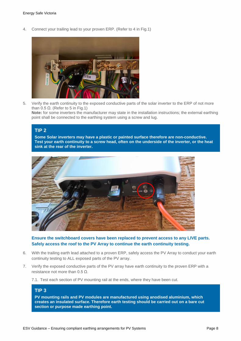
4. Connect your trailing lead to your proven ERP. (Refer to 4 in Fig.1)
5. Verify the earth continuity to the exposed conductive parts of the solar inverter to the ERP of not more
than 0.5 Ω. (Refer to 5 in Fig.1) Note: for some inverters the manufacturer may state in the installation instructions; the external earthing point shall be connected to the earthing system using a screw and lug.
Ensure the switchboard covers have been replaced to prevent access to any LIVE parts. Safely access the roof to the PV Array to continue the earth continuity testing.
6. With the trailing earth lead attached to a proven ERP, safely access the PV Array to conduct your earth continuity testing to ALL exposed parts of the PV array.
7. Verify the exposed conductive parts of the PV array have earth continuity to the proven ERP with a resistance not more than 0.5 Ω.
7.1. Test each section of PV mounting rail at the ends, where they have been cut.
TIP 2 Some Solar inverters may have a plastic or painted surface therefore are non-conductive. Test your earth continuity to a screw head, often on the underside of the inverter, or the heat sink at the rear of the inverter.
TIP 3 PV mounting rails and PV modules are manufactured using anodised aluminium, which creates an insulated surface. Therefore earth testing should be carried out on a bare cut section or purpose made earthing point.

Energy Safe Victoria
ESV Guidance – Ensuring compliant earthing arrangements for PV Systems Page 9
7.2. Test rails throughout the array, ensuring all rail joiners have achieved earth continuity.
7.3. Test each PV module at the corners where the two cut frames meet, or underneath the panel at the manufacturers earthing point.
Important Note: Aluminium oxidizes when exposed to air. Therefore PV Modules and rails commonly have a corrosion-resistant coating. This coating not only provides a protective barrier over the metal, but also resists an accurate earth test result. Any exposed edges or corners of the aluminium components will oxidize as they are exposed to the elements, this oxidisation on the bare edges may provide a level of resistance, therefore affecting the true earth test result.
Where an acceptable result cannot be achieved, test again by firmly pressing the tip of the test probe into the corner join. (Refer to photo above).
This will confirm either an adequate earth bond has been achieved, or prove that adequate earthing has not been achieved.
If an unacceptable earth result is obtained, the LEW must rectify the earthing arrangement to achieve a compliant earthing system for the installation.
With your Insulation Continuity Tester set on the 3Ω scale, verify the earth continuity is not more than0.5Ω.
Image above showing earthing points at the rear of a Hanwha Q Cells PV Module.

Energy Safe Victoria
ESV Guidance – Ensuring compliant earthing arrangements for PV Systems Page 10
Where accessible, you may also test the earth continuity to the manufacturer’s earthing point on the underside of the PV module, (Refer to on page 6).
TIP 4 An earth extension probe is handy to reach and test PV modules in difficult locations.

Energy Safe Victoria
ESV Guidance – Ensuring compliant earthing arrangements for PV Systems Page 11
Appendix 4: Testing - Insulation Resistance of PV cabling Appendix D4 of AS/NZS 5033 provides a detailed process of how to carry out this test. It is important that before a PV system is put into operation it is tested to ensure there is no leakage from the PV d.c. to earth.
1. ESV strongly recommends performing the following test before carrying out the whole test procedure outlined is Appendix D:
2. Follow the PV array disconnection steps (a) through to (d) in appendix D4, before continuing to step 3 of this test
3. Disconnect the last connection in the string of the string under test.
4. Ensure all d.c. isolators are in the on position
5. The insulation resistance test shall be carried out with an insulation test device using the 1000V d.c. test voltage connected between the PV array positive connection and the PV array negative connection. A minimum insulation resistance should not be less than 1MΩ.
Note: this test confirms that there is no leakage between positive and negative conductors of the PV array.
6. Once complete re-connect the last panel and continue with the rest of the testing outlined in Appendix D4 of AS/NZS 5033
.
Isolator Isolator
PCE
Energy Safe Victoria
ESV Guidance – Ensuring compliant earthing arrangements for PV Systems Page 12
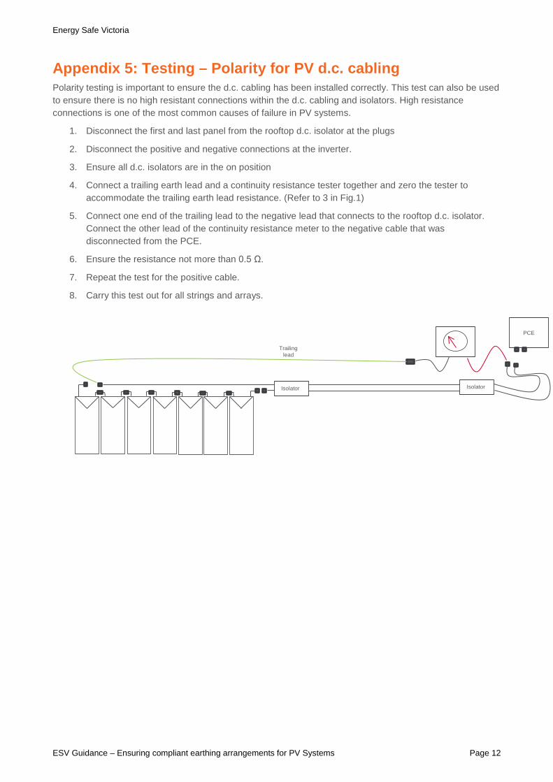
Appendix 5: Testing – Polarity for PV d.c. cabling Polarity testing is important to ensure the d.c. cabling has been installed correctly. This test can also be used to ensure there is no high resistant connections within the d.c. cabling and isolators. High resistance connections is one of the most common causes of failure in PV systems.
1. Disconnect the first and last panel from the rooftop d.c. isolator at the plugs
2. Disconnect the positive and negative connections at the inverter.
3. Ensure all d.c. isolators are in the on position
4. Connect a trailing earth lead and a continuity resistance tester together and zero the tester to accommodate the trailing earth lead resistance. (Refer to 3 in Fig.1)
5. Connect one end of the trailing lead to the negative lead that connects to the rooftop d.c. isolator. Connect the other lead of the continuity resistance meter to the negative cable that was disconnected from the PCE.
6. Ensure the resistance not more than 0.5 Ω.
7. Repeat the test for the positive cable.
8. Carry this test out for all strings and arrays.
Isolator Isolator
PCE
Trailing lead

![W3]IDOKRVV]DEENLHV«VH - Yellow Cube · 2017-09-13 · 73]ido 8'3 e\wh * esv 2 g esv * esv *esv *esv *esv *esv *esv *esv ,36 8'3 E\WH 0ESV * ESV 2 ,4 G ESV 3 *ESV 7 *ESV *ESV *ESV](https://img.pdfslide.net/doc/110x75/5f802c15a09b4f733d34aa37/w3idokrvvdeenlhvvh-yellow-cube-2017-09-13-73ido-83-ewh-esv-2-g-esv.jpg)