Embed Size (px)
Citation preview

(c) Fronius Australia Pty. Ltd, 01/2019 1/17
HOW TO INSTALL A FRONIUS SMART METER 63A-1 AND 63A-3 *for 63A-1, 63A-3 whole current Fronius Smart Meters only. For the 50kA Fronius Smart Meter and 240V/480V UL Fronius Smart Meters please refer to their respective guides.
Quick Guide
© Fronius Australia Pty Ltd.,
Version 3.0/2019
Fronius reserves all rights, in particular rights of reproduction, distribution and translation. No part of this work may be reproduced in any way without the written consent of Fronius. It must not be saved, edited, reproduced or distributed using any electrical or electronic system. You are hereby reminded that the information published in this document, despite exercising the greatest of care in its preparation, is subject to change and that neither the author nor Fronius can accept any legal liability Gender-specific wording refers equally to female and male form.

02/2017 2/17
1. GENERAL Fronius Smart Meters are energy meters which can be used to measure consumption data of a site, or for export limitation of a PV system with the Fronius SnapINverter range. The Fronius Smart Meter measures the power flow to the loads, or grid, and feeds the information via ModBus RTU/ RS485 communication to the Fronius Datamanager 2.0 (comes built-in with Fronius Galvo, Primo, Symo and Eco SnapINverters, excluding Light versions. It can also be retrofitted to all other Fronius inverters). This document describes how to install and set up only the 63A-1 single phase or 63A-3 3-phase Fronius Smart Meters. Please use the below links if using a different model of Fronius Smart Meter. Further information about the entire range of Fronius Smart Meters can be found in our Fronius Smart Meter Application Guide: https://www.fronius.com/~/downloads/Solar%20Energy/Whitepaper/SE_WP_Fronius_Smart_Meter_Application_Guide_EN_AU.pdf For installation and setup instructions of the 240V1-UL or 480V3-UL Fronius Smart Meters refer to the following document: https://www.fronius.com/~/downloads/Solar%20Energy/Operating%20Instructions/42%2C0410%2C2289.pdf For installation and setup instructions of the 50kA-3 Fronius Smart Meter refer to the following document: https://www.fronius.com/~/downloads/Solar%20Energy/Technical%20Articles/SE_TEA_Quick_Guide_How_to_install_and_commission_a_Fronius_Smart_Meter_50kA-3_EN_AU.pdf The document for setting export limitation with the Fronius Smart Meter can be found here: https://www.fronius.com/~/downloads/Solar%20Energy/Technical%20Articles/SE_TEA_Quick_Guide_How_to_set_up_Export_Limiting_using_the_Fronius_Smart_Meter_EN_AU.pdf

02/2017 3/17
1.1 Location of the Fronius Smart Meter
With the Fronius Smart Meter there are two possible energy paths/ locations where it can be installed. In almost all cases, the Fronius Smart Meter will be installed in the feed-in path. This is also the default setting in the Datamanager’s METER section. / Feed-in point In this position the Solar Supply Main Switch is on the load side of the Fronius Smart Meter / Consumption path In this position the Solar Supply Main Switch is on the grid side of the Fronius Smart Meter
Fronius
Utility meter
Fronius Smart Meter
Loads Loads
Fronius
Utility meter
Fronius Smart Meter
Loads Loads

02/2017 4/17
2. INSTALLING AND ACTIVATING A FRONIUS SMART METER
2.1 Schematics and wiring requirements
/ Wiring between Fronius Smart Meter and inverter should use a CAT5 or CAT6 cable. Important: To be compliant with the AS3000 standards, it is recommended to have the CAT5/CAT6 cable in a heat shrink tubing (probably 10mm) when it enters the switchboard part. Alternatively, use a 240V rated CAT5/CAT6 cable (e.g. Clipsal CBUS cable). Please note: Use a torque screw driver with a rating of 1.2 Nm – 1.4 Nm for the AC cable input terminals (Lin, Lout and Neutral) and a torque rating of 0.5 Nm – 0.8 Nm for the RS485 terminals. Any torque rating above the prescribed limits will damage the meter terminals and will not be covered under warranty. / Connection is a data line for Modbus RTU / RS485 using screw terminals on the meter. / Maximum distance: 300 m (980 feet) / Use a single core per terminal connection between Fronius Smart Meter and Datamanager 2.0. For D+ and D- use the single cores from the same colour (e.g. D+ is orange/white, D- is orange) Meter connection on the Datamanager 2.0 The meter needs to be connected to the Datamanager’s terminal block using terminals D+, D- and -.

02/2017 5/17
2.1.1 - Wiring detail for single-phase Fronius Smart Meter 63A/1PH & Datamanager 2.0
2.1.2 - Wiring detail for three-phase Fronius Smart Meter 63A/3PH and Datamanager 2.0
Modbus termination switch on the Datamanager The internal bus termination 120-Ohm resistance (for Modbus RTU) needs to be switched to ON. This switch is set to ON by default. Please Note: The termination resistance must be activated for the first and last device in an RS485 bus.

02/2017 6/17
2.2 Activating the Fronius Smart Meter
2.2.1 Activating the Fronius Smart Meter in the PV inverter homepage
The PV Inverter homepage can be accessed in two ways:
1. Via the Wi-Fi Access Point: - Activate the Wi-Fi Access Point on the Datamanager card (inverter screen under Setup) or
Datamanager Box 2.0 - Connect your computer/table/smart phone to the Fronius_240.XXXXXX network - Open a web browser and go to http://192.168.250.181. - Alternatively you can use the Fronius Solar.web App (Tablet/Smart Phone), open the Solar.web
app and select Settings. Then select “PV Inverter Homepage” or “Your System Monitoring” depending on your device.
2. Via the LAN Port:
- Connect your computer to the Datamanager via LAN cable - Switch the Datamanager IP Switch to Position ‘A’ - Open a web browser and go to http://169.254.0.180
Once connected follow the below steps:
It is recommended to complete the Solar.web Wizard first and get the system online. Once completed please go to Section 2.2.1 for the Fronius Smart Meter activation. If the system is not being set up for online monitoring, the Fronius Smart Meter can be activated within the Technician Wizard as per Section 2.2.2.
Step 1 Select Settings

02/2017 7/17
Step 3 Set a service password.
Minimum 8 characters with numbers and letters
Step 5 Select METER tab
111 Step 2
Select PASSWORDS
Step 4 Select the tick to save
the new password
Step 6 Login with Username: service and the password from Step 3
02/2017 8/17
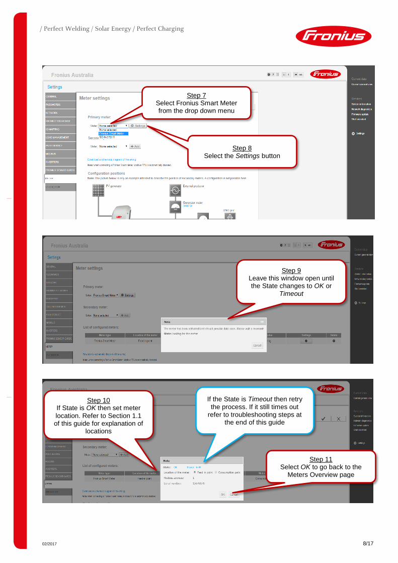
Step 7 Select Fronius Smart Meter from the drop down menu
Step 8 Select the Settings button
Step 9 Leave this window open until the State changes to OK or
Timeout
Step 10 If State is OK then set meter location. Refer to Section 1.1 of this guide for explanation of
locations
Step 11 Select OK to go back to the
Meters Overview page
If the State is Timeout then retry the process. If it still times out
refer to troubleshooting steps at the end of this guide

02/2017 9/17
2.2.2 Activating the Fronius Smart Meter in the Technician Wizard The Technician Wizard can be accessed in two ways:
1. Via the Wi-Fi Access Point: - Activate the Wi-Fi Access Point on the Datamanager card (inverter screen under Setup) or
Datamanager Box 2.0 - Connect your computer/table/smart phone to the Fronius_240.XXXXXX network - Open a web browser and go to http://192.168.250.181. - Alternatively you can use the Fronius SolarWeb App (Tablet/Smart Phone), open the Solar.web app
and select Settings. Then select PV Inverter Homepage or Your System Monitoring depending on your device.
2. Via the LAN Port:
- Connect your computer to the Datamanager via LAN cable - Switch the Datamanager IP Switch to Position ‘A’ - Open a web browser and go to http://169.254.0.180
Once connected follow the below steps:
Step 12 Select the tick to save the
Meter Settings
Older software versions do not have the List of Configured Meters or Secondary Meter
Step 13 Select Current General View to
go to real-time data
Step 14 Site Consumption and grid
export/import should now be shown

02/2017 10/17
Step 1 Select Technician Wizard to begin
Step 2 Set System Name, Yield
and Date/Time then select Forward

02/2017 11/17
Step 3 Set the DC array Watt Peak (Wp) value for all inverters
then select Forward
Step 4 Set a service password to limit
access. Minimum 8 characters with both numbers and letters. Then
select Forward
Important: Make a note of the service password as it’s
required to make any changes to the smart meter
settings later on

02/2017 12/17
Step 5 Login with username: service and the password created in Step 4
Step 6 Skip Forward over IO Mapping

02/2017 13/17
Step 7 Select Fronius Smart Meter from the dropdown box and
then select Settings
Older software versions do not have the List of Configured Meters or Secondary Meter
Step 8 Leave this window open until the State changes to OK or
Timeout

02/2017 14/17
Step 9 If State is OK then set meter location and select OK. Refer to Section 1.1 of this guide for
explanation of locations
Step 10 Select Forward
Older software versions do not have the List of Configured Meters or Secondary Meter
If the State is Timeout then retry the process. If it still times-out
refer to troubleshooting steps in Section 4 of this guide

02/2017 15/17
Step 11 Select Forward
If an export limit needs to be set, please refer to our
separate export limiting guide.
The Technician Wizard is now complete and the meter has been
setup. Online monitoring can be setup via the Solar.Web Wizard

02/2017 16/17
3. ACTIVATING NIGHT MODE* ON THE INVERTER DISPLAY Night mode is required to be activated to log site consumption values overnight. To activate night mode complete the below steps on the inverter display:
1) Enter the Setup menu 2) Scroll down and enter Display Settings
3) Scroll down and enter Night Mode 4) Set to ON and enter to save the setting
*Night mode: Not applicable on Fronius Symo Hybrid inverters.

02/2017 17/17
4. FRONIUS SMART METER TROUBLESHOOTING
4.1 – Timeout: meter not detected If the Fronius Smart Meter is not being detected in the Technician wizard or PV Inverter homepage try the following steps in order. After each step try to activate the meter again.
1) Restart the Datamanager. Shutdown both AC and DC to the inverter to switch it off, and then power it back up. Reconnect to the Wi-Fi access point and attempt to activate the meter again.
2) Switch the position of the Master – Slave switch on the Datamanager Card from Master to Slave. Wait for 10 seconds and then switch it back to Master and then try activating the meter again. Please note: If this step is being followed, make sure that the W-Fi access point on the inverter is active and then your device should be connected to the Wi-Fi access point.
3) Check that the 120Ω resistor is installed correctly across the meter terminals as per the wiring diagrams in Section 2.1.
4) Confirm that the cable used between meter terminals and Datamanager 2.0 terminal block are properly terminated.
5) Confirm that the RS485 wiring between meter terminals and Datamanager 2.0 terminal block are correct as per the wiring diagrams in Section 2.2.
6) If cable is short enough, complete a continuity test on the cores used to ensure no breaks in the cable.
7) Update the Datamanager 2.0 software. After software update restart the Datamanager 2.0 as per Step 1 of this section. Refer to our update guide for more information: https://www.fronius.com/~/downloads/Solar%20Energy/Technical%20Articles/SE_TEA_Quick_guide_How_to_update_Fronius_Datamanager_firmware_EN_AU.pdf
4.2 – Data is not accurate in Solar.web
1) Meter is set in the incorrect path compared to actual installation: Refer to Section 1.1 of this guide and correct as per the above set-up steps in 2.2.1 and 2.2.2.
2) Meter is installed in the wrong location in the switchboard: It must be installed after the Normal Supply Main switch and before the rest of the site loads including the Solar Supply Main Switch for feed in path. Refer to the single line diagrams in Section 1.1
3) If getting minimal load consumption values the meter may be in parallel with the Normal Supply Main Switch. Ensure they are in series or the meter will be mostly bypassed.
4.3 – Night consumption values are not logged in Solar.web
1) Turn on night mode as per Section 3 of this guide