Embed Size (px)
Citation preview

A000
aHow this section page is organised aGraph of chip control by work material zOrganised according to turning insert shape. (Refer to the index on the next page.) xInserts are arranged in order of : ·Negative inserts (with hole|without hole) ·Positive inserts (with hole|without hole) cBreakers are arranged in order of : Finish Cutting|Light Cutting|Medium Cutting |Semi-Heavy Cutting|Heavy Cutting
Shows recommended chip breakers and chip control range according to work material and cutting application.Graphs are coloured according to cutting applications(Finish|Light|Medium|Semi-Heavy|Heavy)and contain recommended breakers for each application.
INSERT NUMBER
PAGE REFERENCE ·CHIP BREAKERS ·GRADES ·TECHNICAL DATA indicates reference pages, on the right hand page of each double-page spread.
INSERT GRADES
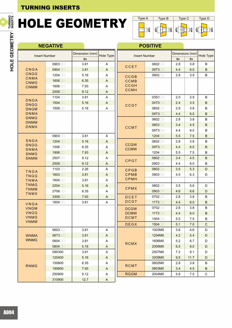
FIGURE SHOWING THE INSERT GEOMETRY D1 : Diameter of Inscribed Circle S1 : Thickness Re : Corner Radius & D2 : Diameter of Hole Dimensions are detailed in the "Dimensions" column.
APPLICABLE HOLDER PAGE indicates reference pages for details of applicable holders.
aTo Order : Please specifyzinsert number and xgrade.
TITLE OF PRODUCT ACCORDING TO THE INSERT TYPE PRODUCT SECTION
GRADE APPLICATION RECOMMENDED FOR EACH WORK MATERIAL cutting conditions suitable for each type of work material is shown as a general guide to select the grade.
LEGEND FOR STOCK STATUS MARKis shown on the left hand page of each double-page spread.CUTTING APPLICATIONis shown in order of: Finish�Light�Medium�Semi-Heavy�Heavy.PHOTO OF INSERTINDICATION OF CHIPBREAKERindicates the designation for a chipbreaker.
INDICATION OF NEGATIVE/POSITIVE TYPE SHAPE & ANGLE MARK
STOCK STATUS
INSERT DIMENSIONS
Finish Cutting :
HOW TO READ THE STANDARD OF TURNING INSERTS
Semi-Heavy Cutting : Light Cutting : Medium Cutting :
Heavy Cutting :
: Stable Cutting : General Cutting : Unstable Cutting

A001
A002A004A006A009A010A015A016A018A019A020A022A024A025A026A027A028
A048A053A057A058A062A068A070
A073A074A075
A076A078A079A084A088A089
A090A091A092A093A094A095A098A099A100A101A102A103
A104A106A108
INSERT GRADESINSERT STANDARDS
INDENTIFICATION ...............................................................HOLE GEOMETRY ...............................................................PRECISION BREAKER SYSTEM ........................................OUTLINE OF ...............................................MITSUBISHI CARBIDE BREAKER SYSTEM......................PRECISION BREAKER SYSTEM ........................................WIPER INSERT.....................................................................GRADES FOR TURNING .....................................................TURNING APPLICATION RANGE .......................................COATED CARBIDE (CVD) ...................................................COATED CARBIDE (PVD) ...................................................CERMET ...............................................................................COATED CERMET ...............................................................CEMENTED CARBIDE.........................................................MICRO-GRAIN CEMENTED CARBIDE ...............................CLASSIFICATION OF INSERTS..........................................
NEGATIVE INSERTS WITH HOLE CNooTYPE...RHOMBIC 80°............ DNooTYPE...RHOMBIC 55°............
RNooTYPE...ROUND ................... SNooTYPE...SQUARE 90° ............. TNooTYPE...TRIANGULAR 60° ....... VNooTYPE...RHOMBIC 35° ............
WNooTYPE...TRIGON 80° ..............NEGATIVE INSERTS WITHOUT HOLE SNooTYPE...SQUARE 90° ............. TNooTYPE...TRIANGULAR 60° ....... KNooTYPE...PARALLELOGRAM 55° ...POSITIVE INSERTS WITH HOLE VBooTYPE...RHOMBIC 35° ............
WBooTYPE...TRIGON80°............... CCooTYPE...RHOMBIC 80°............ DCooTYPE...RHOMBIC 55°............ RCooTYPE...ROUND ................... SCooTYPE...SQUARE 90° .............
TCooTYPE...TRIANGULAR 60° ....... VCooTYPE...RHOMBIC 35° ............ WCooTYPE...TRIGON 80° .............. CPooTYPE...RHOMBIC 80°............ SPooTYPE...SQUARE 90° ............. TPooTYPE...TRIANGULAR 60°........
WPooTYPE...TRIGON 80° .............. VDooTYPE...RHOMBIC 35° ............ DEooTYPE...RHOMBIC 55° ............ TEooTYPE...TRIANGULAR 60°........ RDooTYPE...ROUND ................... RGooTYPE...ROUND ...................POSITIVE INSERTS WITHOUT HOLE SPooTYPE...SQUARE 90° ............. TPooTYPE...TRIANGULAR 60°........ RTG TYPE..................................
TURNING
STANDARD OF INSERTS

A002
H
O
P
S
T
C
D
E
F
M
V
W
L
A
B
K
R
e0.005e0.005e0.013e0.013e0.025e0.025e0.005e0.013e0.025
e0.08�e0.18e0.08�e0.18e0.13�e0.38
AFCHEGJKLMNU
e0.025e0.013e0.025e0.013e0.025e0.025
e0.05�e0.15e0.05�e0.15e0.05�e0.15e0.05�e0.15e0.05�e0.15e0.08�e0.25
e0.025e0.025e0.025e0.025e0.025e0.13e0.025e0.025e0.025e0.13e0.025e0.13
e0.08e0.08e0.13e0.15e0.15
��
e0.08e0.08e0.13e0.15e0.15
��
e0.11e0.11e0.15e0.18e0.18
��
e0.16e0.16
�����
e0.08e0.08e0.13e0.15e0.15e0.18e0.20
6.35 9.52512.7015.87519.0525.4031.75
e0.05e0.05e0.08e0.10e0.10
��
e0.05e0.05e0.08e0.10e0.10
��
e0.05e0.05e0.08e0.10e0.10
��
e0.05e0.05
�����
e0.05e0.05e0.08e0.10e0.10e0.13e0.15
6.35 9.52512.7015.87519.0525.4031.75
C N M G
A 3°
B 5°
C 7°
D 15°
E 20°
F 25°
G 30°
N 0°
P 11°
O
W
T
Q
U
B
H
C
J
A
M
G
N
R
F
X
z c
x v
�������
�e0.05e0.08e0.10e0.10e0.13e0.15
(40 �60°)
(40 �60°)
(70 �90°)
(70 �90°)
m
øD1øD1
m
m
S1
IDENTIFICATION TURNING INSERTS
Triangular insert with a facet (Secondary Cutting Edge)Symbol
Hexagonal
Octagonal
Pentagonal
Square
Triangular
Rhombic80°
Rhombic55°
Rhombic75°
Rhombic50°
Rhombic86°
Rhombic35°
Trigon
Rectangular
Parallelogram85°
Parallelogram82°
Parallelogram55°
Round
Insert Shape
Symbol
The surface of insert with * mark is sintered.
Tolerance of Nose Height
m (mm)
Tolerance ofInscribed Circle
øD1 (mm)
Tolerance of ThicknessS1 (mm)
D.I.C. Triangular Square Rhombic80°
Rhombic55°
Rhombic35°
Square Rhombic80°
Rhombic55°
Rhombic35°
Round
D.I.C. Triangular RoundD.I.C.
Detail of M Class Insert Tolerance aTolerance of Nose Height (mm)
aTolerance of Inscribed Circle (mm)
Symbol
Symbol HoleHole
ConfigurationChip
BreakerChip
BreakerFigure Symbol HoleHole
Configuration Figure
With Hole
With Hole
With Hole
With Hole
With Hole
With Hole
With Hole
With Hole
With Hole
With Hole
With Hole
WithoutHole
WithoutHole
WithoutHole
� � Special Design
Cylindrical Hole
Cylindrical Hole
Cylindrical Hole
�
�
�
�
Cylindrical Hole +
One Countersink
Cylindrical Hole +
Double Countersink
Cylindrical Hole +
One Countersink
Cylindrical Hole +
Double Countersink
DoubleSided
DoubleSided
No
No
No
No
OneSided
DoubleSided
DoubleSided
No
No
OneSided
OneSided
OneSided
Other Normal Clearance
Major Normal Clearance
Normal Clearance Metric
z Symbol for Insert Shape
c Symbol for Tolerance Class
x Symbol for Normal Clearance v Symbol for Fixing and/or for Chip Breaker
c Symbol for Tolerance Class
*****
IDEN
TIFI
CAT
ION
TUR
NIN
GIN
SER
TS

A003
L302
030809
040506
030405
030405
06
S1
01
T0
02
T2
03
T3
04
06
07
09
1.39
1.59
1.79
2.38
2.78
3.18
3.97
4.76
6.35
7.94
9.52
00V3V501020408121620242832
0.03
0.05
0.1
0.2
0.4
0.8
1.2
1.6
2.0
2.4
2.8
3.2
0809
0604 11
1307 06 06 11 09 08 07 13 05
0809 06 16 11 09 09 16 101212 08 22 15 12 12 22
19 16 15 27
23 19 19 33
27 22 22 38
31 25 25 44 38 32 31 54
10161920
25253132
13
3.97
4.76
5.56
6.00
6.35
7.94
8.00
9.525
10.00
12.00
12.70
15.875
16.00
19.05
20.00
22.225
25.00
25.40
31.75
32.00
12 04 08 (E) (N) MV-
F
E
T
S
R
L
N
FJFH
FS FV
GJGH
FY
HX
HL
HM HV
MA MJ
MS MV MW
SH
MH
SA SW
b n /
m , .
Sharp Nose Sharp
Cutting Edges
RoundCutting Edges
ChamferedCutting Edges
Chamferedand Rounded Cutting Edges
Symbol
Symbol Figure Cutting Edge Symbol Figure
Standard
Hand SymbolCorner Radius (mm)
Symbol Thickness (mm)
Diameter of Inscribed Circle
(mm)
b Symbol for Insert Size
m Symbol for Insert Corner Configuration , Symbol for Cutting Edge Condition . Symbol for Cutting Direction
n Symbol for Insert Thickness
/ Symbol for Chip Breaker
Round Insert
Mitsubishi Materials omitthe honing symbol.
(Refer to JIS-B4120-1998)
Right
Left
Neutral
*Thickness is from the bottom of the insert to the top of the cutting edge.
IDEN
TIFI
CAT
ION
InchMetric
00 : M0 :
TUR
NIN
GIN
SER
TS
A004
C N G ACNGGC N M ACNMGCNMM
D N G ADNGGDNGMD N M ADNMGDNMMDNMX
S N G ASNGGS N M ASNMGSNMM
T N G AT N G GT N M ATNMGTNMMT N M X
V N G AVNGMVNGGVNMGVNMM
WNMAWNMG
RNMG
3.81
3.81
5.16
6.35
7.93
9.12
3.81
5.16
5.16
3.81
5.16
6.35
7.93
9.12
9.12
2.26
3.81
3.81
5.16
6.35
7.93
3.81
3.81
3.81
3.81
5.16
3.81
5.16
6.35
7.93
9.12
12.7
A
A
A
A
A
A
A
A
A
A
A
A
A
A
A
A
A
A
A
A
A
A
A
A
A
A
A
A
A
A
A
A
0903pp
0904pp
1204pp
1606pp
1906pp
2509pp
1104pp
1504pp
1506pp
0903pp
1204pp
1506pp
1906pp
2507pp
2509pp
1103pp
1603pp
1604pp
2204pp
2706pp
3309pp
1604pp
0603pp
06T3pp
0604pp
0804pp
090300
120400
150600
190600
250900
310900
D2
C C E T
C C G T
C C M T
C C G BCCMBCCGHCCMH
CCGWCCMW
C P G T
C P M X
D E G X
C P G BC P M BCPMH
D C E TD C G T
DCGWDCMWD C M T
RCMX
R C M T
RGGM
2.8
4.4
2.8
2.0
2.4
2.8
4.4
2.8
3.4
4.4
5.5
2.8
4.4
5.5
3.4
4.4
3.5
4.5
3.5
4.6
2.8
4.4
2.8
4.4
5.5
5.1
3.6
4.2
5.2
6.5
7.2
9.5
2.8
3.4
5.6
B
B
B
B
B
B
B
B
B
B
B
B
B
B
B
B
D
D
D
D
B
B
B
B
B
C
D
D
D
D
D
D
B
B
C
0602pp
09T3pp
0602pp
03S1pp
04T0pp
0602pp
09T3pp
0602pp
0803pp
09T3pp
1204pp
0602pp
09T3pp
1204pp
0802pp
0903pp
0802pp
0903pp
0802pp
0903pp
0702pp
11T3pp
0702pp
11T3pp
1504pp
1504pp
1003M0
1204M0
1606M0
2006M0
2507M0
3209M0
0602M0
0803M0
2004M0
D2
3.8
6.0
3.9
2.9
3.5
3.8
6.0
3.8
4.5
6.0
7.5
3.8
6.0
7.5
4.5
6.0
5.3
6.3
5.6
6.6
3.8
6.0
3.8
6.0
7.5
7.0
4.6
5.4
6.7
8.0
9.1
11.7
3.8
4.5
7.5
D3
øD3
øD2
øD3
øD2
øD3
øD2
øD2
NEGATIVE
HOLE GEOMETRY TURNING INSERTS
Insert Number Dimension (mm)Hole Type
POSITIVE
Insert Number Dimensions (mm)Hole Type
Type DType CType BType A
HO
LE G
EOM
ETR
YTU
RN
ING
INSE
RTS

A005
WBGTWBMT
WPGTWPMT
WCGTWCMTWCMW
2.3
2.3
2.3
2.3
2.8
4.4
2.8
4.4
B
B
B
B
B
B
B
B
0201pp
L302pp
0201pp
L302pp
0402pp
06T3pp
0402pp
0603pp
D2
3.2
3.2
3.0
3.0
3.8
6.0
3.8
6.0
D3
S C M TSCMW
T C G TT C M TTCGWTCMW
SPMW
S P M T
S P G X
T E G X
T P G X
T P M X
T P G V
T P G T
V C G TV C M TVCGWVCMW
T P G BT P M BT P G HT P M H
V B E TV B G TV B M TVBGW
V D G X
4.4
5.5
4.6
5.7
4.4
5.5
4.8
5.9
2.3
2.3
2.5
2.8
3.4
4.4
4.4
2.5
3.0
3.5
4.8
2.7
3.2
3.7
4.8
2.4
2.9
3.4
4.4
2.8
3.4
4.4
2.9
4.4
2.4
2.8
4.4
4.5
B
B
B
B
B
B
D
D
B
B
B
B
B
B
D
C
C
C
D
C
C
C
D
D
D
D
D
B
B
B
B
B
B
B
B
D
09T3pp
1204pp
0903pp
1203pp
0903pp
1203pp
0903pp
1203pp
0601pp
0802pp
0902pp
1102pp
1303pp
16T3pp
1603pp
0802pp
0902pp
1103pp
1603pp
0802pp
0902pp
1103pp
1603pp
0802pp
0902pp
1103pp
1603pp
0902pp
1103pp
1603pp
1103pp
1604pp
0802pp
1103pp
1604pp
1603pp
D2
6.0
7.5
6.0
7.5
6.0
7.5
6.4
7.7
3.2
3.0
3.3
3.8
4.5
6.0
6.1
3.8
4.3
4.8
6.4
3.8
4.3
4.8
6.4
4.0
4.3
4.8
6.5
3.8
4.5
6.0
3.8
6.0
3.2
3.8
6.0
6.1
D3
øD3
øD2
øD3
øD2
øD3
øD2
øD2
POSITIVE
Insert Number Dimensions (mm)Hole Type Insert Number Dimensions (mm)
Hole Type
HO
LE G
EOM
ETR
YTU
RN
ING
INSE
RTSType DType CType BType A

A006
L3 L4 B2 B7
DNGG150404R/L150408R/L
2.8
2.8
�
�
15
15�
�
1.8
1.8
2.3
2.3
1.6
1.6
3.7
3.7
15
15
15
15
�
�
�
�
SNGG090304R/L090308R/L120404R/L120408R/L
TNGG160402R/L-F160404R/L-F160408R/L-F
2.5
2.5
2.5
�
�
�
15
15
15
30
30
30
TNGG110302R/L110304R/L110308R/L160304R/L160308R/L160402R/L160404R/L160408R/L160412R/L220404R/L220408R/L220412R/L
1.3
1.3
1.3
2.3
2.3
1.3
2.3
2.3
2.3
2.8
2.8
2.8
3.2
3.0
2.7
5.4
5.1
8.7
5.4
5.1
4.8
9.4
9.1
8.8
15
15
15
15
15
15
15
15
15
15
15
15
�
�
�
�
�
�
�
�
�
�
�
�
VNGG160404R/L160408R
1.8
1.8
�
�
15
15�
�
a
L3 B2
L3
L4
B2
L3
L3B2 B7
L4
L3 B2
L3 B2
TURNING INSERTS
STANDARD OF INSERTS WITH HAND OF TOOL NEGATIVE INSERTS
Geometry Insert Number
Right hand insert shown.
Right hand insert shown.
Right hand insert shown.
Right hand insert shown.
Right hand insert shown.
PREC
ISIO
N B
REA
KER
SYS
TEM
PRECISION BREAKER SYSTEMTUR
NIN
GIN
SER
TS
A007
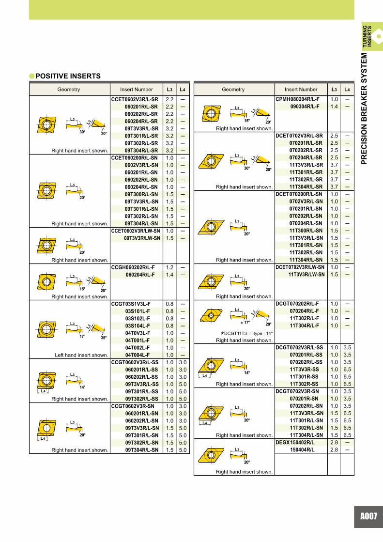
CCET 0602V3R/L-SR 060201R/L-SR 060202R/L-SR 060204R/L-SR 09T3V3R/L-SR 09T301R/L-SR 09T302R/L-SR 09T304R/L-SR CCET 060200R/L-SN 0602V3R/L-SN 060201R/L-SN 060202R/L-SN 060204R/L-SN 09T300R/L-SN 09T3V3R/L-SN 09T301R/L-SN 09T302R/L-SN 09T304R/L-SN CCET 0602V3R/LW-SN 09T3V3R/LW-SN
CCGH 060202R/L-F 060204R/L-F
CCGT 03S1V3L-F 03S101L-F 03S102L-F 03S104L-F 04T0V3L-F 04T001L-F 04T002L-F 04T004L-F CCGT 0602V3R/L-SS 060201R/L-SS 060202R/L-SS 09T3V3R/L-SS 09T301R/L-SS 09T302R/L-SS CCGT 0602V3R-SN 060201R/L-SN 060202R/L-SN 09T3V3R/L-SN 09T301R/L-SN 09T302R/L-SN 09T304R/L-SN
2.22.22.22.23.23.23.23.21.01.01.01.01.01.51.51.51.51.51.01.5
1.21.4
0.80.80.80.81.01.01.01.01.01.01.01.01.01.01.01.01.01.51.51.51.5
��������������������
��
��������
3.03.03.05.05.05.03.03.03.05.05.05.05.0
CPMH 080204R/L-F 090304R/L-F
DCET 0702V3R/L-SR 070201R/L-SR 070202R/L-SR 070204R/L-SR 11T3V3R/L-SR 11T301R/L-SR 11T302R/L-SR 11T304R/L-SR DCET 070200R/L-SN 0702V3R/L-SN 070201R/L-SN 070202R/L-SN 070204R/L-SN 11T300R/L-SN 11T3V3R/L-SN 11T301R/L-SN 11T302R/L-SN 11T304R/L-SNDCET 0702V3R/LW-SN 11T3V3R/LW-SN
DCGT 070202R/L-F 070204R/L-F 11T302R/L-F 11T304R/L-F
DCGT 0702V3R/L-SS 070201R/L-SS 070202R/L-SS 11T3V3R-SS 11T301R-SS 11T302R-SSDCGT 0702V3R-SN 070201R-SN 070202R/L-SN 11T3V3R/L-SN 11T301R/L-SN 11T302R/L-SN 11T304R/L-SNDEGX 150402R/L 150404R/L
1.01.4
2.52.52.52.53.73.73.73.71.01.01.01.01.01.51.51.51.51.51.01.5
1.01.01.01.0
1.01.01.01.01.01.01.01.01.01.51.51.51.52.82.8
��
��
��
����
3.53.53.56.56.56.53.53.53.56.56.56.56.5
������������������
L3 L4 L3 L4
a
L3
30°
15°
20°
20°
15°
L3
20°
L3
35°
L3
20°
L4
L4
L3
20°
L3
20°
L3
20°
L4
L4
17°
14°
20°
30°
20°
20°
17°
14°
20°
20°
L3
L3
L3
L3
L3
L3
L3
L3
L3
L3
L3
L3
L3
L3
Geometry Insert Number Geometry Insert Number
POSITIVE INSERTS
Right hand insert shown.
Right hand insert shown.
Right hand insert shown.
Right hand insert shown.
Right hand insert shown.
Right hand insert shown.
Right hand insert shown.
Right hand insert shown.
Right hand insert shown.
Right hand insert shown.
Right hand insert shown.
Left hand insert shown.
Right hand insert shown.
Right hand insert shown.
*DCGT11T3pptype : 14°Right hand insert shown.
*
PREC
ISIO
N B
REA
KER
SYS
TEM
TUR
NIN
GIN
SER
TS
A008
L3 L4 L3 L4
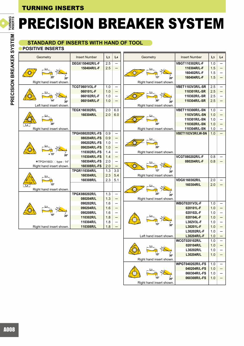
DEGX 150402R/L-F 150404R/L-F
TCGT 0601V3L-F 060101L-F 060102R/L-F 060104R/L-F
TEGX 160302R/L 160304R/L
TPGH 080202R/L-FS 080204R/L-FS 090202R/L-FS 090204R/L-FS 110302R/L-FS 110304R/L-FS 160304R/L-FS 160308R/L-FSTPGR 110304R/L 160304R/L 160308R/L
TPGX 080202R/L 080204R/L 090202R/L 090204R/L 090208R/L 110302R/L 110304R/L 110308R/L
VBGT 110302R/L-F 110304R/L-F 160402R/L-F 160404R/L-F
VBET 1103V3R/L-SR 110301R/L-SR 110302R/L-SR 110304R/L-SR
VBET 110300R/L-SN 1103V3R/L-SN 110301R/L-SN 110302R/L-SN 110304R/L-SNVBET1103V3R/LW-SN
VCGT 080202R/L-F 080204R/L-F
VDGX 160302R/L 160304R/L
WBGT 0201V3L-F 020101L-F 020102L-F 020104L-F L302V3L-F L30201L-F L30202R/L-F L30204R/L-F WCGT 020102R/L 020104R/L L30202R/L L30204R/L
WPGT 040202R/L-FS 040204R/L-FS 060304R/L-FS 060308R/L-FS
2.52.5
1.01.01.01.0
2.02.0
0.90.91.01.01.41.42.02.01.32.32.3
1.31.31.61.61.61.81.81.8
��
����
��������
��������
6.06.0
3.05.45.1
1.01.51.51.5
2.52.52.52.5
1.01.01.01.01.01.0
0.80.8
2.02.0
1.01.01.01.01.01.01.01.01.01.01.01.0
1.01.01.01.0
����
����
������
��
��
������������
����
a
L3
20°
L3
20°
L4
L4
L3
20°
L3
20°
L3
20°
L3
20°
L3
30°
L3
20°
L3
30°
L3
20°25°
14°
20°
15°
15°
L3
20°10°
13°
30°
20°
20°
13°
25°
13°
15°
15°
L3
L3
L3
L3
L3
L3
L3
L3
L3
L3
L3
L3
L3
L3
L3
TURNING INSERTS
STANDARD OF INSERTS WITH HAND OF TOOL POSITIVE INSERTS
Right hand insert shown.
Left hand insert shown.
Right hand insert shown.
Right hand insert shown.
Right hand insert shown.
Right hand insert shown.
Right hand insert shown.
Left hand insert shown.
Right hand insert shown.
Right hand insert shown.
Right hand insert shown.
Right hand insert shown.
Right hand insert shown.
Right hand insert shown.
Geometry Insert Number Geometry Insert Number
*TPGH1603pptype : 14°Right hand insert shown.
*
PRECISION BREAKER SYSTEMPR
ECIS
ION
BR
EAK
ER S
YSTE
MTU
RN
ING
INSE
RTS
A009
UE6005
UE6110
UE6020
UE6035
AP25N
VP25N
UP35N
1.191.231.19
140HB 180HB 220HB 260HB
1.01.01.0
0.850.850.91
0.750.720.85
PMK
1.00
1.00
1.00
1.00
1.00
1.00
1.00
0.81
0.82
0.83
0.88
0.84
0.84
0.87
0.71
0.72
0.74
0.82
0.76
0.76
0.80
0.65
0.67
0.69
0.78
0.71
0.71
0.75
0.57
0.59
0.62
0.73
0.64
0.64
0.69
UC5105
UC5115
AP25N
VP25N
1.00
1.00
1.00
1.00
0.79
0.79
0.87
0.87
0.69
0.69
0.80
0.80
0.63
0.63
0.75
0.75
0.55
0.55
0.69
0.69
US735
US7020
VP15TF
AP25N
1.00
1.00
1.00
1.00
0.78
0.70
0.78
0.76
0.68
0.57
0.67
0.65
0.61
0.49
0.61
0.57
0.53
0.40
0.52
0.49
PPMMKK
M
M
M
y
a
a a
y
y
y
z xcv
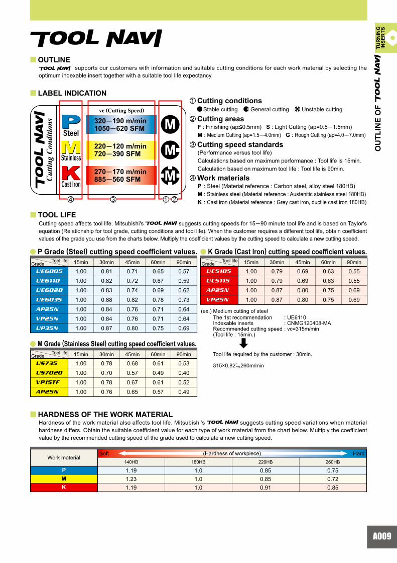
Cutting speed affects tool life. Mitsubishi's suggests cutting speeds for 15�90 minute tool life and is based on Taylor's equation (Relationship for tool grade, cutting conditions and tool life). When the customer requires a different tool life, obtain coefficient values of the grade you use from the charts below. Multiply the coefficient values by the cutting speed to calculate a new cutting speed.
Hardness of the work material also affects tool life. Mitsubishi's suggests cutting speed variations when material hardness differs. Obtain the suitable coefficient value for each type of work material from the chart below. Multiply the coefficientvalue by the recommended cutting speed of the grade used to calculate a new cutting speed.
supports our customers with information and suitable cutting conditions for each work material by selecting the optimum indexable insert together with a suitable tool life expectancy.
OUTLINE
HARDNESS OF THE WORK MATERIAL
TOOL LIFE
LABEL INDICATIONz Cutting conditions
Stable cutting General cutting Unstable cutting
x Cutting areasF : Finishing (ap<0.5mm) S : Light Cutting (ap=0.5�1.5mm)M : Medium Cutting (ap=1.5�4.0mm) G : Rough Cutting (ap=4.0�7.0mm)
c Cutting speed standards(Performance versus tool life)Calculations based on maximum performance : Tool life is 15min.Calculation based on maximum tool life : Tool life is 90min.
v Work materialsP : Steel (Material reference : Carbon steel, alloy steel 180HB)M : Stainless steel (Material reference : Austenitic stainless steel 180HB)K : Cast iron (Material reference : Grey cast iron, ductile cast iron 180HB)
P Grade (Steel) cutting speed coefficient values. K Grade (Cast lron) cutting speed coefficient values.
M Grade (Stainless Steel) cutting speed coefficient values.
(ex.) Medium cutting of steel : UE6110 : CNMG120408-MA : vc=315m/min
The 1st recommendationIndexable inserts Recommended cutting speed(Tool life : 15min.)
Tool life required by the customer : 30min.
315×0.82i260m/min
Work materialSoft Hard(Hardness of workpiece)
OU
TLIN
E O
F
Tool lifeGrade
Tool lifeGrade
Tool lifeGrade
Steel
Stainless
Cast IronCutti
ng C
ondi
tions
vc (Cutting Speed)
320�190 m/min1050�620 SFM
220�120 m/min720�390 SFM
270�170 m/min885�560 SFM
15min 30min 45min 60min 90min
15min 30min 45min 60min 90min 15min 30min 45min 60min 90min
TUR
NIN
GIN
SER
TS

A010
FYVP25N
FYUE6020
MSNX3035
SYVP25N
SYUE6020
HLUE6110
MHUE6005
HLUE6020
MHUE6020
MSUE6020
HZ HZ HL
MH MH MHUE6020 UE6020 UE6020
UE6110 UE6110 UE6110MS MS MS
UC6110 UC6110 UE6110
NX3035 NX3035 NX3035
SY SY SY
FY FY FY
NX3035 NX3035 NX3035
FHAP25N
FHUE6110
MVUE6005
SHUE6005
SHUE6020
HXUE6110
GHUE6005
HXUH6400
GHUE6020
MVUE6020
HX HX HX
GH GH GH UE6020 UE6020 UE6020
UE6110 UE6110 UE6110 MV MV MV
UC6110 UC6110 UE6110
UE6110 UE6110 UE6110
SH SH SH
FH FH FH
NX3035 NX3035 NX3035
GHUS7020
MSUS7020
SHUS735
FSNX2525
GHUS735
MSUS735
SHUS735
FSNX2525
GH
MS
SH
FS
US735
US735
US735
NX2525
HLUE6020
HLUE6020
HL
UE6020
a
y y
TURNING INSERTS
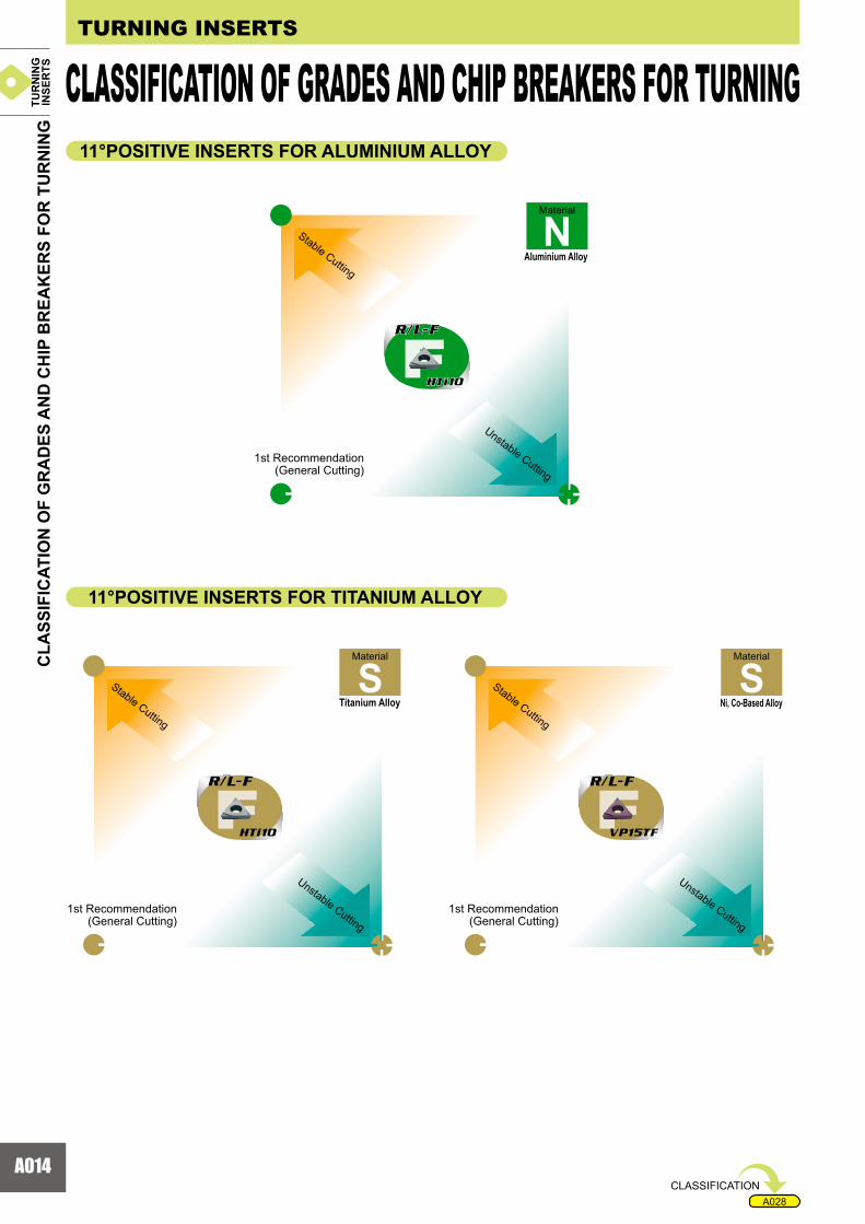
Selection of optimum inserts for turning The following diagrams show for each type of work material, the optimal combination of suitable grades andchip breakers for each application area in turning.
CUTTING CONDITIONS
Stable Cutting
General Cutting
Unstable Cutting
Continuous Cutting Constant Depth of Cut Pre-MachinedSecurely Clamped Component Cutting
Heavy Interrupted Cutting Irregular Depth of Cut Low Clamping Rigidity Cutting
Finish Cutting
Light Cutting
Medium Cutting
Heavy Cutting
Semi-Heavy Cutting
CUTTING AREA
NEGATIVE INSERTS FOR STEEL
NEGATIVE INSERTS FOR STAINLESS STEEL
(ap<0.5mm)
(ap=0.5�1.5mm)
(ap=1.5�4.0mm)
(ap=7.0�10mm)
(ap=4.0�7.0mm)
Material
Stable Cutting
Stable Cutting
Stable Cutting
1st Recommendation (General Cutting)
1st Recommendation (General Cutting)
1st Recommendation (General Cutting)
Material
Stainless Steel
Mild Steel Carbon SteelAlloy Steel
Material
Unstable Cutting
Unstable Cutting
Unstable Cutting
CLA
SSIF
ICAT
ION
OF
GR
AD
ES A
ND
CH
IP B
REA
KER
S FO
R T
UR
NIN
G
CLASSIFICATION OF GRADES AND CHIP BREAKERS FOR TURNINGTUR
NIN
GIN
SER
TS

A011
A028
FJVP10RT
FJVP15TF
FJRT9010
FJTF15
FJ
VP10RT
GJVP10RT
MSVP05RT
MJVP05RT GJ
VP15TF
MSVP15TF
MJVP15TF
MJ
VP10RT
MS
VP10RT
GJ
VP10RT
FJ
RT9010
GJRT9010
MSRT9005
MJRT9010 GJ
TF15
MSTF15
MJTF15
MJ
RT9010
MS
RT9010
GJ
RT9010
R/L-F
NX2525
MAUC5105
R/L-FNX2525
MAUC5115
R/L-FNX2525
MA
UC5115
UC5115
UC5115
UC5105
UC5105
UC5115
UC5115
NEGATIVE INSERTS FOR CAST IRON
Material
Material
Flat Top
Standard
Flat Top
Standard
Standard
Flat Top Cast Iron
Ductile Cast Iron
Ni, Co-Based Alloy
Material
Titanium Alloy
CLA
SSIF
ICAT
ION
OF
GR
AD
ES A
ND
CH
IP B
REA
KER
S FO
R T
UR
NIN
G
Stable Cutting
Stable Cutting
Stable Cutting
1st Recommendation (General Cutting)
1st Recommendation (General Cutting)
1st Recommendation (General Cutting)
Unstable Cutting
Unstable Cutting
Unstable Cutting
CLASSIFICATION
NEGATIVE INSERTS FOR TITANIUM ALLOY AND HEAT RESISTANT ALLOYS
TUR
NIN
GIN
SER
TS

A012
VP45N VP45N VP45N
UE6110 UE6110 UE6110
FVNX2525
FVUE6020
FV FV FV
UE6110
UE6020
FVNX2525
FVUE6020
FV
US735
US735
VP45N VP45N VP45N
UE6110 UE6110 UE6110
FVNX2525
FVUE6020
FV FV FV
UE6110
UE6020
FV
FVAP25N
FVAP25N
UC5105
UC5115
AP25N
UC5115
FJ
MJ
VP45N
US735
AP25N
UC5115
UC5115
VP10RT
VP10RT
TURNING INSERTS
7°POSITIVE INSERTS FOR STAINLESS STEEL 7°POSITIVE INSERTS FOR CAST IRON
7°POSITIVE INSERTS FOR HEAT RESISTANT ALLOY
7°POSITIVE INSERTS FOR STEEL Material
Material
Standard
Standard
Standard
Standard
Standard
Standard
Material
Standard
Standard
Standard
Material
Flat Top
Flat Top
Standard
Standard
Flat Top
Standard
Material
Ni, Co-Based Alloy
Cast Iron Ductile Cast Iron
Stainless Steel
Mild Steel Carbon Steel Alloy Steel
CLA
SSIF
ICAT
ION
OF
GR
AD
ES A
ND
CH
IP B
REA
KER
S FO
R T
UR
NIN
G
CLASSIFICATION OF GRADES AND CHIP BREAKERS FOR TURNING
1st Recommendation (General Cutting)
1st Recommendation (General Cutting)
1st Recommendation (General Cutting)
Stable Cutting
Stable Cutting
Stable Cutting
Stable Cutting
Stable Cutting
1st Recommendation (General Cutting)
1st Recommendation (General Cutting)
Unstable Cutting
Unstable Cutting
Unstable Cutting
Unstable Cutting
Unstable Cutting
TUR
NIN
GIN
SER
TS

A013
A028
NX2525NX2525
VP45NVP45N
VP45NVP45N
NX2525
VP45N
VP45N
MVNX3035
SVNX3035
R/L-FNX2525 MV
VP15TF
SVVP15TF
R/L-FVP15TF
MVMVMV
SVSVSV
R/L-FR/L-FR/L-F
VP15TFVP15TF
VP15TFVP15TF
VP15TFVP15TF
VP15TF
VP15TF
VP15TF
MVUE6020
SVUE6020
R/L-FNX2525 MV
VP15TF
SVVP15TF
R/L-FVP15TF
MVMVMV
SVSVSV
R/L-FR/L-FR/L-F
MVUS7020
SVUS7020
R/L-FVP15TF MV
VP15TF
SVVP15TF
R/L-FVP15TF
SV
R/L-F
MV
R/L-F
R/L-FAP25N
R/L-FVP15TF
MVAP25N
SVNX2525
MVVP15TF
SVVP15TF
SV
MV
VP15TF
US735
US735
VP15TF
VP15TF
VP15TF
11°POSITIVE INSERTS FOR STEEL
11°POSITIVE INSERTS FOR STAINLESS STEEL
11°POSITIVE INSERTS FOR CAST IRON
Material
Mild Steel
Material
Carbon Steel Alloy Steel
Material
Stainless Steel
Material
Cast Iron Ductile Cast Iron
CLASSIFICATION
CLA
SSIF
ICAT
ION
OF
GR
AD
ES A
ND
CH
IP B
REA
KER
S FO
R T
UR
NIN
G
1st Recommendation (General Cutting)
1st Recommendation (General Cutting)
1st Recommendation (General Cutting)
1st Recommendation (General Cutting)
Stable Cutting
Stable Cutting
Stable Cutting
Stable Cutting
Unstable Cutting
Unstable Cutting
Unstable Cutting
Unstable Cutting
TUR
NIN
GIN
SER
TS
A014
A028
R/L-F R/L-F
HTi10HTi10
R/L-F
HTi10
R/L-F R/L-F
HTi10 VP15TF
TURNING INSERTS
11°POSITIVE INSERTS FOR ALUMINIUM ALLOY
11°POSITIVE INSERTS FOR TITANIUM ALLOY
Material
Aluminium Alloy
Material
Ni, Co-Based Alloy
Material
Titanium Alloy
CLASSIFICATION OF GRADES AND CHIP BREAKERS FOR TURNINGC
LASS
IFIC
ATIO
N O
F G
RA
DES
AN
D C
HIP
BR
EAK
ERS
FOR
TU
RN
ING
Stable Cutting
Stable Cutting
Stable Cutting
1st Recommendation (General Cutting)
1st Recommendation (General Cutting)
1st Recommendation (General Cutting)
Unstable Cutting
Unstable Cutting
Unstable Cutting
CLASSIFICATION
TUR
NIN
GIN
SER
TS
A015
� � �
� � �
� � �
� �
� � �
FS
F
K
R/L
SR
SS
SN
� � �
� � �
�
� � � � � �
� � � � � � �
�
� �
�
�
� � �FS
F
R/L
R/L
FS
F K
R/L
SN
SS
FS
F SR
y y
y y
Dep
th o
f Cut
(mm
) D
epth
of C
ut (m
m)
Feed (mm/rev)
Breaker
Breaker
Breaker
Breaker
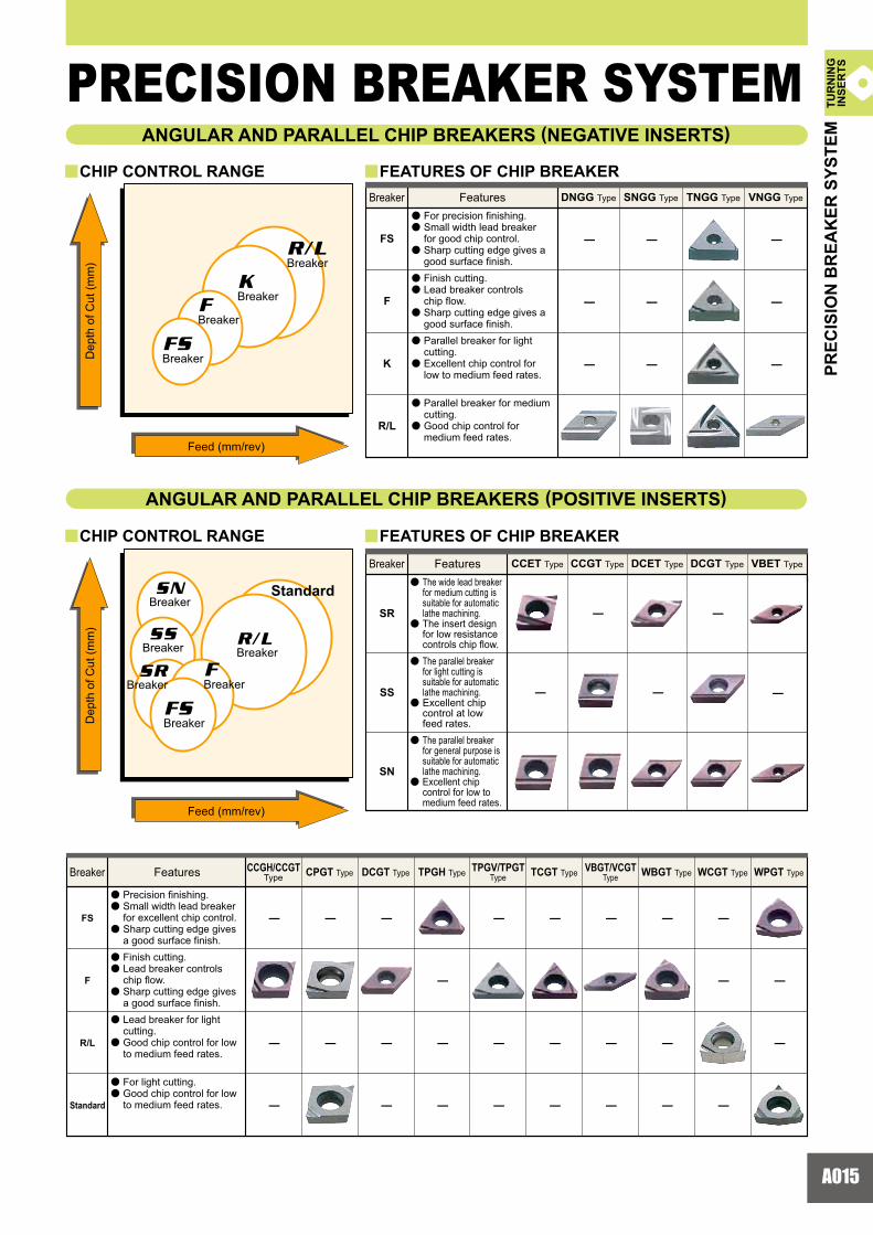
ANGULAR AND PARALLEL CHIP BREAKERS (NEGATIVE INSERTS)
CHIP CONTROL RANGE FEATURES OF CHIP BREAKERBreaker Features DNGG Type SNGG Type TNGG Type VNGG Type
a
a
a
a
a
a
a
a
a
a
For precision finishing. Small width lead breakerfor good chip control. Sharp cutting edge gives agood surface finish. Finish cutting.Lead breaker controls chip flow.Sharp cutting edge gives a good surface finish.Parallel breaker for light cutting.Excellent chip control for low to medium feed rates.
Parallel breaker for medium cutting.Good chip control for medium feed rates.
FEATURES OF CHIP BREAKER Breaker Features CCGT Type CCET Type DCET Type DCGT Type VBET Type
a
a
a
a
a
a
The wide lead breaker for medium cutting is suitable for automatic lathe machining.The insert design for low resistance controls chip flow.The parallel breaker for light cutting is suitable for automatic lathe machining. Excellent chip control at low feed rates.The parallel breaker for general purpose is suitable for automatic lathe machining.Excellent chip control for low to medium feed rates.
Feed (mm/rev)
Standard
Breaker
Breaker
Breaker
Breaker
BreakerBreaker
ANGULAR AND PARALLEL CHIP BREAKERS (POSITIVE INSERTS)
CHIP CONTROL RANGE
Breaker Features CPGT Type DCGT Type TPGH Type TPGV/TPGTType
VBGT/VCGTType
CCGH/CCGTType TCGT Type WBGT Type WCGT Type WPGT Type
a
a
a
a
a
a
a
a
a
a
Precision finishing.Small width lead breaker for excellent chip control.Sharp cutting edge gives a good surface finish.Finish cutting. Lead breaker controlschip flow. Sharp cutting edge givesa good surface finish. Lead breaker for light cutting.Good chip control for low to medium feed rates.
For light cutting.Good chip control for low to medium feed rates.
PREC
ISIO
N B
REA
KER
SYS
TEM
PRECISION BREAKER SYSTEM
Standard
TUR
NIN
GIN
SER
TS
A016
10
20
30
40
0.2 0.4 0.6 0.8 0 0
Rz(W)=Rz×0.5
a
y a
a
a
y y
y y
y
y
10
20
30
40
0.1 0.2 0.3 0.4 0.5 0.6 0
MW(93°)MW(91°)
Finished surface Same surface
roughness
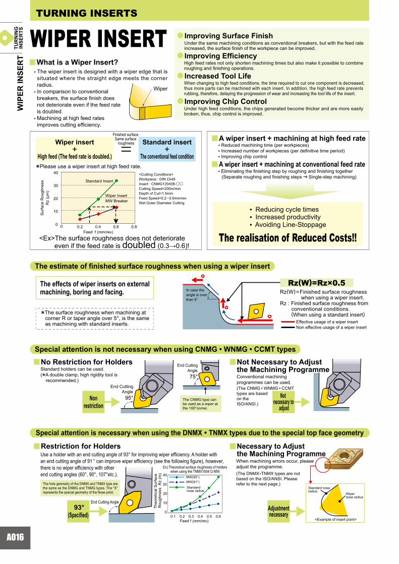
<Cutting Conditions> Workpiece : DIN Ck45Insert : CNMG120408-oo
Cutting Speed=200m/minDepth of Cut=1.5mmFeed Speed=0.2–0.6mm/revWet Outer Diameter Cutting
Sur
face
Rou
ghne
ssR
z (�
m)
Standard Insert
Wiper InsertMW Breaker
Feed f (mm/rev)
End Cutting Angle
95°
End Cutting Angle
75°
The CNMG type can be used as a wiper at the 100°corner.
Ex):Theoretical surface roughness of holders when using the TNMX160412-MW.
Feed f (mm/rev)
Theo
retic
al S
urfa
ce
Rou
ghne
ss R
z (m
)
Standardnose radius
End Cutting Angle
Standard nose radius
Wipernose radius
<Example of insert point>
Improving Surface Finish
What is a Wiper Insert?Improving Efficiency
Increased Tool Life
Improving Chip Control
Under the same machining conditions as conventional breakers, but with the feed rate increased, the surface finish of the workpiece can be improved.
High feed rates not only shorten machining times but also make it possible to combine roughing and finishing operations.
When changing to high feed conditions, the time required to cut one component is decreased, thus more parts can be machined with each insert. In addition, the high feed rate prevents rubbing, therefore, delaying the progression of wear and increasing the tool life of the insert.
Under high feed conditions, the chips generated become thicker and are more easily broken, thus, chip control is improved.
• The wiper insert is designed with a wiper edge that is situated where the straight edge meets the corner radius.
• In comparison to conventional breakers, the surface finish does not deteriorate even if the feed rate is doubled.
• Machining at high feed rates improves cutting efficiency.
Adjustmentnecessary
Necessary to Adjust the Machining ProgrammeWhen machining errors occur, please adjust the programme.(The DNMX •TNMX types are not based on the ISO/ANSI. Please refer to the next page.)
Special attention is necessary when using the DNMX • TNMX types due to the special top face geometry
Restriction for Holders
93°(Specified)
Use a holder with an end cutting angle of 93° for improving wiper efficiency. A holder with an end cutting angle of 91 ° can improve wiper efficiency (see the following figure), however, there is no wiper efficiency with other end cutting angles (60°, 90°, 107°etc.).
The hole geometry of the DNMX and TNMX type are the same as the DNMG and TNMG types. The "X" represents the special geometry of the Nose point.
Not Necessary to Adjust the Machining ProgrammeConventional machining programmes can be used.
Notnecessary to
adjust
(The CNMG • WNMG • CCMT types are based on the ISO/ANSI.)
No Restriction for HoldersStandard holders can be used.(*A double clamp, high rigidity tool is
recommended.)
Nonrestriction
Special attention is not necessary when using CNMG • WNMG • CCMT types
In case theangle is overthan 5°
The effects of wiper inserts on external machining, boring and facing.
*The surface roughness when machining at corner R or taper angle over 5°, is the same as machining with standard inserts.
The estimate of finished surface roughness when using a wiper insert
<Ex>The surface roughness does not deteriorateeven if the feed rate is doubled (0.3�0.6)!
• Reducing cycle times • Increased productivity • Avoiding Line-Stoppage
A wiper insert + machining at high feed rate
A wiper insert + machining at conventional feed rate
• Reduced machining time (per workpieces) • Increased number of workpieces (per definitive time period) • Improving chip control
• Eliminating the finishing step by roughing and finishing together(Separate roughing and finishing steps | Single-step machining)
Wiper insert +
High feed (The feed rate is doubled.)
Standard insert+
The conventional feed condition
*Please use a wiper insert at high feed rate.
The realisation of Reduced Costs!!
WIP
ER IN
SER
TTURNING INSERTS
WIPER INSERT
Effective usage of a wiper insertNon effective usage of a wiper insert
Rz(W)=Finished surface roughness when using a wiper insert.
Rz : Finished surface roughness from conventional conditions.(When using a standard insert)
Wiper
TUR
NIN
GIN
SER
TS
A017
1.20.80.4
90
0
0
0
0.01
0.01
00
0
00
0.01 -0.01
-0.01
-0.01 -0.01
0.02
0.02
0.01
0.04
0.03
0.01
0.04
0.03
0.02
0.05
0.04
0.02
0.04
0.03
0.02
0.04
0.03
0.02
0.03
0.02
0.01
0.03
0.02
0.01
0.02
0.01
0.01
0.01
0.01
0.01
0
0
0
0
75�857060�655550454020�3515105-5-10-25�-15
R2.0
R 1.2
R2.0
R1.1
6
R 1.2
R 1.2
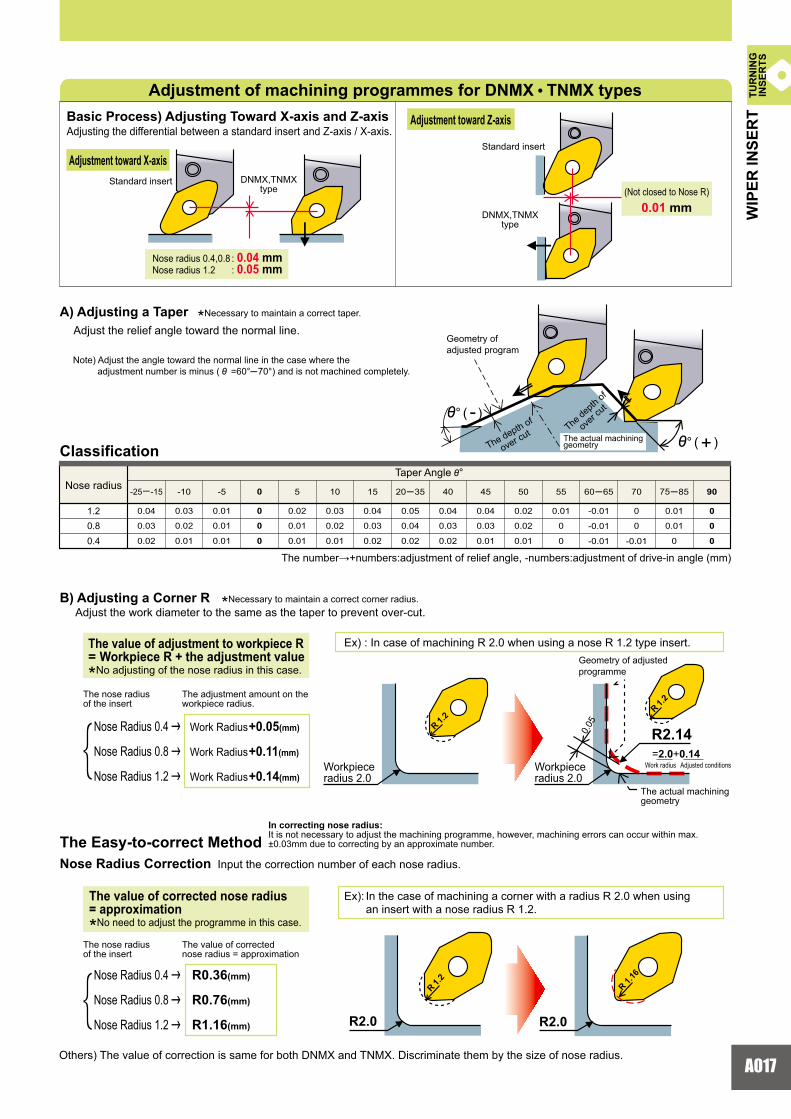
=2.0+0.14R2.140.
05
'° ( - )
'° ( + )
0.040.05
::
0.01
Ex): In the case of machining a corner with a radius R 2.0 when using an insert with a nose radius R 1.2.
Ex) : In case of machining R 2.0 when using a nose R 1.2 type insert.Geometry of adjusted programme
Workpiece radius 2.0
The actual machining geometry
Work radius Adjusted conditionsWorkpiece radius 2.0
Nose radiusTaper Angle '°
Geometry of adjusted program
The depth of
over cut The de
pth of
over
cut
The actual machining geometry
(Not closed to Nose R)
Standard insert
DNMX,TNMXtype
Standard insert
Nose radius 0.4,0.8 Nose radius 1.2
DNMX,TNMXtype
Adjustment of machining programmes for DNMX • TNMX typesBasic Process) Adjusting Toward X-axis and Z-axisAdjusting the differential between a standard insert and Z-axis / X-axis.
Adjustment toward X-axis
Adjustment toward Z-axis
Adjust the relief angle toward the normal line.
Classification
A) Adjusting a Taper *Necessary to maintain a correct taper.
Note) Adjust the angle toward the normal line in the case where the adjustment number is minus ( ' =60°�70°) and is not machined completely.
The number�+numbers:adjustment of relief angle, -numbers:adjustment of drive-in angle (mm)
B) Adjusting a Corner R *Necessary to maintain a correct corner radius. Adjust the work diameter to the same as the taper to prevent over-cut.
The nose radius of the insert
The adjustment amount on the workpiece radius.
The value of adjustment to workpiece R = Workpiece R + the adjustment value*No adjusting of the nose radius in this case.
Nose Radius 0.4 |
Nose Radius 0.8 |
Nose Radius 1.2 |
Work Radius +0.05(mm)
Work Radius
Work Radius
+0.11(mm)
+0.14(mm)
The Easy-to-correct MethodIn correcting nose radius:It is not necessary to adjust the machining programme, however, machining errors can occur within max. ±0.03mm due to correcting by an approximate number.
Nose Radius Correction Input the correction number of each nose radius.
The nose radius of the insert
Nose Radius 0.4 |
Nose Radius 0.8 |
Nose Radius 1.2 |
R0.36(mm)
R0.76(mm)
R1.16(mm)
The value of corrected nose radius = approximation
Others) The value of correction is same for both DNMX and TNMX. Discriminate them by the size of nose radius.
The value of corrected nose radius= approximation *No need to adjust the programme in this case.
WIP
ER IN
SER
TTU
RN
ING
INSE
RTS
mmmm
mm

A018
P01
P10
P20
P30
P40
M01
M10
M20
M30
M40
K01
K10
K20
K30
N01
N10
N20
N30
S01
S10
S20
S30
H01
H10
H20
H30
P
M
K
N
S
H
CVD PVD
NEW
NEW
NEW
UE6005
VP25N
AP25N
UP35N
MB710
NX55
NX99
NX2525
NX3035
NX2525
NX2525
UTi2
0T
VP45N
UTi2
0T
UTi2
0T
HTi10
MB730
MBS140
MD220
VP15TF
UP20M
VP15TF
UP20M
VP20MF V
P25N
AP25N
VP10RT
VP15TF
TF15
MBC020
MB8025
UE6110
US7020
US735
UE6020
UC5105
AP25N
VP25N
VP15TF U
C5115
UE6035
UH6400
UC6010
HTi0
5T
HTi10
VP05RT
US905
RT9005
RT9010
MB730
MB820
MB825
MB835
MBC010
TURNING INSERTS
a INDEXABLE INSERT GRADES FOR TURNINGCoated Carbide
Cermet CoatedCermet
CoatedCBN
CementedCarbide CBN PCD
(Sintered Diamond)ISO
Ste
elS
tain
less
Ste
elC
ast I
ron
Non
-Fer
rous
Met
alHe
at R
esist
ant A
lloy •
Ti A
lloy
Har
dene
d S
teel
GR
AD
ES F
OR
TU
RN
ING
GRADES FOR TURNINGTUR
NIN
GIN
SER
TS
A019
0
100
200
300
400
0 0.2 0.4 0.6 0.8 0 0.2
100
200
300
400
0.4 0.6 0.8
0 0.2
100
200
300
400
0.4 0.6 0.8 0 0.1
200
400
600
800
0.2 0.3 0.4
MP
NK
UP35N
UC6010
US7020
UE6020
UE6035
AP25N VP25N NX2525
US7020 US735
UTi20T
VP15TF VP20MF
VP45N
U5735 UH6400
UTi20T
AP25N VP25N NX2525
UC5105
HTi10
NX2525 NX3035
VP15TF UP20M
VP15TF
HTi05T HTi10
UTi20T
AP25N VP25N
MB710 MB730
UC5115
MD220
UE6110
UC5115UE6005
MBS140
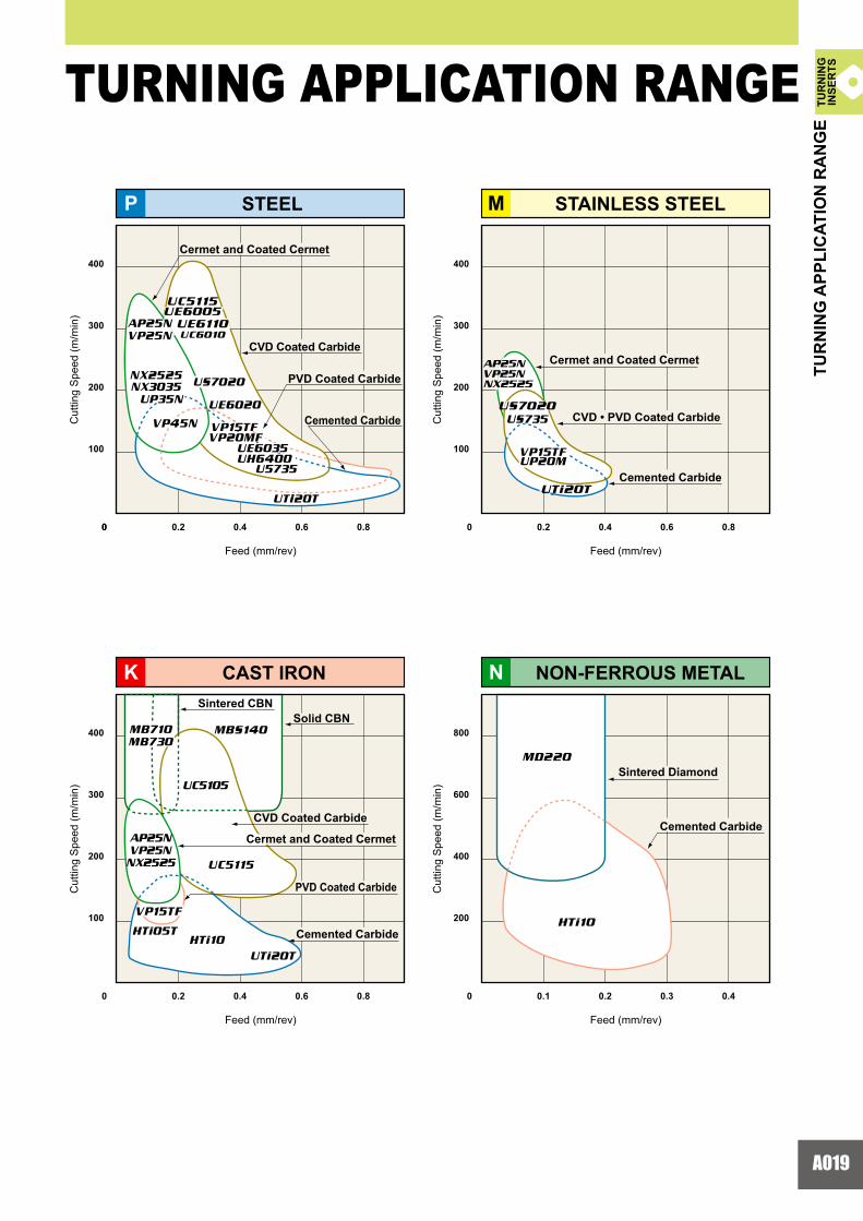
Cermet and Coated Cermet
CVD Coated Carbide
PVD Coated Carbide
Cemented Carbide
Cermet and Coated Cermet
CVD • PVD Coated Carbide
Cemented Carbide
Sintered CBNSolid CBN
Cermet and Coated Cermet
PVD Coated Carbide
Cemented Carbide
Cemented Carbide
Sintered Diamond
CVD Coated Carbide
NON-FERROUS METALCAST IRON
STAINLESS STEELSTEEL
Feed (mm/rev)
Cut
ting
Spe
ed (m
/min
)
Cut
ting
Spe
ed (m
/min
)
Feed (mm/rev)
Cut
ting
Spe
ed (m
/min
)
Cut
ting
Spe
ed (m
/min
)
Feed (mm/rev) Feed (mm/rev)
TURNING APPLICATION RANGE
TUR
NIN
G A
PPLI
CAT
ION
RA
NG
ETU
RN
ING
INSE
RTS

A020
FHAP25N
FHUE6110
MVUE6005
SHUE6005
SHUE6020
HXUE6110
GHUE6005
HXUH6400
GHUE6020
MVUE6020
MVMV
UE6010UE6010
SHSH
UE6010UE6010
FHFH
AP25NAP25N
MV
UE6110
SH
UE6110
FH
NX3035
HXHX
UE6020UE6020
GHGH
UE6010UE6010
HX
UE6020
GH
UE6110
y y
S01
M10
M20
M30
M40
US7020
US735
170(120 – 220)
100(80 – 120)
UE6005 P01
P10
P20
P30
P40
K01
K10
K20
K30
UE6110
UE6020
UE6035
UC5105
UC5115
US905
300(200 – 400)
250(150 – 400)
200(100 – 250)
150(80 – 200)
300(200 – 400)
250(150 – 300)
80(50 – 100)
S
K
P
M
NEW
US905
US7020
US735
UE6005
UE6110
UE6020
UE6035
UH6400
UC6010
UC5105
UC5115
TURNING INSERTS
SELECTION STANDARD Micro Structure of Coated Carbide UE6110
CUTTING CONDITIONS
Stable Cutting
General Cutting
Unstable Cutting
Continuous CuttingConstant Depth of CutPre-MachinedSecurely Clamped Component Cutting
Heavy Interrupted CuttingIrregular Depth of CutLow Clamping Rigidity Cutting
Finish Cutting(ap <0.5mm)
Light Cutting(ap=0.5�1.5mm)
Medium Cutting(ap=1.5�4.0mm)
Heavy Cutting(ap=7.0�10mm)
Semi-Heavy Cutting(ap=4.0�7.0mm)
CUTTING AREA
State-of-the-art “2 in 1 technology”achieves high wear resistance, high fracture resistance and high stability.
“2 in 1 technology” consists of “Nano-texture coating” and “Black-super smooth coating”.The fibrous nanoscale TiCN and the crystal growth controlled Alumina(Al2O3)in the “Nano-texture coating” give far superior fracture and wear resistance compared to conventional coatings.“Black-super smooth coating” which is used for the periphery of the insert has an extremely smooth surface and provides stable cutting for prolonged periods without abnormal damage such as welding or chipping.
Continuousand
InterruptedCutting
Continuousand
InterruptedCutting
ContinuousCutting
Stainless Steel
Steel
ContinuousCutting
InterruptedCutting
InterruptedCutting
ContinuousCutting
Cast IronDuctile Cast Iron
Heat ResistantAlloy
aTURNING
Special tough fibrous structure improves wear and fracture resistance.It covers a wide application range and thus reduces the number of tools required.
MaterialNEGATIVE
Work Material CuttingMode Recommended Grade Recommended Cutting
Speed (m/min) Application RangeISO
CO
ATED
CA
RB
IDE
( CVD
)
COATED CARBIDE (CVD)
Stable Cutting
1st Recommendation (General Cutting)
Unstable Cutting
a
a
Carbon SteelAlloy Steel
TUR
NIN
GIN
SER
TS

A021
UE6005
UC6010UE6020UE6035
US7020US735
91.0
90.590.089.5
90.589.0
1.8UE6110 90.3 2.0
2.02.22.3
UH6400 89.5 2.32.02.6
UC5105 92.2 2.0 UC5115 91.0 2.2
FS NX2525
FS NX2525
MS US7020
SH US735
SH US735
HLUE6020
GH US7020
HLUE6020
GH US735
MS US735
MA
UC5105
UC5105
UC5105
R/L-F NX2525
MA
UC5115
UC5115
UC5115
R/L-F NX2525
MS
US735
SH
US735
FS
NX2525
MA
UC5115
UC5115
R/L-F
NX2525
HL
UE6020
GH
US735
UC5115
�
�
�
US905 92.2 2.0 �
2100.33.0
1600.252.0
WNMG080408-MV(UE6020)CNMG120416-MA(UE6110)
0.15�0.22
2500.302.5
CNMA120408(UC5105)CNMG120408-MS(US7020)
20 10 UE6110 UE6020
50 100
US7020
40 80 UC5105
250 500
GRADE CHARACTERISTICS
APPLICATION EXAMPLES
Grade
Tough
TiCN-AI2O3 ThickTiCN-AI2O3 Thick
Thick
ThickThickThick
ThinThin
TiCN-AI2O3-TiN
Tough ThickAccumulated TiCN-Al2O3-Ti CompoundTiCN-AI2O3-TiN
Accumulated TiCN-Al2O3-Ti CompoundTiCN-AI2O3-TiN
TiCN-AI2O3-TiN
Ti CompoundThinTiCN-AI2O3
* 1GPa=102kg/mm2
ToughToughTough
ThickAccumulated TiCN-Al2O3-Ti CompoundToughTough
Wet cutting Wet cutting
Alloy steel(DIN 41CrMo4)
Alloy steel
Hardness (HRA)
Cutting Speed (m/min)Feed (mm/rev)Depth of Cut (mm)Coolant
Cutting Speed (m/min)Feed (mm/rev)Depth of Cut (mm)Coolant
T.R.S (GPa) Surface Composition
Insert (Grade)
Workpiece
Result
Substrate Coating LayerThickness
pieces/cornerpieces/corner
Competitor's P20 coatingCompetitor's P10 coating
UE6020 achieved 6 times longer tool life.
Wet cutting
Conventional coated grade=100, US7020=200
Wet cutting
Stainless steel(DIN X5CrNiMo1810)
Gray cast iron(DIN GG30)
Insert (Grade)
Workpiece
Result
pieces/corner
UC5105 achieved more than double tool life.
UE6110 achieved more than double tool life.
US7020 achieved two times longer tool life comparedto previous grade when turning at double cutting speed.
Previous coated grade
pieces/corner
Competitor's K01 coating Large wear
MaterialNEGATIVE
MaterialNEGATIVE
Flat Top
Standard
Standard
Flat Top
CO
ATED
CA
RB
IDE
( CVD
)
Stable Cutting
Unstable Cutting
Stable Cutting
Unstable Cutting1st Recommendation
(General Cutting) 1st Recommendation (General Cutting)
Flat Top
Standard
Cut
ting
Con
ditio
nsC
uttin
gC
ondi
tions
Stainless Steel C a s t I r o n
TUR
NIN
GIN
SER
TS

A022
S01
S10
S20
S30
VP 15 TF
K
S
P
M
VP15TF P01
P10
P20
P30
P40
VP20MF
UP20M
120(100 – 150)
120(100 – 150)
120(100 – 150)
VP15TF M01
M10
M20
M30
K01
K10
K20
K30
M40
VP20MF
UP20M
120(100 – 150)
120(100 – 150)
120(100 – 150)
VP15TF 120(100 – 150)
VP05RT
VP10RT
VP15TF
50(20 – 70)
40(20 – 50)
40(20 – 50)
a
VP05RT
VP10RT
VP15TF
VP20MF
UP20M
VP15TF
VP15TF
VP20MF
UP20M
VP15TF
a
a
TURNING INSERTS
PVD coating prolongs tool life.Coating of tools with sharp edges is possiblewithout softening or changing the quality ofthe substrate.
Coating Layer (Wear Resistance) (Thermal Shock Resistance) (Welding Resistance)
Substrate
SELECTION STANDARD TURNING
Work Material Recommended Grade Recommended Cutting Speed (m/min)
CoatingName
Steel
VP Coating
UP Coating
VP Coating
UP Coating
Cast Iron VP Coating
StainlessSteel
ISO
Heat Resistant Alloy
VP Coating
CLASSIFICATION METHOD If coated grades are desired, please specify the grade name as follows.
Substrate Symbol
Last 2 Figures of Substrate
Coating Symbol VP : VP Coating GP : GP Coating AP : AP Coating UP : UP Coating
M : UTiooT HT : HTiooTH : HTioo TF : TFoo N : CermetRT : RT90oo MF : MFoo
Application Range
CO
ATED
CA
RB
IDE
( PVD
)
COATED CARBIDE (PVD)
TUR
NIN
GIN
SER
TS
a
a
A023
900
(r)
800
700
600
50 60 70 80 (N)
ø45
ø85
ø45
ø36
ø50
800400 0
300150 75 0 2 1 0
1500500 0
1700.140.25
2000.250.5
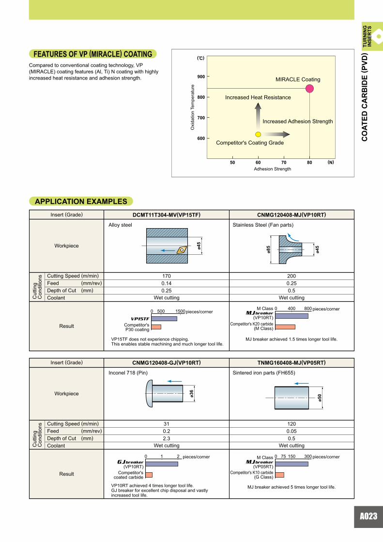
CNMG120408-MJ(VP10RT)DCMT11T304-MV(VP15TF)
310.22.3
1200.050.5
TNMG160408-MJ(VP05RT)CNMG120408-GJ(VP10RT)
VP15TF
Compared to conventional coating technology, VP (MIRACLE) coating features (Al, Ti) N coating with highly increased heat resistance and adhesion strength.
FEATURES OF VP (MIRACLE) COATING
Oxi
datio
n Te
mpe
ratu
re
Adhesion Strength
Increased Heat Resistance
Increased Adhesion Strength
Competitor's Coating Grade
MIRACLE Coating
Competitor'sP30 coating
APPLICATION EXAMPLES
Wet cutting Wet cutting
Alloy steel Stainless Steel (Fan parts)
Cutting Speed (m/min)Feed (mm/rev)Depth of Cut (mm)Coolant
Cutting Speed (m/min)Feed (mm/rev)Depth of Cut (mm)Coolant
Insert (Grade)
Workpiece
Result
pieces/cornerpieces/corner
Competitor's K20 carbide(M Class)
pieces/cornerpieces/corner
Competitor's K10 carbide(G Class)
Competitor'scoated carbide
Wet cutting Wet cutting
Inconel 718 (Pin) Sintered iron parts (FH655)
Insert (Grade)
Workpiece
Result
Cut
ting
Con
ditio
nsC
uttin
gC
ondi
tions
VP15TF does not experience chipping.This enables stable machining and much longer tool life.
MJ breaker achieved 1.5 times longer tool life.
MJ breaker achieved 5 times longer tool life.VP10RT achieved 4 times longer tool life.GJ breaker for excellent chip disposal and vastly increased tool life.
CO
ATED
CA
RB
IDE
( PVD
)
(VP10RT)
(VP10RT)
M Class
(VP05RT)
M Class
TUR
NIN
GIN
SER
TS
GJ
MJ
MJbreaker
breaker
breaker

A024
NX2525
NX3035
NX2525
K01
K10
K20
P01
P10
P20
210(170 � 230)
230(190 � 260)
250(200 � 280)
NX2525
NX55NX99
92.2
91.791.2
2.0
1.81.9
33
2533
7.8NX3035 91.5 2.1 35 7.8
7.87.8
K
P
y y
y
NEW
NX2525
NX3035
NX55
NX2525
NX99
NX3035
0 5 10 15 20 25 30 35
0.05
0.10
0.15
0.20
0.25
0.30
0.35
30252015105
0.1
0.05
0
0 500 1,000 1,500 2,000
NX2525
NX3035
TURNING INSERTS
SELECTION STANDARDaTURNING
Micro-Structure of NX2525
a
<Cutting Conditions>Workpiece : DIN Ck45Insert : CNMG120408-pp
vc=250m/minap=1.0mmf=0.15mm/revWet CuttingExternal Continuous Cutting
<Cutting Conditions>Workpiece : DIN GG30Insert : CNMG120408vc=100m/minap=1.5mmf=0.3mm/revWet Cutting
* 1GPa=102kg/mm2, 1W/m • K=2.39×10⁻³cal/cm • sec • r
CUTTING PERFORMANCE
GRADE CHARACTERISTICS
Steel
Cast IronDuctile Cast Iron
<Cutting Conditions>Workpiece : DIN 41CrMo4Insert : CNMG120408-pp
vc=200m/minap=1.5mmf=0.2mm/revWet CuttingInterrupted Cutting
Cutting Performance
Hardness (HRA) T.R.S (GPa) Thermal Conductivity(W/m • K)
Thermal Expansion(×10-6/K)
GradeSubstrate
Cutting Time (min)
Flan
k W
ear (
mm
)
Competitor's K10Cemented Carbide
Cutting Time (min)
Flan
k W
ear (
mm
)
Steel, Continuous Cutting (Wet)
Cast Iron, Continuous Cutting
NX2525 has high hardened Ti compound particles within it's microstructure therefore the grade has both excellent wear and fracture resistance properties.
Micro-Structure of NX3035
aNX3035 uses a special alloy substrate in the metal binder phase to deliver highly improved thermal shock resistance.
*
Competitor's P20 coated cermet
Competitor'smicro grain P20 cermet
Cutting Time (min) Number of Impacts
Competitor'smicro grain P20 cermetCompetitor'sP20 coated cermet
ContinuousCutting
InterruptedCutting
Finishing
Work Material CuttingMode Recommended Grade Recommended Cutting
Speed (m/min) Application RangeISO
Cutting Speed : vc Depth of Cut : apFeed : f
CER
MET
CERMETa
a
a
a
The optimized alloy structure and special alloy binder improves both wear and fracture resistance.It covers a wide application range and reduces the number of tools required.NX3035 for wet cutting.NX2525 for dry cutting.
TUR
NIN
GIN
SER
TS
Steel, Interrupted Cutting

A025
AP25N
AP25N
P01
P10
P20
P30
K01
K10
K20
UP35NVP45N
220(170 � 250)
180(140 � 200)
280(200 � 320)
K
P
0.18 0.20 0.22 0.24 0.26
10002000
10002000
10002000
10002000
10002000
yy
y
VP25N
UP35N
VP45N
AP25N
VP25N
AP25N
50
100
5 10 15 20
0.1
0.2
0.3
AP25N
AP25N
UP35N
aCoated cermet (PVD coating) has superior wear and fracture resistance, and therefore provides a stable cutting performance.
Micro-Structure of AP25N
a
a
SubstrateMicro Grain Cermet NX2525 (wear resistance and fracture resistance)
Coating LayerOuter layer is TiN (Welding resistance)Middle layer is (Ti, Al) N Compound.(wear resistance thermal shock resistance)
Num
ber o
f Pas
ses
<Cutting Conditions>Workpiece : DIN 41CrMo4 (HB230)Insert : CNMG120408-pp
vc=200m/minap=2.0mmf=0.3mm/revWet Cutting
Competitor's PVD
Cermet A
ConventionalCermet
SELECTION STANDARDaTURNING
Steel
Cast IronDuctile Cast Iron
CUTTING PERFORMANCE
Flan
k W
ear (
mm
)
<Cutting Conditions>Workpiece : DIN 41CrMo4 (HB230)Insert : CNMG120408-pp
vc=300m/minap=0.5mmf=0.2mm/revWet Cutting
ConventionalCermet
Competitor'sPVD Cermet A
Cutting Time (min)
<Cutting Conditions>Workpiece : DIN 41CrMo4 (HB230)Insert : CNMG120408-MAvc=200m/minap=1.5mmDry Cutting
Normal WearChipping
Cutting Performance
Wear Resistance for Wet Cutting
Fracture Resistance for Interrupted Cutting
Thermal Shock Resistance for Interrputed Cutting
Work Material CuttingMode Recommended Grade Recommended Cutting
Speed (m/min) Application RangeISO
ContinuousCutting
InterruptedCutting
Finishing
Feed(mm/rev)No. of Impacts
ConventionalCermet
Cutting Speed : vc Depth of Cut : apFeed : f
CO
ATED
CER
MET
COATED CERMET TUR
NIN
GIN
SER
TS

A026
P M
KN
NP
K
M
S
S
M
UTi20T
UTi20T
HTi05T
HTi10
UTi20T
HTi10 600(400 � 800)
60(40 � 80)
50(40 � 70)
70(50 � 100)
100(60 � 130)
120(80 � 150)
100(50 � 150)
100(50 � 150)
RT9010
RT9005
TF15
P10
P20
P30
M10
M20
M30
K01
K10
K20
K30
P
K
N
S
N01
N10
N20
N30
S01
S10
S20
S30
100(60 � 130)
UTi20THTi05THTi10RT9005RT9010TF15
90.592.592.092.292.091.5
387979797971
5.54.54.64.54.65.3
520600630600630580
2.01.52.02.02.22.5
WC-Co
WC-TiC-TaC-Co
WC-Co
UTi2
0T
UTi2
0T
RT9005
300
200
10080
6020
10 20 30 40 60 100
UTi20T
300
200
10080
60
10 20 30 40 60 100
400
UTi20T
HTi10 HTi05T
HTi10
TF15
RT9010
HTi0
5T
HTi10
UTi2
0T
Heat-resistant alloy, Ti alloyHigh heat resistance and wear resistance.
TURNING INSERTS
UTi grades are available for steel and cast iron. HTi grades are available for non-ferrous and non-metal materials and are also suitable for cast iron.
SELECTION STANDARD 10!m 10!mP,M Class Grade (WC-TiC-TaC-Co)K Class Grade (WC-Co)
MAIN COMPONENT AND APPLICATION
GRADE CHARACTERISTICS
P series for steel cutting, K series for cast iron cutting and M series for stainless cutting.
Steel
Cast Iron
Stainless Steel
Non-Ferrous Metal
Heat-resistant AlloyTi Alloy
Heat / deformation resistance.
High rigidity and wear resistance.
Carbon steel, alloy steel, stainless steel and cast iron
Tool Life (min)
Cut
ting
Spe
ed (m
/min
)
a <Cutting Conditions> DryWorkpiece : DIN Ck45 220HBTool Life Standard : VB=0.3mmDepth of Cut : 1.5mmFeed : 0.3mm/revHolder : CSBNR2525M43Insert : SNMG120408
Tool Life (min)
Cut
ting
Spe
ed (m
/min
) a
V-T Diagram (P Grade)
V-T Diagram (K Grade) <Cutting Conditions> DryWorkpiece : DIN GG30 200HBTool Life Standard : VB=0.3mmDepth of Cut : 1.5mmFeed : 0.3mm/revHolder : CSBNR2525M43Insert : SNMN120408
* 1GPa=102kg/mm2, 1W/m • K=2.39×10⁻³cal/cm • sec • r
Work Material
MainComponent Characteristics
Recommended Grade Recommended Cutting Speed (m/min) Application RangeISO
ISO
ISO Hardness(HRA)Grade
ThermalConductivity
(W/m•K)
ThermalExpansion(x10-6/K)
Young'sModulus(GPa)
T.R.S(GPa)
Cast iron, non-ferrous metals, and non-metal
CEM
ENTE
D C
AR
BID
E
CEMENTED CARBIDE
* * *
TUR
NIN
GIN
SER
TS
Work Material
aTURNING
a

A027
HTi10
SF10
MF10
TF15
MF20
TF15
HTi10
MF10TF15
TF15MF20MF30
MF10MF20
SF10MF07
UF20
UF30
14.9
14.5
14.2
14.2
13.9
14.9
14.6
92.7
92.0
93.0
91.0
92.0
91.5
90.0
3.2
3.8
4.0
4.0
4.4
2.5
2.9
K10
K01
K01
K10
K20
K10
K20
u
u
e
e
e
e
e
u
e u
u
u
u
e
e
u
u
u
e
MF30 13.7 90.7 4.3 K20 u e e
e
e
e
e
MF07 14.7 93.2 3.9 K01
u
a
2010 30 40 50
0.1
0.2
0.3
0.4
TF15
9.0
0.6
Micro-Structure of TF15Micro-Structure of MF10
MICRO-GRAIN CEMENTED CARBIDE
Compared to general cemented carbide, micro-grain alloy has higher wear resist- ance and higher toughness.
SELECTION STANDARD CUTTING PERFORMANCE
PCB Drill
Solid Carbide Drill Turning Inserts Milling Inserts
Solid End Mill
Gear Hob ReamerTap etc.
Cutting Tool Recommended Grade Work Material
Non-Metal
Steel • Cast Iron
Steel • Cast Iron
Steel • Cast Iron, etc.
Co HSS
Powder HSS
Perip
hera
l Edg
e Fl
ank
Wea
r (m
m)
Cutting Length (m)
<Cutting Conditions> Workpiece : Die steel (40HRC)Tool :&6mm,4 flutes Helical Angle : 30° vc=30m/minn=1,600min-1
fz=0.02mm/toothvf=128mm/minDepth of Cut in the Axial Direction=9.0mm Depth of Cut in the Radial Direction=0.6mm Down Cut, Dry
ISO
1GPa=102kg/mm2
GRADE CHARACTERISTICS
Grade Wear Resistance
FractureResistance
Grade Characteristics
Specific Gravity (Gpa)Hardness *
*
CorrosionResistance(HRA) T.R.S
MIC
RO
-GR
AIN
CEM
ENTE
D C
AR
BID
E
2�m 2�m
TUR
NIN
GIN
SER
TS

A028
12°
12°
8°
9°
16°
15° 0.2
15°
14°
15°
15°
14°
0.3
0.34
0.2
0.16
7°
8°25°
10°25°
15°
18°
0.167°
18°
15°
M
G
M
FH
FS
FJ
PK
R/L-F
SH
SA
SW
FYNEW
TUR
NIN
GIN
SER
TS
Double sided chipbreaker.Stable chip control even at small depth of cut.
First recommendation for finishing general steel and alloy steel
Double sided chipbreaker.Stable chip control even at a small depth of cut.Sharp edge gives best performance.
First recommendation for finishing stainless steelAlternative chipbreaker for finishing mild steel
Double sided chipbreaker.Effectively controls adhesive chips.Suitable for mild steel finishing.
First recommendation for finishing mild steel
Double sided chipbreaker.Ideal for heat-resistant alloy and titanium alloy.The sharp edge produces good cutting surface.The curved edge allows smooth chip discharge.
First recommendation for finishing difficult-to-cut materials
Double sided chipbreaker.G class insert tolerance is suitable for workpieces requiring close dimensional tolerances.Stable chip control even at a small depth of cut.
Alternative chipbreaker for finishing general steel and alloy steel
Double sided chipbreaker.Lead chipbreaker controls chip flow. The sharp edge produces a good surface finish.
Finishing
Double sided chipbreaker.Can be used at low depths of cut and high feed rates.The curved edge allows smooth chip discharge.Recommended for workpieces in the 160�250HB range.
First recommendation for light cutting of general steel and alloy steel
Double sided chipbreaker.Superior chip control at small depth of cuts.Covers copying and back turning with the wavy edge.Recommended for workpieces in the 200�300HB range.
Alternative chipbreaker for light cutting of general steel and alloy steel
Breaker Name and
PictureFeatures Cross Section
Geometry
CLA
SSIF
ICAT
ION
App
licat
ion
Tole
ranc
e
NEGATIVE INSERTS WITH HOLE
TURNING INSERTS
CLASSIFICATION
Double sided chipbreaker.The wiper allows up to double the feed rate.Wiper design for increased productivity and improved surface finish.
Wiper insert for light cutting of general steel and alloy steel
Flank
Nose
Flank
Nose
Flank
Nose
Flank
Nose
Flank
Flank
Nose
Flank
Nose
Flank
Nose
Flank
Nose
Fini
sh C
uttin
gLi
ght C
uttin
g

A029
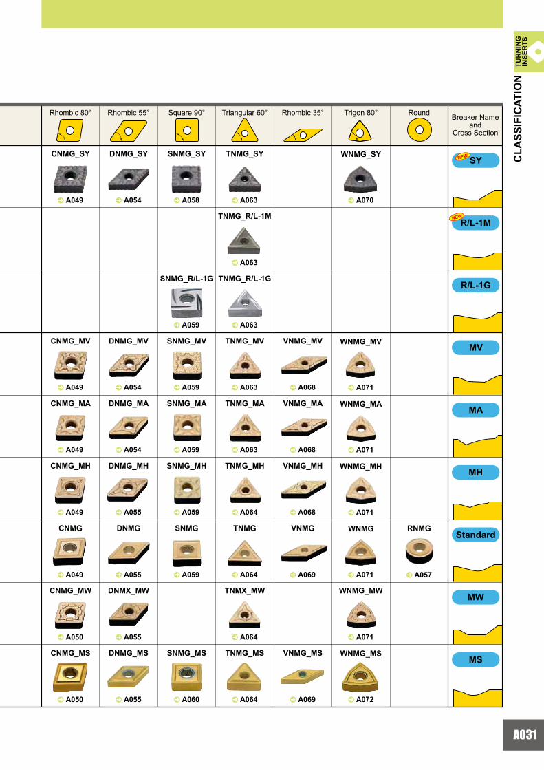
^ A048 ^ A053 ^ A058 ^ A062 ^ A068 ^ A070
FH
FS
FJ
PK
R/L-F
SH
SA
SW
CNMG_FH DNMG_FH SNMG_FH TNMG_FH VNMG_FH WNMG_FH
^ A048 ^ A053 ^ A058 ^ A062 ^ A068 ^ A070
CNMG_FS DNMG_FS SNMG_FS TNMG_FS VNMG_FS WNMG_FS
^ A048 ^ A053 ^ A058 ^ A062 ^ A070
CNMG_FY DNMG_FY SNMG_FY TNMG_FY WNMG_FY
^ A048 ^ A053 ^ A068
CNGG_FJ DNGG_FJ VNGG_FJ
^ A048 ^ A053 ^ A058 ^ A062
CNGG_PK DNGG_PK SNGG_PK TNGG_PK
^ A062
TNGG_R/L-F
^ A048 ^ A053 ^ A058 ^ A062 ^ A068 ^ A070
CNMG_SH DNMG_SH SNMG_SH TNMG_SH VNMG_SH WNMG_SH
^ A049 ^ A054 ^ A058 ^ A063 ^ A070
CNMG_SA DNMG_SA SNMG_SA TNMG_SA WNMG_SA
^ A049 ^ A054 ^ A063 ^ A070
CNMG_SW DNMX_SW TNMX_SW WNMG_SW
FYNEW
TUR
NIN
GIN
SER
TS
Breaker Nameand
Cross Section
Rhombic 80° Rhombic 55° Square 90° Triangular 60° Rhombic 35° Trigon 80° Round
CLA
SSIF
ICAT
ION

A030
0.2
02
02
0.2
6°22°
0.26°
22°
0.2
6°22°
0.2
11°30°
10°
10°
15°
15°
0.3516°
0.2516°
0.215°
0.2515°
0.319°
0.2519°
0.525°
15°
0.525°15°
M
M
MV
MA
MH
MW
MS
R/L-1G
SY
R/L-1M
NEW
NEW
TUR
NIN
GIN
SER
TS
Breaker Name and
PictureFeatures Cross Section
Geometry
CLA
SSIF
ICAT
ION
App
licat
ion
Tole
ranc
e
NEGATIVE INSERTS WITH HOLE
TURNING INSERTS
CLASSIFICATIONLi
ght C
uttin
gM
ediu
m C
uttin
g
Double sided chipbreaker.Effectively controls adhesive chips.Suitable for mild steel light cutting.
First recommendation for light cutting of mild steel
Double sided chipbreaker.Parallel chipbreaker controls chip flow.Suitable for finish-light cutting.Moulded chipbreaker.
Alternative chipbreaker for light cutting of general steel and alloy steel
Double sided chipbreaker.Parallel chipbreaker controls chip flow.Suitable for finish-light cutting.Precision chipbreaker.
Alternative chipbreaker for light cutting of general steel and alloy steel
Double sided chipbreaker.Suitable for medium to light cutting.Breaker geometry appropriate for copying and back turning.Positive land provides sharp cutting action.
First recommendation for medium cutting of general steel and alloy steel
Double sided chipbreaker.Positive land provides sharp cutting action.
Alternative chipbreaker for medium cutting of general steel and alloy steelFirst recommendation for light cutting cast iron
Double sided chipbreaker.Flat land offers high edge strength.
Alternative chipbreaker for medium cutting of general steel and alloy steelFirst recommendation for medium - heavy cutting of mild steel
Double sided chipbreaker.Flat land offers high edge strength.
First recommendation for medium cutting of cast ironAlternative chipbreaker for medium cutting of general steel and alloy steel
Double sided chipbreaker.The wiper allows up to two times higher feed.A wide chip pocket prevents chip jamming.
Wiper insert for medium cutting general steel and alloy steel
Double sided chipbreaker.The sharp edge gives best performance.
First recommendation for medium cutting of stainless steel and mild steelFirst recommendation for semi-heavy cutting of difficult-to-cut materials
Flank
Nose
Flank
Nose
Flank
Nose
Flank
Nose
Flank
Nose
Flank
Nose
Flank
Flank
Flank
Nose
StandardStandard
A031
^ A049 ^ A054 ^ A058 ^ A063 ^ A070
CNMG_SY DNMG_SY SNMG_SY TNMG_SY WNMG_SY
^ A071
WNMG_MV
^ A071
WNMG_MA
^ A071
WNMG_MH
^ A063
TNMG_R/L-1M
^ A059 ^ A063
SNMG_R/L-1G TNMG_R/L-1G
^ A059 ^ A063
SNMG_MV TNMG_MV
^ A049 ^ A054 ^ A068
CNMG_MV DNMG_MV VNMG_MV
^ A068
VNMG_MA
^ A068
VNMG_MH
^ A049 ^ A054 ^ A059 ^ A063
CNMG_MA DNMG_MA SNMG_MA
^ A049 ^ A055 ^ A059
CNMG_MH DNMG_MH SNMG_MH
TNMG_MA
^ A064
TNMG_MH
^ A049 ^ A055 ^ A059 ^ A064 ^ A069 ^ A071
CNMG DNMG SNMG TNMG VNMG WNMG
^ A050 ^ A055 ^ A064 ^ A071
CNMG_MW DNMX_MW TNMX_MW WNMG_MW
^ A057
RNMG
^ A050 ^ A055 ^ A064 ^ A072
CNMG_MS DNMG_MS
^ A060
SNMG_MS
^ A069
VNMG_MSTNMG_MS WNMG_MS
R/L-1G
MV
MW
MH
MA
SY
R/L-1M
NEW
NEW
MS
TUR
NIN
GIN
SER
TS
Breaker Nameand
Cross Section
Rhombic 80° Rhombic 55° Square 90° Triangular 60° Rhombic 35° Trigon 80° Round
CLA
SSIF
ICAT
ION
Standard

A032
0.2
0.2
15°
0.214°
15°
0.2514°
9°
13°
9°
13°
0.34
0.34
0.16
0.16
18°
18°
18°
18°
M
M
MJ(M)
MJ(G)
R/L-ES
R/L-2M
R/L-2G
R/L
GH
GJ
MJ(M)
NEW
M
G
G
TUR
NIN
GIN
SER
TSTURNING INSERTS
Double sided chipbreaker.Ideal for heat-resistant alloy and titanium alloy.The sharp edge produces a good surface finish.The curved edge allows smooth chip discharge.
First recommendation for medium cutting of difficult-to-cut materials
Double sided chipbreaker, single sided chipbreaker (D type, V type).The sharp edge produces a good surface finish.Ideal for heat-resistant alloy and titanium alloy.The curved edge allows smooth chip discharge.
First recommendation for medium cutting of difficult-to-cut materials
Double sided chipbreaker.Good balance of edge strength and sharpness.Right- or left-hand breaker for unidirectional chip control.
Alternative chipbreaker for medium cutting of stainless steel
Double sided chipbreaker.Parallel chipbreaker controls chip flow.Suitable for light to medium cutting.Moulded chipbreaker.
Alternative chipbreaker for medium cutting of general steel and alloy steel
Double sided chipbreaker.Parallel chipbreaker controls chip flow.Suitable for light to medium cutting.
Alternative chipbreaker for medium cutting of general steel and alloy steel
Double sided chipbreaker.Parallel chipbreaker.Good chip control for medium feed rates.
Medium cutting
Double sided chipbreaker.For interrupted cuts and removing scale.A combination of a wide land and large chip pocket allows high feed rates.
First recommendation for semi-heavy cutting of general steel and alloy steel
Double sided chipbreaker.Excellent balance of edge sharpness and strength.Edge geometry with high face wear resistance.
First recommendation for semi-heavy cutting of difficult-to-cut materials
CLASSIFICATIONBreaker Name
andPicture
Features Cross SectionGeometry
CLA
SSIF
ICAT
ION
App
licat
ion
Tole
ranc
e
NEGATIVE INSERTS WITH HOLE
Flank
Nose
Flank
Nose
Flank
Nose
Flank
Nose
Flank
Flank
Flank
Flank
TUR
NIN
GIN
SER
TSC
LASS
IFIC
ATIO
NTURNING INSERTS
CLASSIFICATIONBreaker Name
andPicture
Features Cross SectionGeometry
App
licat
ion
Sem
i-hea
vy C
uttin
gM
ediu
m C
uttin
g

A033
MJ(M)
MJ(G)
R/L-ES
R/L-2G
R/L
GH
GJ
^ A050 ^ A055 ^ A065 ^ A069 ^ A072
CNMG_MJ DNMG_MJ TNMG_MJ VNMG_MJ
^ A050 ^ A055 ^ A069
^ A065
TNMG_R/L-ES
^ A065
TNMG_R/L-2M
^ A065
TNMG_R/L-2G
^ A056 ^ A060 ^ A065 ^ A069
DNGG_R/L SNGG_R/L TNGG_R/L VNGG_R/L
^ A051 ^ A056 ^ A060 ^ A066 ^ A072
CNMG_GH DNMG_GH SNMG_GH TNMG_GH WNMG_GH
^ A051 ^ A056 ^ A072
CNMG_GJ DNMG_GJ WNMG_GJ
R/L-2M
CNGG_MJ DNGM_MJ VNGM_MJ
WNMG_MJ
NEW
NEW
TUR
NIN
GIN
SER
TS
Breaker Name and
Cross Section
Rhombic 80° Rhombic 55° Square 90° Triangular 60° Rhombic 35° Trigon 80° Round
CLA
SSIF
ICAT
ION

A034
0.42
0.5
0.68
0.9
21°
20°
0.32
20°
0.6820°
15°
0.915°
0.3415°
0.27
0.30
16°
23°
0°
0°
25°
M
HL
HM
HV
HCS
HX
M
G
TUR
NIN
GIN
SER
TS
Single sided chipbreaker.Covers the medium range of the heavy cutting region.Owing to the straight edge and chamfer, it gives a balance of sharpness and strength.Variable land and a wavy chipbreaker for good chip control.
First recommendation for heavy cutting of general steel and alloy steel
Single sided chipbreaker.Covers the upper end of the heavy cutting region.Wide land and large chamfer offer high edge strength.A wide chipbreaker prevents chip jamming.
Alternative chipbreaker for heavy cutting of general steel and alloy steel
Single sided chipbreaker.Covers the upper end of the heavy cutting region.Double groove chipbreaker geometry for chip control over a wide application area.One groove near the edge is for chip control at small depths of cut, the other inside groove is for larger depths of cut.
Alternative chipbreaker for heavy cutting of general steel and alloy steel
Double sided flat insert.Most effective for unstable machining due to its high edge strength.
First recommendation for heavy cutting of cast iron
Double sided flat insert.Most effective for unstable machining due to its high edge strength.Can be used on workpieces requiring close tolerances due to G class insert tolerance.
For cast iron
Breaker Name and
PictureFeatures Cross Section
Geometry
CLA
SSIF
ICAT
ION
App
licat
ion
Tole
ranc
e
NEGATIVE INSERTS WITH HOLE
TURNING INSERTS
CLASSIFICATION
Flank
Flank
Flank
Nose
Nose
Flank
Nose
Flank
Nose
Nose
Hea
vy C
uttin
gFo
r Cas
t Iro
n
Single sided chipbreaker.Cover the lower end through to the medium range of the heavy cutting region.The curved edge and narrow chamfer allow good chip control and sharp cutting action.Teardrop dots provided along the cutting edge ensures chip control even with variable depths of cut.
Alternative chipbreaker for heavy cutting of mild steel and stainless steel
Single sided chipbreaker.Covers the lower end of the heavy cutting region.The curved edge and narrow chamfer allow good chip control and sharp cutting action.Dots on the nose radius ensure chip control at low depths of cut.
First recommendation for heavy cutting of mild steel and stainless steel
Flat Top(M)
Flat Top(G)
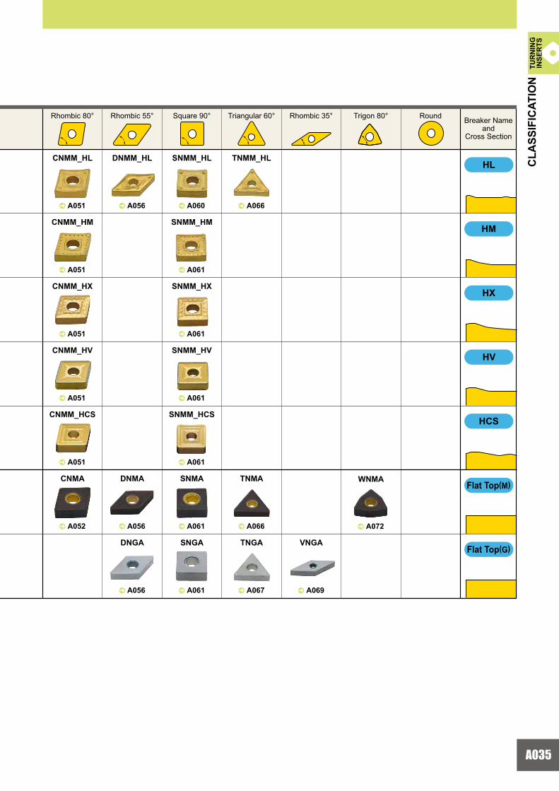
A035
^ A051 ^ A056 ^ A060 ^ A066
CNMM_HL
^ A051
CNMM_HM
^ A061
SNMM_HM
^ A051
CNMM_HX
DNMM_HL SNMM_HL TNMM_HL
^ A072
WNMA
^ A061
SNMM_HX
^ A061
SNMM_HV
^ A051
CNMM_HV
^ A051 ^ A061
CNMM_HCS SNMM_HCS
^ A052 ^ A056 ^ A061
CNMA DNMA SNMA
^ A066
TNMA
^ A056 ^ A061 ^ A067 ^ A069
DNGA SNGA TNGA VNGA
HX
HV
HCS
HL
HM
TUR
NIN
GIN
SER
TS
Breaker Nameand
Cross Section
Rhombic 80° Rhombic 55° Square 90° Triangular 60° Rhombic 35° Trigon 80° Round
CLA
SSIF
ICAT
ION
Flat Top(M)
Flat Top(G)

A036
20°
20°
0.1
13°
18°10°
0.118°10°
0.1620°8°
0.1620°8°
30°
8°
18°
0.1625°
0.1625°
E
M
M
G
R/L-MV
R/L-SR
R/L-SN
R/LW-SN
MV
R/L-F
SVNEW
TUR
NIN
GIN
SER
TS
Lead chipbreaker controls chip flow. Sharp cutting edge gives a good surface finish.
Finishing
Large rake angle provides sharp cutting action.A peninsular dot ensures chip control at depths of cut under 1mm.
Light cutting of general steel, alloy steel, mild steel and stainless steel
A positive insert with a large rake angle achieves sharp cutting edge performance.The double breakers and round-shaped dots in the rake face achieve a wide range of chip discharge.
Medium cutting of general steel, alloy steel, mild steel and stainless steel
A positive insert with a large rake angle achieves sharp cutting edge performance.The double breakers and round-shaped dots in the rake face achieve a wide range of chip discharge.
Medium cutting of general steel, alloy steel, mild steel and stainless steel
A wide lead chipbreaker.Insert designed for low resistance chip control.
Medium cutting of automatic lathe machining
A parallel chipbreaker.Excellent chip control for low to medium feed rates.
Medium cutting of automatic lathe machining
A parallel chipbreaker.Excellent chip control for low to medium feed rates.The wiper produces good cutting surface.
Medium cutting of automatic lathe machining
Breaker Name and
PictureFeatures Cross Section
Geometry
CLA
SSIF
ICAT
ION
App
licat
ion
Tole
ranc
e
TURNING INSERTS
CLASSIFICATION5° POSITIVE INSERTS WITH HOLE
Flank
Nose
Flank
Nose
Flank
Flank
Flank
Flank
Flank
Nose
Balance of edge strength and sharpness due to a combination of a flat land and large rake angle.
Medium cutting of general steel, alloy steel and stainless steel
Flank
Nose
Fini
sh C
uttin
gLi
ght C
uttin
gM
ediu
m C
uttin
g
Standard
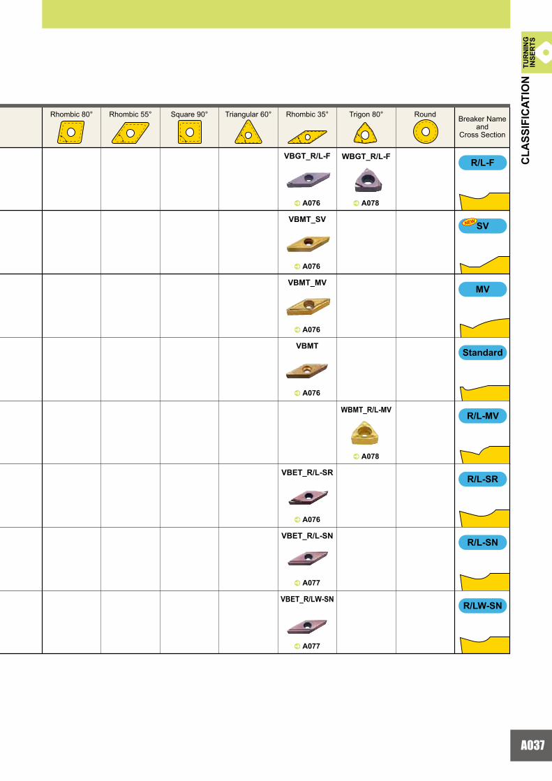
A037
^ A078^ A076
VBGT_R/L-F WBGT_R/L-F
^ A078
WBMT_R/L-MV
^ A076
VBMT_SV
^ A076
VBMT_MV
^ A076
VBMT
^ A076
VBET_R/L-SR
^ A077
VBET_R/L-SN
^ A077
VBET_R/LW-SN
MV
R/L-MV
R/LW-SN
R/L-SR
R/L-F
SVNEW
R/L-SN
TUR
NIN
GIN
SER
TS
Breaker Nameand
Cross Section
Rhombic 80° Rhombic 55° Square 90° Triangular 60° Rhombic 35° Trigon 80° Round
CLA
SSIF
ICAT
ION
Standard

A038
8°
14°
14°
15°
14°
18°
17°
0.1216°
8°
0.1220°12°
8°
18°
0.18
0.18
0.118°
0.118°
20°12°
20°12°
0.2
0.2
18°7°
18°7°
FV
FJ
R/L-F
R/L
SV
SW
R/L-SS
MV
MW
M
M
M
G
G
TUR
NIN
GIN
SER
TS
Breaker Nameand
PictureFeatures Cross Section
Geometry
CLA
SSIF
ICAT
ION
App
licat
ion
Tole
ranc
e
TURNING INSERTS
CLASSIFICATION7° POSITIVE INSERTS WITH HOLE
Suitable for low depths of cut and low feed rates. Sharp cutting edge and low resistance design achieves excellent cuttingperformance.
Finishing of general steel, alloy steel and stainless steel
Ideal for heat-resistant alloy and titanium alloy. The sharp edge produces a good surface finish. The curved edge allows smooth chip discharge.
Finishing of difficult-to-cut materials
Lead chipbreaker controls chip flow. Sharp cutting edge gives a good surface finish.
Finishing
Lead chipbreaker. Excellent chip control at low feed rates.
Finishing
Large rake angle provides sharp cutting action. A peninsular dot ensures chip control at depths of cut under 1mm.
Light cutting of general steel, alloy steel, mild steeland stainless steel
The wiper allows up to double the feed rate.Positive land improves sharpness.
Light cutting of general steel, alloy steel, mild steeland stainless steel
A parallel chipbreaker. Excellent chip control at low feed rates.
Light cutting of automatic lathe machining
A positive insert and the large rake angle achieve sharp cutting edge performance.The double breakers and round shape in the rake face achievea wide range of chip discharge.
Medium cutting of general steel, alloy steel, mild steeland stainless steel
Balance of edge strength and sharpness due to a combination of a flat landand large rake angle.
Medium cutting of general steel, alloy steeland stainless steel
Standard
The wiper allows up to double the feed rate.A wide chip pocket prevents chip jamming.
Medium cutting of general steel, alloy steel, mild steeland stainless steel
Flank
Nose
Flank
Flank
Flank
Flank
Nose
Flank
Nose
Flank
Nose
Flank
Nose
Flank
Nose
Flank
Nose
Fini
sh C
uttin
gLi
ght C
uttin
gM
ediu
m C
uttin
g
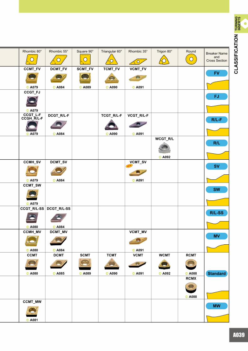
A039
^ A079
CCMT_FV
^ A084
DCMT_FV
^ A089
SCMT_FV
^ A090
TCMT_FV
^ A091
VCMT_FV
^ A079
CCGT_FJ
^ A079
CCGT_L-FCCGH_R/L-F
^ A084
DCGT_R/L-F
^ A090
TCGT_R/L-F
^ A091
VCGT_R/L-F
^ A091
VCMT_SV^ A092
WCGT_R/L
^ A079
CCMH_SV
^ A079
CCMT_SW
^ A080
CCGT_R/L-SS
^ A084
DCMT_SV
^ A084
DCGT_R/L-SS
^ A080
CCMH_MV
^ A084
DCMT_MV
^ A091
VCMT_MV
^ A080
CCMT
^ A085
DCMT
^ A089
SCMT
^ A090
TCMT
^ A091
VCMT
^ A092
WCMT
^ A088
RCMT
^ A088
RCMX
FV
FJ
R/L-F
R/L
SV
R/L-SS
MV
SW
^ A081
CCMT_MWMW
NEW
TUR
NIN
GIN
SER
TS
Breaker Nameand
Cross Section
Rhombic 80° Rhombic 55° Square 90° Triangular 60° Rhombic 35° Trigon 80° Round
CLA
SSIF
ICAT
ION
Standard

A030A040
30°
20°
20°
0°
0°
0°
20°
28° 0.3
5°
30°
M
G
E
G
G
M
G
E
R/LW-SN
AM
AZ
RR
R/L-SN
R/L-SR
R/L-SN
A wide lead chipbreaker.Insert designed for low resistance chip control.
Medium cutting of automatic lathe machining
A parallel chipbreaker.Excellent chip control at low to medium feed rates.Suitable for precise machining with E class tolerance.
Medium cutting of automatic lathe machining
A parallel chipbreaker.Excellent chip control at low to medium feed rates.
Medium cutting of automatic lathe machining
A parallel chipbreaker.Excellent chip control at low to medium feed rates.The wiper produces a good surface finish.
Medium cutting of automatic lathe machining
3D moulded chipbreaker provides good chip control.G class insert gives sharp cutting action, allowing high precision machining.
Medium cutting of automatic lathe machining
The high rake angle and 3D curved cutting edge provides sharpness at the cutting point.Additionally the 3D shape of the rake face enables excellent chip control.Lapping of the top surface gives a mirror finish for improved welding resistance.
For aluminium alloy
A wide groove chipbreaker prevents chips from jamming at large depths of cut.Small dimples improve chip control at small depths of cut.
Heavy cutting of general steel and alloy steel
Flat top.Most effective for unstable machining due to its high edge strength.
Heavy cutting of cast iron
Flat top.Most effective for unstable machining due to its high edge strength.Can be used on workpieces requiring close tolerances due to G class insert tolerance.
For cast iron
Med
ium
Cut
ting
TUR
NIN
GIN
SER
TS
Breaker Nameand
PictureFeatures Cross Section
Geometry
CLA
SSIF
ICAT
ION
App
licat
ion
Tole
ranc
e
TURNING INSERTS
CLASSIFICATION7° POSITIVE INSERTS WITH HOLE
Flank
Nose
Flank
Flank
Flank
Flank
For C
ast I
ron
For A
lum
iniu
m A
lloy
Hea
vy C
uttin
g
Flat Top
Flat Top
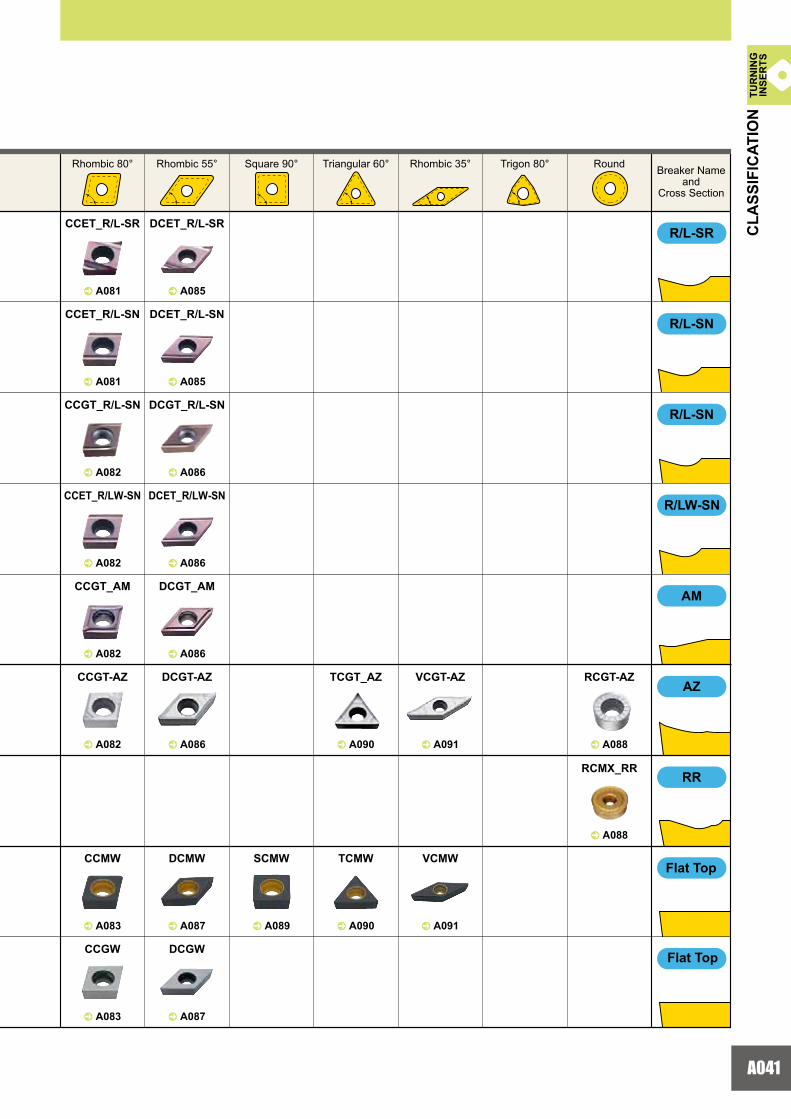
A041
^ A081 ^ A085
CCET_R/L-SR DCET_R/L-SR
^ A081 ^ A085
CCET_R/L-SN DCET_R/L-SN
^ A082 ^ A086
CCGT_R/L-SN DCGT_R/L-SN
^ A082 ^ A086
CCET_R/LW-SN DCET_R/LW-SN
^ A091
VCGT-AZ
^ A082 ^ A086
CCGT_AM DCGT_AM
^ A082 ^ A086
CCGT-AZ DCGT-AZ
^ A090
TCGT_AZ
^ A088
RCMX_RR
^ A083 ^ A087 ^ A090
CCMW DCMW TCMW
^ A091
VCMW
^ A089
SCMW
^ A083 ^ A087
CCGW DCGW
R/L-SN
R/LW-SN
AZ
AM
R/L-SR
R/L-SN
^ A088
RCGT-AZ
RR
TUR
NIN
GIN
SER
TS
Breaker Nameand
Cross Section
Rhombic 80° Rhombic 55° Square 90° Triangular 60° Rhombic 35° Trigon 80° Round
CLA
SSIF
ICAT
ION
Flat Top
Flat Top
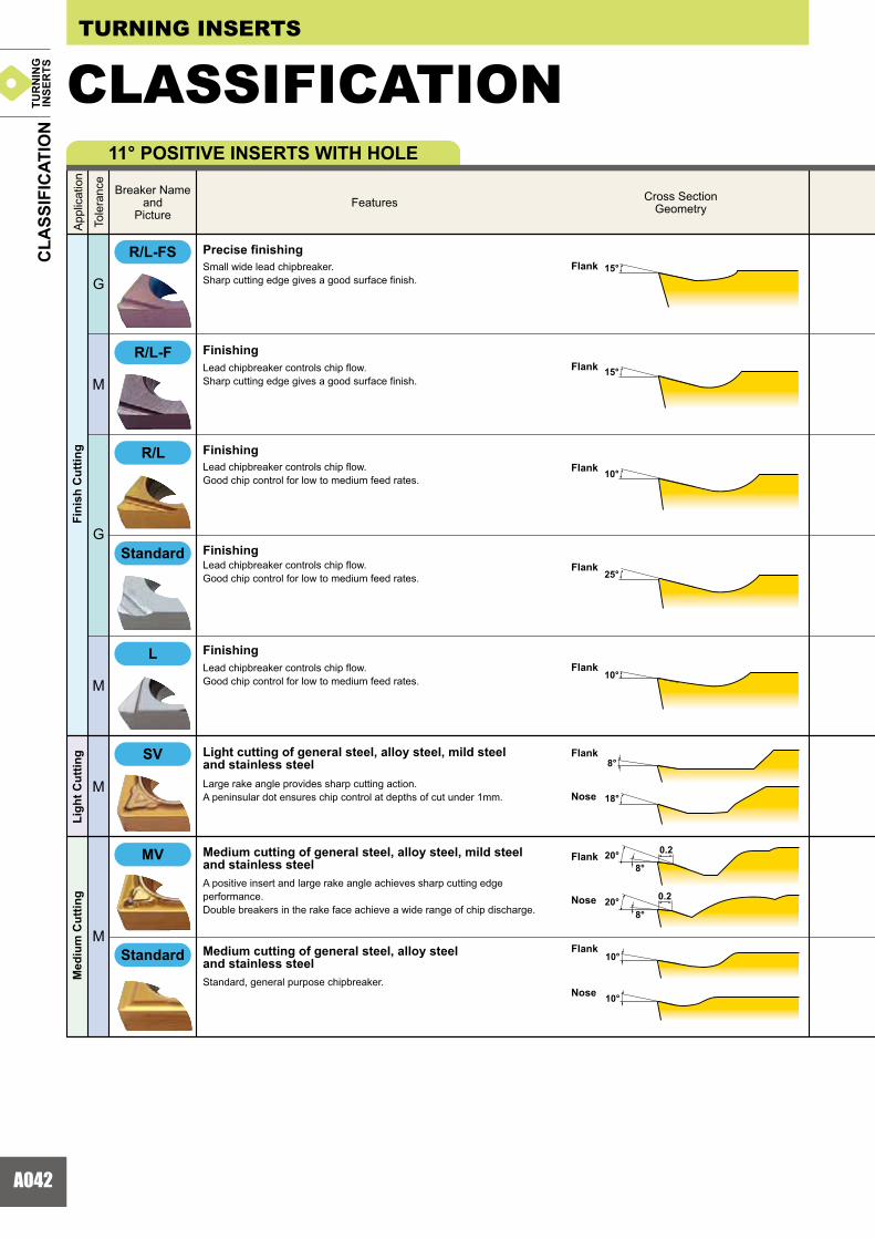
A042
15°
15°
10°
25°
10°
18°
8°
0.220°8°
0.220°8°
10°
10°
M
G
G
M
M
M
L
SV
MV
R/L
R/L-FS
R/L-F
Small wide lead chipbreaker.Sharp cutting edge gives a good surface finish.
Precise finishing
Lead chipbreaker controls chip flow.Sharp cutting edge gives a good surface finish.
Finishing
Lead chipbreaker controls chip flow.Good chip control for low to medium feed rates.
Finishing
Lead chipbreaker controls chip flow.Good chip control for low to medium feed rates.
Finishing
Lead chipbreaker controls chip flow.Good chip control for low to medium feed rates.
Finishing
Large rake angle provides sharp cutting action.A peninsular dot ensures chip control at depths of cut under 1mm.
Light cutting of general steel, alloy steel, mild steel and stainless steel
A positive insert and large rake angle achieves sharp cutting edge performance.Double breakers in the rake face achieve a wide range of chip discharge.
Medium cutting of general steel, alloy steel, mild steel and stainless steel
Standard, general purpose chipbreaker.
Medium cutting of general steel, alloy steel and stainless steel
TUR
NIN
GIN
SER
TS
Breaker Nameand
PictureFeatures Cross Section
Geometry
CLA
SSIF
ICAT
ION
App
licat
ion
Tole
ranc
e
TURNING INSERTS
CLASSIFICATION11° POSITIVE INSERTS WITH HOLE
Flank
Nose
Flank
Nose
Flank
Nose
Flank
Flank
Flank
Flank
Flank
Fini
sh C
uttin
gLi
ght C
uttin
gM
ediu
m C
uttin
g
Standard
Standard

A043
^ A095
TPGH_R/L-FS
^ A098
WPGT_R/L-FS
^ A093
CPMH_R/L-F
^ A095
TPGX_R/L
^ A093
CPGT
^ A098
WPGT
^ A096
TPMX_L
^ A093
CPMH_SV
^ A096
TPMH_SV
^ A098
WPMT_MV
^ A096
TPMH_MV
^ A093
CPMH_MV
^ A093 ^ A096
CPMX TPMX
^ A094
SPMT
R/L
MV
SV
L
R/L-FS
R/L-F
TUR
NIN
GIN
SER
TS
Breaker Nameand
Cross Section
Rhombic 80° Rhombic 55° Square 90° Triangular 60° Rhombic 35° Trigon 80° Round
CLA
SSIF
ICAT
ION
Standard
Standard
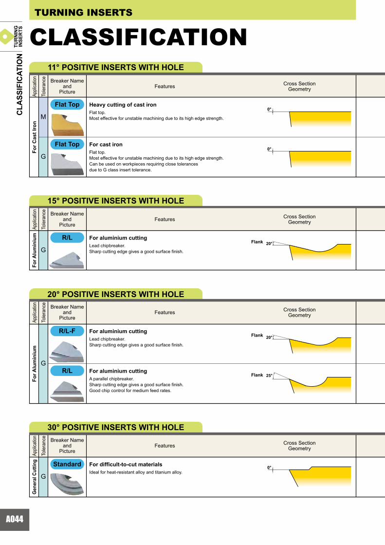
A044
0°
0°
0°
20°
20°
25°
R/L
R/L-F
R/L
G
G
M
G
G
TUR
NIN
GIN
SER
TS
Breaker Nameand
PictureFeatures Cross Section
Geometry
CLA
SSIF
ICAT
ION
Appli
catio
n
Tole
ranc
e
TURNING INSERTS
CLASSIFICATION11° POSITIVE INSERTS WITH HOLE
Breaker Nameand
PictureFeatures Cross Section
Geometry
Appli
catio
n
Tole
ranc
e
15° POSITIVE INSERTS WITH HOLE
Breaker Nameand
PictureFeatures Cross Section
Geometry
Appli
catio
n
Tole
ranc
e
20° POSITIVE INSERTS WITH HOLE
Breaker Nameand
PictureFeatures Cross Section
Geometry
Appli
catio
n
Tole
ranc
e
30° POSITIVE INSERTS WITH HOLE
Flat Top
Flat Top
Standard
Flank
Flank
Flank
Flat top.Most effective for unstable machining due to its high edge strength.
Heavy cutting of cast iron
Flat top.Most effective for unstable machining due to its high edge strength. Can be used on workpieces requiring close tolerances due to G class insert tolerance.
For cast iron
Lead chipbreaker.Sharp cutting edge gives a good surface finish.
For aluminium cutting
Lead chipbreaker.Sharp cutting edge gives a good surface finish.
For aluminium cutting
A parallel chipbreaker.Sharp cutting edge gives a good surface finish.Good chip control for medium feed rates.
For aluminium cutting
Ideal for heat-resistant alloy and titanium alloy.For difficult-to-cut materials
For C
ast I
ron
For A
lum
iniu
mFo
r Alu
min
ium
Gen
eral
Cut
ting
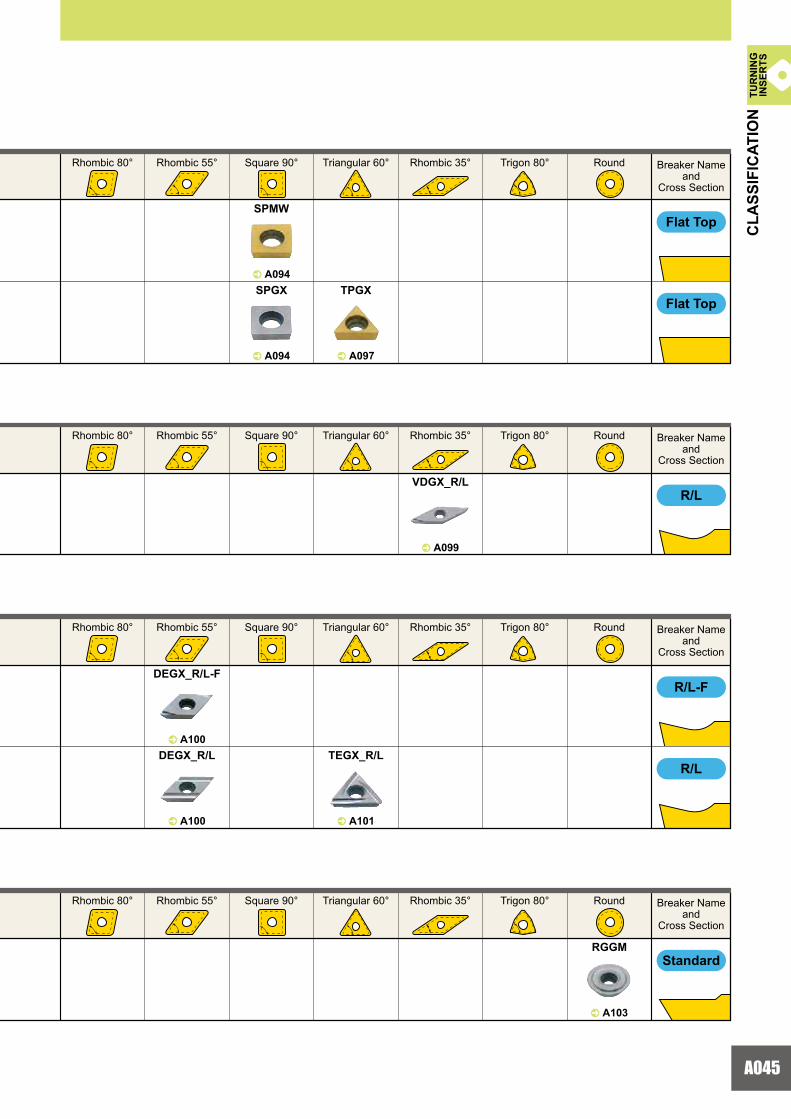
A045
^ A099
VDGX_R/L
^ A103
RGGM
^ A100
DEGX_R/L-F
^ A094
SPMW
^ A094
SPGX
^ A097
TPGX
^ A100
DEGX_R/L
^ A101
TEGX_R/L
R/L
R/L-F
R/L TU
RN
ING
INSE
RTS
CLA
SSIF
ICAT
ION
Flat Top
Breaker Nameand
Cross Section
Rhombic 80° Rhombic 55° Square 90° Triangular 60° Rhombic 35° Trigon 80° Round
Breaker Nameand
Cross Section
Rhombic 80° Rhombic 55° Square 90° Triangular 60° Rhombic 35° Trigon 80° Round
Breaker Nameand
Cross Section
Rhombic 80° Rhombic 55° Square 90° Triangular 60° Rhombic 35° Trigon 80° Round
Breaker Nameand
Cross Section
Rhombic 80° Rhombic 55° Square 90° Triangular 60° Rhombic 35° Trigon 80° Round
Flat Top
Standard

A046
0°
0°
0°
0°
0°
0°
0.312°
15°
7°
7°
R/L-M1/2
R/L
G
M
M
G
G
M
M
80
NEGATIVE INSERTS WITHOUT HOLE
11° POSITIVE INSERTS WITHOUT HOLE
TUR
NIN
GIN
SER
TSC
LASS
IFIC
ATIO
NTURNING INSERTS
CLASSIFICATION
Flank
Med
ium
to
Hea
vy C
uttin
gLi
ght t
o M
ediu
m C
uttin
g
Flat Top
Flat Top
Flat Top
Standard
Flat Top
Flank
Flank
Nose
Flank
Nose
Single sided chipbreaker.Can be used for copying.An angled chipbreaker for controlling chip flow.
Medium cutting of general steel
Double sided flat insert.Most effective for unstable machining due to high edge strength and stable insert clamping.
Heavy cutting of cast iron
Double sided flat insert.Most effective for unstable machining due to high edge strength and stable insert clamping.Can be used on workpieces requiring close tolerances due to G class insert tolerance.
For cast iron
A parallel chipbreaker.Good chip control for low to medium feed rates.
Finishing
Standard, general purpose chipbreaker.
Light to medium cutting of general steel, alloy steel and stainless steel
Flat top.Most effective for unstable machining due to high edge strength and stable insert clamping.
Heavy cutting of cast iron
Flat top.Most effective for unstable machining due to high edge strength and stable insert clamping.Can be used on workpieces requiring close tolerances due to G class insert tolerance.
For cast iron
Breaker Nameand
PictureFeatures Cross Section
Geometry
Appli
catio
n
Tole
ranc
e
Breaker Nameand
PictureFeatures Cross Section
Geometry
Appli
catio
n
Tole
ranc
e
Large chip pocket for excellent chip evacuation.Double breakers in the rake face achieves a wide range of chip breaking.
Light to medium cutting of general steel, alloy steel and stainless steel
For C
ast I
ron
For C
ast I
ron
Fini
sh C
uttin
g

A047
^ A075
KNUX_R/L-M1/2
^ A057,A102
RNGJ,RDGH
^ A108
RTG
^ A073
SNMN
^ A073
SNGN^ A074
TNMN
^ A074
TNGN
^ A104
SPMR
^ A104
SPMN
^ A105
SPGN
^ A106
TPGR_R/L
^ A107
TPMR
^ A106,A107
TPMN
^ A107
TPGN
R/L
R/L-M1/2
G
^ A104 ^ A106
SPMR-80 TPMR-8080
TUR
NIN
GIN
SER
TSC
LASS
IFIC
ATIO
N
Flat Top
Flat Top
Flat Top
Standard
Flat Top
ROTARY Holder
TL Type
Breaker Nameand
Cross Section
Square 90° Triangular 60° Parallelogram 55°
Square 90° Triangular 60° Round
Tool Holder Type Inserts
Appli
catio
nSp
ecia
lTo
leran
ce
SPECIAL PURPOSE INSERTS
Breaker Nameand
Cross Section
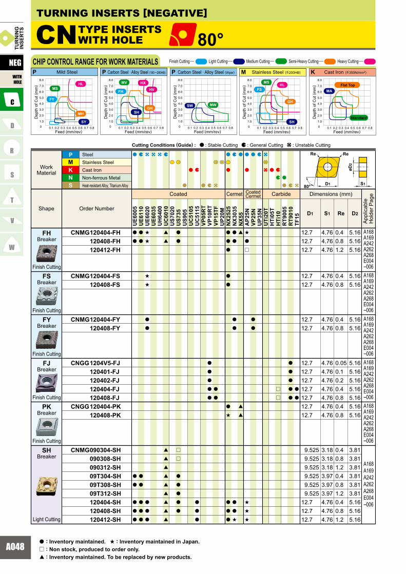
A048
CNMG 120404-FH 120408-FH 120412-FH
CNMG 120404-FS 120408-FS
CNMG 120404-FY 120408-FY
CNGG 1204V5-FJ 120401-FJ 120402-FJ 120404-FJ 120408-FJCNGG 120404-PK 120408-PK
CNMG 090304-SH 090308-SH 090312-SH 09T304-SH 09T308-SH 09T312-SH 120404-SH 120408-SH 120412-SH
A168A169A242A262A268E004�006
CN 80°
KNS
MP
ReD1 S1 D2
a
a
a
a
a
a
a
a
a
a
a
a
a
a
s
s
s
s
a
a
a
a
a
[
[
[
[
[
[
[
[
[
[
[
a
a
r
r
a
a
a
a
a
a
a
a
a
a
a
a
a
a
a
a
a
a
a
a
a
s
a
a
a
a
a
a
a
a
a
s
[
[
[
s
a
r
s
s
s
a
a
r
r
a
a
a
a
a
a
a
UE6
005
UE6
110
UE6
020
UE6
035
UH
6400
UC
6010
US7
020
US7
35U
S905
UC
5105
UC
5115
VP05
RT
VP10
RT
VP15
TFU
P20M
NX2
525
NX3
035
NX5
5A
P25N
VP25
NU
P35N
UTi
20T
HTi
05T
HTi
10R
T900
5R
T901
0TF
15
P KMP P
4.76 0.4 5.164.76 0.8 5.164.76 1.2 5.16
12.7
12.712.7
4.76 0.4 5.164.76 0.8 5.16
4.76 0.054.76 0.14.76 0.24.76 0.4 5.16
5.165.165.16
4.76 0.8 5.164.76 0.4 5.164.76 0.8 5.16
3.18 0.4 3.813.18 0.8 3.813.18 1.2 3.813.97 0.4 3.813.97 0.8 3.813.97 1.2 3.814.76 0.4 5.164.76 0.8 5.164.76 1.2 5.16
12.712.712.7
9.5259.5259.525
9.5259.525
9.525
12.7
12.7
12.712.712.7
12.712.712.7
12.7
4.76 0.4 5.164.76 0.8 5.16
12.712.7
A168A169A242A262A268E004�006A168A169A242A262A268E004�006A168A169A242A262A268E004�006A168A169A242A262A268E004�006
A168A169A242A262A268E004�006
0 0.1 0.2 0.3 0.4 0.5 0.6 0.7 0.8
1.0
2.0
3.0
4.0
5.0
6.0
7.0
8.0
0 0.1 0.2 0.3 0.4 0.5 0.6 0.7 0.8
1.0
2.0
3.0
4.0
5.0
6.0
7.0
8.0
0 0.1 0.2 0.3 0.4 0.5 0.6 0.7 0.8
1.0
2.0
3.0
4.0
5.0
6.0
7.0
8.0
0 0.1 0.2 0.3 0.4 0.5 0.6 0.7 0.8
1.0
2.0
3.0
4.0
5.0
6.0
7.0
8.0
SH
FH
GH
HX
HV
MV
SH
GH
HLMS
FS
0 0.1 0.2 0.3 0.4 0.5 0.6 0.7 0.8
1.0
2.0
3.0
4.0
5.0
6.0
7.0
8.0
SW MW
80° D1 S1
øD2
ReRe
MA
FY
SY
MH
HLMS
TURNING INSERTS [NEGATIVE]
TYPE INSERTS WITH HOLE
Coated Cermet CoatedCermet Carbide
Order Number
SteelStainless SteelCast Iron Non-ferrous Metal Heat-resistant Alloy, Titanium Alloy
Dimensions (mm)
App
licab
leH
olde
r Pag
e
Cutting Conditions (Guide) : : Stable Cutting : General Cutting : Unstable Cutting
NEG
WITHHOLE
TUR
NIN
GIN
SER
TS
Finish Cutting Light Cutting Medium Cutting Semi-Heavy Cutting Heavy CuttingCHIP CONTROL RANGE FOR WORK MATERIALSMild Steel Carbon Steel · Alloy Steel (180 �280HB) Stainless Steel (<200HB) Cast Iron (<350N/mm2)
Dep
th o
f Cut
( mm
)
Feed (mm/rev)
Dep
th o
f Cut
( mm
)
Feed (mm/rev)
Dep
th o
f Cut
( mm
)
Feed (mm/rev)
Standard
Flat Top
Dep
th o
f Cut
( mm
)
Feed (mm/rev)
Carbon Steel · Alloy Steel (Wiper)
Dep
th o
f Cut
( mm
)
Feed (mm/rev)
: Inventory maintained.a : Inventory maintained in Japan.s
: Non stock, produced to order only.r
: Inventory maintained. To be replaced by new products.[
Breaker
Finish Cutting
Breaker
Finish Cutting
Breaker
Breaker
Breaker
Breaker
Finish Cutting
Finish Cutting
Finish Cutting
Light Cutting
Shape
WorkMaterial
FY
FH
SH
PK
FJ
FS

A049
A002A018A010
CNMG 120404-SA 120408-SA 120412-SA 160608-SA 160612-SACNMG 120404-SW 120408-SW
CNMG 120404-SY 120408-SY
CNMG 120404-MV 120408-MV 120412-MV 120416-MV
CNMG 120404-MA 120408-MA 120412-MA 120416-MA 160608-MA 160612-MA 160616-MA 190612-MA 190616-MACNMG 120404-MH 120408-MH 120412-MH 120416-MH 160608-MH 160616-MH 160612-MH 190612-MH 190616-MHCNMG 090304 090308 09T304 09T308 120404 120408 120412 120416
A168A169A242A262A268E004�006A168A169A242A262A268E004�006A168A169A242A262A268E004�006A168A169A242A262A268E004�006
A168A169A242A262A268E004�006
A168A169A242A262A268E004�006
A168A169A242A262A268E004�006
KNS
MP
ReD1 S1 D2
UE6
005
UE6
110
UE6
020
UE6
035
UH
6400
UC
6010
US7
020
US7
35U
S905
UC
5105
UC
5115
VP05
RT
VP10
RT
VP15
TFU
P20M
NX2
525
NX3
035
NX5
5A
P25N
VP25
NU
P35N
UTi
20T
HTi
05T
HTi
10R
T900
5R
T901
0TF
15
a
a
a
a
a
a
a
a
a
a
a
a
a
a
a
a
a
a
a
a
a
a
a
a
a
a
a
a
a
a
a
a
a
a
a
a
a
a
a
a
a
a
a
a
a
a
a
a
a
a
a
a
a
a
a
a
s
s
a
a
a
a
a
a
a
a
a
a
a
a
a
s
a
s
a
a
a
a
a
a
a
a
a
s
a
a
a
a
a
a
a
s
a
a
a
a
a
s
s
s
s
s
a
a
a
a
a
a
r
a
a
r
[
[
[
[
[
[
[
[
[
[
[
[
[
[
[
[
[
[
s
s
[
[
[
[
[
[
a
a
a
a
a
a
r
a
a
r
r
a
a
a
a
a
a
a
a
a
a
a
a
a
a
a
r
a
a
a
a
a
a
a
a
a
a
a
a
a
s
a
r
a
a
a
a
a
a
a
r
a
a
a
a
s
a
a
a
s
a
a
s
s
a
a
a
a
a
a
a
s
a
a
a
a
a
s
a
a
a
a
a
a
a
a
a
a
a
a
a
[
[
[
[
a
a
[
[
[
[
[
a
a
a
a
a
r
4.76 0.4 5.164.76 0.8 5.164.76 1.2 5.16
15.875 6.35 0.8 6.3515.875 6.35 1.2 6.35
12.712.712.7
4.76 0.4 5.164.76 0.8 5.16
12.712.7
4.76 0.4 5.164.76 0.8 5.16
12.712.7
4.76 0.4 5.164.76 0.8 5.164.76 1.2 5.164.76 1.6 5.16
4.76 0.4 5.164.76 0.8 5.164.76 1.2 5.164.76 1.6 5.166.35 0.8 6.356.35 1.2 6.356.35 1.6 6.356.35 1.2 7.936.35 1.6 7.93
12.712.712.7
15.87515.87515.87519.05
12.7
19.05
12.712.7
12.712.7
3.18 0.4 3.813.18 0.8 3.813.97 0.4 3.813.97 0.8 3.814.76 0.4 5.164.76 0.8 5.164.76 1.2 5.164.76 1.6 5.1612.7
12.712.712.7
9.5259.5259.5259.525
4.76 0.4 5.164.76 0.8 5.164.76 1.2 5.164.76 1.6 5.16
6.35 1.2 6.356.35 1.2 7.936.35 1.6 7.93
12.7
15.8756.35 1.6 6.3515.8756.35 0.8 6.3515.875
19.0519.05
12.712.7
12.7
80° D1 S1
øD2
ReRe
Coated Cermet CoatedCermet Carbide
Order NumberShape
WorkMaterial
SteelStainless Steel Cast IronNon-ferrous MetalHeat-resistant Alloy, Titanium Alloy
Dimensions (mm)
App
licab
leH
olde
r Pag
e
Cutting Conditions (Guide) : : Stable Cutting : General Cutting : Unstable Cutting TUR
NIN
GIN
SER
TS
NEG
WITHHOLE
*Please refer to page A016 before using the SW breaker (wiper insert).
Breaker
Light Cutting
Light Cutting
Breaker
Light Cutting(Wiper)
Breaker
Medium Cutting
Medium Cutting
Breaker
Breaker
SA
SY
SW*
MA
MV
Medium Cutting
StandardBreaker
Breaker
Medium Cutting
MH
IDENTIFICATIONGRADESCHIP BREAKERS
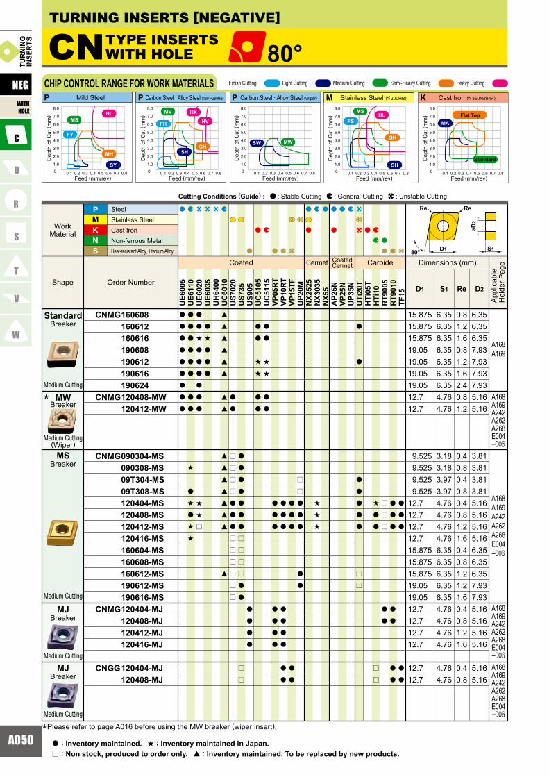
A050
CNMG 160608 160612 160616 190608 190612 190616 190624CNMG 120408-MW 120412-MW
CNMG 090304-MS 090308-MS 09T304-MS 09T308-MS 120404-MS 120408-MS 120412-MS 120416-MS 160604-MS 160608-MS 160612-MS 190612-MS 190616-MSCNMG 120404-MJ 120408-MJ 120412-MJ 120416-MJ
CNGG 120404-MJ 120408-MJ
A168A169
A168A169A242A262A268E004�006
A168A169A242A262A268E004�006
A168A169A242A262A268E004�006A168A169A242A262A268E004�006
KNS
MP
ReD1 S1 D2
a
a
a
a
a
a
a
a
a
a
a
a
a
a
a
a
a
s
a
s
a
s
s
a
a
s
a
a
a
a
a
a
s
s
r
r
a
s
a
a
a
[
[
[
[
[
[
[
[
[
[
[
[
[
[
[
[
a
a
r
r
r
r
a
a
a
r
r
r
r
r
r
a
a
a
a
a
a
a
r
r
r
r
a
a
r
r
a
a
a
a
a
a
s
s
a
a
a
a
s
s
a
a
a
a
a
a
a
a
a
a
a
a
a
a
a
a
a
a
a
a
a
a
a
r
r
a
a
a
a
a
s
s
s
a
a
a
a
a
a
a
r
r
s
a
a
r
r
r
r
r
a
a
a
a
a
a
a
a
a
a
a
a
a
a
UE6
005
UE6
110
UE6
020
UE6
035
UH
6400
UC
6010
US7
020
US7
35U
S905
UC
5105
UC
5115
VP05
RT
VP10
RT
VP15
TFU
P20M
NX2
525
NX3
035
NX5
5A
P25N
VP25
NU
P35N
UTi
20T
HTi
05T
HTi
10R
T900
5R
T901
0TF
15
P KMP P
4.76 0.8 5.164.76 1.2 5.16
6.35 0.8 6.356.35 1.2 6.356.35 1.6 6.356.35 0.8 7.936.35 1.2 7.936.35 1.6 7.93
4.76 0.4 5.164.76 0.8 5.16
3.18 0.4 3.813.18 0.8 3.813.97 0.4 3.813.97 0.8 3.814.76 0.4 5.164.76 0.8 5.164.76 1.2 5.164.76 1.6 5.166.35 0.4 6.356.35 0.8 6.356.35 1.2 6.356.35 1.2 7.936.35 1.6 7.93
12.7
15.87515.87515.875
19.0519.05
12.712.7
15.87515.87515.875
12.79.5259.5259.5259.525
12.74.76 1.2 5.1612.74.76 1.6 5.1612.7
12.7
19.056.35 2.4 7.9319.05
19.0519.05
12.712.7
4.76 0.4 5.164.76 0.8 5.1612.7
12.7
CN 80°
0 0.1 0.2 0.3 0.4 0.5 0.6 0.7 0.8
1.0
2.0
3.0
4.0
5.0
6.0
7.0
8.0
0 0.1 0.2 0.3 0.4 0.5 0.6 0.7 0.8
1.0
2.0
3.0
4.0
5.0
6.0
7.0
8.0
0 0.1 0.2 0.3 0.4 0.5 0.6 0.7 0.8
1.0
2.0
3.0
4.0
5.0
6.0
7.0
8.0
0 0.1 0.2 0.3 0.4 0.5 0.6 0.7 0.8
1.0
2.0
3.0
4.0
5.0
6.0
7.0
8.0
SH
FH
GH
HX
HV
MV
SH
GH
HLMS
FS
0 0.1 0.2 0.3 0.4 0.5 0.6 0.7 0.8
1.0
2.0
3.0
4.0
5.0
6.0
7.0
8.0
SW MW
MA
80° D1 S1
øD2
ReRe
FY
SY
MH
HLMS
Coated Cermet CoatedCermet Carbide
Order Number Shape
Work Material
SteelStainless SteelCast Iron Non-ferrous Metal Heat-resistant Alloy, Titanium Alloy
Dimensions (mm)
App
licab
leH
olde
r Pag
e
Cutting Conditions (Guide) : : Stable Cutting : General Cutting : Unstable Cutting
NEG
WITHHOLE
TUR
NIN
GIN
SER
TS
Finish Cutting Light Cutting Medium Cutting Semi-Heavy Cutting Heavy CuttingCHIP CONTROL RANGE FOR WORK MATERIALSMild Steel Carbon Steel · Alloy Steel (180 �280HB) Stainless Steel (<200HB) Cast Iron (<350N/mm2)
Dep
th o
f Cut
( mm
)
Feed (mm/rev)
Dep
th o
f Cut
( mm
)
Feed (mm/rev)
Dep
th o
f Cut
( mm
)
Feed (mm/rev)
Standard
Flat Top
Dep
th o
f Cut
( mm
)
Feed (mm/rev)
Carbon Steel · Alloy Steel (Wiper)
Dep
th o
f Cut
( mm
)
Feed (mm/rev)
Medium Cutting
Medium Cutting
Medium Cutting
StandardBreaker
Medium Cutting(Wiper)
Breaker
Breaker
Breaker
MW
MS
MJ
*
*Please refer to page A016 before using the MW breaker (wiper insert).
Medium Cutting
BreakerMJ
TURNING INSERTS [NEGATIVE]
TYPE INSERTSWITH HOLE
: Non stock, produced to order only.r
: Inventory maintained.a : Inventory maintained in Japan.s
: Inventory maintained. To be replaced by new products.[

A051
A002A018A010
CNMG 120408-GH 120412-GH 120416-GH 160612-GH 160616-GH 190612-GH 190616-GHCNMG 120408-GJ 120412-GJ 120416-GJ 160612-GJ 190612-GJ 190616-GJCNMM 120408-HL 120412-HL 120416-HL 160612-HL 160616-HL 190612-HL 190616-HL 190624-HLCNMM 160612-HM 160616-HM 190612-HM 190616-HM 190624-HM 250924-HMCNMM 160612-HX 160616-HX 190612-HX 190616-HX 190624-HX 250924-HXCNMM 190616-HV 190624-HV 250924-HV
CNMM 190616-HCS 190624-HCS 250924-HCS
A168A169A242A262A268E004�006
A168A169A242A262A268E004�006
A168A169A242A262A268E004�006
A168A169
A168A169
A168A169
A168A169
KNS
MP
ReD1 S1 D2
UE6
005
UE6
110
UE6
020
UE6
035
UH
6400
UC
6010
US7
020
US7
35U
S905
UC
5105
UC
5115
VP05
RT
VP10
RT
VP15
TFU
P20M
NX2
525
NX3
035
NX5
5A
P25N
VP25
NU
P35N
UTi
20T
HTi
05T
HTi
10R
T900
5R
T901
0TF
15
a
a
a
a
r
a
a
a
a
a
a
a
a
a
a
a
a
a
a
a
a
a
a
a
a
a
a
a
a
a
a
a
a
a
a
a
a
a
a
a
a
a
a
a
a
a
a
a
a
a
a
a
a
a
a
a
a
a
a
a
a
a
a
a
a
a
a
a
a
a
a
a
[
[ a
a
a
a
a
a
a
a
a
a
a
a
a
a
a
a
a
a
a
[
[
[
[
[
[
a
a
s
s
s
a
a
a
a
a
a
a
a
a
a
a
a
a
a
a
a
a
a
a
a
s
s
a
a
a
a
a
s
s
a
a
a
a
a
a
a
a
a
a
a
a
a
a
a
a
a
a
4.76 0.8 5.164.76 1.2 5.16
6.35 1.2 6.35
6.35 1.2 7.936.35 1.6 7.934.76 0.8 5.164.76 1.2 5.164.76 1.6 5.16
6.35
6.356.35
7.937.93
7.937.937.939.12
6.35 1.26.35 1.26.35 1.6
6.35 1.26.35 1.66.35 1.26.35 1.66.35 2.49.52 2.425.40
19.0519.0519.0515.87515.875
19.0519.0515.87512.712.712.719.0519.05
15.8756.35 1.6 6.3515.875
12.74.76 1.6 5.1612.7
12.7
15.875
19.0519.0519.0525.40
12.712.7
15.87515.87519.0519.05
4.76 0.8 5.164.76 1.2 5.16
6.35 1.2 6.3512.7 4.76 1.6 5.16
19.05 6.35 2.4 7.93
15.875 6.35 1.6 6.35
19.05 6.35 1.6 7.9319.05 6.35 2.4 7.93
6.35 1.6 6.356.35 1.2 7.936.35 1.6 7.93
6.35 1.2 6.35
6.35 1.2 7.936.35 1.6 7.936.35 2.4 7.939.52 2.4 9.12
9.52 2.4 9.1225.4
6.35 1.6 7.936.35 2.4 7.939.52 2.4 9.1225.4
19.0519.05
80° D1 S1
øD2
ReRe
Heavy Cutting
Breaker
Heavy Cutting
Breaker
HCS
HV
Semi-HeavyCutting
Semi-HeavyCutting
Heavy Cutting
Breaker
Breaker
Breaker
Breaker
GH
GJ
HL
HM
Coated Cermet CoatedCermet Carbide
Order NumberShape
WorkMaterial
SteelStainless Steel Cast IronNon-ferrous MetalHeat-resistant Alloy, Titanium Alloy
Dimensions (mm)
App
licab
leH
olde
r Pag
e
Cutting Conditions (Guide) : : Stable Cutting : General Cutting : Unstable Cutting TUR
NIN
GIN
SER
TS
NEG
WITHHOLE
BreakerHX
IDENTIFICATIONGRADESCHIP BREAKERS
Heavy Cutting
Heavy Cutting

A052
CNMA 120404 120408 120412 120416 160612 160616 190612 190616 190624
A168A169A242A262A268E004�006
CN 80°
KNS
MP
ReD1 S1 D2
a
a
a
a
a
a
a
a
a
a
a
a
a
a
a
a
a
a
a
a
a
a
a
a
a
s
r
r
s
s
s
a
a
a
s
UE6
005
UE6
110
UE6
020
UE6
035
UH
6400
UC
6010
US7
020
US7
35U
S905
UC
5105
UC
5115
VP05
RT
VP10
RT
VP15
TFU
P20M
NX2
525
NX3
035
NX5
5A
P25N
VP25
NU
P35N
UTi
20T
HTi
05T
HTi
10R
T900
5R
T901
0TF
15
P KMP P
4.76 0.4 5.164.76 0.8 5.164.76 1.2 5.164.76 1.6 5.166.35 1.2 6.356.35 1.6 6.356.35 1.2 7.93
6.35 2.4 7.93
12.712.712.712.715.87515.87519.05
19.056.35 1.6 7.9319.05
0 0.1 0.2 0.3 0.4 0.5 0.6 0.7 0.8
1.0
2.0
3.0
4.0
5.0
6.0
7.0
8.0
0 0.1 0.2 0.3 0.4 0.5 0.6 0.7 0.8
1.0
2.0
3.0
4.0
5.0
6.0
7.0
8.0
0 0.1 0.2 0.3 0.4 0.5 0.6 0.7 0.8
1.0
2.0
3.0
4.0
5.0
6.0
7.0
8.0
0 0.1 0.2 0.3 0.4 0.5 0.6 0.7 0.8
1.0
2.0
3.0
4.0
5.0
6.0
7.0
8.0
SH
FH
GH
HX
HV
MV
SH
GH
HLMS
FS
0 0.1 0.2 0.3 0.4 0.5 0.6 0.7 0.8
1.0
2.0
3.0
4.0
5.0
6.0
7.0
8.0
SW MW
MA
80° D1 S1
øD2
ReRe
FY
SY
MH
HLMS
TURNING INSERTS [NEGATIVE]
TYPE INSERTS WITH HOLE
Coated Cermet CoatedCermet Carbide
Order Number Shape
Work Material
SteelStainless SteelCast Iron Non-ferrous Metal Heat-resistant Alloy, Titanium Alloy
Dimensions (mm)
App
licab
leH
olde
r Pag
e
Cutting Conditions (Guide) : : Stable Cutting : General Cutting : Unstable Cutting
NEG
WITHHOLE
TUR
NIN
GIN
SER
TS
Finish Cutting Light Cutting Medium Cutting Semi-Heavy Cutting Heavy CuttingCHIP CONTROL RANGE FOR WORK MATERIALSMild Steel Carbon Steel · Alloy Steel (180 �280HB) Stainless Steel (<200HB) Cast Iron (<350N/mm2)
Dep
th o
f Cut
( mm
)
Feed (mm/rev)
Dep
th o
f Cut
( mm
)
Feed (mm/rev)
Dep
th o
f Cut
( mm
)
Feed (mm/rev)
Standard
Flat Top
Dep
th o
f Cut
( mm
)
Feed (mm/rev)
Carbon Steel · Alloy Steel (Wiper)
Dep
th o
f Cut
( mm
)
Feed (mm/rev)
Flat Top
: Non stock, produced to order only.r
: Inventory maintained.a : Inventory maintained in Japan.s
: Inventory maintained. To be replaced by new products.[

A002A018A010
A053
DNMG 150404-FH 150408-FH 150604-FH 150608-FH
DNMG 150404-FS 150408-FS 150604-FS 150608-FS
DNMG 150404-FY 150408-FY 150604-FY 150608-FY
DNGG 150404-FJ 150408-FJ
DNGG 150404-PK 150408-PK 150604-PK 150608-PK
DNMG 110404-SH 110408-SH 150404-SH 150408-SH 150412-SH 150604-SH 150608-SH 150612-SH
A170A171A242A262�264A267A268E007�009A170A171A242A262�264A267A268E007�009A170A171A242A262�264A267A268E007�009A170A171A242A262�264A267A268E007�009
ReD1 S1 D2
4.76 0.4 5.164.76 0.8 5.16
6.35 0.4 5.166.35 0.8 5.16
4.76 0.4 5.164.76 0.8 5.16
4.76 0.4 5.164.76 0.8 5.16
4.76 0.8 3.814.76 0.4 3.81
4.76 0.4 5.164.76 0.8 5.164.76 1.2 5.16
12.712.7
6.35 0.4 5.1612.76.35 0.8 5.1612.76.35 1.2 5.1612.7
12.79.5259.525
12.712.7
6.35 0.4 5.166.35 0.8 5.16
12.712.7
12.712.7
12.712.7
4.76 0.4 5.164.76 0.8 5.16
12.712.7
4.76 0.4 5.164.76 0.8 5.16
12.712.7
6.35 0.4 5.1612.76.35 0.8 5.1612.7
12.76.35 0.4 5.1612.76.35 0.8 5.1612.7
12.7
A170A171A242A262�264A267A268E007�009
A170A171A242A262�264A267A268E007�009
DN 55°
KNS
MP
a
a
a
a
a
a
a
a
a
a
a
a
a
a
a
a
a
a
a
a
a
a
a
a
s
s
s
s
a
a
a
a
a
a
s
[
[
[
[
[
[
[
[
[
[
[
[
a
a
a
a
a
a
a
a
a
a
a
a
a
a
a
a
a
a
a
a
a
a
a
a
a
a
a
a
a
a
a
a
a
a
s
a
a
a
a
a
a
a
a
a
a
a
a
a
s
a
a
s
s
s
s
s
s
a
a
a
a
r
r
a
a
a
a
UE6
005
UE6
110
UE6
020
UE6
035
UH
6400
UC
6010
US7
020
US7
35U
S905
UC
5105
UC
5115
VP05
RT
VP10
RT
VP15
TFU
P20M
NX2
525
NX3
035
NX5
5A
P25N
VP25
NU
P35N
UTi
20T
HTi
05T
HTi
10R
T900
5R
T901
0TF
15
P KMP P
D1
øD2
S155°
Re
0 0.1 0.2 0.3 0.4 0.5 0.6 0.7 0.8
1.0
2.0
3.0
4.0
5.0
6.0
7.0
8.0
SW MW
0 0.1 0.2 0.3 0.4 0.5 0.6 0.7 0.8
1.0
2.0
3.0
4.0
5.0
6.0
7.0
8.0
0 0.1 0.2 0.3 0.4 0.5 0.6 0.7 0.8
1.0
2.0
3.0
4.0
5.0
6.0
7.0
8.0
SH
FH
GH
HLMV
0 0.1 0.2 0.3 0.4 0.5 0.6 0.7 0.8
1.0
2.0
3.0
4.0
5.0
6.0
7.0
8.0
0 0.1 0.2 0.3 0.4 0.5 0.6 0.7 0.8
1.0
2.0
3.0
4.0
5.0
6.0
7.0
8.0
FS
SH
GH
HLMS
MA
FY
SY
MH
HLMS
Finish Cutting
Breaker
Finish Cutting
Finish Cutting
Finish Cutting
Finish Cutting
Light Cutting
Breaker
Breaker
Breaker
Breaker
Breaker
FY
FH
FS
PK
FJ
SH
IDENTIFICATIONGRADESCHIP BREAKERS
TYPE INSERTSWITH HOLE
Coated Cermet CoatedCermet Carbide
Order NumberShape
WorkMaterial
SteelStainless Steel Cast IronNon-ferrous MetalHeat-resistant Alloy, Titanium Alloy
Dimensions (mm)
App
licab
leH
olde
r Pag
e
Cutting Conditions (Guide) : : Stable Cutting : General Cutting : Unstable Cutting
TUR
NIN
GIN
SER
TS
NEG
WITHHOLE
Dep
th o
f Cut
( mm
)
Feed (mm/rev)
CHIP CONTROL RANGE FOR WORK MATERIALS
Dep
th o
f Cut
( mm
)
Feed (mm/rev)
Dep
th o
f Cut
( mm
)
Feed (mm/rev)
Dep
th o
f Cut
( mm
)
Feed (mm/rev)
Dep
th o
f Cut
( mm
)
Feed (mm/rev)
Finish Cutting Light Cutting Medium Cutting Semi-Heavy Cutting Heavy Cutting
Mild Steel Carbon Steel · Alloy Steel (180 �280HB) Stainless Steel (<200HB) Cast Iron (<350N/mm2)Carbon Steel · Alloy Steel (Wiper)
Standard
Flat Top

A054
DNMG 150404-SA 150408-SA 150412-SA 150604-SA 150608-SA 150612-SADNMX 150404-SW 150408-SW 150604-SW 150608-SW
DNMG 150404-SY 150408-SY 150604-SY 150608-SY
DNMG 150404-MV 150408-MV 150412-MV 150416-MV 150604-MV 150608-MV 150612-MV 150616-MVDNMG 110404-MA 110408-MA 110412-MA 150404-MA 150408-MA 150412-MA 150416-MA 150604-MA 150608-MA 150612-MA 150616-MA
A170A171A242A262�264A267A268E007�009
A170A242A262A264A267
A170A171A242A262�264A267A268E007�009
A170A171A242A262�264A267A268E007�009
A170A171A242A262�264A267A268E007�009
KNS
MP
ReD1 S1 D2
a
a
a
a
a
a
a
a
a
a
a
a
a
a
a
a
a
a
a
a
a
a
a
a
a
a
a
a
a
a
a
a
a
a
a
s
s
a
a
a
a
a
a
a
a
a
a
s
a
a
a
a
a
a
a
a
a
a
a
a
a
a
s
s
s
s
a
a
a
a
a
a
a
a
a
a
s
a
s
r
a
r
[
[
[
[
[
[
[
[
[
[
[
[
a
a
a
a
a
a
r
a
a
a
a
a
a
a
a
a
a
a
a
a
r
r
r
r
a
a
a
a
a
a
a
a
a
a
a
a
a
a
a
s
a
a
s
a
a
a
a
a
a
a
a
a
a
a
a
a
a
a
a
a
a
a
a
a
a
a
a
[
[
[
[
[
[
[
[
[
UE6
005
UE6
110
UE6
020
UE6
035
UH
6400
UC
6010
US7
020
US7
35U
S905
UC
5105
UC
5115
VP05
RT
VP10
RT
VP15
TFU
P20M
NX2
525
NX3
035
NX5
5A
P25N
VP25
NU
P35N
UTi
20T
HTi
05T
HTi
10R
T900
5R
T901
0TF
15
4.76 0.4 5.164.76 0.8 5.16
12.712.7
6.35 0.4 5.1612.76.35 0.8 5.1612.7
4.76 0.4 3.819.5254.76 0.8 3.819.5254.76 1.2 3.81 9.525
4.76 1.6 5.1612.7
6.35 1.6 5.1612.7
4.76 0.4 5.164.76 0.8 5.164.76 1.2 5.164.76 1.6 5.166.35 0.4 5.166.35 0.8 5.166.35 1.2 5.166.35 1.6 5.16
4.76 0.8 5.164.76 1.2 5.16
6.35 0.4 5.166.35 0.8 5.166.35 1.2 5.16
12.7
12.712.7
12.712.7
12.7
12.7
4.76 0.4 5.1612.7
12.712.7
12.712.712.712.7
4.76 0.4 5.164.76 0.8 5.166.35 0.4 5.166.35 0.8 5.1612.7
12.712.712.7
4.76 0.4 5.164.76 0.8 5.164.76 1.2 5.166.35 0.4 5.166.35 0.8 5.166.35 1.2 5.1612.7
12.7
12.712.7
12.712.7
DN 55°P KMP P
D1
øD2
S155°
Re
0 0.1 0.2 0.3 0.4 0.5 0.6 0.7 0.8
1.0
2.0
3.0
4.0
5.0
6.0
7.0
8.0
SW MW
0 0.1 0.2 0.3 0.4 0.5 0.6 0.7 0.8
1.0
2.0
3.0
4.0
5.0
6.0
7.0
8.0
0 0.1 0.2 0.3 0.4 0.5 0.6 0.7 0.8
1.0
2.0
3.0
4.0
5.0
6.0
7.0
8.0
SH
FH
GH
HLMV
0 0.1 0.2 0.3 0.4 0.5 0.6 0.7 0.8
1.0
2.0
3.0
4.0
5.0
6.0
7.0
8.0
0 0.1 0.2 0.3 0.4 0.5 0.6 0.7 0.8
1.0
2.0
3.0
4.0
5.0
6.0
7.0
8.0
FS
SH
GH
HLMS
MA
FY
SY
MH
HLMS
Light Cutting
Breaker
Breaker
Medium Cutting
Medium Cutting
Light Cutting(Wiper)
Breaker
Breaker
Light Cutting
Breaker
SY
SW
MV
MA
SA
Coated Cermet CoatedCermet Carbide
Order Number Shape
Work Material
SteelStainless SteelCast Iron Non-ferrous Metal Heat-resistant Alloy, Titanium Alloy
Dimensions (mm)
App
licab
leH
olde
r Pag
e
Cutting Conditions (Guide) : : Stable Cutting : General Cutting : Unstable Cutting
NEG
WITHHOLE
TUR
NIN
GIN
SER
TS
*Please refer to page A016 before using the SW breaker (wiper insert).
TURNING INSERTS [NEGATIVE]
TYPE INSERTSWITH HOLE
*
: Non stock, produced to order only.r
: Inventory maintained.a : Inventory maintained in Japan.s
: Inventory maintained. To be replaced by new products.[
Dep
th o
f Cut
( mm
)
Feed (mm/rev)
CHIP CONTROL RANGE FOR WORK MATERIALS
Dep
th o
f Cut
( mm
)
Feed (mm/rev)
Dep
th o
f Cut
( mm
)
Feed (mm/rev)
Dep
th o
f Cut
( mm
)
Feed (mm/rev)
Dep
th o
f Cut
( mm
)
Feed (mm/rev)
Finish Cutting Light Cutting Medium Cutting Semi-Heavy Cutting Heavy Cutting
Mild Steel Carbon Steel · Alloy Steel (180 �280HB) Stainless Steel (<200HB) Cast Iron (<350N/mm2)Carbon Steel · Alloy Steel (Wiper)
Standard
Flat Top

A055
A002A018A010
DNMG 150404-MH 150408-MH 150412-MH 150604-MH 150608-MH 150612-MHDNMG 110408 150404 150408 150412 150604 150416 150608 150612 150616DNMX 150408-MW 150412-MW 150608-MW 150612-MW
DNMG 110408-MS 150404-MS 150408-MS 150412-MS 150604-MS 150608-MS 150612-MSDNMG 150404-MJ 150408-MJ 150412-MJ 150416-MJ 150604-MJ 150608-MJ 150612-MJ 150616-MJDNGM 150404-MJ 150408-MJ
KNS
MP
ReD1 S1 D2
UE6
005
UE6
110
UE6
020
UE6
035
UH
6400
UC
6010
US7
020
US7
35U
S905
UC
5105
UC
5115
VP05
RT
VP10
RT
VP15
TFU
P20M
NX2
525
NX3
035
NX5
5A
P25N
VP25
NU
P35N
UTi
20T
HTi
05T
HTi
10R
T900
5R
T901
0TF
15
a
a
a
a
a
a
a
a
a
a
a
a
a
a
a
a
a
a
a
a
a
a
a
a
a
a
a
s
a
a
a
a
a
a
a
a
a
a
s
a
s
s
a
a
a
a
a
a
a
a
a
a
a
a
a
a
a
a
a
s
s
a
a
a
a
a
s
s
a
[
[
[
[
[
[
[
[
[
[
[
[
[
[
[
[
[
[
[
[
a
a
a
a
a
a
a
a
a
a
r
a
a
r
a
a
a
a
a
a
a
a
a
a
r
r
a
a
a
a
a
a
a
s
a
a
a
a
r
a
a
a
a
a
a
s
s
s
s
a
a
a
a
a
a
a
a
a
a
a
a
a
a
a
a
a
a
a
a
s
a
a
a
a
a
a
a
a
a
a
a
a
s
a
a
a
a
a
a
a
a
a
r
a
a
a
a
a
a
a
a
a
a
a
a
a
a
a
s
s
s
s
s
s
a
a
r
a
a
r
a
a
r
r
r
r
r
r
a
a
a
a
a
a
a
a
a
a
a
a
a
a
4.76 0.4 5.164.764.764.766.356.356.35
0.81.2
0.40.81.2
1.6
5.165.165.165.165.165.16
4.76 0.8 3.814.76 0.4 5.164.76 0.8 5.164.76 1.2 5.166.35 0.4 5.166.35 0.8 5.16
4.76 0.4 5.164.76 0.8 5.1612.7
12.7
12.76.35 1.2 5.1612.7
12.712.712.712.7 9.525
12.712.712.712.712.712.7
6.35 1.6 5.1612.7
12.7 A170A171A242A262�264A267A268E007�009
A170A171A242A262�264A267A268E007�009
A170A171A242A262�264A267A268E007�009
4.76 0.4 5.164.76 0.8 5.164.76 1.2 5.166.35 0.4 5.166.35 0.8 5.166.35 1.2 5.16
4.76 0.4 5.16
4.76 1.2 5.166.35 0.4 5.16
6.35 0.8 5.166.35 1.2 5.166.35 1.6 5.16
12.7
12.712.712.7
12.74.76 0.8 5.1612.7
4.76 0.8 3.819.525
12.74.76 1.6 5.1612.7
12.7
4.76 0.8 5.1612.74.76 1.2 5.1612.76.35 0.8 5.1612.76.35 1.2 5.1612.7
12.712.7
12.712.7
12.7 A170A171A242A262�264A267A268E007�009
A170A242A262A264A267
A170A171A242A262�264A267A268E007�009
D1
øD2
S155°
Re
Medium Cutting
Breaker
Medium Cutting
Medium Cutting
Breaker
Breaker
Medium Cutting
Medium Cutting
Medium Cutting(Wiper)
Breaker
Breaker
BreakerStandard
MS
MJ
MJ
*
MH
MW
Coated Cermet CoatedCermet Carbide
Order NumberShape
WorkMaterial
SteelStainless Steel Cast IronNon-ferrous MetalHeat-resistant Alloy, Titanium Alloy
Dimensions (mm)
App
licab
leH
olde
r Pag
e
Cutting Conditions (Guide) : : Stable Cutting : General Cutting : Unstable Cutting TUR
NIN
GIN
SER
TS
NEG
WITHHOLE
*Please refer to page A016 before using the MW breaker (wiper insert).
IDENTIFICATIONGRADESCHIP BREAKERS

A056
DNGG 150404R 150404L 150408R 150408L 150604R 150604L 150608R 150608LDNMG 150408-GH 150412-GH 150608-GH 150612-GH 150616-GHDNMG 150408-GJ 150412-GJ 150416-GJ
DNMM 150608-HL 150612-HL
DNMA 150404 150408 150412 150416 150604 150608 150612DNGA 150404 150408 150604 150608
KNS
MP
ReD1 S1 D2
a
a
a
a
a
a
a
a
a
a
a
a
a
a
a
a
a
a
a
a
a
a
a
[
[
[
[
a
a
a
a
a
a
a
a
a
a
a
a
a
a
s
a
a
a
a
a
a
a
a
a
s
a
a
a
a
a
a
a
a
a
a
a
a
a
a
a
a
a
a
a
s
a
a
a
a
a
a
a
a
r
s
r
s
s
s
s
a
a
a
a
a
a
a
a
a
a
a
a
a
a
a
a
a
UE6
005
UE6
110
UE6
020
UE6
035
UH
6400
UC
6010
US7
020
US7
35U
S905
UC
5105
UC
5115
VP05
RT
VP10
RT
VP15
TFU
P20M
NX2
525
NX3
035
NX5
5A
P25N
VP25
NU
P35N
UTi
20T
HTi
05T
HTi
10R
T900
5R
T901
0TF
15
4.76 0.4 5.164.76 0.4 5.164.76 0.8 5.164.76 0.8 5.166.35 0.4 5.16
4.76 0.8 5.164.76 1.2 5.166.35 0.8 5.166.35 1.2 5.16
4.76 0.8 5.164.76 1.2 5.164.76 1.6 5.16
12.7
12.7
6.35 0.8 5.1612.76.35 1.2 5.1612.7
12.712.7
12.76.35 1.6 5.1612.7
12.712.712.7
12.76.35 0.4 5.1612.76.35 0.8 5.1612.76.35 0.8 5.1612.7
12.7
12.712.7 A170
A171A242A262�264A267A268E007�009
A170A171A242A262�264A267A268E007�009A170A171A242A262�264A267A268E007�009
DN 55°P KMP P
A170A171A242A262�264A267A268E007�009
A170
A170A171A242A262�264A267A268E007�009
12.7 4.76 0.4 5.1612.7 4.76 0.8 5.1612.7 4.76 1.2 5.1612.7 4.76 1.6 5.1612.7 6.35 0.4 5.1612.7 6.35 0.8 5.1612.7 6.35 1.2 5.1612.7 4.76 0.4 5.1612.7 4.76 0.8 5.1612.7 6.35 0.4 5.1612.7 6.35 0.8 5.16
0 0.1 0.2 0.3 0.4 0.5 0.6 0.7 0.8
1.0
2.0
3.0
4.0
5.0
6.0
7.0
8.0
SW MW
0 0.1 0.2 0.3 0.4 0.5 0.6 0.7 0.8
1.0
2.0
3.0
4.0
5.0
6.0
7.0
8.0
0 0.1 0.2 0.3 0.4 0.5 0.6 0.7 0.8
1.0
2.0
3.0
4.0
5.0
6.0
7.0
8.0
SH
FH
GH
HLMV
0 0.1 0.2 0.3 0.4 0.5 0.6 0.7 0.8
1.0
2.0
3.0
4.0
5.0
6.0
7.0
8.0
0 0.1 0.2 0.3 0.4 0.5 0.6 0.7 0.8
1.0
2.0
3.0
4.0
5.0
6.0
7.0
8.0
FS
SH
GH
HLMS
D1
øD2
S155°
Re
MA
FY
SY
MH
HLMS
Medium Cutting
Semi-HeavyCutting
Semi-HeavyCutting
Breaker
Breaker
Breaker
R/L
GH
GJ
BreakerHL
Coated Cermet CoatedCermet Carbide
Order NumberShape
WorkMaterial
SteelStainless Steel Cast IronNon-ferrous MetalHeat-resistant Alloy, Titanium Alloy
Dimensions (mm)
App
licab
leH
olde
r Pag
e
Cutting Conditions (Guide) : : Stable Cutting : General Cutting : Unstable Cutting
NEG
WITHHOLE
TUR
NIN
GIN
SER
TSTURNING INSERTS [NEGATIVE]
TYPE INSERTSWITH HOLE
Dep
th o
f Cut
( mm
)
Feed (mm/rev)
CHIP CONTROL RANGE FOR WORK MATERIALS
Dep
th o
f Cut
( mm
)
Feed (mm/rev)
Dep
th o
f Cut
( mm
)
Feed (mm/rev)
Dep
th o
f Cut
( mm
)
Feed (mm/rev)
Dep
th o
f Cut
( mm
)
Feed (mm/rev)
Finish Cutting Light Cutting Medium Cutting Semi-Heavy Cutting Heavy Cutting
Mild Steel Carbon Steel · Alloy Steel (180 �280HB) Stainless Steel (<200HB) Cast Iron (<350N/mm2)Carbon Steel · Alloy Steel (Wiper)
: Non stock, produced to order only.r
: Inventory maintained.a : Inventory maintained in Japan.s
: Inventory maintained. To be replaced by new products.[
Standard
Flat Top
Flat Top
Flat Top
Heavy Cutting
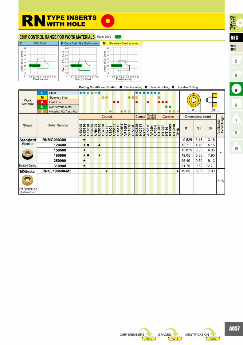
A057
A002A018A010
RNMG 090300 120400 150600 190600 250900 310900RNGJ 190600-M5
�
A195
KNS
MP
D1 S1 D2
s
s
s
s
s
s
a
a
[
s
s s
UE6
005
UE6
110
UE6
020
UE6
035
UH
6400
UC
6010
US7
020
US7
35U
S905
UC
5105
UC
5115
VP05
RT
VP10
RT
VP15
TFU
P20M
NX2
525
NX3
035
NX5
5A
P25N
VP25
NU
P35N
UTi
20T
HTi
05T
HTi
10R
T900
5R
T901
0TF
15
12.7
19.0525.40
19.05
9.52
4.76
6.35
6.35
5.169.525 3.18 3.18
15.875 6.35 6.35
31.75 9.52 12.7
7.939.12
7.93
MP P
RN
0 0.1 0.2 0.3 0.4 0.5 0.6 0.7 0.8
1.0
2.0
3.0
4.0
5.0
6.0
7.0
8.0
0 0.1 0.2 0.3 0.4 0.5 0.6 0.7 0.8
1.0
2.0
3.0
4.0
5.0
6.0
7.0
8.0
0 0.1 0.2 0.3 0.4 0.5 0.6 0.7 0.8
1.0
2.0
3.0
4.0
5.0
6.0
7.0
8.0
D1 S1
øD2
Coated Cermet CoatedCermet Carbide
Order Number Shape
Work Material
SteelStainless SteelCast Iron Non-ferrous Metal Heat-resistant Alloy, Titanium Alloy
Dimensions (mm)
App
licab
leH
olde
r Pag
e
Cutting Conditions (Guide) : : Stable Cutting : General Cutting : Unstable Cutting
TUR
NIN
GIN
SER
TS
NEG
WITHHOLE
Breaker
Medium Cutting
Breaker
For Special Use(For Rotary Tools)
CHIP CONTROL RANGE FOR WORK MATERIALS Medium Cutting
Dep
th o
f Cut
( mm
)
Feed (mm/rev)
Dep
th o
f Cut
( mm
)
Feed (mm/rev)
Dep
th o
f Cut
( mm
)
Feed (mm/rev)
Mild Steel Carbon Steel · Alloy Steel (180 �280HB) Stainless Steel (<200HB)
StandardStandardStandard
TYPE INSERTSWITH HOLE
Standard
M5
IDENTIFICATIONGRADESCHIP BREAKERS
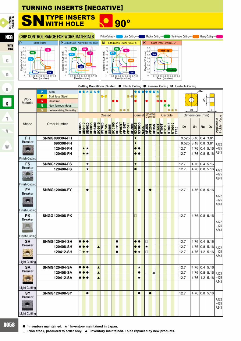
A058
SNMG 090304-FH 090308-FH 120404-FH 120408-FH
SNMG 120404-FS 120408-FS
SNMG 120408-FY
SNGG 120408-PK
SNMG 120404-SH 120408-SH 120412-SH
SNMG 120404-SA 120408-SA 120412-SA
SNMG 120408-SY
KNS
MP
ReD1 S1 D2
a
a
r
a
a
a
s
s
a
a
s
a
a
a
s
s
s
s
a
a
a
s
a
a
a
a
[
[
[
[
a
a
a
s
s
a
a
s
a
r
a
a
a
a
a
a
a
a
s
s
a
s
a
r
s
r
a
a
[
UE6
005
UE6
110
UE6
020
UE6
035
UH
6400
UC
6010
US7
020
US7
35U
S905
UC
5105
UC
5115
VP05
RT
VP10
RT
VP15
TFU
P20M
NX2
525
NX3
035
NX5
5A
P25N
VP25
NU
P35N
UTi
20T
HTi
05T
HTi
10R
T900
5R
T901
0TF
15
4.76 0.8 5.1612.7
3.18 0.4 3.813.18 0.8 3.814.76 0.4 5.164.76 0.8 5.16
4.76 0.4 5.164.76 0.8 5.16
4.76 0.8 5.16
4.76 0.4 5.164.76 0.8 5.164.76 1.2 5.16
4.76 0.4 5.164.76 0.8 5.164.76 1.2 5.16
12.712.712.7
9.525 9.52512.712.7
12.712.7
4.76 0.8 5.1612.7
12.7
12.712.712.7
A172�175A243
A172�175A243
A172�175A243
A172�175A243
A172�175A243
A172�175A243
A172�175A243
KMP P
SN 90°
D1
Re
S1
øD2
0 0.1 0.2 0.3 0.4 0.5 0.6 0.7 0.8
1.0
2.0
3.0
4.0
5.0
6.0
7.0
8.0
0 0.1 0.2 0.3 0.4 0.5 0.6 0.7 0.8
1.0
2.0
3.0
4.0
5.0
6.0
7.0
8.0
SH
FH
GH
HX
HV
MV
0 0.1 0.2 0.3 0.4 0.5 0.6 0.7 0.8
1.0
2.0
3.0
4.0
5.0
6.0
7.0
8.0
0 0.1 0.2 0.3 0.4 0.5 0.6 0.7 0.8
1.0
2.0
3.0
4.0
5.0
6.0
7.0
8.0
SH
GH
HLMS
FS MA
FY
SY
MH
HLMS
Light Cutting
Breaker
Finish Cutting
Breaker
Finish Cutting
Finish Cutting
Finish Cutting
Light Cutting
Light Cutting
Breaker
Breaker
Breaker
Breaker
Breaker
SY
FY
FH
FS
PK
SH
SA
Coated Cermet CoatedCermet Carbide
Order Number Shape
Work Material
SteelStainless SteelCast Iron Non-ferrous Metal Heat-resistant Alloy, Titanium Alloy
Dimensions (mm)
App
licab
leH
olde
r Pag
e
Cutting Conditions (Guide) : : Stable Cutting : General Cutting : Unstable Cutting
NEG
WITHHOLE
TUR
NIN
GIN
SER
TS
CHIP CONTROL RANGE FOR WORK MATERIALS
Dep
th o
f Cut
( mm
)
Feed (mm/rev)
Dep
th o
f Cut
( mm
)
Feed (mm/rev)
Dep
th o
f Cut
( mm
)
Feed (mm/rev)
Dep
th o
f Cut
( mm
)
Feed (mm/rev)
Finish Cutting Light Cutting Medium Cutting Semi-Heavy Cutting Heavy Cutting
Mild Steel Carbon Steel · Alloy Steel (180 �280HB) Stainless Steel (<200HB) Cast Iron (<350N/mm2)
TURNING INSERTS [NEGATIVE]
TYPE INSERTSWITH HOLE
: Non stock, produced to order only.r
: Inventory maintained.a : Inventory maintained in Japan.s
: Inventory maintained. To be replaced by new products.[
Standard
Flat Top
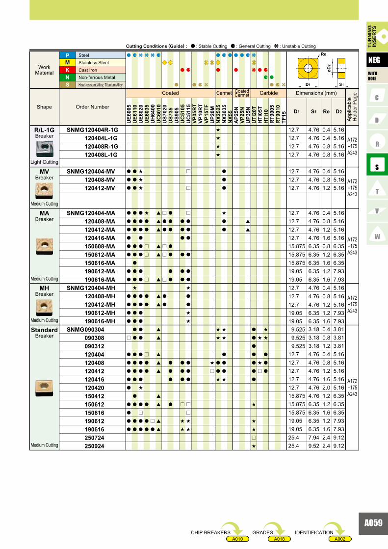
A059
A002A018A010
SNMG 120404R-1G 120404L-1G 120408R-1G 120408L-1G
SNMG 120404-MV 120408-MV 120412-MV
SNMG 120404-MA 120408-MA 120412-MA 120416-MA 150608-MA 150612-MA 150616-MA 190612-MA 190616-MASNMG 120404-MH 120408-MH 120412-MH 190612-MH 190616-MHSNMG 090304 090308 090312 120404 120408 120412 120416 120420 150412 150612 150616 190612 190616 250724 250924
KNS
MP
ReD1 S1 D2
UE6
005
UE6
110
UE6
020
UE6
035
UH
6400
UC
6010
US7
020
US7
35U
S905
UC
5105
UC
5115
VP05
RT
VP10
RT
VP15
TFU
P20M
NX2
525
NX3
035
NX5
5A
P25N
VP25
NU
P35N
UTi
20T
HTi
05T
HTi
10R
T900
5R
T901
0TF
15
a
a
a
a
a
a
a
a
a
a
a
a
a
a
a
r
a
a
a
a
a
a
a
a
a
a
a
a
a
a
a
a
a
a
a
a
s
a
a
a
a
a
a
a
a
a
a
a
a
a
a
s
s
s
a
a
a
a
a
a
a
a
a
a
a
a
a
a
a
a
a
a
s
a
r
a
a
s
a
a
r
r
r
a
a
r
a
a
a
a
a
r
a
[
[
[
[
[
[
[
[
[
[
[
[
[
[
[
[
[
r
a
a
r
r
r
a
a
a
a
a
a
a
a
a
a
a
a
a
a
a
a
a
a
a
a
a
a
r
s
s
r
r
r
a
a
a
a
a
a
s
a
a
s
s
a
a
a
r
r
s
s
s
r
s
s
s
s
s
s
a
a
s
a
a
a
s
a
a
s
s
a
a
a
s
[
[
a
a
a
a
a
a
a
s
s
s
r
s
s
s
r
s
s
a
a
a
4.764.764.764.76
4.764.764.76
4.764.76
4.764.764.76
6.356.35
6.35
3.183.183.184.764.764.764.764.76
6.35
6.356.357.949.52
6.35
4.76
6.35
6.356.35
0.40.40.80.8
0.40.81.2
0.81.2
0.40.81.2
0.81.2
1.6
0.40.81.20.40.81.21.62.0
1.2
1.21.62.42.4
1.6
1.2
1.2
1.21.6
5.165.165.165.16
5.165.165.16
5.165.16
5.165.165.16
6.356.35
7.93
3.813.813.815.165.165.165.165.16
6.35
7.937.939.129.12
6.35
6.35
7.93
7.937.93
9.525
15.87515.875
15.875
25.425.419.0519.05
12.712.712.712.712.7
15.875
19.056.35 1.6 6.3515.875
4.76 0.4 5.1612.7
15.875
9.5259.525
19.05
12.74.76 1.6 5.1612.7
12.712.7
12.712.7
19.0519.05
12.712.712.7
12.712.712.712.7
A172�175A243
A172�175A243
A172�175A243
A172�175A243
A172�175A243
D1
Re
S1
øD2
Breaker
Breaker
Light Cutting
Medium Cutting
Medium Cutting
Medium Cutting
Medium Cutting
Breaker
Breaker
Breaker
Standard
R/L-1G
MV
MA
MH
Coated Cermet CoatedCermet Carbide
Order NumberShape
WorkMaterial
SteelStainless Steel Cast IronNon-ferrous MetalHeat-resistant Alloy, Titanium Alloy
Dimensions (mm)
App
licab
leH
olde
r Pag
e
Cutting Conditions (Guide) : : Stable Cutting : General Cutting : Unstable Cutting TUR
NIN
GIN
SER
TS
NEG
WITHHOLE
IDENTIFICATIONGRADESCHIP BREAKERS

A060
SNMG 090304-MS 090308-MS 120404-MS 120408-MS 120412-MS 120416-MS 150608-MS 150612-MS 190616-MSSNGG 090304R 090304L 090308R 090308L 120404R 120404L 120408R 120408L 120412RSNMG 120408-GH 120412-GH 120416-GH 150612-GH 150616-GH 190612-GH 190616-GHSNMM 120408-HL 120412-HL 150612-HL 150616-HL 190612-HL 190616-HL 190624-HL
KNS
MP
ReD1 S1 D2
a
a
a
a
a
s
a
s
a
a
a
a
a
a
a
a
a
a
a
a
a
a
s
a
a
a
a
a
a
a
a
a
a
a
a
a
a
a
a
a
a
r
r
r
[
[
[
[
[
[
[
[
[
[
r
r
r
a
a
r
r
r
r
a
a
a
a
s
s
r
s
a
a
a
s
r
a
a
a
a
a
a
a
a
a
a
a
a
a
a
a
a
a
a
s
a
a
r
r
s
s
s
s
s
s
s
s
s
s
s
a
a
s
s
s
s
s
s
a
s
a
a
s
s
s
s
s
s
s
s
s
r
r
a
a
r
r
UE6
005
UE6
110
UE6
020
UE6
035
UH
6400
UC
6010
US7
020
US7
35U
S905
UC
5105
UC
5115
VP05
RT
VP10
RT
VP15
TFU
P20M
NX2
525
NX3
035
NX5
5A
P25N
VP25
NU
P35N
UTi
20T
HTi
05T
HTi
10R
T900
5R
T901
0TF
15
A172�175A243
A172�175A243
A172�175A243
3.18 0.4 3.813.18 0.8 3.814.76 0.4 5.164.76 0.8 5.164.76 1.2 5.164.76 1.6 5.166.35 0.8 6.356.35 1.2 6.356.35 1.6 7.933.18 0.4 3.813.18 0.4 3.813.18 0.8 3.813.18 0.8 3.814.76 0.4 5.164.76 0.4 5.164.76 0.8 5.164.76 0.8 5.164.76 1.2 5.164.76 0.8 5.164.76 1.2 5.164.76 1.6 5.166.35 1.2 6.35
6.35 1.2 7.936.35 1.6 7.93
12.715.875
6.35 1.6 6.3515.875
19.0519.05
15.87515.875
12.712.712.712.712.712.712.7
9.5259.5259.5259.525
19.05
12.712.712.712.7 9.525 9.525
KMP P
SN 90°
4.76 0.8 5.164.76 1.2 5.166.35 1.2 6.35
6.35 1.2 7.936.35 1.6 7.936.35 2.4 7.93
15.875
12.712.7
19.056.35 1.6 6.3515.875
19.0519.05
A172�175A243
D1
Re
S1
øD2
0 0.1 0.2 0.3 0.4 0.5 0.6 0.7 0.8
1.0
2.0
3.0
4.0
5.0
6.0
7.0
8.0
0 0.1 0.2 0.3 0.4 0.5 0.6 0.7 0.8
1.0
2.0
3.0
4.0
5.0
6.0
7.0
8.0
SH
FH
GH
HX
HV
MV
0 0.1 0.2 0.3 0.4 0.5 0.6 0.7 0.8
1.0
2.0
3.0
4.0
5.0
6.0
7.0
8.0
0 0.1 0.2 0.3 0.4 0.5 0.6 0.7 0.8
1.0
2.0
3.0
4.0
5.0
6.0
7.0
8.0
SH
GH
HLMS
FS MA
FY
SY
MH
HLMS
Breaker
Breaker
Breaker
Medium Cutting
Medium Cutting
Semi-HeavyCutting
MS
R/L
GH
Coated Cermet CoatedCermet Carbide
Order Number Shape
Work Material
SteelStainless SteelCast Iron Non-ferrous Metal Heat-resistant Alloy, Titanium Alloy
Dimensions (mm)
App
licab
leH
olde
r Pag
e
Cutting Conditions (Guide) : : Stable Cutting : General Cutting : Unstable Cutting
NEG
WITHHOLE
TUR
NIN
GIN
SER
TS
CHIP CONTROL RANGE FOR WORK MATERIALS
Dep
th o
f Cut
( mm
)
Feed (mm/rev)
Dep
th o
f Cut
( mm
)
Feed (mm/rev)
Dep
th o
f Cut
( mm
)
Feed (mm/rev)
Dep
th o
f Cut
( mm
)
Feed (mm/rev)
Finish Cutting Light Cutting Medium Cutting Semi-Heavy Cutting Heavy Cutting
Mild Steel Carbon Steel · Alloy Steel (180 �280HB) Stainless Steel (<200HB) Cast Iron (<350N/mm2)
TURNING INSERTS [NEGATIVE]
TYPE INSERTSWITH HOLE
: Non stock, produced to order only.r
: Inventory maintained.a : Inventory maintained in Japan.s
: Inventory maintained. To be replaced by new products.[
Standard
Flat Top
Heavy Cutting
BreakerHL

A061
A002A018A010
SNMM 150612-HM 150616-HM 190612-HM 190616-HM 190624-HM 250724-HM 250924-HMSNMM 150612-HX 150616-HX 190612-HX 190616-HX 190624-HX 250724-HX 250924-HXSNMM 190616-HV 190624-HV 250724-HV 250924-HV
SNMM 190616-HCS 190624-HCS 250724-HCS 250924-HCS
SNMA 090304 090308 090312 120404 120408 120412 120416 190612 190616SNGA 090302 090304 090308 120404 120408 120412
KNS
MP
ReD1 S1 D2
UE6
005
UE6
110
UE6
020
UE6
035
UH
6400
UC
6010
US7
020
US7
35U
S905
UC
5105
UC
5115
VP05
RT
VP10
RT
VP15
TFU
P20M
NX2
525
NX3
035
NX5
5A
P25N
VP25
NU
P35N
UTi
20T
HTi
05T
HTi
10R
T900
5R
T901
0TF
15
a
a
a
a
a
a
a
a
a
a
a
a
a
a
a
a
a
a
a
a
a
a
a
a
a
a
a
a
a
a
a
a
a
a
a
a
a
a
a
a
a
a
a
a
a
a
a
a
a
a
a
a
a
a
a
a
a
a
a
a
a
a
a
a
a
a
a
a
a
[
a
a
a
a
a
a
a
s
a
a
a
a
a
s
a
a
a
a
a
s
s
s
r
s
a
a
s
s
s
s
s
s
s
s
s
s
s
s
r
a
a
r
a
a
a
a
a
a
a
a
6.35 1.2 7.936.35 1.6 7.93
7.94 2.4 9.12
19.05
6.35 1.2 6.3515.8756.35 1.6 6.3515.875
6.35 2.4 7.9319.05
9.52 2.4 9.1225.4
6.35 1.6 6.3515.875
6.35 1.6 7.9319.056.35 2.4 7.9319.057.94 2.4 9.1225.4
19.05
25.4
A172A174
A172A174
A172A174
A172A174
6.35 1.2
6.35 1.26.35 1.66.35 2.47.94 2.49.52 2.4
15.875
25.425.419.0519.0519.05
6.35
7.937.937.939.129.12
6.35 1.6 7.936.35 2.4 7.937.94 2.4 9.129.52 2.4 9.12
19.0519.0525.425.4
9.52 2.4 9.1225.4
A172�175A243
A172�175A243
3.18 0.4 3.813.18 0.8 3.813.18 1.2 3.814.76 0.4 5.164.76 0.8 5.164.76 1.2 5.164.76 1.6 5.166.35 1.2 7.936.35 1.6 7.933.18 0.2 3.813.18 0.4 3.813.18 0.8 3.814.76 0.4 5.164.76 0.8 5.164.76 1.2 5.16
9.52512.712.712.712.719.0519.05
9.5259.5259.525
12.712.712.7
9.5259.525
D1
Re
S1
øD2
Breaker
Heavy Cutting
Heavy Cutting
Heavy Cutting
Breaker
Breaker
HX
HV
HCS
Coated Cermet CoatedCermet Carbide
Order NumberShape
WorkMaterial
SteelStainless Steel Cast IronNon-ferrous MetalHeat-resistant Alloy, Titanium Alloy
Dimensions (mm)
App
licab
leH
olde
r Pag
e
Cutting Conditions (Guide) : : Stable Cutting : General Cutting : Unstable Cutting TUR
NIN
GIN
SER
TS
NEG
WITHHOLE
Heavy Cutting
BreakerHM
Flat Top
Flat Top
IDENTIFICATIONGRADESCHIP BREAKERS

A062
TNMG 110304-FH 160404-FH 160408-FH
TNMG 160404-FS 160408-FS
TNMG 160404-FY 160408-FY
TNGG 160404-PK 160408-PK
TNGG 160402R-F 160402L-F 160404R-F 160404L-F 160408R-F 160408L-FTNMG 160404-SH 160408-SH 160412-SH 220408-SH
KNS
MP
ReD1 S1 D2
a
a
a
a
a
a
a
a
a
s
s
s
s
s
a
a
a
a
s
[
[
[
[
[
a
a
a
a
a
a
a
s
s
s
s
s
s
s
a
a
a
a
a
a
s
s
s
s
s
s
a
a
a
a
a
a
a
a
a
a
a
s
s
a
a
s
r
s
s
s
s
s
a
a
UE6
005
UE6
110
UE6
020
UE6
035
UH
6400
UC
6010
US7
020
US7
35U
S905
UC
5105
UC
5115
VP05
RT
VP10
RT
VP15
TFU
P20M
NX2
525
NX3
035
NX5
5A
P25N
VP25
NU
P35N
UTi
20T
HTi
05T
HTi
10R
T900
5R
T901
0TF
15
A176�178A243A261A267
A176�178A243A261A267
A176�178A243A261A267
A176�178A243A261A267
A176�178A243A261A267
KP P MP
3.18 0.4 2.264.76 0.4 3.814.76 0.8 3.81
4.76 0.4 3.814.76 0.8 3.81
4.76 0.4 3.814.76 0.8 3.81
4.76 0.2 3.814.76 0.2 3.814.76 0.4 3.814.76 0.4 3.814.76 0.8 3.814.76 0.8 3.819.525
9.5259.5259.5259.5259.525
9.5259.525
9.5259.525
4.76 0.4 3.814.76 0.8 3.819.525
9.525
9.5259.5256.35
TN 60°
A176�178A243A261A267
4.76 0.4 3.814.76 0.8 3.814.76 1.2 3.814.76 0.8 5.1612.7
9.5259.5259.525
0 0.1 0.2 0.3 0.4 0.5 0.6 0.7 0.8
1.0
2.0
3.0
4.0
5.0
6.0
7.0
8.0
SH
FH
GH
HLMV
0 0.1 0.2 0.3 0.4 0.5 0.6 0.7 0.8
1.0
2.0
3.0
4.0
5.0
6.0
7.0
8.0
FS
SH
GH
MS
0 0.1 0.2 0.3 0.4 0.5 0.6 0.7 0.8
1.0
2.0
3.0
4.0
5.0
6.0
7.0
8.0
SW MW
D1
Re
S1
øD2
0 0.1 0.2 0.3 0.4 0.5 0.6 0.7 0.8
1.0
2.0
3.0
4.0
5.0
6.0
7.0
8.0
MA
0 0.1 0.2 0.3 0.4 0.5 0.6 0.7 0.8
1.0
2.0
3.0
4.0
5.0
6.0
7.0
8.0
FY
SY
MH
HLMS
HL
TURNING INSERTS [NEGATIVE]
Coated Cermet CoatedCermet Carbide
Order NumberShape
WorkMaterial
SteelStainless Steel Cast IronNon-ferrous MetalHeat-resistant Alloy, Titanium Alloy
Dimensions (mm)
App
licab
leH
olde
r Pag
e
Cutting Conditions (Guide) : : Stable Cutting : General Cutting : Unstable Cutting
NEG
WITHHOLE
TUR
NIN
GIN
SER
TS
CHIP CONTROL RANGE FOR WORK MATERIALS
Breaker
Breaker
Breaker
Breaker
Dep
th o
f Cut
( mm
)
Feed (mm/rev)
Dep
th o
f Cut
( mm
)
Feed (mm/rev)
Dep
th o
f Cut
( mm
)
Feed (mm/rev)
Dep
th o
f Cut
( mm
)
Feed (mm/rev)
Dep
th o
f Cut
( mm
)
Feed (mm/rev)
Finish Cutting
Finish Cutting
Breaker
Finish Cutting
Finish Cutting
Finish Cutting
Finish Cutting Light Cutting Medium Cutting Semi-Heavy Cutting Heavy Cutting
Mild Steel Carbon Steel · Alloy Steel (180 �280HB) Stainless Steel (<200HB) Cast Iron (<350N/mm2)Carbon Steel · Alloy Steel (Wiper)
TYPE INSERTSWITH HOLE
R/L-F
PK
FH
FS
FY
Standard
Flat Top
Breaker
Light Cutting
SH
: Non stock, produced to order only.r
: Inventory maintained.a : Inventory maintained in Japan.s
: Inventory maintained. To be replaced by new products.[

A063
A002A018A010
TNMG 160404-SA 160408-SA 160412-SA 220408-SA 220412-SATNMX 160404-SW 160408-SW
TNMG 160404-SY 160408-SY
TNMG 160404R-1M 160404L-1M
TNMG 160404R-1G 160404L-1G 160408R-1G 160408L-1G 220404R-1G 220404L-1G 220408R-1G 220408L-1GTNMG 160404-MV 160408-MV 160412-MV 220408-MV 220412-MVTNMG 160404-MA 160408-MA 160412-MA 160416-MA 220408-MA 220412-MA 220416-MA 270608-MA 270612-MA
KNS
MP
ReD1 S1 D2
UE6
005
UE6
110
UE6
020
UE6
035
UH
6400
UC
6010
US7
020
US7
35U
S905
UC
5105
UC
5115
VP05
RT
VP10
RT
VP15
TFU
P20M
NX2
525
NX3
035
NX5
5A
P25N
VP25
NU
P35N
UTi
20T
HTi
05T
HTi
10R
T900
5R
T901
0TF
15
a
a
a
a
a
a
a
a
a
a
a
a
a
a
a
a
a
a
a
a
a
a
a
a
a
a
a
a
a
a
a
a
s
s
a
a
a
a
a
a
a
s
a
s
s
s
a
a
a
a
a
a
a
s
a
a
a
a
s
[
[
[
[
[
[
[
[
[
[
[
[
a
a
a
a
a
a
r
a
r
r
a
a
a
a
a
a
a
a
a
a
a
a
a
a
a
a
a
a
a
a
a
a
a
a
a
a
s
s
s
s
s
s
s
s
a
a
s
a
a
a
a
a
a
a
a
a
a
a
a
a
a
[
[
[
[
[
[
A176
4.76 0.4 3.814.76 0.8 3.814.76 1.2 3.814.76 0.8 5.164.76 1.2 5.16
4.76 0.4 3.814.76 0.4 3.814.76 0.8 3.814.76 0.8 3.814.76 0.4 5.164.76 0.4 5.164.76 0.8 5.164.76 0.8 5.1612.7
12.712.712.79.5259.5259.5259.525
12.712.79.525
4.76 0.4 3.819.5254.76 0.8 3.819.525
4.76 0.8 3.819.5254.76 0.4 3.819.525
4.76 0.4 3.819.5254.76 0.4 3.819.525
9.5259.525 A176
�178A243A261A267
A176�178A243A261A267
A176�178A243A261A267
A176�178A243A261A267
A176�178A243A261A267
A176�178A243A261A267
4.76 0.4 3.814.76 0.8 3.814.76 1.2 3.814.76 0.8 5.164.76 1.2 5.1612.7
12.79.5259.5259.525
4.76 0.4 3.814.76 0.8 3.814.76 1.2 3.81
4.76 0.8 5.164.76 1.2 5.16
6.35 0.8 6.356.35 1.2 6.35
15.87515.875
12.74.76 1.6 5.1612.7
12.7
9.5254.76 1.6 3.819.525
9.5259.525
D1
Re
S1
øD2
Breaker
Breaker
Breaker
Breaker
Light Cutting
Light Cutting
Light Cutting
Light Cutting(Wiper)
R/L-1G
SA
SW
SY
*
R/L-1MBreaker
Light Cutting
Breaker
Medium Cutting
Medium Cutting
Breaker
MA
MV
Coated Cermet CoatedCermet Carbide
Order NumberShape
WorkMaterial
SteelStainless Steel Cast IronNon-ferrous MetalHeat-resistant Alloy, Titanium Alloy
Dimensions (mm)
App
licab
leH
olde
r Pag
e
Cutting Conditions (Guide) : : Stable Cutting : General Cutting : Unstable Cutting TUR
NIN
GIN
SER
TS
NEG
WITHHOLE
*Please refer to page A016 before using the SW breaker (wiper insert).
IDENTIFICATIONGRADESCHIP BREAKERS

A064
A176�178A243A261A267
A176�178A243A261A267
4.76 0.4 3.814.76 0.8 3.814.76 1.2 3.814.76 0.8 5.164.76 1.2 5.1612.7
12.79.5259.5259.525
3.18 0.4 2.263.18 0.8 2.263.18 0.4 3.813.18 0.8 3.814.76 0.4 3.814.76 0.8 3.814.76 1.2 3.814.76 1.6 3.814.76 2.0 3.814.76 0.4 5.164.76 0.8 5.164.76 1.2 5.164.76 1.6 5.166.35 0.8 6.356.35 1.2 6.356.35 1.6 6.359.52 2.4 7.93
9.525
15.87515.87515.875
19.05
12.712.712.712.79.525
9.5259.5259.5259.5259.525
6.35 6.35
A176�178A243A261A267
4.76 1.2 3.814.76 0.8 5.164.76 1.2 5.1612.7
12.79.525
4.76 0.4 3.814.76 0.8 3.819.525
9.525
A176
4.76 0.8 3.819.5254.76 1.2 3.819.525
TNMG 160404-MH 160408-MH 160412-MH 220408-MH 220412-MHTNMG 110304 110308 160304 160308 160404 160408 160412 160416 160420 220404 220408 220412 220416 270608 270612 270616 330924TNMX 160408-MW 160412-MW
TNMG 160404-MS 160408-MS 160412-MS 220408-MS 220412-MS
KNS
MP
ReD1 S1 D2
a
a
a
a
a
a
a
a
a
a
a
a
a
a
a
a
a
a
a
a
a
s
r
r
a
a
a
a
a
a
a
a
s
s
s
a
a
a
s
s
s
a
a
a
a
a
a
a
r
a
a
a
a
r
a
a
a
a
a
r
a
a
s
s
r
a
a
a
a
a
a
s
a
a
[
[
[
[
[
[
[
s
s
[
[
[
s
[
[
[
[
[
s
s
[
[
[
a
a
a
a
a
a
a
a
a
a
a
r
a
a
a
a
a
a
a
a
a
a
s
s
a
a
a
a
a
s
a
a
s
s
a
a
a
s
s
a
a
a
a
a
a
a
a
a
a
a
a
a
a
r
a
a
a
a
a
s
s
a
a
a
s
s
a
a
a
s
s
s
s
s
s
s
s
s
s
a
a
a
s
s
a
a
a
s
a
a
a
a
s
s
s
a
s
s
s
a
a
a
a
r
r
r
a
a
a
r
r
r
UE6
005
UE6
110
UE6
020
UE6
035
UH
6400
UC
6010
US7
020
US7
35U
S905
UC
5105
UC
5115
VP05
RT
VP10
RT
VP15
TFU
P20M
NX2
525
NX3
035
NX5
5A
P25N
VP25
NU
P35N
UTi
20T
HTi
05T
HTi
10R
T900
5R
T901
0TF
15
KP P MP
TN 60°
0 0.1 0.2 0.3 0.4 0.5 0.6 0.7 0.8
1.0
2.0
3.0
4.0
5.0
6.0
7.0
8.0
SH
FH
GH
HLMV
00 0.1 0.2 0.3 0.4 0.5 0.6 0.7 0.8
1.0
2.0
3.0
4.0
5.0
6.0
7.0
8.0
FS
SH
GH
MS
0 0.1 0.2 0.3 0.4 0.5 0.6 0.7 0.8
1.0
2.0
3.0
4.0
5.0
6.0
7.0
8.0
SW MW
0 0.1 0.2 0.3 0.4 0.5 0.6 0.7 0.8
1.0
2.0
3.0
4.0
5.0
6.0
7.0
8.0
MA
D1
Re
S1
øD2
0 0.1 0.2 0.3 0.4 0.5 0.6 0.7 0.8
1.0
2.0
3.0
4.0
5.0
6.0
7.0
8.0
FY
SY
MH
HLMS
HL
Breaker
Breaker
Medium Cutting
Medium Cutting
Standard
MH
Medium Cutting
Breaker
Breaker
Medium Cutting(Wiper)
MS
MW*
TURNING INSERTS [NEGATIVE]
Coated Cermet CoatedCermet Carbide
Order Number Shape
Work Material
SteelStainless SteelCast Iron Non-ferrous Metal Heat-resistant Alloy, Titanium Alloy
Dimensions (mm)
App
licab
leH
olde
r Pag
e
Cutting Conditions (Guide) : : Stable Cutting : General Cutting : Unstable Cutting
NEG
WITHHOLE
TUR
NIN
GIN
SER
TS
CHIP CONTROL RANGE FOR WORK MATERIALS
Dep
th o
f Cut
( mm
)
Feed (mm/rev)
Dep
th o
f Cut
( mm
)
Feed (mm/rev)
Dep
th o
f Cut
( mm
)
Feed (mm/rev)
Dep
th o
f Cut
( mm
)
Feed (mm/rev)
Dep
th o
f Cut
( mm
)
Feed (mm/rev)
Finish Cutting Light Cutting Medium Cutting Semi-Heavy Cutting Heavy Cutting
Mild Steel Carbon Steel · Alloy Steel (180 �280HB) Stainless Steel (<200HB) Cast Iron (<350N/mm2)Carbon Steel · Alloy Steel (Wiper)
Standard
Flat Top
*Please refer to page A016 before using the MW breaker (wiper insert).
TYPE INSERTSWITH HOLE
: Non stock, produced to order only.r
: Inventory maintained.a : Inventory maintained in Japan.s
: Inventory maintained. To be replaced by new products.[

A065
A002A018A010
TNMG 160404-MJ 160408-MJ 160412-MJ
TNMG 160404R-ES 160404L-ES 160408R-ES 160408L-ES 220408R-ES 220408L-ESTNMG 160404L-2M 160404R-2M
TNMG 160404R-2G 160404L-2G 160408R-2G 160408L-2G
TNGG 110302R 110302L 110304R 110304L 110308R 110308L 160304R 160304L 160308R 160308L 160402R 160402L 160404R 160404L 160408R 160408L 160412R 160412L 220404R 220404L 220408R 220408L 220412R 220412L
KNS
MP
ReD1 S1 D2
UE6
005
UE6
110
UE6
020
UE6
035
UH
6400
UC
6010
US7
020
US7
35U
S905
UC
5105
UC
5115
VP05
RT
VP10
RT
VP15
TFU
P20M
NX2
525
NX3
035
NX5
5A
P25N
VP25
NU
P35N
UTi
20T
HTi
05T
HTi
10R
T900
5R
T901
0TF
15
a
a
a
a
a
a
a
a
s
s
a
a
a
a
a
a
a
a
a
r
r
s
s
s
s
s
s
s
s
s
s
s
s
s
s
s
s
a
a
a
a
s
s
s
s
s
s
a
a
s
s
s
s
s
s
s
s
s
s
s
s
a
a
a
a
s
s
s
s
s
s
a
a
r
s
s
s
s
s
a
a
a
a
a
a
a
a
a
s
s
s
s
s
s
r
s
s
s
s
a
a
r
s
s
s
s
s
s
a
a
a
a
a
a
a
a
a
a
a
a
aA176�178A243A261A267
A176�178A243A261A267
A176�178A243A261A267
A176�178A243A261A267
A176�178A243A261A267
4.76 0.4 3.814.76 0.8 3.81
4.76 0.4 3.814.76 0.4 3.814.76 0.8 3.814.76 0.8 3.814.76 0.8 5.164.76 0.8 5.16
4.76 0.4 3.814.76 0.4 3.814.76 0.8 3.814.76 0.8 3.81
3.18 0.2 2.263.18 0.2 2.263.18 0.4 2.263.18 0.4 2.263.18 0.8 2.263.18 0.8 2.266.35
6.356.356.356.356.35
9.5259.5259.5259.525
12.712.79.5259.5259.5259.525
4.76 0.4 3.814.76 0.4 3.819.525
9.525
9.5254.76 1.2 3.819.525
9.525
4.76 0.2 3.814.76 0.2 3.814.76 0.4 3.814.76 0.4 3.814.76 0.8 3.814.76 0.8 3.814.76 1.2 3.814.76 1.2 3.814.76 0.4 5.164.76 0.4 5.164.76 0.8 5.164.76 0.8 5.164.76 1.2 5.164.76 1.2 5.16
9.525
12.712.712.712.712.712.7 9.5259.5259.5259.5259.5259.525
9.525
3.18 0.4 3.819.5253.18 0.4 3.819.5253.18 0.8 3.819.5253.18 0.8 3.819.525
D1
Re
S1
øD2
Medium Cutting
Medium Cutting
Medium Cutting
Breaker
Breaker
Breaker
Breaker
MJ
R/L-ES
R/L-2G
R/L
Medium Cutting
BreakerR/L-2M
Medium Cutting
Coated Cermet CoatedCermet Carbide
Order NumberShape
WorkMaterial
SteelStainless Steel Cast IronNon-ferrous MetalHeat-resistant Alloy, Titanium Alloy
Dimensions (mm)
App
licab
leH
olde
r Pag
e
Cutting Conditions (Guide) : : Stable Cutting : General Cutting : Unstable Cutting TUR
NIN
GIN
SER
TS
NEG
WITHHOLE
IDENTIFICATIONGRADESCHIP BREAKERS
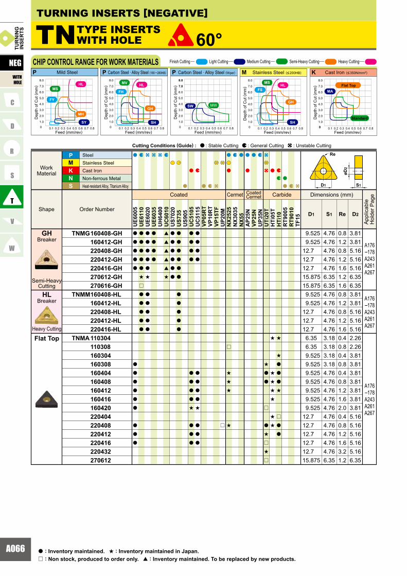
A066
TNMG 160408-GH 160412-GH 220408-GH 220412-GH 220416-GH 270612-GH 270616-GHTNMM 160408-HL 160412-HL 220408-HL 220412-HL 220416-HLTNMA 110304 110308 160304 160308 160404 160408 160412 160416 160420 220404 220408 220412 220416 220432 270612
KNS
MP
ReD1 S1 D2
a
a
a
a
a
a
a
a
a
a
a
a
a
a
a
a
a
a
a
s
r
a
a
a
a
a
a
a
a
a
a
s
a
a
a
a
a
a
a
a
a
[
[
[
[
[
s
a
a
a
a
a
a
a
a
a
a
a
a
a
a
a
a
a
a
a
a
a
a
a
a
a
s
a
a
a
a
a
a
a
a
a
a
a
s
a
a
a
r
r
s
s
s
s
s
a
a
r
a
s
r
s
r
s
s
s
s
s
s
s
s
s
a
a
a
s
r
a
a
UE6
005
UE6
110
UE6
020
UE6
035
UH
6400
UC
6010
US7
020
US7
35U
S905
UC
5105
UC
5115
VP05
RT
VP10
RT
VP15
TFU
P20M
NX2
525
NX3
035
NX5
5A
P25N
VP25
NU
P35N
UTi
20T
HTi
05T
HTi
10R
T900
5R
T901
0TF
15
A176�178A243A261A267
A176�178A243A261A267
4.76 0.8 3.814.76 1.2 3.814.76 0.8 5.164.76 1.2 5.164.76 1.6 5.166.35 1.2 6.35
4.76 0.8 3.814.76 1.2 3.814.76 0.8 5.164.76 1.2 5.164.76 1.6 5.1612.7
12.712.79.5259.525
15.8756.35 1.6 6.3515.875
12.712.712.79.5259.525
KP P MP
TN 60°
A176�178A243A261A267
3.18 0.4 2.263.18 0.8 2.26
3.18 0.8 3.814.76 0.4 3.814.76 0.8 3.814.76 1.2 3.814.76 1.6 3.814.76 2.0 3.814.76 0.4 5.164.76 0.8 5.164.76 1.2 5.164.76 1.6 5.164.76 3.2 5.166.35 1.2 6.3515.875
12.712.712.712.712.79.5259.5259.5259.5259.5259.525
3.18 0.4 3.819.5256.356.35
D1
Re
S1
øD2
0 0.1 0.2 0.3 0.4 0.5 0.6 0.7 0.8
1.0
2.0
3.0
4.0
5.0
6.0
7.0
8.0
SH
FH
GH
HLMV
00 0.1 0.2 0.3 0.4 0.5 0.6 0.7 0.8
1.0
2.0
3.0
4.0
5.0
6.0
7.0
8.0
FS
SH
GH
MS
0 0.1 0.2 0.3 0.4 0.5 0.6 0.7 0.8
1.0
2.0
3.0
4.0
5.0
6.0
7.0
8.0
SW MW
0 0.1 0.2 0.3 0.4 0.5 0.6 0.7 0.8
1.0
2.0
3.0
4.0
5.0
6.0
7.0
8.0
MA
0 0.1 0.2 0.3 0.4 0.5 0.6 0.7 0.8
1.0
2.0
3.0
4.0
5.0
6.0
7.0
8.0
FY
SY
MH
HLMS
HL
Semi-HeavyCutting
Heavy Cutting
Breaker
Breaker
GH
HL
Flat Top
TURNING INSERTS [NEGATIVE]
Coated Cermet CoatedCermet Carbide
Order Number Shape
Work Material
SteelStainless SteelCast Iron Non-ferrous Metal Heat-resistant Alloy, Titanium Alloy
Dimensions (mm)
App
licab
leH
olde
r Pag
e
Cutting Conditions (Guide) : : Stable Cutting : General Cutting : Unstable Cutting
NEG
WITHHOLE
TUR
NIN
GIN
SER
TS
CHIP CONTROL RANGE FOR WORK MATERIALS
Dep
th o
f Cut
( mm
)
Feed (mm/rev)
Dep
th o
f Cut
( mm
)
Feed (mm/rev)
Dep
th o
f Cut
( mm
)
Feed (mm/rev)
Dep
th o
f Cut
( mm
)
Feed (mm/rev)
Dep
th o
f Cut
( mm
)
Feed (mm/rev)
Finish Cutting Light Cutting Medium Cutting Semi-Heavy Cutting Heavy Cutting
Mild Steel Carbon Steel · Alloy Steel (180 �280HB) Stainless Steel (<200HB) Cast Iron (<350N/mm2)Carbon Steel · Alloy Steel (Wiper)
Standard
Flat Top
TYPE INSERTSWITH HOLE
: Non stock, produced to order only.r
: Inventory maintained.a : Inventory maintained in Japan.s
: Inventory maintained. To be replaced by new products.[
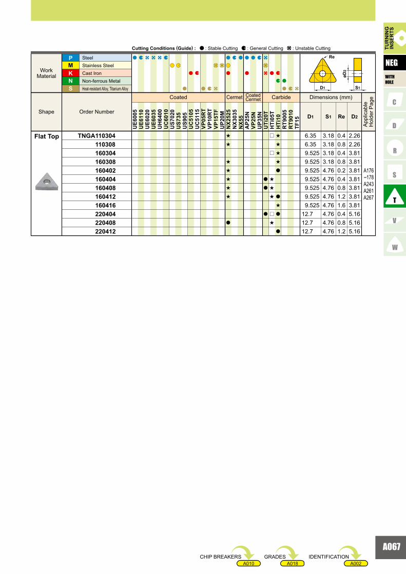
A067
A002A018A010
TNGA 110304 110308 160304 160308 160402 160404 160408 160412 160416 220404 220408 220412
KNS
MP
ReD1 S1 D2
UE6
005
UE6
110
UE6
020
UE6
035
UH
6400
UC
6010
US7
020
US7
35U
S905
UC
5105
UC
5115
VP05
RT
VP10
RT
VP15
TFU
P20M
NX2
525
NX3
035
NX5
5A
P25N
VP25
NU
P35N
UTi
20T
HTi
05T
HTi
10R
T900
5R
T901
0TF
15
s
s
s
s
s
s
s
a
a
a
a
r
r
s
s
s
r
s
s
s
s
s
a
a
s
a
a
A176�178A243A261A267
3.18 0.4 2.263.18 0.8 2.263.18 0.4 3.813.18 0.8 3.814.76 0.2 3.814.76 0.4 3.814.76 0.8 3.814.76 1.2 3.814.76 1.6 3.814.76 0.4 5.164.76 0.8 5.164.76 1.2 5.1612.7
12.712.7 9.525
9.5259.5259.5259.5259.5259.5256.356.35
D1
Re
S1
øD2
Coated Cermet CoatedCermet Carbide
Order NumberShape
WorkMaterial
SteelStainless Steel Cast IronNon-ferrous MetalHeat-resistant Alloy, Titanium Alloy
Dimensions (mm)
App
licab
leH
olde
r Pag
e
Cutting Conditions (Guide) : : Stable Cutting : General Cutting : Unstable Cutting TUR
NIN
GIN
SER
TS
NEG
WITHHOLE
Flat Top
IDENTIFICATIONGRADESCHIP BREAKERS

A068
VNMG 160404-FH 160408-FH
VNMG 160404-FS 160408-FS
VNGG 1604V5-FJ 160401-FJ 160402-FJ
VNMG 160404-SH 160408-SH
VNMG 160404-MV 160408-MV
VNMG 160404-MA 160408-MA
VNMG 160404-MH 160408-MH
KNS
MP
ReD1 S1 D2
a
a
a
a
a
a
s
s
s
s
a
a
a
a
a
a
s
s
s
s
a
a
s
s
a
a
a
a
s
a
a
[
[
[
[
a
a
a
a
a
a
a
a
a
a
a
a
a
a
a
a
a
a
a
a
a
a
a
a
a
a
a
a
a
s
s
a
s
a
a
a
UE6
005
UE6
110
UE6
020
UE6
035
UH
6400
UC
6010
US7
020
US7
35U
S905
UC
5105
UC
5115
VP05
RT
VP10
RT
VP15
TFU
P20M
NX2
525
NX3
035
NX5
5A
P25N
VP25
NU
P35N
UTi
20T
HTi
05T
HTi
10R
T900
5R
T901
0TF
15
A179�181A244A269
A179�181A244A269
A179�181A244A269
A179�181A244A269
A179�181A244A269
A179�181A244A269
KMP P
9.525 4.76 0.4 3.819.525 4.76 0.8 3.81
9.525 4.76 0.4 3.819.525 4.76 0.8 3.81
3.813.81
3.819.525 4.76 0.19.525 4.76 0.2
9.525 4.76 0.05
9.525 4.76 0.4 3.819.525 4.76 0.8 3.81
9.525 4.76 0.4 3.819.525 4.76 0.8 3.81
9.525 4.76 0.4 3.819.525 4.76 0.8 3.81
VN 35°
A179�181A244A269
9.525 4.76 0.4 3.819.525 4.76 0.8 3.81
0 0.1 0.2 0.3 0.4 0.5 0.6 0.7 0.8
1.0
2.0
3.0
4.0
5.0
6.0
7.0
8.0
FS
SH
MS
MH
0 0.1 0.2 0.3 0.4 0.5 0.6 0.7 0.8
1.0
2.0
3.0
4.0
5.0
6.0
7.0
8.0
MV
SH
FH
0 0.1 0.2 0.3 0.4 0.5 0.6 0.7 0.8
1.0
2.0
3.0
4.0
5.0
6.0
7.0
8.0
FS
SH
MS
Re
35°
øD2
S1D1
0 0.1 0.2 0.3 0.4 0.5 0.6 0.7 0.8
1.0
2.0
3.0
4.0
5.0
6.0
7.0
8.0
MA
Breaker
Breaker
Breaker
Breaker
Breaker
Breaker
Finish Cutting
Finish Cutting
Finish Cutting
Light Cutting
Medium Cutting
Medium Cutting
MV
SH
MA
FJ
FH
FS
Breaker
Medium Cutting
MH
TURNING INSERTS [NEGATIVE]
Coated Cermet CoatedCermet Carbide
Order Number Shape
Work Material
SteelStainless SteelCast Iron Non-ferrous Metal Heat-resistant Alloy, Titanium Alloy
Dimensions (mm)
App
licab
leH
olde
r Pag
e
Cutting Conditions (Guide) : : Stable Cutting : General Cutting : Unstable Cutting
NEG
WITHHOLE
TUR
NIN
GIN
SER
TS
CHIP CONTROL RANGE FOR WORK MATERIALS
Dep
th o
f Cut
( mm
)
Feed (mm/rev)
Dep
th o
f Cut
( mm
)
Feed (mm/rev)
Dep
th o
f Cut
( mm
)
Feed (mm/rev)
Dep
th o
f Cut
( mm
)
Feed (mm/rev)
Finish Cutting Light Cutting Medium Cutting Semi-Heavy Cutting
Mild Steel Carbon Steel · Alloy Steel (180 �280HB) Stainless Steel (<200HB) Cast Iron (<350N/mm2)
TYPE INSERTSWITH HOLE
Standard
Flat Top
: Non stock, produced to order only.r
: Inventory maintained.a : Inventory maintained in Japan.s
: Inventory maintained. To be replaced by new products.[

A069
A002A018A010
VNMG 160404 160408 160412
VNMG 160404-MS 160408-MS
VNMG 160404-MJ 160408-MJ 160412-MJ
VNGM 160404-MJ 160408-MJ
VNGG 160404R 160404L 160408R
VNGA 160404 160408
KNS
MP
ReD1 S1 D2
UE6
005
UE6
110
UE6
020
UE6
035
UH
6400
UC
6010
US7
020
US7
35U
S905
UC
5105
UC
5115
VP05
RT
VP10
RT
VP15
TFU
P20M
NX2
525
NX3
035
NX5
5A
P25N
VP25
NU
P35N
UTi
20T
HTi
05T
HTi
10R
T900
5R
T901
0TF
15
a
a
a
a
a
a
s
s
a
a
a
[
[
[
[
[
a
a
a
a
a
a
a
a
a
a
a
a
a
a
a
a
a
a
a
a
a
a
a
a
a
a
a
a
a
a
s
s
a
a
a
s
s
a
a
a
a
a
a
a
a
a
s
s
a
a
a
a
a
a
a
r
r
a
a
a
a
a
a
a
a
A179�181A244A269
A179�181A244A269
A179�181A244A269
A179�181A244A269
A179�181A244A269
A179�181A244A269
9.525 4.76 0.4 3.819.525 4.76 0.8 3.819.525 4.76 1.2 3.81
9.525 4.76 0.4 3.819.525 4.76 0.8 3.81
9.525 4.76 0.4 3.819.525 4.76 0.8 3.81
9.525 4.76 0.49.525 4.76 0.8
9.525 4.76 0.4
3.813.81
9.525 4.76 0.4
3.81
9.525 4.76 1.2 3.81
9.525 4.76 0.8 3.81
9.525 4.76 0.4 3.819.525 4.76 0.8 3.81
3.813.81
Re
35°
øD2
S1D1
Breaker
Breaker
Breaker
Breaker
Breaker
Medium Cutting
Medium Cutting
Medium Cutting
Medium Cutting
Medium Cutting
Flat Top
Standard
R/L
MJ
MJ
MS
Coated Cermet CoatedCermet Carbide
Order NumberShape
WorkMaterial
SteelStainless Steel Cast IronNon-ferrous MetalHeat-resistant Alloy, Titanium Alloy
Dimensions (mm)
App
licab
leH
olde
r Pag
e
Cutting Conditions (Guide) : : Stable Cutting : General Cutting : Unstable Cutting TUR
NIN
GIN
SER
TS
NEG
WITHHOLE
IDENTIFICATIONGRADESCHIP BREAKERS

A070
WNMG 080404-FH 080408-FH
WNMG 080404-FS 080408-FS
WNMG 080404-FY 080408-FY
WNMG 06T304-SH 06T308-SH 06T312-SH 060404-SH 060408-SH 060412-SH 080404-SH 080408-SH 080412-SHWNMG 080404-SA 080408-SA 080412-SA
WNMG 080404-SY 080408-SY
KNS
MP
ReD1 S1 D2
a
a
a
a
a
a
a
a
a
a
a
a
s
s
a
a
a
a
a
s
a
a
a
a
a
a
s
s
s
s
a
a
a
a
s
a
a
a
a
a
[
[
[
[
[
[
[
s
[
[
[
[
[
[
a
a
a
a
a
a
r
a
a
a
a
a
a
a
a
a
a
a
a
a
a
a
a
a
a
s
a
a
s
a
a
s
s
s
a
a
a
a
a
[
[
UE6
005
UE6
110
UE6
020
UE6
035
UH
6400
UC
6010
US7
020
US7
35U
S905
UC
5105
UC
5115
VP05
RT
VP10
RT
VP15
TFU
P20M
NX2
525
NX3
035
NX5
5A
P25N
VP25
NU
P35N
UTi
20T
HTi
05T
HTi
10R
T900
5R
T901
0TF
15
A182A183A244A263
A182A183A244A263
A182A183A244A263
A182A183A244A263
A182A183A244A263
4.76 0.4 5.164.76 0.8 5.16
4.76 0.4 5.164.76 0.8 5.16
3.97 0.4 3.813.97 0.8 3.813.97 1.2 3.814.76 0.4 3.814.76 0.8 3.814.76 1.2 3.814.76 0.4 5.164.76 0.8 5.164.76 1.2 5.164.76 0.4 5.164.76 0.8 5.164.76 1.2 5.16
12.7
12.712.712.712.712.7
9.5259.5259.5259.5259.525
9.525
12.712.7
4.76 0.4 5.164.76 0.8 5.1612.7
12.7
12.712.7
KMPP P
WN 80°
A182A183A244A263
4.76 0.4 5.164.76 0.8 5.16
12.712.7
FS
SH
GH
MS
SH
FH
GH
MV
SW MW
0 0.1 0.2 0.3 0.4 0.5 0.6 0.7 0.8
1.0
2.0
3.0
4.0
5.0
6.0
7.0
8.0
0 0.1 0.2 0.3 0.4 0.5 0.6 0.7 0.8
1.0
2.0
3.0
4.0
5.0
6.0
7.0
8.0
0 0.1 0.2 0.3 0.4 0.5 0.6 0.7 0.8
1.0
2.0
3.0
4.0
5.0
6.0
7.0
8.0
D1
Re
øD2
S180°
0 0.1 0.2 0.3 0.4 0.5 0.6 0.7 0.8
1.0
2.0
3.0
4.0
5.0
6.0
7.0
8.0
MA
0 0.1 0.2 0.3 0.4 0.5 0.6 0.7 0.8
1.0
2.0
3.0
4.0
5.0
6.0
7.0
8.0
FY
SY
MH
MS
Breaker
Finish Cutting
Breaker
Breaker
Breaker
Breaker
Finish Cutting
Finish Cutting
Light Cutting
Light Cutting
FY
SA
SH
FH
FS
Breaker
Light Cutting
SY
TURNING INSERTS [NEGATIVE]
Coated Cermet CoatedCermet Carbide
Order Number Shape
Work Material
SteelStainless SteelCast Iron Non-ferrous Metal Heat-resistant Alloy, Titanium Alloy
Dimensions (mm)
App
licab
leH
olde
r Pag
e
Cutting Conditions (Guide) : : Stable Cutting : General Cutting : Unstable Cutting
NEG
WITHHOLE
TUR
NIN
GIN
SER
TS
CHIP CONTROL RANGE FOR WORK MATERIALS
Dep
th o
f Cut
( mm
)
Feed (mm/rev)
Dep
th o
f Cut
( mm
)
Feed (mm/rev)
Dep
th o
f Cut
( mm
)
Feed (mm/rev)
Dep
th o
f Cut
( mm
)
Feed (mm/rev)
Dep
th o
f Cut
( mm
)
Feed (mm/rev)
Finish Cutting Light Cutting Medium Cutting Semi-Heavy Cutting
Mild Steel Carbon Steel · Alloy Steel (180 �280HB) Stainless Steel (<200HB) Cast Iron (<350N/mm2)Carbon Steel · Alloy Steel (Wiper)
TYPE INSERTSWITH HOLE
Standard
Flat Top
: Non stock, produced to order only.r
: Inventory maintained.a : Inventory maintained in Japan.s
: Inventory maintained. To be replaced by new products.[
Heavy Cutting
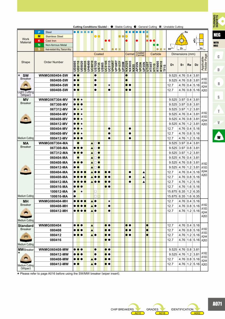
A071
A002A018A010
WNMG 060404-SW 060408-SW 080404-SW 080408-SW
WNMG 06T304-MV 06T308-MV 06T312-MV 060404-MV 060408-MV 060412-MV 080404-MV 080408-MV 080412-MVWNMG 06T304-MA 06T308-MA 06T312-MA 060404-MA 060408-MA 060412-MA 080404-MA 080408-MA 080412-MA 080416-MA 100612-MA 100616-MAWNMG 080404-MH 080408-MH 080412-MH
WNMG 080404 080408 080412 080416
WNMG 060408-MW 060412-MW 080408-MW 080412-MW
KNS
MP
ReS1D1 D2
UE6
005
UE6
110
UE6
020
UE6
035
UH
6400
UC
6010
US7
020
US7
35U
S905
UC
5105
UC
5115
VP05
RT
VP10
RT
VP15
TFU
P20M
NX2
525
NX3
035
NX5
5A
P25N
VP25
NU
P35N
UTi
20T
HTi
05T
HTi
10R
T900
5R
T901
0TF
15
a
a
a
a
a
a
a
a
a
a
a
a
a
a
a
a
a
a
a
a
a
a
a
a
a
a
a
a
a
a
a
a
a
a
a
a
a
a
a
s
a
a
a
a
a
a
a
a
a
a
a
a
a
a
a
a
a
a
a
a
a
a
a
a
a
a
s
a
s
s
s
s
s
s
a
a
a
a
a
a
a
a
s
a
a
a
a
a
a
a
a
a
a
a
a
a
a
a
[
[
[
[
[
[
[
[
[
[
[
[
[
[
[
[
[
a
a
a
a
r
r
r
r
r
r
a
a
a
r
r
a
a
a
a
a
a
a
a
a
a
a
a
a
a
a
a
a
r
a
a
a
a
a
a
a
a
a
a
a
a
s
a
a
a
a
a
a
a
a
s
a
a
a
a
a
a
a
a
a
a
a
a
a
a
a
a
a
a
a
a
a
a
a
a
a
a
a
a
[
[
[
a
a
a
A182A183A244A263
4.76 0.4 5.164.76 0.8 5.1612.7
12.74.76 0.8 3.819.5254.76 0.4 3.819.525
A182A183A244A263
A182A183A244A263
A182A183A244A263
4.76 0.4 3.814.76 0.8 3.814.76 1.2 3.814.76 0.4 5.164.76 0.8 5.164.76 1.2 5.16
4.76 0.4 5.164.76 0.8 5.164.76 1.2 5.16
4.76 0.4 3.814.76 0.8 3.814.76 1.2 3.81
3.97 0.4 3.813.97 0.8 3.813.97 1.2 3.81
4.76 0.4 5.164.76 0.8 5.164.76 1.2 5.16
6.35 1.2 6.356.35 1.6 6.35
12.74.76 1.6 5.1612.7
15.87515.875
9.525
3.97 0.4 3.813.97 0.8 3.813.97 1.2 3.81
9.5259.5259.525
12.712.712.7
12.712.712.7
9.5259.5259.525
9.5259.5259.525
12.712.7
9.5259.525
A182A183A244A263
A182A183A244A263
4.76 0.8 5.164.76 1.2 5.16
4.76 0.4 5.164.76 0.8 5.164.76 1.2 5.164.76 1.6 5.16
12.712.7
12.712.712.712.7
4.76 0.8 3.819.5254.76 1.2 3.819.525
D1
Re
øD2
S180°
Breaker
Light Cutting(Wiper)
SW*
Breaker
Breaker
Breaker
Medium Cutting
Medium Cutting
Medium Cutting
MH
MA
MV
Breaker
Breaker
Medium Cutting(Wiper)
Medium Cutting
Standard
MW*
Coated Cermet CoatedCermet Carbide
Order NumberShape
WorkMaterial
SteelStainless Steel Cast IronNon-ferrous MetalHeat-resistant Alloy, Titanium Alloy
Dimensions (mm)
App
licab
leH
olde
r Pag
e
Cutting Conditions (Guide) : : Stable Cutting : General Cutting : Unstable Cutting TUR
NIN
GIN
SER
TS
NEG
WITHHOLE
* Please refer to page A016 before using the SW/MW breaker (wiper insert).
IDENTIFICATIONGRADESCHIP BREAKERS

A072
WNMG 06T304-MS 06T308-MS 060404-MS 060408-MS 080404-MS 080408-MS 080412-MSWNMG 080408-MJ 080412-MJ 080416-MJ
WNMG 080408-GH 080412-GH
WNMG 080408-GJ 080412-GJ 080416-GJ 100612-GJ
WNMA 080404 080408 080412 080416
KNS
MP
ReD1 S1 D2
a
a
a
a
a
a
a
s
s
a
a
s
a
a
r
r
r
r
a
a
a
a
[
[
[
[
[
[
[
[
[
r
r
a
a
a
a
s
a
a
a
a
a
a
a
a
a
a
a
a
a
a
a
a
a
a
a
a
a
a
a
a
a
a
a
a
a
a
a
a
a
a
a
a
a
a
a
a a
s
s
s
r
a
r
r
a
a
a
r
r
a
a
a
a
a
r
UE6
005
UE6
110
UE6
020
UE6
035
UH
6400
UC
6010
US7
020
US7
35U
S905
UC
5105
UC
5115
VP05
RT
VP10
RT
VP15
TFU
P20M
NX2
525
NX3
035
NX5
5A
P25N
VP25
NU
P35N
UTi
20T
HTi
05T
HTi
10R
T900
5R
T901
0TF
15
KMPP P
WN 80°
A182A183A244A263
A182A183A244A263
A182A183A244A263
A182A183A244A263
A182A183A244A263
3.97 0.4 3.813.97 0.8 3.814.76 0.4 3.814.76 0.8 3.814.76 0.4 5.164.76 0.8 5.164.76 1.2 5.16
4.76 0.8 5.164.76 1.2 5.16
5.165.165.166.35
4.76 0.84.76 1.24.76 1.6
15.875 6.35 1.2
4.76 0.4 5.164.76 0.8 5.164.76 1.2 5.16
12.712.7
12.712.712.79.525
4.76 0.8 5.164.76 1.2 5.164.76 1.6 5.1612.7
12.712.7
9.5259.5259.525
12.712.712.7
12.74.76 1.6 5.1612.7
12.712.7
FS
SH
GH
MS
SH
FH
GH
MV
SW MW
0 0.1 0.2 0.3 0.4 0.5 0.6 0.7 0.8
1.0
2.0
3.0
4.0
5.0
6.0
7.0
8.0
0 0.1 0.2 0.3 0.4 0.5 0.6 0.7 0.8
1.0
2.0
3.0
4.0
5.0
6.0
7.0
8.0
0 0.1 0.2 0.3 0.4 0.5 0.6 0.7 0.8
1.0
2.0
3.0
4.0
5.0
6.0
7.0
8.0
0 0.1 0.2 0.3 0.4 0.5 0.6 0.7 0.8
1.0
2.0
3.0
4.0
5.0
6.0
7.0
8.0
MA
D1
Re
øD2
S180°
0 0.1 0.2 0.3 0.4 0.5 0.6 0.7 0.8
1.0
2.0
3.0
4.0
5.0
6.0
7.0
8.0
FY
SY
MH
MS
Breaker
Breaker
Breaker
Breaker
Medium Cutting
Medium Cutting
Semi-HeavyCutting
Semi-HeavyCutting
Flat Top
MS
MJ
GH
GJ
TURNING INSERTS [NEGATIVE]
Coated Cermet CoatedCermet Carbide
Order Number Shape
Work Material
SteelStainless SteelCast Iron Non-ferrous Metal Heat-resistant Alloy, Titanium Alloy
Dimensions (mm)
App
licab
leH
olde
r Pag
e
Cutting Conditions (Guide) : : Stable Cutting : General Cutting : Unstable Cutting
NEG
WITHHOLE
TUR
NIN
GIN
SER
TSTURNING INSERTS [NEGATIVE]
CHIP CONTROL RANGE FOR WORK MATERIALS
Dep
th o
f Cut
( mm
)
Feed (mm/rev)
Dep
th o
f Cut
( mm
)
Feed (mm/rev)
Dep
th o
f Cut
( mm
)
Feed (mm/rev)
Dep
th o
f Cut
( mm
)
Feed (mm/rev)
Dep
th o
f Cut
( mm
)
Feed (mm/rev)
Finish Cutting Light Cutting Medium Cutting Semi-Heavy Cutting
Mild Steel Carbon Steel · Alloy Steel (180 �280HB) Stainless Steel (<200HB) Cast Iron (<350N/mm2)Carbon Steel · Alloy Steel (Wiper)
TYPE INSERTSWITH HOLE
Standard
Flat Top
: Non stock, produced to order only.r
: Inventory maintained.a : Inventory maintained in Japan.s
: Inventory maintained. To be replaced by new products.[
Heavy Cutting

A073
A002A018A010
SNMN 090304 090308 120308 120404 120408 120412 120416 120420 150412 190412SNGN 090304 090308 120308 120404 120408 120412
KNS
MP
ReD1 S1
a
a
a
a
a
a
a
a
a
a
r
r
s
s
s
s
s
r
a
a
a
a
a
a
a
r
s
r
s
s
s
s
a
s
a
a
a
a
a
a
a
a
a
UE6
005
UE6
110
UE6
020
UE6
035
UH
6400
UC
6010
US7
020
US7
35U
S905
UC
5105
UC
5115
VP05
RT
VP10
RT
VP15
TFU
P20M
NX2
525
NX3
035
NX5
5A
P25N
VP25
NU
P35N
UTi
20T
HTi
05T
HTi
10R
T900
5R
T901
0TF
15
K
�
�
3.18 0.43.18 0.83.18 0.8
4.76 0.84.76 1.24.76 1.64.76 2.0
15.875 4.76 1.24.76 1.23.18 0.43.18 0.83.18 0.84.76 0.44.76 0.84.76 1.2
12.7
12.712.712.712.7
4.76 0.412.7
9.5259.525
19.059.5259.525
12.712.712.712.7
SN 90°
0 0.1 0.2 0.3 0.4 0.5 0.6 0.7 0.8
1.0
2.0
3.0
4.0
5.0
6.0
7.0
8.0
D1
Re
S1
Coated Cermet CoatedCermet Carbide
Order Number Shape
Work Material
SteelStainless SteelCast Iron Non-ferrous Metal Heat-resistant Alloy, Titanium Alloy
Dimensions (mm)
App
licab
leH
olde
r Pag
e
Cutting Conditions (Guide) : : Stable Cutting : General Cutting : Unstable Cutting
TUR
NIN
GIN
SER
TS
NEGMedium CuttingCHIP CONTROL RANGE FOR WORK MATERIALS
Dep
th o
f Cut
( mm
)
Feed (mm/rev)
Flat Top
Cast Iron (<350N/mm2)
Flat Top
Flat Top
TYPE INSERTS WITHOUT HOLE
WITHOUTHOLE
IDENTIFICATIONGRADESCHIP BREAKERS

A074
TNMN 110308 160308 160408 160412 160416 160420 220408 220412TNGN 110304 110308 160304 160308 160404 160408 160412
KNS
MP
ReD1 S1
a
a
a
a
a
a
a
s
a
a
a
s
s
s
a
s
s
s
a
a
a
a
a
a
a
a
a
a
r
r
a
a
a
a
a
a
a
s
UE6
005
UE6
110
UE6
020
UE6
035
UH
6400
UC
6010
US7
020
US7
35U
S905
UC
5105
UC
5115
VP05
RT
VP10
RT
VP15
TFU
P20M
NX2
525
NX3
035
NX5
5A
P25N
VP25
NU
P35N
UTi
20T
HTi
05T
HTi
10R
T900
5R
T901
0TF
15
K
TN 60°
�
�
3.18 0.8
4.76 0.84.76 1.24.76 1.64.76 2.04.76 0.84.76 1.23.18 0.43.18 0.83.18 0.43.18 0.84.76 0.44.76 0.84.76 1.2
9.525
9.5259.5259.5259.5259.5256.356.35
12.712.7
9.5259.5259.525
6.353.18 0.89.525
0 0.1 0.2 0.3 0.4 0.5 0.6 0.7 0.8
1.0
2.0
3.0
4.0
5.0
6.0
7.0
8.0
D1 S1
Re
TURNING INSERTS [NEGATIVE]
Coated Cermet CoatedCermet Carbide
Order Number Shape
Work Material
SteelStainless SteelCast Iron Non-ferrous Metal Heat-resistant Alloy, Titanium Alloy
Dimensions (mm)
App
licab
leH
olde
r Pag
e
Cutting Conditions (Guide) : : Stable Cutting : General Cutting : Unstable Cutting
NEG
TUR
NIN
GIN
SER
TS
CHIP CONTROL RANGE FOR WORK MATERIALS Medium Cutting
Dep
th o
f Cut
( mm
)
Feed (mm/rev)
Flat Top
Cast Iron (<350N/mm2)
TYPE INSERTS WITHOUT HOLE
Flat Top
Flat Top
WITHOUTHOLE
: Non stock, produced to order only.r
: Inventory maintained.a : Inventory maintained in Japan.s
: Inventory maintained. To be replaced by new products.[
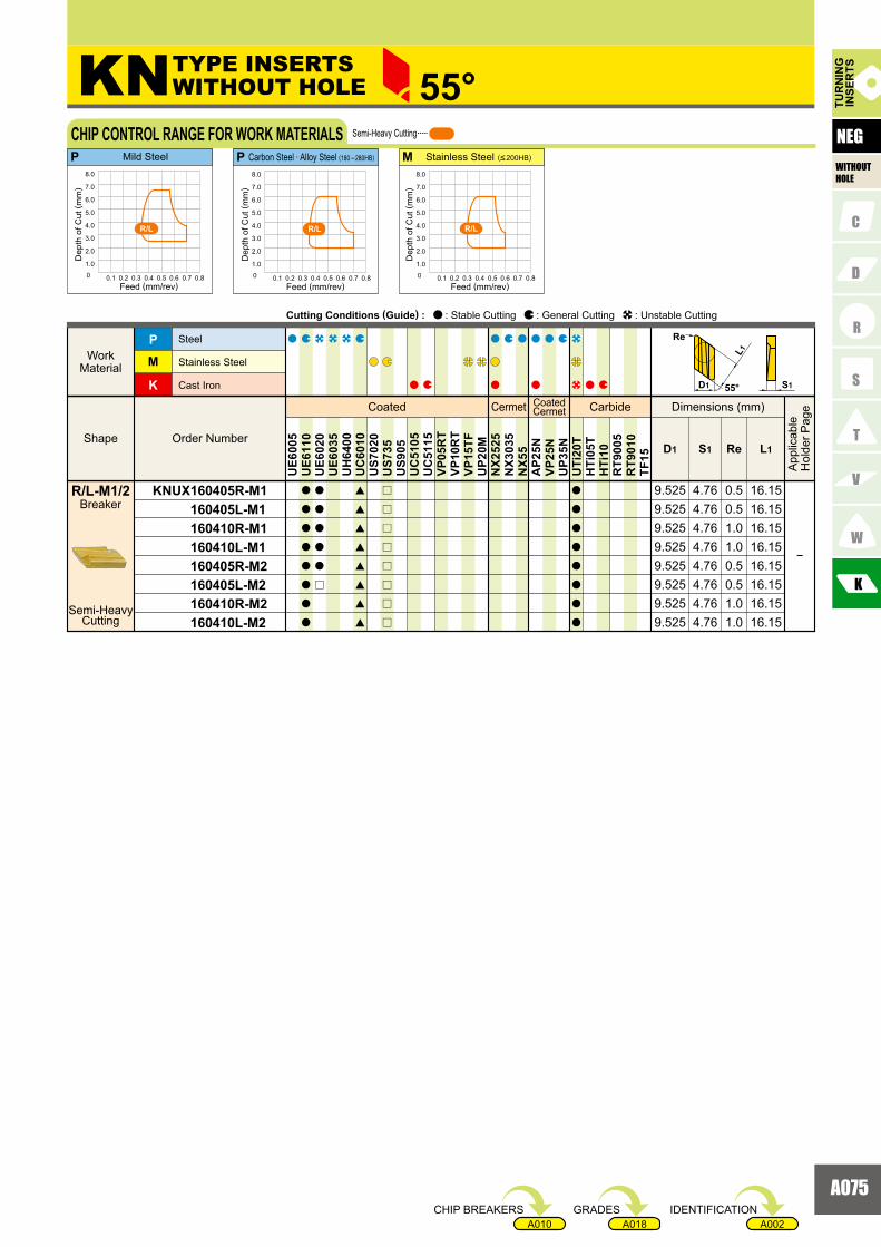
A075
A002A018A010
KNUX 160405R-M1 160405L-M1 160410R-M1 160410L-M1 160405R-M2 160405L-M2 160410R-M2 160410L-M2
K
M
P
ReD1 S1 L1
a
a
a
a
a
a
a
a
a
a
a
a
a
r
[
[
[
[
[
[
[
[
r
r
r
r
r
r
r
r
a
a
a
a
a
a
a
a
UE6
005
UE6
110
UE6
020
UE6
035
UH
6400
UC
6010
US7
020
US7
35U
S905
UC
5105
UC
5115
VP05
RT
VP10
RT
VP15
TFU
P20M
NX2
525
NX3
035
NX5
5A
P25N
VP25
NU
P35N
UTi
20T
HTi
05T
HTi
10R
T900
5R
T901
0TF
15
0.50.51.01.00.50.51.01.0
16.1516.1516.1516.1516.1516.1516.1516.15
9.5259.5259.5259.5259.5259.5259.5259.525
P P M
KN 55°
�
4.764.764.764.764.764.764.764.76
0 0.1 0.2 0.3 0.4 0.5 0.6 0.7 0.8
1.0
2.0
3.0
4.0
5.0
6.0
7.0
8.0
0 0.1 0.2 0.3 0.4 0.5 0.6 0.7 0.8
1.0
2.0
3.0
4.0
5.0
6.0
7.0
8.0
0 0.1 0.2 0.3 0.4 0.5 0.6 0.7 0.8
1.0
2.0
3.0
4.0
5.0
6.0
7.0
8.0
R/L R/LR/L
55°
L1
D1
Re
S1
Semi-HeavyCutting
BreakerR/L-M1/2
Coated Cermet CoatedCermet Carbide
Order NumberShape
WorkMaterial
Steel
Stainless Steel
Cast Iron
Dimensions (mm)
App
licab
leH
olde
r Pag
e
Cutting Conditions (Guide) : : Stable Cutting : General Cutting : Unstable Cutting
TUR
NIN
GIN
SER
TS
NEGCHIP CONTROL RANGE FOR WORK MATERIALS Semi-Heavy Cutting
Dep
th o
f Cut
( mm
)
Feed (mm/rev)
Dep
th o
f Cut
( mm
)
Feed (mm/rev)
Dep
th o
f Cut
( mm
)
Feed (mm/rev)
Mild Steel Carbon Steel · Alloy Steel (180 �280HB) Stainless Steel (<200HB)
TYPE INSERTS WITHOUT HOLE
WITHOUTHOLE
IDENTIFICATIONGRADESCHIP BREAKERS

A076
VBET 1103V3R-SR 1103V3L-SR 110301R-SR 110301L-SR 110302R-SR 110302L-SR 110304R-SR 110304L-SR
VBGT 110302R-F 110302L-F 110304R-F 110304L-F 160402R-F 160402L-F 160404R-F 160404L-FVBMT 110304-SV 110308-SV 160404-SV 160408-SV
VBMT 110304-MV 110308-MV 160404-MV 160408-MV
VBMT 160404 160408
A208A240A241E011
A208A240A241E011
A208A240A241E011
A208A240A241E011
A208A240A241
KNS
MP
ReD1 S1 D2
VB 35°
UE6
005
UE6
110
UE6
020
UE6
035
UH
6400
UC
6010
US7
020
US7
35U
S905
UC
5105
UC
5115
VP05
RT
VP10
RT
VP15
TFU
P20M
NX2
525
NX3
035
NX5
5N
X99
AP2
5NVP
25N
VP45
NU
P35N
UTi
20T
HTi
05T
HTi
10R
T900
5R
T901
0TF
15
a
a
a
a
a
a
a
a
a
a
a
a
a
a
a
a
a
a
s
s
a
a
a
a
a
a
a
a
a
a
a
a
a
a
a
a
a
a
s
s
s
s
s
s
s
s
s
s
s
s
s
s
s
s
a
a
a
a
s
s
s
s
s
s
s
s
a
a
a
a
a
a
a
a
s
s
s
s
s
s
s
s
a
a
a
a
a
a
a
a
s
s
s
s
s
s
s
s
s
s
s
s
s
s
s
s
6.35 3.18 0.26.35 3.18 0.26.35 3.18 0.46.35 3.18 0.49.525 4.76 0.29.525 4.76 0.29.525 4.76 0.49.525 4.76 0.4
6.35 3.18 0.46.35 3.18 0.89.525 4.76 0.49.525 4.76 0.8
6.35 3.18 0.03 2.9
4.54.5
4.54.54.54.5
2.92.9
2.92.92.92.9
6.35 3.18 0.03 2.96.35 3.18 0.1 2.96.35 3.18 0.1 2.96.35 3.18 0.2 2.9
6.35 3.18 0.4 2.856.35 3.18 0.8 2.859.525 4.76 0.4 4.439.525 4.76 0.8 4.43
6.35 3.18 2.96.35 3.18 2.96.35 3.18 2.9
0.20.40.4
9.5259.525
4.764.76
0.40.8
4.54.5
0 0.1 0.2 0.3 0.4
1.0
2.0
3.0
4.0
0 0.1 0.2 0.3 0.4
1.0
2.0
3.0
4.0
0 0.1 0.2 0.3 0.4
1.0
2.0
3.0
4.0
MP P
SVR/L-F MV
SVR/L-F
MV
SVR/L-F
MV
35° S1D1
Re
5°
øD2
Breaker
Medium Cutting
Standard
Breaker
Medium Cutting
MV
Finish Cutting
Coated Cermet CoatedCermet Carbide
Order NumberShape
WorkMaterial
SteelStainless Steel Cast IronNon-ferrous MetalHeat-resistant Alloy, Titanium Alloy
Dimensions (mm)
App
licab
leH
olde
r Pag
e
Cutting Conditions (Guide) : : Stable Cutting : General Cutting : Unstable Cutting
POSI5°
WITHHOLE
TYPE INSERTSWITH HOLE
TURNING INSERTS [POSITIVE]
Medium Cutting
BreakerR/L-SR
TUR
NIN
GIN
SER
TS
Medium CuttingCHIP CONTROL RANGE FOR WORK MATERIALS
Dep
th o
f Cut
( mm
)
Feed (mm/rev)
Dep
th o
f Cut
( mm
)
Feed (mm/rev)
Dep
th o
f Cut
( mm
)
Feed (mm/rev)
Finish Cutting
Mild Steel Carbon Steel · Alloy Steel (180 �280HB) Stainless Steel (<200HB)
BreakerR/L-F
Breaker
Light Cutting
SV
: Inventory maintained.a : Inventory maintained in Japan.s
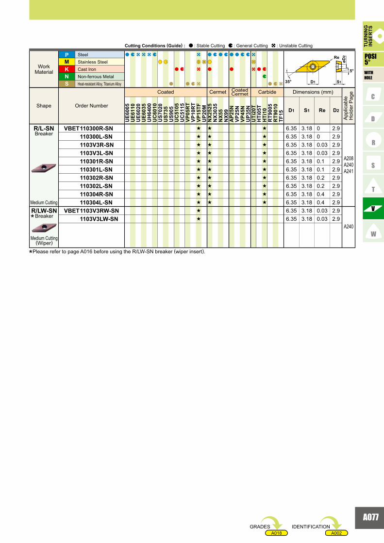
A077
A002A018
VBET 110300R-SN 110300L-SN 1103V3R-SN 1103V3L-SN 110301R-SN 110301L-SN 110302R-SN 110302L-SN 110304R-SN 110304L-SNVBET 1103V3RW-SN 1103V3LW-SN
A208A240A241
A240
KNS
MP
ReD1 S1 D2
s
s
s
s
s
s
s
s
s
s
s
s
s
s
s
s
s
s
s
s
s
s
s
s
s
s
s
s
s
s
s
s
UE6
005
UE6
110
UE6
020
UE6
035
UH
6400
UC
6010
US7
020
US7
35U
S905
UC
5105
UC
5115
VP05
RT
VP10
RT
VP15
TFU
P20M
NX2
525
NX3
035
NX5
5N
X99
AP2
5NVP
25N
VP45
NU
P35N
UTi
20T
HTi
05T
HTi
10R
T900
5R
T901
0TF
15
6.35 3.18 0 2.96.35 3.18 0 2.96.35 3.18 0.03 2.96.35 3.18 0.03 2.96.35 3.18 0.1 2.96.35 3.18 0.1 2.96.35 3.18 0.2 2.96.35 3.18 0.2 2.96.35 3.18 0.4 2.96.35 3.18 0.4 2.96.35 3.18 0.036.35 3.18 0.03 2.9
2.9
35° S1D1
Re
5°
øD2
TUR
NIN
GIN
SER
TS
Coated Cermet CoatedCermet Carbide
Order NumberShape
WorkMaterial
SteelStainless Steel Cast IronNon-ferrous MetalHeat-resistant Alloy, Titanium Alloy
Dimensions (mm)
App
licab
leH
olde
r Pag
e
Cutting Conditions (Guide) : : Stable Cutting : General Cutting : Unstable Cutting
POSI5°
WITHHOLE
Breaker
Medium Cutting(Wiper)
R/LW-SN*
Medium Cutting
BreakerR/L-SN
*Please refer to page A016 before using the R/LW-SN breaker (wiper insert).
IDENTIFICATIONGRADES
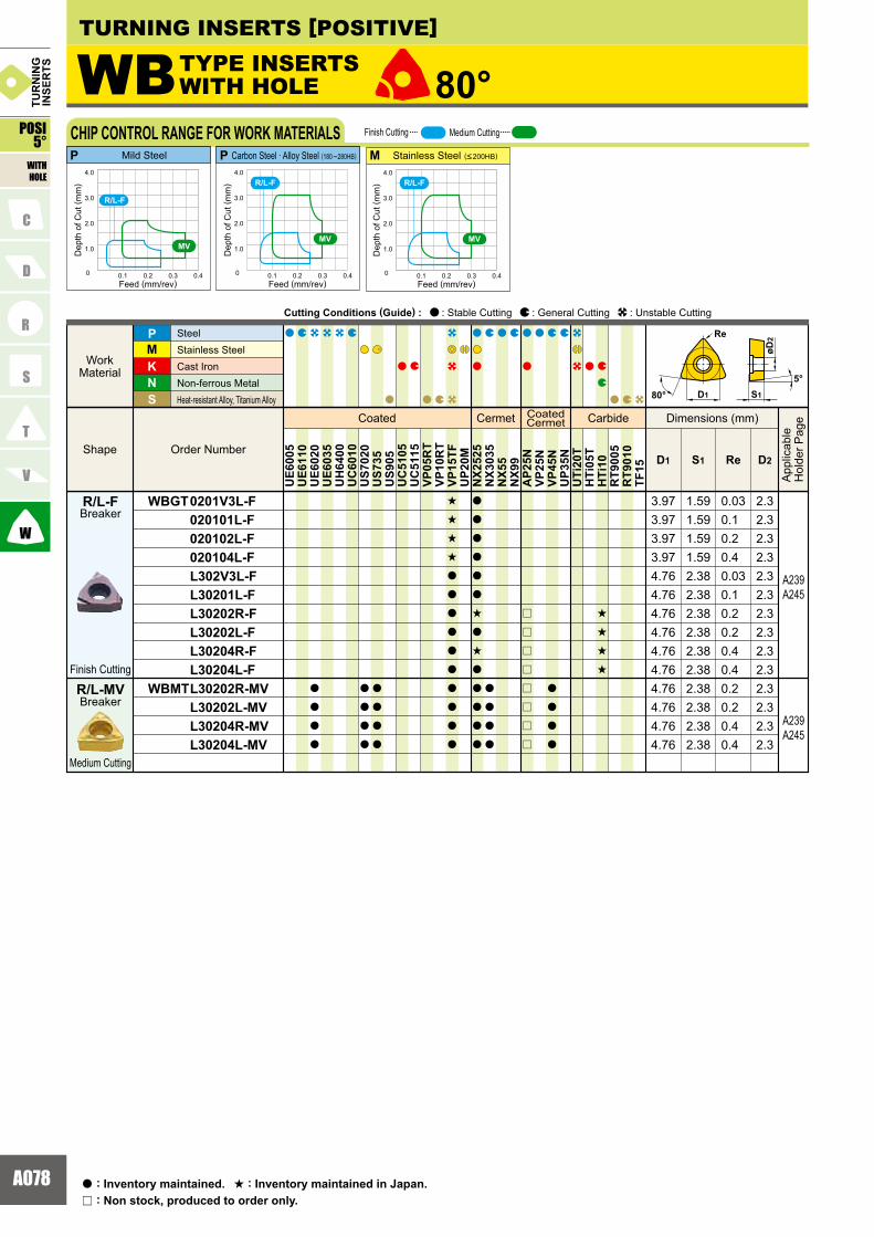
A078
WBGT 0201V3L-F 020101L-F 020102L-F 020104L-F L302V3L-F L30201L-F L30202R-F L30202L-F L30204R-F L30204L-FWBMT L30202R-MV L30202L-MV L30204R-MV L30204L-MV
A239A245
A239A245
KNS
MP
ReD1 S1 D2
UE6
005
UE6
110
UE6
020
UE6
035
UH
6400
UC
6010
US7
020
US7
35U
S905
UC
5105
UC
5115
VP05
RT
VP10
RT
VP15
TFU
P20M
NX2
525
NX3
035
NX5
5N
X99
AP2
5NVP
25N
VP45
NU
P35N
UTi
20T
HTi
05T
HTi
10R
T900
5R
T901
0TF
15
a
a
a
a
a
a
a
a
a
a
a
a
s
s
s
s
a
a
a
a
a
a
a
a
a
a
a
a
a
a
a
a
s
a
s
a
a
a
a
a
a
a
a
a
r
r
r
r
r
r
r
r
a
a
a
a
s
s
s
s
WB 80°
3.97 1.59 0.03 2.33.97 1.59 0.1 2.33.97 1.59 0.2 2.33.97 1.59 0.4 2.34.76 2.38 0.03 2.34.76 2.38 0.1 2.34.76 2.38 0.2 2.34.76 2.38 0.2 2.34.76 2.38 0.4 2.34.76 2.38 0.4 2.34.76 2.38 0.2 2.34.76 2.38 0.2 2.34.76 2.38 0.4 2.34.76 2.38 0.4 2.3
0 0.1 0.2 0.3 0.4
1.0
2.0
3.0
4.0
MV
R/L-F
0 0.1 0.2 0.3 0.4
1.0
2.0
3.0
4.0
MV
R/L-F
0 0.1 0.2 0.3 0.4
1.0
2.0
3.0
4.0
MV
R/L-F
MP P
S180°5°
Re
øD2
D1
Coated Cermet CoatedCermet Carbide
Order Number Shape
Work Material
SteelStainless SteelCast Iron Non-ferrous Metal Heat-resistant Alloy, Titanium Alloy
Dimensions (mm)
App
licab
leH
olde
r Pag
e
Cutting Conditions (Guide) : : Stable Cutting : General Cutting : Unstable Cutting
POSI5°
WITHHOLE
TUR
NIN
GIN
SER
TS
CHIP CONTROL RANGE FOR WORK MATERIALS
Dep
th o
f Cut
( mm
)
Feed (mm/rev)
Dep
th o
f Cut
( mm
)
Feed (mm/rev)
Dep
th o
f Cut
( mm
)
Feed (mm/rev)
Finish Cutting
Mild Steel Carbon Steel · Alloy Steel (180 �280HB) Stainless Steel (<200HB)
Medium Cutting
TURNING INSERTS [POSITIVE]
TYPE INSERTSWITH HOLE
Breaker
Finish Cutting
R/L-F
Breaker
Medium Cutting
R/L-MV
: Non stock, produced to order only.r
: Inventory maintained.a : Inventory maintained in Japan.s

A079
A002A018A012
CCMT 060202-FV 060204-FV 09T304-FV 09T308-FV
CCGT 09T301-FJ 09T302-FJ 09T304-FJ
CCGT 03S1V3L-F 03S101L-F 03S102L-F 03S104L-F 04T0V3L-F 04T001L-F 04T002L-F 04T004L-FCCGH 060202R-F 060202L-F 060204R-F 060204L-F
CCMH 060202-SV 060204-SV
CCMT 060202-SW 060204-SW 09T302-SW 09T304-SW
KNS
MP
ReD1 S1 D2
UE6
005
UE6
110
UE6
020
UE6
035
UH
6400
UC
6010
US7
020
US7
35U
S905
UC
5105
UC
5115
VP05
RT
VP10
RT
VP15
TFU
P20M
NX2
525
NX3
035
NX5
5N
X99
AP2
5NVP
25N
VP45
NU
P35N
UTi
20T
HTi
05T
HTi
10R
T900
5R
T901
0TF
15
a
a
a
a
a
a
a
a
a
a
a
a
a
a
a
a
a
a
a
a
a
a
a
r
a
a
a
a
a
a
a
a
a
a
a
a
a
a
a
a
a
a
a
a
a
a
a
a
a
a
a
a
a
a
s
s
s
s
a
a
a
a
a
a
a
a
a
a
a
a
a
a
a
a
r
s
r
s
r
r
r
r
a
a
a
a
a
a
s
s
s
s
a
a
a
CC 80°
6.35 2.38 0.2 2.86.35 2.38 0.4 2.89.525 3.97 0.2 4.49.525 3.97 0.4 4.4
6.35 2.38 0.2 2.86.35 2.38 0.4 2.89.525 3.97 0.4 4.49.525 3.97 0.8 4.4
4.44.44.4
9.525 3.97 0.19.525 3.97 0.29.525 3.97 0.4
3.57 1.39 0.03 23.57 1.39 0.1 23.57 1.39 0.2 23.57 1.39 0.4 24.37 1.79 0.03 2.44.37 1.79 0.1 2.44.37 1.79 0.2 2.44.37 1.79 0.4 2.46.35 2.38 0.2 2.86.35 2.38 0.2 2.86.35 2.38 0.4 2.86.35 2.38 0.4 2.8
2.38 0.22.38 0.4 2.8
2.86.356.35
A184A206A235A256A260
A184A206A256A260
A184A206A235A256A260
A245
A184A206A235A256A260
A184A206A235A256A260
0 0.1 0.2 0.3 0.4
1.0
2.0
3.0
4.0
0 0.1 0.2 0.3 0.4
1.0
2.0
3.0
4.0
0 0.1 0.2 0.3 0.4
1.0
2.0
3.0
4.0
MP P
FVSV
FV SV FV SV
7°
øD2
S180° D1
ReRe
Coated Cermet CoatedCermet Carbide
Order Number Shape
Work Material
SteelStainless SteelCast Iron Non-ferrous Metal Heat-resistant Alloy, Titanium Alloy
Dimensions (mm)
App
licab
leH
olde
r Pag
e
Cutting Conditions (Guide) : : Stable Cutting : General Cutting : Unstable Cutting
TUR
NIN
GIN
SER
TS
WITHHOLE
TYPE INSERTSWITH HOLE
CHIP CONTROL RANGE FOR WORK MATERIALS
Dep
th o
f Cut
( mm
)
Feed (mm/rev)
Dep
th o
f Cut
( mm
)
Feed (mm/rev)
Dep
th o
f Cut
( mm
)
Feed (mm/rev)
Mild Steel Carbon Steel · Alloy Steel (180 �280HB) Stainless Steel (<200HB)
Finish Cutting Light Cutting Medium Cutting
Standard
Standard Standard
POSI7°
Breaker
Finish Cutting
FV
Light Cutting(Wiper)
Breaker
Finish Cutting
Finish Cutting
Finish Cutting
Breaker
Breaker
Breaker
Breaker
Light Cutting
*Please refer to page A016 before using the SW breaker (wiper insert).
FJ
L-F
R/L-F
SV
SW*
IDENTIFICATIONGRADESCHIP BREAKERS

A080
CCGT 0602V3R-SS 0602V3L-SS 060201R-SS 060201L-SS 060202R-SS 060202L-SS 09T3V3R-SS 09T3V3L-SS 09T301R-SS 09T301L-SS 09T302R-SS 09T302L-SSCCMH 060202-MV 060204-MV
CCMT 060202 060204 060208 080302 080304 080308 09T302 09T304 09T308 120404 120408 120412
KNS
MP
ReD1 S1 D2
UE6
005
UE6
110
UE6
020
UE6
035
UH
6400
UC
6010
US7
020
US7
35U
S905
UC
5105
UC
5115
VP05
RT
VP10
RT
VP15
TFU
P20M
NX2
525
NX3
035
NX5
5N
X99
AP2
5NVP
25N
VP45
NU
P35N
UTi
20T
HTi
05T
HTi
10R
T900
5R
T901
0TF
15
a
a
a
a
a
a
a
a
a
a
a
a
a
a
a
a
a
a
a
a
a
a
a
a
a
a
r
r
a
a
a
a
a
a
[
[
[
[
[
[
[
[
[
[
[
a
a
a
a
a
a
a
a
a
a
a
a
a
a
a
a
a
a
a
a
a
a
a
a
a
a
s
s
s
s
s
s
s
s
s
s
s
s
a
a
s
r
s
a
a
a
a
r
a
r
a
a
a
a
a
r
a
a
a
a
a
a
a
a
a
a
s
[
[
[
[
[
[
[
[
a
a
s
s
r
s
r
s
s
s
s
s
r
a
a
[
[
[
[
[
[
[
[
a
a
a
a
a
a
a
a
a
CC 80°
2.38 0.03 2.82.38 0.03 2.82.38 0.1 2.82.38 0.1 2.82.38 0.2 2.82.38 0.2 2.83.97 0.03 4.43.97 0.03 4.43.97 0.1 4.43.97 0.1 4.43.97 0.2 4.43.97 0.2 4.4
2.38 0.2 2.82.38 0.4 2.82.38 0.8 2.8
3.18 0.4 3.43.18 0.8 3.43.97 0.2 4.43.97 0.4 4.43.97 0.8 4.44.76 0.4 5.54.76 0.8 5.54.76 1.2 5.5
2.38 0.2 2.82.38 0.4 2.8
6.35
7.943.18 0.2 3.47.94
6.356.35
12.712.7
9.5259.5259.5257.94
12.7
9.525
6.356.356.35
9.525
9.5259.525
9.5259.525
6.35
6.356.356.356.35
A184A206A235A256A260
A184A206A235A256A260
A184A206A235A256A260
0 0.1 0.2 0.3 0.4
1.0
2.0
3.0
4.0
0 0.1 0.2 0.3 0.4
1.0
2.0
3.0
4.0
0 0.1 0.2 0.3 0.4
1.0
2.0
3.0
4.0
MP P
FVSV
FV SV FV SV
7°
øD2
S180° D1
ReRe
Coated Cermet CoatedCermet Carbide
Order Number Shape
Work Material
SteelStainless Steel Cast Iron Non-ferrous Metal Heat-resistant Alloy, Titanium Alloy
Dimensions (mm)
App
licab
leH
olde
r Pag
e
Cutting Conditions (Guide) : : Stable Cutting : General Cutting : Unstable Cutting
WITHHOLE
TUR
NIN
GIN
SER
TS
CHIP CONTROL RANGE FOR WORK MATERIALS
Dep
th o
f Cut
( mm
)
Feed (mm/rev)
Dep
th o
f Cut
( mm
)
Feed (mm/rev)
Dep
th o
f Cut
( mm
)
Feed (mm/rev)
Mild Steel Carbon Steel · Alloy Steel (180 �280HB) Stainless Steel (<200HB)
Finish Cutting Light Cutting Medium Cutting
Standard
Standard Standard
TURNING INSERTS [POSITIVE]
TYPE INSERTSWITH HOLE
POSI7°
: Non stock, produced to order only.r
: Inventory maintained.a : Inventory maintained in Japan.s
: Inventory maintained. To be replaced by new products.[
Breaker
Breaker
Breaker
Light Cutting
Medium Cutting
Medium Cutting
Standard
MV
R/L-SS
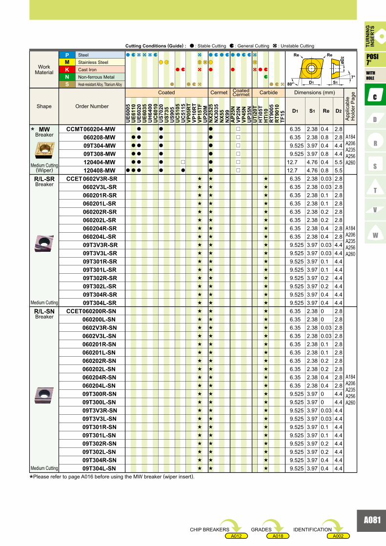
A081
A002A018A012
CCMT 060204-MW 060208-MW 09T304-MW 09T308-MW 120404-MW 120408-MWCCET 0602V3R-SR 0602V3L-SR 060201R-SR 060201L-SR 060202R-SR 060202L-SR 060204R-SR 060204L-SR 09T3V3R-SR 09T3V3L-SR 09T301R-SR 09T301L-SR 09T302R-SR 09T302L-SR 09T304R-SR 09T304L-SRCCET 060200R-SN 060200L-SN 0602V3R-SN 0602V3L-SN 060201R-SN 060201L-SN 060202R-SN 060202L-SN 060204R-SN 060204L-SN 09T300R-SN 09T300L-SN 09T3V3R-SN 09T3V3L-SN 09T301R-SN 09T301L-SN 09T302R-SN 09T302L-SN 09T304R-SN 09T304L-SN
KNS
MP
ReD1 S1 D2
a
a
a
a
a
a
a
a
a
a
a
a
a
a
a
a
a
a
r
a
s
s
s
s
s
s
s
s
s
s
s
s
s
s
s
s
s
s
s
s
s
s
s
s
s
s
s
s
s
s
s
s
s
s
s
s
a
a
a
a
a
a
s
s
s
s
s
s
s
s
s
s
s
s
s
s
s
s
s
s
s
s
s
s
s
s
s
s
s
s
s
s
s
s
s
s
s
s
r
r
r
r
r
r
s
s
s
s
s
s
s
s
s
s
s
s
s
s
s
s
s
s
s
s
s
s
s
s
s
s
s
s
s
s
s
s
s
s
s
s
UE6
005
UE6
110
UE6
020
UE6
035
UH
6400
UC
6010
US7
020
US7
35U
S905
UC
5105
UC
5115
VP05
RT
VP10
RT
VP15
TFU
P20M
NX2
525
NX3
035
NX5
5N
X99
AP2
5NVP
25N
VP45
NU
P35N
UTi
20T
HTi
05T
HTi
10R
T900
5R
T901
0TF
15
6.35 2.38 0.03 2.86.35 2.38 0.03 2.86.35 2.38 0.1 2.86.35 2.38 0.1 2.86.35 2.38 0.2 2.86.35 2.38 0.2 2.86.35 2.38 0.4 2.86.35 2.38 0.4 2.89.525 3.97 0.03 4.49.525 3.97 0.03 4.49.525 3.97 0.1 4.49.525 3.97 0.1 4.49.525 3.97 0.2 4.49.525 3.97 0.2 4.49.525 3.97 0.4 4.49.525 3.97 0.4 4.46.35 2.38 0 2.86.35 2.38 0 2.86.35 2.38 0.03 2.86.35 2.38 0.03 2.86.35 2.38 0.1 2.86.35 2.38 0.1 2.86.35 2.38 0.2 2.86.35 2.38 0.2 2.86.35 2.38 0.4 2.86.35 2.38 0.4 2.89.525 3.97 0 4.49.525 3.97 0 4.49.525 3.97 0.03 4.49.525 3.97 0.03 4.4
2.38 0.4 2.82.38 0.8 2.83.97 0.4 4.43.97 0.8 4.44.76 0.4 5.54.76 0.8 5.5
9.52512.712.7
9.5256.356.35
3.97 0.1 4.43.97 0.2 4.43.97 0.2 4.43.97 0.4 4.43.97 0.4 4.4
9.5259.525
9.5259.525
9.5253.97 0.1 4.49.525
A184A206A235A256A260
A184A206A235A256A260
A184A206A235A256A260
7°
øD2
S180° D1
ReRe
TUR
NIN
GIN
SER
TS
Coated Cermet CoatedCermet Carbide
Order NumberShape
WorkMaterial
SteelStainless Steel Cast IronNon-ferrous MetalHeat-resistant Alloy, Titanium Alloy
Dimensions (mm)
App
licab
leH
olde
r Pag
e
Cutting Conditions (Guide) : : Stable Cutting : General Cutting : Unstable Cutting
WITHHOLE
POSI7°
Medium Cutting
Medium Cutting
Medium Cutting(Wiper)
Breaker
Breaker
Breaker
*
R/L-SR
R/L-SN
MW
IDENTIFICATIONGRADESCHIP BREAKERS
*Please refer to page A016 before using the MW breaker (wiper insert).

A082
CCGT 0602V3R-SN 060201R-SN 060201L-SN 060202R-SN 060202L-SN 09T3V3R-SN 09T3V3L-SN 09T301R-SN 09T301L-SN 09T302R-SN 09T302L-SN 09T304R-SN 09T304L-SNCCET 0602V3RW-SN 0602V3LW-SN 09T3V3RW-SN 09T3V3LW-SN
CCGT 060202-AM 060204-AM
CCGT 060202-AZ 060204-AZ 09T302-AZ 09T304-AZ 09T308-AZ 120402-AZ 120404-AZ 120408-AZ
A184A206A235A256A260
KNS
MP
UE6
005
UE6
110
UE6
020
UE6
035
UH
6400
UC
6010
US7
020
US7
35U
S905
UC
5105
UC
5115
VP05
RT
VP10
RT
VP15
TFU
P20M
NX2
525
NX3
035
NX5
5N
X99
AP2
5NVP
25N
VP45
NU
P35N
UTi
20T
HTi
05T
HTi
10R
T900
5R
T901
0TF
15
s
s
s
s
s
s
s
s
s
s
s
s
s
s
s
s
s
a
a
a
a
a
a
a
a
a
a
CC 80°
2.38 0.03 2.82.38 0.1 2.82.38 0.1 2.82.38 0.2 2.82.38 0.2 2.83.97 0.03 4.43.97 0.03 4.43.97 0.1 4.43.97 0.1 4.43.97 0.2 4.43.97 0.2 4.43.97 0.4 4.43.97 0.4 4.4
2.38 0.2 2.82.38 0.4 2.8
6.35
9.525 9.525
6.35
2.38 0.2 2.8 6.352.38 0.4 2.8 6.353.97 0.2 4.4 9.5253.97 0.4 4.4 9.5253.97 0.8 4.4 9.5254.76 0.2 5.512.74.76 0.4 5.512.74.76 0.8 5.512.7
6.35
2.38 0.03 2.82.38 0.03 2.8 6.353.97 0.03 4.4 9.5253.97 0.03 4.4 9.525
6.35
9.525 9.525
9.525 9.525
9.525
9.525 6.35
6.35 6.35
6.35
ReD1 S1 D2
A184A206A235A256A260
A184A206A235A256A260
A184A206A235A256A260
0 0.1 0.2 0.3 0.4
1.0
2.0
3.0
4.0
0 0.1 0.2 0.3 0.4
1.0
2.0
3.0
4.0
0 0.1 0.2 0.3 0.4
1.0
2.0
3.0
4.0
MP P
FVSV
FV SV FV SV
7°
øD2
S180° D1
ReRe
Coated Cermet CoatedCermet Carbide
Order Number Shape
Work Material
SteelStainless SteelCast Iron Non-ferrous Metal Heat-resistant Alloy, Titanium Alloy
Dimensions (mm)
App
licab
leH
olde
r Pag
e
Cutting Conditions (Guide) : : Stable Cutting : General Cutting : Unstable Cutting
WITHHOLE
TUR
NIN
GIN
SER
TS
POSI7° CHIP CONTROL RANGE FOR WORK MATERIALS
Dep
th o
f Cut
( mm
)
Feed (mm/rev)
Dep
th o
f Cut
( mm
)
Feed (mm/rev)
Dep
th o
f Cut
( mm
)
Feed (mm/rev)
Mild Steel Carbon Steel · Alloy Steel (180 �280HB) Stainless Steel (<200HB)
Finish Cutting Light Cutting Medium Cutting
Standard
Standard Standard
TURNING INSERTS [POSITIVE]
TYPE INSERTSWITH HOLE
Breaker
Medium Cutting
Breaker
Medium Cutting
Breaker
Medium Cutting(Wiper)
*
R/L-SN
R/LW-SN
AM
BreakerAZ
For AluminiumAlloy
*Please refer to page A016 before using the R/LW-SN breaker (wiper insert).
: Non stock, produced to order only.r
: Inventory maintained.a : Inventory maintained in Japan.s
: Inventory maintained. To be replaced by new products.[

A083
A002A018A012
CCMW060202 060204 09T304 09T308 120404 120408 120412CCGW 060200 0602V5 09T300 09T3V5
KNS
MP
ReD1 S1 D2
a
a
a
a
a
a
a
a
a
a
a
a
a
a
a
a
a
a
a
a
[
[
[
[
a
r
a
r
r
a
a
a
a
a
a
UE6
005
UE6
110
UE6
020
UE6
035
UH
6400
UC
6010
US7
020
US7
35U
S905
UC
5105
UC
5115
VP05
RT
VP10
RT
VP15
TFU
P20M
NX2
525
NX3
035
NX5
5N
X99
AP2
5NVP
25N
VP45
NU
P35N
UTi
20T
HTi
05T
HTi
10R
T900
5R
T901
0TF
15
2.38 0 2.82.38 0.05 2.83.97 0 4.43.97 0.05 4.4
9.5259.525
6.356.35
2.38 0.2 2.82.38 0.4 2.83.97 0.4 4.43.97 0.8 4.44.76 0.4 5.54.76 0.8 5.54.76 1.2 5.512.7
12.712.7
9.5259.525
6.356.35
A184A206A235A256A260
A184A206A235A256A260
7°
øD2
S180° D1
ReRe
TUR
NIN
GIN
SER
TS
Coated Cermet CoatedCermet Carbide
Order NumberShape
WorkMaterial
SteelStainless Steel Cast IronNon-ferrous MetalHeat-resistant Alloy, Titanium Alloy
Dimensions (mm)
App
licab
leH
olde
r Pag
e
Cutting Conditions (Guide) : : Stable Cutting : General Cutting : Unstable Cutting
WITHHOLE
POSI7°
IDENTIFICATIONGRADESCHIP BREAKERS
Flat Top
Flat Top

A084
DCMT 070202-FV 070204-FV 11T304-FV 11T308-FV
DCGT 070202R-F 070202L-F 070204R-F 070204L-F 11T302R-F 11T302L-F 11T304R-F 11T304L-FDCMT 070202-SV 070204-SV 070208-SV 11T302-SV 11T304-SV 11T308-SVDCGT 0702V3R-SS 0702V3L-SS 070201R-SS 070201L-SS 070202R-SS 070202L-SS 11T3V3R-SS 11T301R-SS 11T302R-SSDCMT 070202-MV 070204-MV 070208-MV 11T302-MV 11T304-MV 11T308-MV
KNS
MP
ReD1 S1 D2
UE6
005
UE6
110
UE6
020
UE6
035
UH
6400
UC
6010
US7
020
US7
35U
S905
UC
5105
UC
5115
VP05
RT
VP10
RT
VP15
TFU
P20M
NX2
525
NX3
035
NX5
5N
X99
AP2
5NVP
25N
VP45
NU
P35N
UTi
20T
HTi
05T
HTi
10R
T900
5R
T901
0TF
15
a
a
a
a
r
a
a
a
a
a
a
a
a
a
a
a
a
a
a
a
a
a
a
a
a
a
a
a
a
a
a
a
a
a
a
a
a
a
a
a
a
a
a
a
a
a
a
s
s
a
a
a
s
a
a
a
a
a
a
a
a
a
a
a
a
a
a
a
a
a
s
s
s
s
s
s
s
s
s
a
a
a
a
a
a
a
a
a
a
a
a
a
a
a
a
a
a
a
a
a
a
a
a
a
a
a
a
a
a
a
a
a
a
a
a
a
a
a
a
a
a
a
a
a
a
a
a
a
a
r
s
r
s
r
s
r
s
a
a
a
a
a
a
a
a
a
a
a
a
a
a
a
a
a
a
s
s
s
s
s
s
s
s
DC 55°
6.35 2.38 0.2 2.86.35 2.38 0.4 2.89.525 3.97 0.4 4.49.525 3.97 0.8 4.4
6.35 2.38 0.2 2.86.35 2.38 0.2 2.86.35 2.38 0.4 2.86.35 2.38 0.4 2.89.525 3.97 0.2 4.49.525 3.97 0.2 4.49.525 3.97 0.4 4.49.525 3.97 0.4 4.4
4.44.44.4
6.35 2.38 0.26.35 2.38 0.46.35 2.38 0.89.525 3.97 0.29.525 3.97 0.49.525 3.97 0.86.35 2.38 0.03 2.8
2.82.82.8
6.35 2.38 0.03 2.86.35 2.38 0.1 2.86.35 2.38 0.1 2.86.35 2.38 0.2 2.86.35 2.38 0.2 2.89.525 3.97 0.03 4.49.525 3.97 0.1 4.49.525 3.97 0.2 4.4
2.38 0.22.38 0.42.38 0.83.97 0.23.97 0.43.97 0.8
9.5259.525
9.5256.356.356.35 2.8
2.82.84.44.44.4
A185A207A222A237A238A255A257
A185A207A222A237A238A255A257
A185A207A222A237A238A255A257
A185A207A222A237A238A255A257
A185A207A222A237A238A255A257
0 0.1 0.2 0.3 0.4
1.0
2.0
3.0
4.0
0 0.1 0.2 0.3 0.4
1.0
2.0
3.0
4.0
0 0.1 0.2 0.3 0.4
1.0
2.0
3.0
4.0
MP P
FVSV
FV SV FV SV
D155°
Re
7°
øD2
S1
Coated Cermet CoatedCermet Carbide
Order Number Shape
Work Material
SteelStainless SteelCast Iron Non-ferrous Metal Heat-resistant Alloy, Titanium Alloy
Dimensions (mm)
App
licab
leH
olde
r Pag
e
Cutting Conditions (Guide) : : Stable Cutting : General Cutting : Unstable Cutting
WITHHOLE
TUR
NIN
GIN
SER
TS
CHIP CONTROL RANGE FOR WORK MATERIALS
Dep
th o
f Cut
( mm
)
Feed (mm/rev)
Dep
th o
f Cut
( mm
)
Feed (mm/rev)
Dep
th o
f Cut
( mm
)
Feed (mm/rev)
Finish Cutting Light Cutting Medium Cutting
Mild Steel Carbon Steel · Alloy Steel (180 �280HB) Stainless Steel (<200HB)
Standard
Standard Standard
TURNING INSERTS [POSITIVE]
TYPE INSERTSWITH HOLE
POSI7°
Breaker
Finish Cutting
Breaker
Finish Cutting
Breaker
Light Cutting
Breaker
Light Cutting
Breaker
Medium Cutting
MV
FV
R/L-F
SV
R/L-SS
: Non stock, produced to order only.r
: Inventory maintained.a : Inventory maintained in Japan.s
: Inventory maintained. To be replaced by new products.[

A085
A002A018A012
DCMT 070202 070204 070208 11T302 11T304 11T308 11T312 150404 150408 150412DCET 0702V3R-SR 0702V3L-SR 070201R-SR 070201L-SR 070202R-SR 070202L-SR 070204R-SR 070204L-SR 11T3V3R-SR 11T3V3L-SR 11T301R-SR 11T301L-SR 11T302R-SR 11T302L-SR 11T304R-SR 11T304L-SRDCET 070200R-SN 070200L-SN 0702V3R-SN 0702V3L-SN 070201R-SN 070201L-SN 070202R-SN 070202L-SN 070204R-SN 070204L-SN 11T300R-SN 11T300L-SN 11T3V3R-SN 11T3V3L-SN 11T301R-SN 11T301L-SN 11T302R-SN 11T302L-SN 11T304R-SN 11T304L-SN
KNS
MP
ReD1 S1 D2
a
a
a
a
a
a
a
r
a
a
a
s
a
a
a
a
a
a
a
a
a
a
r
[
[
[
[
[
[
[
[
[
a
a
r
a
a
a
a
a
r
a
a
a
a
a
a
a
a
s
s
s
s
s
s
s
s
s
s
s
s
s
s
s
s
s
s
s
s
s
s
s
s
s
s
s
s
s
s
s
s
s
s
s
s
a
a
a
a
a
a
a
a
s
s
s
s
s
s
s
s
s
s
s
s
s
s
s
s
s
s
s
s
s
s
s
s
s
s
s
s
s
s
s
s
s
s
s
s
a
a
a
a
a
a
a
a
[
[
[
[
[
[
[
[
a
a
s
a
s
s
s
s
[
[
[
[
[
[
[
[
a
a
a
a
a
a
a
r
r
r
r
r
r
s
s
s
s
s
s
s
s
s
s
s
s
s
s
s
s
s
s
s
s
s
s
s
s
s
s
s
s
s
s
s
s
s
s
s
s
UE6
005
UE6
110
UE6
020
UE6
035
UH
6400
UC
6010
US7
020
US7
35U
S905
UC
5105
UC
5115
VP05
RT
VP10
RT
VP15
TFU
P20M
NX2
525
NX3
035
NX5
5N
X99
AP2
5NVP
25N
VP45
NU
P35N
UTi
20T
HTi
05T
HTi
10R
T900
5R
T901
0TF
15
2.38 0.22.38 0.42.38 0.83.97 0.23.97 0.43.97 0.8
4.76 0.44.76 0.84.76 1.22.38 0.032.38 0.032.38 0.12.38 0.12.38 0.22.38 0.22.38 0.42.38 0.43.97 0.033.97 0.033.97 0.13.97 0.13.97 0.23.97 0.23.97 0.43.97 0.42.38 02.38 02.38 0.032.38 0.032.38 0.12.38 0.12.38 0.22.38 0.22.38 0.42.38 0.4
9.525
6.35
6.356.35
6.356.35
6.35
6.356.35
6.356.35
9.5259.5259.5259.525
6.35
9.525
9.5259.525
6.35
6.35
6.356.35
6.356.356.35
12.712.712.7
6.35
9.5259.525
3.97 1.29.525
9.5256.35
6.35 2.82.82.84.44.44.4
5.55.55.52.82.82.82.82.82.82.82.84.44.44.44.44.44.44.44.42.82.82.82.82.82.82.82.82.82.8
4.4
9.525 3.97 0 4.49.525 3.97 0 4.49.525 3.97 0.03 4.49.525 3.97 0.03 4.49.525 3.97 0.1 4.49.525 3.97 0.1 4.49.525 3.97 0.2 4.49.525 3.97 0.2 4.49.525 3.97 0.4 4.49.525 3.97 0.4 4.4
A185A207A222A237A238A255A257
A185A207A222A237A238A255A257
A185A207A222A237A238A255A257
D155°
Re
7°
øD2
S1
TUR
NIN
GIN
SER
TS
Coated Cermet CoatedCermet Carbide
Order NumberShape
WorkMaterial
SteelStainless Steel Cast IronNon-ferrous MetalHeat-resistant Alloy, Titanium Alloy
Dimensions (mm)
App
licab
leH
olde
r Pag
e
Cutting Conditions (Guide) : : Stable Cutting : General Cutting : Unstable Cutting
WITHHOLE
POSI7°
Medium Cutting
Breaker
Medium Cutting
Breaker
Breaker
Medium Cutting
Standard
R/L-SR
R/L-SN
IDENTIFICATIONGRADESCHIP BREAKERS

A086
DCGT 0702V3R-SN 070201R-SN 070202R-SN 070202L-SN 11T3V3R-SN 11T3V3L-SN 11T301R-SN 11T301L-SN 11T302R-SN 11T302L-SN 11T304R-SN 11T304L-SNDCET 0702V3RW-SN 0702V3LW-SN 11T3V3RW-SN 11T3V3LW-SN
DCGT 070202-AM 070204-AM 11T302-AM 11T304-AM
DCGT 070202-AZ 070204-AZ 11T302-AZ 11T304-AZ 11T308-AZ
A185A207A222A237A238A255A257
KNS
MP
ReD1 S1 D2
UE6
005
UE6
110
UE6
020
UE6
035
UH
6400
UC
6010
US7
020
US7
35U
S905
UC
5105
UC
5115
VP05
RT
VP10
RT
VP15
TFU
P20M
NX2
525
NX3
035
NX5
5N
X99
AP2
5NVP
25N
VP45
NU
P35N
UTi
20T
HTi
05T
HTi
10R
T900
5R
T901
0TF
15
s
s
s
s
s
s
s
s
s
s
s
s
s
s
s
s
a
a
a
a
a
a
a
a
a
DC 55°
6.35 2.38 0.03 2.86.35 2.38 0.1 2.86.35 2.38 0.2 2.86.35 2.38 0.2 2.89.525 3.97 0.03 4.49.525 3.97 0.03 4.49.525 3.97 0.1 4.49.525 3.97 0.1 4.49.525 3.97 0.2 4.49.525 3.97 0.2 4.49.525 3.97 0.4 4.49.525 3.97 0.4 4.4
6.35 2.38 0.2 2.8
6.35 2.38 0.03 2.86.35 2.38 0.03 2.89.525 3.97 0.03 4.49.525 3.97 0.03 4.4
6.35 2.38 0.4 2.89.525 3.97 0.2 4.49.525 3.97 0.4 4.4
6.35 2.38 0.4 2.86.35 2.38 0.2 2.8
9.525 3.97 0.2 4.4
9.525 3.97 0.8 4.49.525 3.97 0.4 4.4
A185A207A222A237A238A255A257
A185A207A222A237A238A255
A185A207A222A237A238A255A257
0 0.1 0.2 0.3 0.4
1.0
2.0
3.0
4.0
0 0.1 0.2 0.3 0.4
1.0
2.0
3.0
4.0
0 0.1 0.2 0.3 0.4
1.0
2.0
3.0
4.0
MP P
FVSV
FV SV FV SV
D155°
Re
7°
øD2
S1
Coated Cermet CoatedCermet Carbide
Order Number Shape
Work Material
SteelStainless SteelCast Iron Non-ferrous Metal Heat-resistant Alloy, Titanium Alloy
Dimensions (mm)
App
licab
leH
olde
r Pag
e
Cutting Conditions (Guide) : : Stable Cutting : General Cutting : Unstable Cutting
WITHHOLE
TUR
NIN
GIN
SER
TS
CHIP CONTROL RANGE FOR WORK MATERIALS
Dep
th o
f Cut
( mm
)
Feed (mm/rev)
Dep
th o
f Cut
( mm
)
Feed (mm/rev)
Dep
th o
f Cut
( mm
)
Feed (mm/rev)
Finish Cutting Light Cutting Medium Cutting
Mild Steel Carbon Steel · Alloy Steel (180 �280HB) Stainless Steel (<200HB)
Standard
Standard Standard
TURNING INSERTS [POSITIVE]
TYPE INSERTSWITH HOLE
POSI7°
Breaker
Medium Cutting
Breaker
Medium Cutting
Breaker
Medium Cutting(Wiper)
*
R/L-SN
AM
R/LW-SN
*Please refer to page A016 before using the R/LW-SN breaker (wiper insert).
: Non stock, produced to order only.r
: Inventory maintained.a : Inventory maintained in Japan.s
BreakerAZ
For Aluminium Alloy

A087
A002A018A012
DCMW 070202 070204 11T302 11T304 11T308 150404 150408DCGW 070200 0702V5 11T300 11T3V5 11T304
KNS
MP
ReD1 S1 D2
a
a
a
r
a
a
a
a
r
a
a
a
a
a
r
a
r
a
r
a
a
a
a
UE6
005
UE6
110
UE6
020
UE6
035
UH
6400
UC
6010
US7
020
US7
35U
S905
UC
5105
UC
5115
VP05
RT
VP10
RT
VP15
TFU
P20M
NX2
525
NX3
035
NX5
5N
X99
AP2
5NVP
25N
VP45
NU
P35N
UTi
20T
HTi
05T
HTi
10R
T900
5R
T901
0TF
15
2.38 0.2 2.82.38 0.4 2.8
3.97 0.4 4.43.97 0.8 4.44.76 0.4 5.54.76 0.8 5.52.38 0 2.82.38 0.05 2.83.97 0 4.43.97 0.05 4.4
6.35
9.5253.97 0.4 4.49.525
9.5256.35
6.35
12.712.7
9.5259.525
6.35
3.97 0.2 4.49.525
A185A207A222A237A238A255A257
A185A207A222A237A238A255A257
D155°
Re
7°
øD2
S1
TUR
NIN
GIN
SER
TS
Coated Cermet CoatedCermet Carbide
Order NumberShape
WorkMaterial
SteelStainless Steel Cast IronNon-ferrous MetalHeat-resistant Alloy, Titanium Alloy
Dimensions (mm)
App
licab
leH
olde
r Pag
e
Cutting Conditions (Guide) : : Stable Cutting : General Cutting : Unstable Cutting
POSI7°
WITHHOLE
Flat Top
Flat Top
IDENTIFICATIONGRADESCHIP BREAKERS
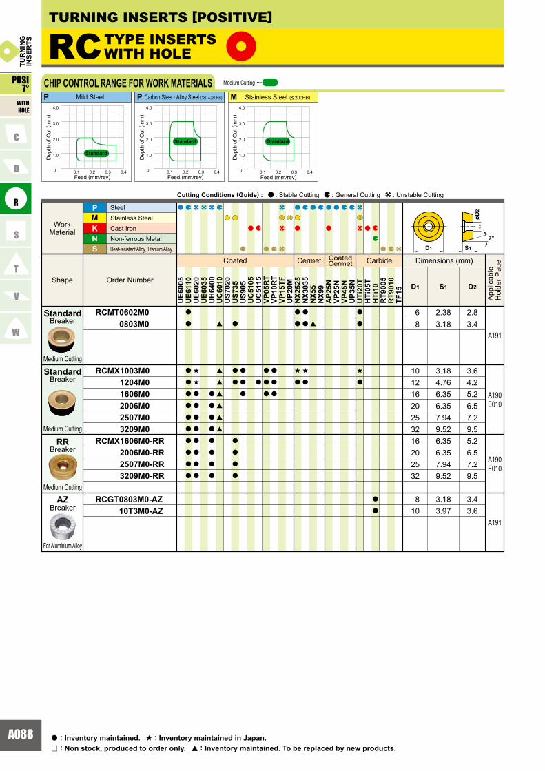
A088
RCMT 0602M0 0803M0
RCMX 1003M0 1204M0 1606M0 2006M0 2507M0 3209M0RCMX 1606M0-RR 2006M0-RR 2507M0-RR 3209M0-RR
RCGT 0803M0-AZ 10T3M0-AZ
8 3.18 3.4
A191
KNS
MP
D1 S1 D2
UE6
005
UE6
110
UE6
020
UE6
035
UH
6400
UC
6010
US7
020
US7
35U
S905
UC
5105
UC
5115
VP05
RT
VP10
RT
VP15
TFU
P20M
NX2
525
NX3
035
NX5
5N
X99
AP2
5NVP
25N
VP45
NU
P35N
UTi
20T
HTi
05T
HTi
10R
T900
5R
T901
0TF
15
a
a
a
a
a
a
a
a
a
a
a
a
s
s
a
a
a
a
a
a
a
a
a
a
a
a
a
a
a
a
[
[
[
[
[
[
[
a
a
a
a
a
a
a
a
a
a
a
a
a
a
a
a
a
a
a
s
a
a
a
s
a
[
a
a
s
a
a
a
RC
6 2.38 2.88 3.18 3.4
10 3.18 3.612 4.76 4.216 6.35 5.220 6.35 6.525 7.94 7.232 9.52 9.516 6.35 5.220 6.35 6.525 7.94 7.232 9.52 9.5
A190E010
A190E010
A191
10 3.97 3.6
0 0.1 0.2 0.3 0.4
1.0
2.0
3.0
4.0
0 0.1 0.2 0.3 0.4
1.0
2.0
3.0
4.0
0 0.1 0.2 0.3 0.4
1.0
2.0
3.0
4.0
MP P
7°S1
øD2
D1
Coated Cermet CoatedCermet Carbide
Order Number Shape
Work Material
SteelStainless SteelCast Iron Non-ferrous Metal Heat-resistant Alloy, Titanium Alloy
Dimensions (mm)
App
licab
leH
olde
r Pag
e
Cutting Conditions (Guide) : : Stable Cutting : General Cutting : Unstable Cutting
POSI7°
WITHHOLE
TUR
NIN
GIN
SER
TS
CHIP CONTROL RANGE FOR WORK MATERIALS
Dep
th o
f Cut
( mm
)
Feed (mm/rev)
Dep
th o
f Cut
( mm
)
Feed (mm/rev)
Dep
th o
f Cut
( mm
)
Feed (mm/rev)
Medium Cutting
Standard
Standard Standard
Mild Steel Carbon Steel · Alloy Steel (180 �280HB) Stainless Steel (<200HB)
TYPE INSERTSWITH HOLE
Breaker
Medium Cutting
Breaker
Medium Cutting
Breaker
Medium Cutting
Standard
Standard
RR
BreakerAZ
For Aluminium Alloy
: Non stock, produced to order only.r
: Inventory maintained.a : Inventory maintained in Japan.s
: Inventory maintained. To be replaced by new products.[
TURNING INSERTS [POSITIVE]

A089
A002A018A012
SCMT 09T304-FV
SCMT 09T304 09T308 120404 120408 120412SCMW 09T304 09T308 120404 120408 120412
KNS
MP
ReD1 S1 D2
UE6
005
UE6
110
UE6
020
UE6
035
UH
6400
UC
6010
US7
020
US7
35U
S905
UC
5105
UC
5115
VP05
RT
VP10
RT
VP15
TFU
P20M
NX2
525
NX3
035
NX5
5N
X99
AP2
5NVP
25N
VP45
NU
P35N
UTi
20T
HTi
05T
HTi
10R
T900
5R
T901
0TF
15
a
a
a
a
a
a
a
a
a
a
a
a
a
a
a
[
[
[
[
a
a
a
a
a
a
a
a
a
a
a
a
r
a
a
a
a
r
r
r
a
a
a
a
a
a
a
a
a
a
[
[
[
[
a
s
s
s
s
a
[
[
[
[
a
a
a
a
a a
r
SC 90°
3.97 0.4 4.4
3.97 0.4 4.43.97 0.8 4.44.76 0.4 5.54.76 0.8 5.5
3.97 0.4 4.43.97 0.8 4.44.76 0.4 5.54.76 0.8 5.5
9.525
12.74.76 1.2 5.512.7
12.79.525
12.712.7
4.76 1.2 5.512.7
9.5259.525
9.525
A186A259
A186A259
A186A259
0 0.1 0.2 0.3 0.4
1.0
2.0
3.0
4.0
0 0.1 0.2 0.3 0.4
1.0
2.0
3.0
4.0
0 0.1 0.2 0.3 0.4
1.0
2.0
3.0
4.0
MP P
FV
FV FV
D1
Re
7°
øD2
S1
Coated Cermet CoatedCermet Carbide
Order Number Shape
Work Material
SteelStainless SteelCast Iron Non-ferrous Metal Heat-resistant Alloy, Titanium Alloy
Dimensions (mm)
App
licab
leH
olde
r Pag
e
Cutting Conditions (Guide) : : Stable Cutting : General Cutting : Unstable Cutting
TUR
NIN
GIN
SER
TS
WITHHOLE
CHIP CONTROL RANGE FOR WORK MATERIALS
Dep
th o
f Cut
( mm
)
Feed (mm/rev)
Dep
th o
f Cut
( mm
)
Feed (mm/rev)
Dep
th o
f Cut
( mm
)
Feed (mm/rev)
Mild Steel Carbon Steel · Alloy Steel (180 �280HB) Stainless Steel (<200HB)
Medium CuttingFinish Cutting
StandardStandard Standard
TYPE INSERTSWITH HOLE
POSI7°
Breaker
Finish Cutting
Breaker
Medium Cutting
Flat Top
Standard
FV
IDENTIFICATIONGRADESCHIP BREAKERS

A090
TCMT 110204-FV 16T304-FV
TCGT 0601V3L-F 060101L-F 060102R-F 060102L-F 060104R-F 060104L-FTCMT 080204 090204 110202 110204 110208 130302 130304 16T304 16T308 16T312TCGT 110202-AZ 110204-AZ 110208-AZ 16T302-AZ 16T304-AZ 16T308-AZTCMW 110202 110204 130304 16T304 16T308
A187A254
KNS
MP
ReD1 S1 D2
UE6
005
UE6
110
UE6
020
UE6
035
UH
6400
UC
6010
US7
020
US7
35U
S905
UC
5105
UC
5115
VP05
RT
VP10
RT
VP15
TFU
P20M
NX2
525
NX3
035
NX5
5N
X99
AP2
5NVP
25N
VP45
NU
P35N
UTi
20T
HTi
05T
HTi
10R
T900
5R
T901
0TF
15
a
a
a
a
a
a
a
s
a
a
a
a
a
a
r
s
r
a
r
r
a
a
[
[
[
[
[
[
r
r
a
a
r
a
a
a
a
a
a
a
a
a
a
a
a
a
r
s
s
s
r
s
a
a
a
a
s
a
a
a
r
a
a
a
r
a
a
a
a
a
a
a
a
a
a
a
a
a
[
[
[
[
[
[
[
a
a
r
s
s
s
r
s
s
s
a
a
[
[
[
[
[
[
s
s
s
s
a
a
r
a
s
a
a
s
s
s
s
a
a
a
a
a
a
a
a
a
a
a
TC 60°
6.35 2.38 0.4 2.89.525 3.97 0.4 4.4
3.97 1.59 0.03 2.33.97 1.59 0.1 2.33.97 1.59 0.2 2.33.97 1.59 0.2 2.33.97 1.59 0.4 2.33.97 1.59 0.4 2.34.76 2.38 0.4 2.35.56 2.38 0.4 2.56.35 2.38 0.2 2.86.35 2.38 0.4 2.8
7.94 3.18 0.2 3.47.94 3.18 0.4 3.49.525 3.97 0.4 4.49.525 3.97 0.8 4.49.525 3.97 1.2 4.46.35 2.38 0.2 2.86.35 2.38 0.4 2.86.35 2.38 0.8 2.89.525 3.97 0.2 4.49.525 3.97 0.4 4.49.525 3.97 0.8 4.4
6.35 2.38 0.4 2.86.35 2.38 0.2 2.8
7.94 3.18 0.4 3.49.525 3.97 0.4 4.49.525 3.97 0.8 4.4
6.35 2.38 0.8 2.8
A187A254
A246
A187A254
A187A254
0 0.1 0.2 0.3 0.4
1.0
2.0
3.0
4.0
0 0.1 0.2 0.3 0.4
1.0
2.0
3.0
4.0
0 0.1 0.2 0.3 0.4
1.0
2.0
3.0
4.0
MP P
FV
FV FV
7°
Re
D1 S1
øD2
Coated Cermet CoatedCermet Carbide
Order Number Shape
Work Material
SteelStainless SteelCast Iron Non-ferrous Metal Heat-resistant Alloy, Titanium Alloy
Dimensions (mm)
App
licab
leH
olde
r Pag
e
Cutting Conditions (Guide) : : Stable Cutting : General Cutting : Unstable Cutting
WITHHOLE
TUR
NIN
GIN
SER
TS
CHIP CONTROL RANGE FOR WORK MATERIALS
Dep
th o
f Cut
( mm
)
Feed (mm/rev)
Dep
th o
f Cut
( mm
)
Feed (mm/rev)
Dep
th o
f Cut
( mm
)
Feed (mm/rev)
Mild Steel Carbon Steel · Alloy Steel (180 �280HB) Stainless Steel (<200HB)
Medium CuttingFinish Cutting
StandardStandard Standard
TURNING INSERTS [POSITIVE]
TYPE INSERTSWITH HOLE
POSI7°
Breaker
Finish Cutting
Breaker
Finish Cutting
Breaker
Medium Cutting
Flat Top
Standard
FV
R/L-F
BreakerAZ
For Aluminium Alloy
: Non stock, produced to order only.r
: Inventory maintained.a : Inventory maintained in Japan.s
: Inventory maintained. To be replaced by new products.[

A091
A002A018A012
VCMT 160404-FV 160408-FV
VCGT 080202R-F 080202L-F 080204R-F 080204L-F
VCMT 080202-SV 080204-SV
VCMT 080202-MV 080204-MV
VCMT 110304 160404 160408 160412
VCGT 160404-AZ 160408-AZ 160412-AZ 220530-AZ
VCMW 110304 160404 160408
A188A189A258A259
KNS
MP
ReD1 S1 D2
UE6
005
UE6
110
UE6
020
UE6
035
UH
6400
UC
6010
US7
020
US7
35U
S905
UC
5105
UC
5115
VP05
RT
VP10
RT
VP15
TFU
P20M
NX2
525
NX3
035
NX5
5N
X99
AP2
5NVP
25N
VP45
NU
P35N
UTi
20T
HTi
05T
HTi
10R
T900
5R
T901
0TF
15
a
a
a
a
a
a
a
a
a
a
a
a
a
a
a
a
a
a
s
r
r
[
[
[
[
a
a
a
a
a
a
a
a
a
a
a
a
a
a
a
a
a
a
a
a
a
a
a
a
a
a
a
a
a
s
s
s
s
a
a
a
a
a
a
a
a
a
a
a
a
a
a
a
a
[
[
[
[
a
a
s
s
s
s
a
a
s
s
s
s
a
a
[
[
[
[
a
a
a
s
s
s
s
r
r
r
a
a
a
a
a
a
a
VC 35°
9.525 4.76 0.4 4.49.525 4.76 0.8 4.4
4.76 2.38 0.24.76 2.38 0.24.76 2.38 0.44.76 2.38 0.4
6.35 3.18 0.4 2.8
2.42.42.42.4
9.525 4.76 0.4 4.49.525 4.76 0.8 4.49.525
9.5259.525
9.52512.7
4.76
4.764.764.765.56
1.2
0.40.81.23.0
4.4
4.44.44.45.5
2.92.9
2.42.4
4.76 2.38 0.24.76
4.764.76
2.38
2.382.38
0.4
0.20.4
6.35 3.18 0.4 2.89.525 4.76 0.4 4.49.525 4.76 0.8 4.4
A188A189A258A259
A240A241
A240A241
A188A189A258A259
A188A189A258A259
A240A241
0 0.1 0.2 0.3 0.4
1.0
2.0
3.0
4.0
0 0.1 0.2 0.3 0.4
1.0
2.0
3.0
4.0
0 0.1 0.2 0.3 0.4
1.0
2.0
3.0
4.0
MP P
FV
FV FV
S1
7°
øD2
D1
Re
35°
Coated Cermet CoatedCermet Carbide
Order Number Shape
Work Material
SteelStainless SteelCast Iron Non-ferrous Metal Heat-resistant Alloy, Titanium Alloy
Dimensions (mm)
App
licab
leH
olde
r Pag
e
Cutting Conditions (Guide) : : Stable Cutting : General Cutting : Unstable Cutting
TUR
NIN
GIN
SER
TS
WITHHOLE
CHIP CONTROL RANGE FOR WORK MATERIALS
Dep
th o
f Cut
( mm
)
Feed (mm/rev)
Dep
th o
f Cut
( mm
)
Feed (mm/rev)
Dep
th o
f Cut
( mm
)
Feed (mm/rev)
Medium CuttingFinish Cutting
Mild Steel Carbon Steel · Alloy Steel (180 �280HB) Stainless Steel (<200HB)
StandardStandard Standard
TYPE INSERTSWITH HOLE
POSI7°
Breaker
Light Cutting
SV
Breaker
Finish Cutting
Breaker
Finish Cutting
FV
R/L-F
Breaker
Medium Cutting
Breaker
Medium Cutting
Standard
MV
Flat Top
IDENTIFICATIONGRADESCHIP BREAKERS
BreakerAZ
For AluminiumAlloy
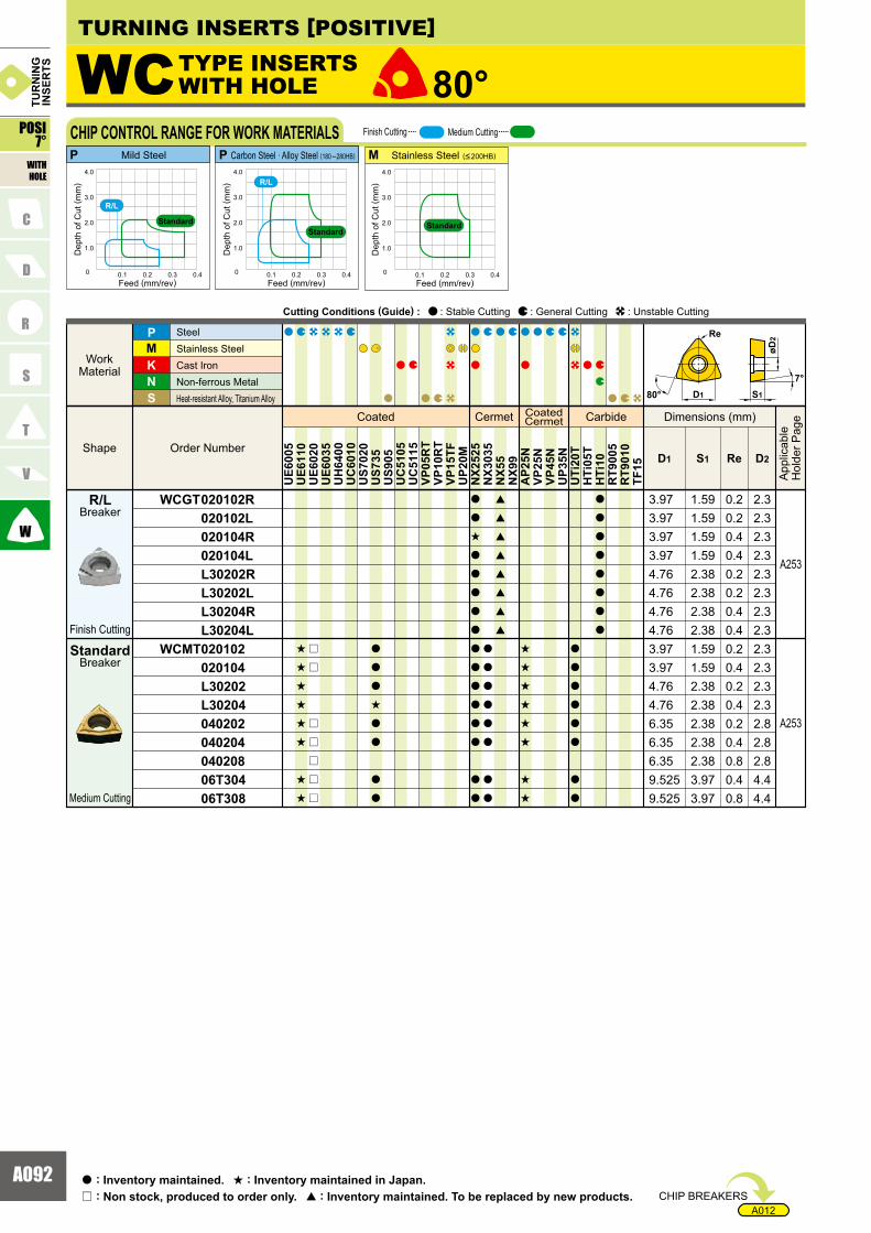
A092
A012
WCGT 020102R 020102L 020104R 020104L L30202R L30202L L30204R L30204LWCMT 020102 020104 L30202 L30204 040202 040204 040208 06T304 06T308
KNS
MP
ReD1 S1 D2
UE6
005
UE6
110
UE6
020
UE6
035
UH
6400
UC
6010
US7
020
US7
35U
S905
UC
5105
UC
5115
VP05
RT
VP10
RT
VP15
TFU
P20M
NX2
525
NX3
035
NX5
5N
X99
AP2
5NVP
25N
VP45
NU
P35N
UTi
20T
HTi
05T
HTi
10R
T900
5R
T901
0TF
15s
s
s
s
s
s
s
s
r
r
r
r
r
r
r
a
a
a
s
a
a
a
a
a
a
s
a
a
a
a
a
a
a
a
a
a
a
a
a
a
a
a
a
a
a
a
a
[
[
[
[
[
[
[
[
s
s
s
s
s
s
s
s
a
a
a
a
a
a
a
a
a
a
a
a
a
a
a
a
WC 80°
3.97 1.59 0.2 2.33.97 1.59 0.2 2.33.97 1.59 0.4 2.33.97 1.59 0.4 2.34.76 2.38 0.2 2.34.76 2.38 0.2 2.34.76 2.38 0.4 2.34.76 2.38 0.4 2.33.97 1.59 0.2 2.33.97 1.59 0.4 2.34.76 2.38 0.2 2.34.76 2.38 0.4 2.36.35 2.38 0.2 2.86.35 2.38 0.4 2.86.35 2.38 0.8 2.89.525 3.97 0.4 4.49.525 3.97 0.8 4.4
A253
A253
0 0.1 0.2 0.3 0.4
1.0
2.0
3.0
4.0
0 0.1 0.2 0.3 0.4
1.0
2.0
3.0
4.0
0 0.1 0.2 0.3 0.4
1.0
2.0
3.0
4.0
MP P
R/L
R/L
S180°7°
Re
øD2
D1
Coated Cermet CoatedCermet Carbide
Order Number Shape
Work Material
SteelStainless SteelCast Iron Non-ferrous Metal Heat-resistant Alloy, Titanium Alloy
Dimensions (mm)
App
licab
leH
olde
r Pag
e
Cutting Conditions (Guide) : : Stable Cutting : General Cutting : Unstable Cutting
WITHHOLE
TUR
NIN
GIN
SER
TS
CHIP CONTROL RANGE FOR WORK MATERIALS
Dep
th o
f Cut
( mm
)
Feed (mm/rev)
Dep
th o
f Cut
( mm
)
Feed (mm/rev)
Dep
th o
f Cut
( mm
)
Feed (mm/rev)
StandardStandard
Standard
Medium CuttingFinish Cutting
Mild Steel Carbon Steel · Alloy Steel (180 �280HB) Stainless Steel (<200HB)
TURNING INSERTS [POSITIVE]
TYPE INSERTSWITH HOLE
POSI7°
Breaker
Finish Cutting
Breaker
Medium Cutting
Standard
R/L
CHIP BREAKERS: Non stock, produced to order only.r
: Inventory maintained.a : Inventory maintained in Japan.s
: Inventory maintained. To be replaced by new products.[

A093
A002A018A013
CPMH 080204R-F 080204L-F 090304R-F 090304L-F
CPGT 080202 080204 090302 090304
CPMH 080202-SV 080204-SV 090302-SV 090304-SV 090308-SVCPMH 080204-MV 080208-MV 090304-MV 090308-MV
CPMX 080204 080208 090304 090308
A235
�
A235
A235
A235
KNS
MP
ReD1 S1 D2
UE6
005
UE6
110
UE6
020
UE6
035
UH
6400
UC
6010
US7
020
US7
35U
S905
UC
5105
UC
5115
VP05
RT
VP10
RT
VP15
TFU
P20M
NX2
525
NX3
035
NX5
5N
X99
AP2
5NVP
25N
VP45
NU
P35N
UTi
20T
HTi
05T
HTi
10R
T900
5R
T901
0TF
15
s
s
s
s
a
a
a
a
a
a
a
a
a
r
r
s
s
a
a
a
a
a
a
a
a
a
a
a
a
a
a
a
a
a
a
a
a
a
a
a
a
a
a
a
a
a
a
a
s
r
s
s
a
a
a
a
a
a
a
a
a
a
a
a
a
s
s
s
s
a
a
a
a
a
a
a
a
a
r
a
r
a
a
a
a
a
a
a
a
a
a
a
a
a
a
s
s
s
s
s
s
s
s
a
a
a
a
7.94 2.38 0.4 3.557.94 2.38 0.4 3.559.525 3.18 0.4 4.559.525 3.18 0.4 4.55
7.94 2.38 0.2 3.47.94 2.38 0.4 3.49.525 3.18 0.2 4.49.525 3.18 0.4 4.4
7.94 2.38 0.27.94 2.38 0.49.525 3.18 0.29.525 3.18 0.49.525 3.18 0.87.94 2.38 0.4 3.55
3.553.554.554.554.55
7.94 2.38 0.8 3.559.525 3.18 0.4 4.559.525 3.18 0.8 4.55
7.94 2.38 0.4 3.57.94 2.38 0.8 3.59.525 3.18 0.4 4.69.525 3.18 0.8 4.6
CP 80°
0 0.1 0.2 0.3 0.4
1.0
2.0
3.0
4.0
0 0.1 0.2 0.3 0.4
1.0
2.0
3.0
4.0
0 0.1 0.2 0.3 0.4
1.0
2.0
3.0
4.0
MP P
MV
R/L-F
SVMV
R/L-F R/L-F
MV
SV SV
11°
øD2
80° D1
ReRe
S1
Breaker
Finish Cutting
Breaker
Finish Cutting
Breaker
Light Cutting
Breaker
Medium Cutting
Breaker
Medium Cutting
Standard
Standard
R/L-F
SV
MV
Coated Cermet CoatedCermet Carbide
Order Number Shape
Work Material
SteelStainless SteelCast Iron Non-ferrous Metal Heat-resistant Alloy, Titanium Alloy
Dimensions (mm)
App
licab
leH
olde
r Pag
e
Cutting Conditions (Guide) : : Stable Cutting : General Cutting : Unstable Cutting
TUR
NIN
GIN
SER
TS
POSI11°
WITHHOLE
CHIP CONTROL RANGE FOR WORK MATERIALS
Dep
th o
f Cut
( mm
)
Feed (mm/rev)
Dep
th o
f Cut
( mm
)
Feed (mm/rev)
Dep
th o
f Cut
( mm
)
Feed (mm/rev)
Finish Cutting Light Cutting Medium Cutting
Mild Steel Carbon Steel · Alloy Steel (180 �280HB) Stainless Steel (<200HB)
TYPE INSERTSWITH HOLE
IDENTIFICATIONGRADESCHIP BREAKERS
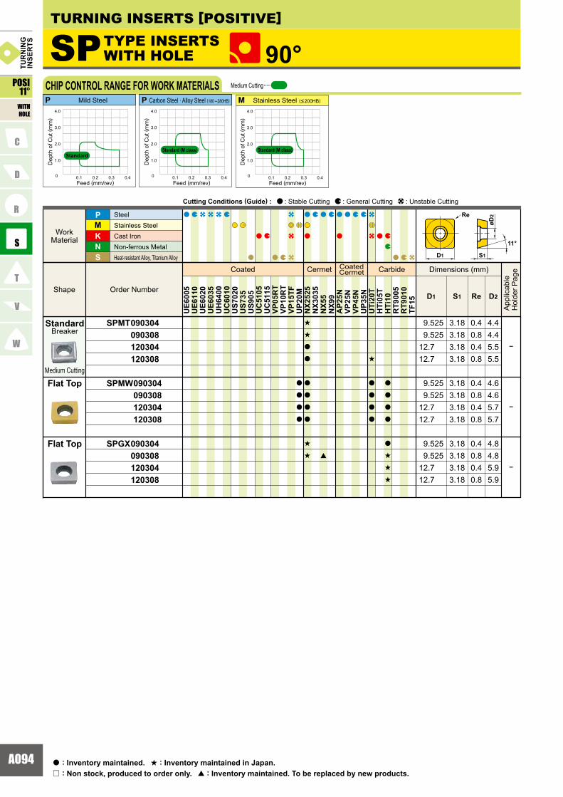
A094
SPMT 090304 090308 120304 120308
SPMW 090304 090308 120304 120308
SPGX 090304 090308 120304 120308
KNS
MP
ReD1 S1 D2
UE6
005
UE6
110
UE6
020
UE6
035
UH
6400
UC
6010
US7
020
US7
35U
S905
UC
5105
UC
5115
VP05
RT
VP10
RT
VP15
TFU
P20M
NX2
525
NX3
035
NX5
5N
X99
AP2
5NVP
25N
VP45
NU
P35N
UTi
20T
HTi
05T
HTi
10R
T900
5R
T901
0TF
15
a
a
a
a
s
s
a
a
a
a
a
a
s
s [
s
a
a
a
a
a
a
a
a
a
s
s
s
3.18 0.4 4.83.18 0.8 4.83.18 0.4 5.93.18 0.8 5.9
3.18 0.4 4.43.18 0.8 4.43.18 0.4 5.53.18 0.8 5.5
3.18 0.4 4.63.18 0.8 4.63.18 0.4 5.73.18 0.8 5.7
12.712.7
9.5259.525
12.712.7
9.5259.525
12.712.7
9.5259.525
�
�
�
90°SP
0 0.1 0.2 0.3 0.4
1.0
2.0
3.0
4.0
0 0.1 0.2 0.3 0.4
1.0
2.0
3.0
4.0
0 0.1 0.2 0.3 0.4
1.0
2.0
3.0
4.0
MP P
D1
11°
S1
øD2Re
Flat Top
Medium Cutting
Breaker
Flat Top
Standard
Coated Cermet CoatedCermet Carbide
Order NumberShape
WorkMaterial
SteelStainless Steel Cast IronNon-ferrous MetalHeat-resistant Alloy, Titanium Alloy
Dimensions (mm)
App
licab
leH
olde
r Pag
e
Cutting Conditions (Guide) : : Stable Cutting : General Cutting : Unstable Cutting
POSI11°
WITHHOLE
TURNING INSERTS [POSITIVE]TU
RN
ING
INSE
RTS
CHIP CONTROL RANGE FOR WORK MATERIALS
Dep
th o
f Cut
( mm
)
Feed (mm/rev)
Dep
th o
f Cut
( mm
)
Feed (mm/rev)
Dep
th o
f Cut
( mm
)
Feed (mm/rev)
Standard (M class)
Medium Cutting
Mild Steel Carbon Steel · Alloy Steel (180 �280HB) Stainless Steel (<200HB)
StandardStandard (M class)
TYPE INSERTSWITH HOLE
: Non stock, produced to order only.r
: Inventory maintained.a : Inventory maintained in Japan.s
: Inventory maintained. To be replaced by new products.[
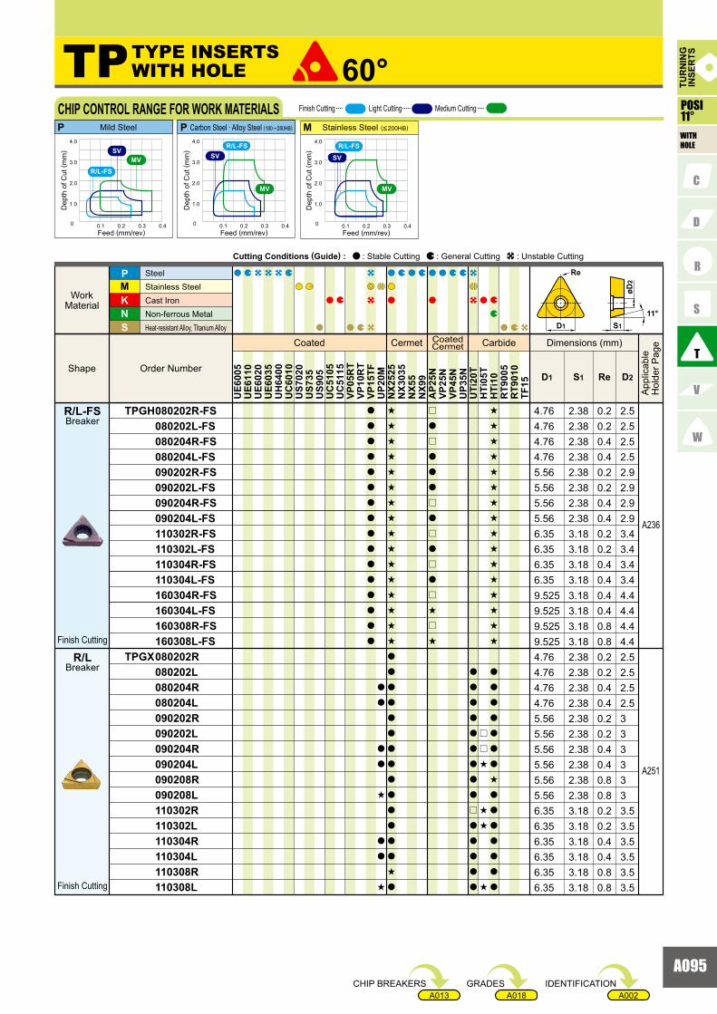
A095
A002A018A013
TPGH 080202R-FS 080202L-FS 080204R-FS 080204L-FS 090202R-FS 090202L-FS 090204R-FS 090204L-FS 110302R-FS 110302L-FS 110304R-FS 110304L-FS 160304R-FS 160304L-FS 160308R-FS 160308L-FSTPGX 080202R 080202L 080204R 080204L 090202R 090202L 090204R 090204L 090208R 090208L 110302R 110302L 110304R 110304L 110308R 110308L
A236
A251
KNS
MP
ReD1 S1 D2
UE6
005
UE6
110
UE6
020
UE6
035
UH
6400
UC
6010
US7
020
US7
35U
S905
UC
5105
UC
5115
VP05
RT
VP10
RT
VP15
TFU
P20M
NX2
525
NX3
035
NX5
5N
X99
AP2
5NVP
25N
VP45
NU
P35N
UTi
20T
HTi
05T
HTi
10R
T900
5R
T901
0TF
15
a
a
a
a
a
a
a
a
a
a
a
a
a
a
a
a
a
a
a
a
s
a
a
s
s
s
s
s
s
s
s
s
s
s
s
s
s
s
s
s
a
a
a
a
a
a
a
a
a
a
a
a
a
a
s
a
r
a
r
a
a
a
r
a
r
a
r
a
r
s
r
s
a
a
a
a
a
a
a
a
a
r
a
a
a
a
a
r
r
s
s
s
s
s
s
s
s
s
s
s
s
s
s
s
s
s
s
s
s
a
a
a
a
a
a
a
s
a
a
a
a
a
a
a
4.76 2.38 0.2 2.54.76 2.38 0.2 2.54.76 2.38 0.4 2.54.76 2.38 0.4 2.55.56 2.38 0.2 2.95.56 2.38 0.2 2.95.56 2.38 0.4 2.95.56 2.38 0.4 2.96.35 3.18 0.2 3.46.35 3.18 0.2 3.46.35 3.18 0.4 3.46.35 3.18 0.4 3.49.525 3.18 0.4 4.49.525 3.18 0.4 4.49.525 3.18 0.8 4.49.525 3.18 0.8 4.44.76 2.38 0.2 2.54.76 2.38 0.2 2.54.76 2.38 0.4 2.54.76 2.38 0.4 2.55.56 2.38 0.2 35.56 2.38 0.2 35.56 2.38 0.4 35.56 2.38 0.4 35.56 2.38 0.8 35.56 2.38 0.8 36.35 3.18 0.2 3.56.35 3.18 0.2 3.56.35 3.18 0.4 3.56.35 3.18 0.4 3.56.35 3.18 0.8 3.56.35 3.18 0.8 3.5
60°TP
0 0.1 0.2 0.3 0.4
1.0
2.0
3.0
4.0
0 0.1 0.2 0.3 0.4
1.0
2.0
3.0
4.0
0 0.1 0.2 0.3 0.4
1.0
2.0
3.0
4.0
MP P
R/L-FS
MVSV
SV
MV
R/L-FS R/L-FS
MV
SV
D1
Re
11°S1
øD2
Breaker
Finish Cutting
Breaker
Finish Cutting
R/L-FS
R/L
Coated Cermet CoatedCermet Carbide
Order Number Shape
Work Material
SteelStainless SteelCast Iron Non-ferrous Metal Heat-resistant Alloy, Titanium Alloy
Dimensions (mm)
App
licab
leH
olde
r Pag
e
Cutting Conditions (Guide) : : Stable Cutting : General Cutting : Unstable Cutting
TUR
NIN
GIN
SER
TS
POSI11°
WITHHOLE
CHIP CONTROL RANGE FOR WORK MATERIALS
Dep
th o
f Cut
( mm
)
Feed (mm/rev)
Dep
th o
f Cut
( mm
)
Feed (mm/rev)
Dep
th o
f Cut
( mm
)
Feed (mm/rev)
Finish Cutting Light Cutting Medium Cutting
Mild Steel Carbon Steel · Alloy Steel (180 �280HB) Stainless Steel (<200HB)
TYPE INSERTSWITH HOLE
IDENTIFICATIONGRADESCHIP BREAKERS

A096
KNS
MP
ReD1 S1 D2
UE6
005
UE6
110
UE6
020
UE6
035
UH
6400
UC
6010
US7
020
US7
35U
S905
UC
5105
UC
5115
VP05
RT
VP10
RT
VP15
TFU
P20M
NX2
525
NX3
035
NX5
5N
X99
AP2
5NVP
25N
VP45
NU
P35N
UTi
20T
HTi
05T
HTi
10R
T900
5R
T901
0TF
15
60°TP
TPMX 080202L 080204L 090204L 110304L
TPMH 080202-SV 080204-SV 090202-SV 090204-SV 110302-SV 110304-SV 110308-SV 160302-SV 160304-SV 160308-SVTPMH 080202-MV 080204-MV 090202-MV 090204-MV 090208-MV 110302-MV 110304-MV 110308-MV 160304-MV 160308-MVTPMX 110304 110308
a
a
a
a
a
a
a
a
a
a
a
a
a
a
a
a
a
a
a
a
a
a
a
a
a
a
a
a
a
a
a
a
a
a
a
a
a
a
a
a
a
a
a
a
a
a
a
a
a
a
a
a
a
a
a
a
a
a
a
a
a
a
a
a
a
a
a
a
a
a
a
a
a
a
a
a
a
a
r
r
s
s
a
a
a
a
a
a
a
a
a
a
a
a
a
a
a
a
a
a
a
s
s
a
a
a
a
a
a
a
a
a
a
a
a
a
a
a
a
a
a
a
a
s
s
a
a
a
a
a
a
a
a
a
a
a
a
a
a
a
a
a
a
a
a
a
a
a
a
a
a
a
a
r
4.76 2.38 0.2 2.54.76 2.38 0.4 2.55.56 2.38 0.4 3 6.35 3.14 0.4 3.5
2.52.52.92.93.43.43.44.44.44.4
4.76 2.38 0.24.76 2.38 0.45.56 2.38 0.25.56 2.38 0.46.35 3.18 0.26.35 3.18 0.46.35 3.18 0.89.525 3.18 0.29.525 3.18 0.49.525 3.18 0.8
A236
A251
A251
4.76 2.38 0.2 2.54.76 2.38 0.4 2.55.56 2.38 0.2 2.95.56 2.38 0.4 2.9
6.35 3.18 0.2 3.45.56 2.38 0.8 2.9
6.35 3.18 0.4 3.46.35 3.18 0.8 3.49.525 3.18 0.4 4.49.525 3.18 0.8 4.46.35 3.18 0.4 3.56.35 3.18 0.8 3.5
A236
0 0.1 0.2 0.3 0.4
1.0
2.0
3.0
4.0
0 0.1 0.2 0.3 0.4
1.0
2.0
3.0
4.0
0 0.1 0.2 0.3 0.4
1.0
2.0
3.0
4.0
MP P
R/L-FS
MVSV
SV
MV
R/L-FS R/L-FS
MV
SV
D1
Re
11°S1
øD2
Breaker
Medium Cutting
Breaker
Medium Cutting
Breaker
Finish Cutting
Breaker
Light Cutting
Standard
MV
L
SV
Coated Cermet CoatedCermet Carbide
Order Number Shape
Work Material
SteelStainless SteelCast Iron Non-ferrous Metal Heat-resistant Alloy, Titanium Alloy
Dimensions (mm)
App
licab
leH
olde
r Pag
e
Cutting Conditions (Guide) : : Stable Cutting : General Cutting : Unstable Cutting
CHIP CONTROL RANGE FOR WORK MATERIALS
Dep
th o
f Cut
( mm
)
Feed (mm/rev)
Dep
th o
f Cut
( mm
)
Feed (mm/rev)
Dep
th o
f Cut
( mm
)
Feed (mm/rev)
Finish Cutting Light Cutting Medium Cutting
Mild Steel Carbon Steel · Alloy Steel (180 �280HB) Stainless Steel (<200HB)
TYPE INSERTSWITH HOLE
WITHHOLE
TUR
NIN
GIN
SER
TS
POSI11°
TURNING INSERTS [POSITIVE]
: Non stock, produced to order only.r
: Inventory maintained.a : Inventory maintained in Japan.s

A097
A002A018A013
TPGX 080202 080204 080208 090202 090204 090208 110302 110304 110308 160304 160308
A251
KNS
MP
ReD1 S1 D2
s
s
s
s
s
r
a
a
a
a
a
a
a
a
a
a
a
a
a
a
r
s
s
s
a
a
a
a
a
s
a
a
a
a
a
UE6
005
UE6
110
UE6
020
UE6
035
UH
6400
UC
6010
US7
020
US7
35U
S905
UC
5105
UC
5115
VP05
RT
VP10
RT
VP15
TFU
P20M
NX2
525
NX3
035
NX5
5N
X99
AP2
5NVP
25N
VP45
NU
P35N
UTi
20T
HTi
05T
HTi
10R
T900
5R
T901
0TF
15
4.76 2.38 0.4 2.54.76 2.38 0.2 2.5
4.76 2.38 0.8 2.5
5.56 2.38 0.4 3 5.56 2.38 0.2 3
5.56 2.38 0.8 3
6.35 3.18 0.4 3.56.35 3.18 0.2 3.5
6.35 3.18 0.8 3.59.525 3.18 0.4 4.89.525 3.18 0.8 4.8
D1
Re
11°S1
øD2
TUR
NIN
GIN
SER
TS
Coated Cermet CoatedCermet Carbide
Order NumberShape
WorkMaterial
SteelStainless Steel Cast IronNon-ferrous MetalHeat-resistant Alloy, Titanium Alloy
Dimensions (mm)
App
licab
leH
olde
r Pag
e
Cutting Conditions (Guide) : : Stable Cutting : General Cutting : Unstable Cutting
WITHHOLE
Flat Top
POSI11°
IDENTIFICATIONGRADESCHIP BREAKERS

A098
A013
WPGT 040202R-FS 040202L-FS 040204R-FS 040204L-FS 060304R-FS 060304L-FS 060308R-FS 060308L-FSWPGT 040202 040204 060302 060304
WPMT 040202-MV 040204-MV 060304-MV 060308-MV
KNS
MP
ReD1 S1 D2
UE6
005
UE6
110
UE6
020
UE6
035
UH
6400
UC
6010
US7
020
US7
35U
S905
UC
5105
UC
5115
VP05
RT
VP10
RT
VP15
TFU
P20M
NX2
525
NX3
035
NX5
5N
X99
AP2
5NVP
25N
VP45
NU
P35N
UTi
20T
HTi
05T
HTi
10R
T900
5R
T901
0TF
15
a
a
a
a
a
a
a
a
a
a
a
a
a
a
a
a
a
a
a
a
a
a
a
a
s
s
s
s
s
s
s
s
a
a
a
a
a
a
a
a
r
r
r
r
r
r
r
r
r
r
r
r
a
a
a
a
s
s
s
s
s
s
s
s
a
a
a
a
6.35 2.38 0.2 2.86.35 2.38 0.2 2.86.35 2.38 0.4 2.86.35 2.38 0.4 2.89.525 3.18 0.4 4.49.525 3.18 0.4 4.49.525 3.18 0.8 4.49.525 3.18 0.8 4.46.35 2.38 0.2 2.86.35 2.38 0.4 2.89.525 3.18 0.2 4.49.525 3.18 0.4 4.4
6.35 2.38 0.2 2.86.35 2.38 0.4 2.89.525 3.18 0.4 4.49.525 3.18 0.8 4.4
A239
A239
A239
80°WP
0 0.1 0.2 0.3 0.4
1.0
2.0
3.0
4.0
0 0.1 0.2 0.3 0.4
1.0
2.0
3.0
4.0
0 0.1 0.2 0.3 0.4
1.0
2.0
3.0
4.0
MP P
MV
R/L-FS
MV
R/L-FS
MV
R/L-FS
S1
11°
øD2
D1
Re
80°
Breaker
Finish Cutting
Breaker
Medium Cutting
Breaker
Finish Cutting
Standard
MV
R/L-FS
Coated Cermet CoatedCermet Carbide
Order Number Shape
Work Material
SteelStainless SteelCast Iron Non-ferrous Metal Heat-resistant Alloy, Titanium Alloy
Dimensions (mm)
App
licab
leH
olde
r Pag
e
Cutting Conditions (Guide) : : Stable Cutting : General Cutting : Unstable Cutting
WITHHOLE
TURNING INSERTS [POSITIVE]TU
RN
ING
INSE
RTS
CHIP CONTROL RANGE FOR WORK MATERIALS
Dep
th o
f Cut
( mm
)
Feed (mm/rev)
Dep
th o
f Cut
( mm
)
Feed (mm/rev)
Dep
th o
f Cut
( mm
)
Feed (mm/rev)
Finish Cutting Medium Cutting
Mild Steel Carbon Steel · Alloy Steel (180 �280HB) Stainless Steel (<200HB)
TYPE INSERTSWITH HOLE
POSI11°
: Non stock, produced to order only.r
: Inventory maintained.a : Inventory maintained in Japan.s
CHIP BREAKERS
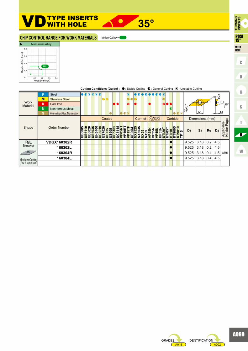
A099
A002A018
VDGX 160302R 160302L 160304R 160304L
KNS
MP
ReD1 S1 D2
UE6
005
UE6
110
UE6
020
UE6
035
UH
6400
UC
6010
US7
020
US7
35U
S905
UC
5105
UC
5115
VP05
RT
VP10
RT
VP15
TFU
P20M
NX2
525
NX3
035
NX5
5N
X99
AP2
5NVP
25N
VP45
NU
P35N
UTi
20T
HTi
05T
HTi
10R
T900
5R
T901
0TF
15
a
a
a
a
9.525 3.18 0.2 4.59.525 3.18 0.2 4.59.525 3.18 0.4 4.59.525 3.18 0.4 4.5
A194
35°VD
0 0.1 0.2 0.3 0.4
1.0
2.0
3.0
4.0
N
R/L
15°
øD2
D1 S1
Re
35°
Breaker
Medium Cutting(For Aluminium)
R/L
Coated Cermet CoatedCermet Carbide
Order Number Shape
Work Material
SteelStainless SteelCast Iron Non-ferrous Metal Heat-resistant Alloy, Titanium Alloy
Dimensions (mm)
App
licab
leH
olde
r Pag
e
Cutting Conditions (Guide) : : Stable Cutting : General Cutting : Unstable Cutting
TUR
NIN
GIN
SER
TS
WITHHOLE
CHIP CONTROL RANGE FOR WORK MATERIALS
Dep
th o
f Cut
( mm
)
Feed (mm/rev)
Aluminium Alloy
Medium Cutting
TYPE INSERTSWITH HOLE
POSI15°
IDENTIFICATIONGRADES

A100
DEGX 150402R-F 150402L-F 150404R-F 150404L-F
DEGX 150402R 150402L 150404R 150404L
A192
A192
KNS
MP
ReD1 S1 D2
UE6
005
UE6
110
UE6
020
UE6
035
UH
6400
UC
6010
US7
020
US7
35U
S905
UC
5105
UC
5115
VP05
RT
VP10
RT
VP15
TFU
P20M
NX2
525
NX3
035
NX5
5N
X99
AP2
5NVP
25N
VP45
NU
P35N
UTi
20T
HTi
05T
HTi
10R
T900
5R
T901
0TF
15
a
a
s
s
a
a
a
a
12.7 4.76 0.2 5.112.7 4.76 0.2 5.112.7 4.76 0.4 5.112.7 4.76 0.4 5.1
12.7 4.76 0.2 5.112.7 4.76 0.2 5.112.7 4.76 0.4 5.112.7 4.76 0.4 5.1
55°DE
0 0.1 0.2 0.3 0.4
1.0
2.0
3.0
4.0
N
R/L
R/L-F
55°
20°
øD2
D1 S1
Re
Breaker
Finish Cutting(For Aluminium)
Breaker
Medium Cutting(For Aluminium)
R/L-F
R/L
Coated Cermet CoatedCermet Carbide
Order Number Shape
Work Material
SteelStainless SteelCast Iron Non-ferrous Metal Heat-resistant Alloy, Titanium Alloy
Dimensions (mm)
App
licab
leH
olde
r Pag
e
Cutting Conditions (Guide) : : Stable Cutting : General Cutting : Unstable Cutting
WITHHOLE
TUR
NIN
GIN
SER
TS
CHIP CONTROL RANGE FOR WORK MATERIALS
Dep
th o
f Cut
( mm
)
Feed (mm/rev)
Aluminium Alloy
Finish Cutting Medium Cutting
TURNING INSERTS [POSITIVE]
TYPE INSERTSWITH HOLE
POSI20°
: Inventory maintained.a : Inventory maintained in Japan.s
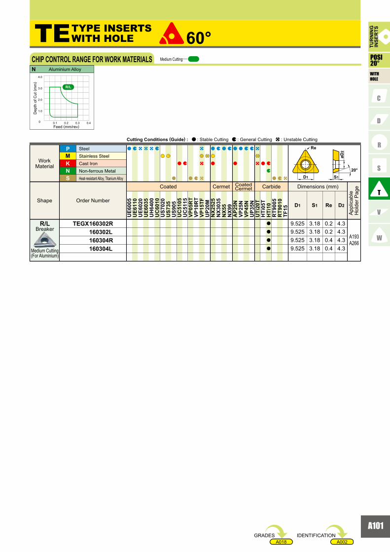
A101
A002A018
TEGX 160302R 160302L 160304R 160304L
A193A266
KNS
MP
ReD1 S1 D2
UE6
005
UE6
110
UE6
020
UE6
035
UH
6400
UC
6010
US7
020
US7
35U
S905
UC
5105
UC
5115
VP05
RT
VP10
RT
VP15
TFU
P20M
NX2
525
NX3
035
NX5
5N
X99
AP2
5NVP
25N
VP45
NU
P35N
UTi
20T
HTi
05T
HTi
10R
T900
5R
T901
0TF
15
a
a
a
a
9.525 3.18 0.2 4.39.525 3.18 0.2 4.39.525 3.18 0.4 4.39.525 3.18 0.4 4.3
60°TE
0 0.1 0.2 0.3 0.4
1.0
2.0
3.0
4.0
N
R/L
20°D1
Re
S1
øD2
Breaker
Medium Cutting(For Aluminium)
R/L
Coated Cermet CoatedCermet Carbide
Order Number Shape
Work Material
SteelStainless SteelCast Iron Non-ferrous Metal Heat-resistant Alloy, Titanium Alloy
Dimensions (mm)
App
licab
leH
olde
r Pag
e
Cutting Conditions (Guide) : : Stable Cutting : General Cutting : Unstable Cutting
TUR
NIN
GIN
SER
TS
WITHHOLE
CHIP CONTROL RANGE FOR WORK MATERIALS
Dep
th o
f Cut
( mm
)
Feed (mm/rev)
Aluminium Alloy
Medium Cutting
TYPE INSERTSWITH HOLE
POSI20°
IDENTIFICATIONGRADES

A102
RDGH 120400-M4
KNS
MP
D1 S1 D2U
E600
5U
E611
0U
E602
0U
E603
5U
H64
00U
C60
10U
S702
0U
S735
US9
05U
C51
05U
C51
15VP
05R
TVP
10R
TVP
15TF
UP2
0MN
X252
5N
X303
5N
X55
NX9
9A
P25N
VP25
NVP
45N
UP3
5NU
Ti20
TH
Ti05
TH
Ti10
RT9
005
RT9
010
TF15
s s 12.7 4.76 4.5
A195
RD
D1 S1
15°
øD2
Breaker
For Special Use(For Rotary Tools)
M4
Coated Cermet CoatedCermet Carbide
Order NumberShape
WorkMaterial
SteelStainless Steel Cast IronNon-ferrous MetalHeat-resistant Alloy, Titanium Alloy
Dimensions (mm)
App
licab
leH
olde
r Pag
e
Cutting Conditions (Guide) : : Stable Cutting : General Cutting : Unstable Cutting
TURNING INSERTS [POSITIVE]
TYPE INSERTSWITH HOLE
: Inventory maintained.a : Inventory maintained in Japan.s
WITHHOLE
TUR
NIN
GIN
SER
TS
POSI15°

A103
A002A018
RGGM 2004M0
�
KNS
MP
D1 S1 D2U
E600
5U
E611
0U
E602
0U
E603
5U
H64
00U
C60
10U
S702
0U
S735
US9
05U
C51
05U
C51
15VP
05R
TVP
10R
TVP
15TF
UP2
0MN
X252
5N
X303
5N
X55
NX9
9A
P25N
VP25
NVP
45N
UP3
5NU
Ti20
TH
Ti05
TH
Ti10
RT9
005
RT9
010
TF15
a 20 4.76 5.6
RG
30°
D1
øD2
S1
Coated Cermet CoatedCermet Carbide
Order NumberShape
WorkMaterial
SteelStainless Steel Cast IronNon-ferrous MetalHeat-resistant Alloy, Titanium Alloy
Dimensions (mm)
App
licab
leH
olde
r Pag
e
Cutting Conditions (Guide) : : Stable Cutting : General Cutting : Unstable Cutting
(For General Cutting)
TYPE INSERTSWITH HOLE
BreakerStandard
IDENTIFICATIONGRADES
TUR
NIN
GIN
SER
TS
WITHHOLE
POSI30°

A104
SPMR 090304 090308 120304 120308 120312SPMR 090304-80 090308-80 120308-80 120312-80
SPMN 090304 090308 120304 120304T 120308 120308T 120312 120320 120408 120412 150408 150412 190404 190408 190412 190416 250616
KNS
MP
ReD1 S1
UE6
005
UE6
110
UE6
020
UE6
035
UH
6400
UC
6010
US7
020
US7
35U
S905
UC
5105
UC
5115
VP05
RT
VP10
RT
VP15
TFU
P20M
NX2
525
NX3
035
NX5
5N
X99
AP2
5NVP
25N
VP45
NU
P35N
UTi
20T
HTi
05T
HTi
10R
T900
5R
T901
0TF
15
a
a
a
a
a
a
a
a
a
a
a
s
s
s
s
s
r
r
s
s
r
r
[
[
[
[
[
[
[
[
[
[
[
[
[
[
a a
a
r
s
r
r
r
s
r
r
s
a
a
a
s
s
a
s
a
a
a
[
[
[
[
[
[
[
[
[
[
[
[
a
a
a
a
a
a
a
a
a
a
a
s
a
a
a
a
a
a
s
a
a
a
a
s
90°SP
3.18 0.43.18 0.83.18 0.43.18 0.83.18 1.2
3.18 0.43.18 0.83.18 0.4
3.18 0.8
3.18 1.2
4.76 0.84.76 1.2
15.875 4.76 0.815.875 4.76 1.2
4.76 0.44.76 0.84.76 1.24.76 1.6
12.7
12.7
12.712.7
9.525
12.73.18 0.812.7
12.73.18 0.412.7
9.525
12.7
12.79.5259.525
3.18 0.43.18 0.83.18 0.83.18 1.212.7
12.79.5259.525
19.0519.05
19.0519.05
3.18 2.012.7
6.35 1.625.40
�
�
�
0 0.1 0.2 0.3 0.4
1.0
2.0
3.0
4.0
0 0.1 0.2 0.3 0.4
1.0
2.0
3.0
4.0
P P
11°
S1D1
Re
Coated Cermet CoatedCermet Carbide
Order Number Shape
Work Material
SteelStainless SteelCast Iron Non-ferrous Metal Heat-resistant Alloy, Titanium Alloy
Dimensions (mm)
App
licab
leH
olde
r Pag
e
Cutting Conditions (Guide) : : Stable Cutting : General Cutting : Unstable Cutting
TUR
NIN
GIN
SER
TS
CHIP CONTROL RANGE FOR WORK MATERIALS
Dep
th o
f Cut
( mm
)
Feed (mm/rev)
Dep
th o
f Cut
( mm
)
Feed (mm/rev)
Finish Cutting Medium Cutting
Mild Steel Carbon Steel · Alloy Steel (180 �280HB)
R/L(G class)R/L(G class)Standard(M class)
Standard(M class)
TURNING INSERTS [POSITIVE]
TYPE INSERTSWITHOUT HOLE
POSI11°
Breaker
Light toMedium Cutting
Breaker
Light toMedium Cutting
Flat Top
Standard
80
: Non stock, produced to order only.r
: Inventory maintained.a : Inventory maintained in Japan.s
: Inventory maintained. To be replaced by new products.[
WITHOUTHOLE

A105
A002A018
SPGN 090304 090308 120304 120308 120312 120404 120408 150404 150408 190402 190404 190408
KNS
MP
ReD1 S1
s
s
r
a
s
s
[
[
[
a
a
a
a
a
a
a
a
a
a
s
a
a
a
a
s
s
s
a
UE6
005
UE6
110
UE6
020
UE6
035
UH
6400
UC
6010
US7
020
US7
35U
S905
UC
5105
UC
5115
VP05
RT
VP10
RT
VP15
TFU
P20M
NX2
525
NX3
035
NX5
5N
X99
AP2
5NVP
25N
VP45
NU
P35N
UTi
20T
HTi
05T
HTi
10R
T900
5R
T901
0TF
15
3.18 0.43.18 0.83.18 0.43.18 0.83.18 1.24.76 0.44.76 0.8
15.875 4.76 0.415.875 4.76 0.8
4.76 0.24.76 0.44.76 0.8
9.525
12.712.712.7
12.712.7
9.525
19.0519.0519.05
�
11°
S1D1
Re
TUR
NIN
GIN
SER
TS
Coated Cermet CoatedCermet Carbide
Order NumberShape
WorkMaterial
SteelStainless Steel Cast IronNon-ferrous MetalHeat-resistant Alloy, Titanium Alloy
Dimensions (mm)
App
licab
leH
olde
r Pag
e
Cutting Conditions (Guide) : : Stable Cutting : General Cutting : Unstable Cutting
POSI11°
WITHOUTHOLE
IDENTIFICATIONGRADES
Flat Top

A106
TPGR 110304R 110304L 160304R 160304L 160308R 160308LTPMR 090202 090204 090208 110302 110304 110308 160304 160308 160312TPMR 110304-80 110308-80 160304-80 160308-80
TPMN 110204 110208 110304 110308 110312 160304 160304T 160308 160308T 160312 160312T 160316 160320
KNS
MP
ReD1 S1
UE6
005
UE6
110
UE6
020
UE6
035
UH
6400
UC
6010
US7
020
US7
35U
S905
UC
5105
UC
5115
VP05
RT
VP10
RT
VP15
TFU
P20M
NX2
525
NX3
035
NX5
5N
X99
AP2
5NVP
25N
VP45
NU
P35N
UTi
20T
HTi
05T
HTi
10R
T900
5R
T901
0TF
15
a
a
a
a
a
a
a
a
a
a
a
a
a
a
a
a
a
s
a
a
s
r
r
r
s
s
a
a
s
r
r
r
r
r
r
s
r
r
r
[
[
[
[
[
[
[
[
[
[
[
[
[
s
[
[
a
a
a
a
a
a
a
a
a
r
r
r
a
r
r
a
a
a
a
a
a
a
a
a
a
a
s
a
a
s
s
a
s
a
a
a
a
a
a
a
s
a
a
a
a
s
s
[
[
[
[
[
[
[
a
a
s
a
s
a
a
a
a
a
a
a
a
a
r
a
a
a
a
a
s
a
a
s
a
s
a
a
a
a
a
60°TP
3.18 0.43.18 0.43.18 0.43.18 0.43.18 0.83.18 0.82.38 0.22.38 0.42.38 0.83.18 0.23.18 0.43.18 0.83.18 0.43.18 0.83.18 1.2
3.18 0.43.18 0.83.18 1.23.18 0.4
3.18 0.8
3.18 1.2
3.18 1.63.18 2.0
5.56
6.35
9.525
9.5259.525
3.18 1.29.525
9.5253.18 0.89.525
9.5253.18 0.49.525
6.356.35
2.38 0.42.38 0.86.35
6.35
9.5259.525
9.525
6.356.356.35
3.18 0.43.18 0.83.18 0.43.18 0.89.525
9.525
6.356.35
5.565.56
6.35
9.525
9.5259.525
9.5256.35
A252
A252
A252
A252
0 0.1 0.2 0.3 0.4
1.0
2.0
3.0
4.0
0 0.1 0.2 0.3 0.4
1.0
2.0
3.0
4.0
P P
11°
Re
S1D1
Coated Cermet CoatedCermet Carbide
Order NumberShape
WorkMaterial
SteelStainless Steel Cast IronNon-ferrous MetalHeat-resistant Alloy, Titanium Alloy
Dimensions (mm)
App
licab
leH
olde
r Pag
e
Cutting Conditions (Guide) : : Stable Cutting : General Cutting : Unstable Cutting
TUR
NIN
GIN
SER
TS
POSI11°
WITHOUTHOLE
CHIP CONTROL RANGE FOR WORK MATERIALS
Dep
th o
f Cut
( mm
)
Feed (mm/rev)
Dep
th o
f Cut
( mm
)
Feed (mm/rev)
Finish Cutting Medium Cutting
Mild Steel Carbon Steel · Alloy Steel (180 �280HB)
R/L(G class)R/L(G class)
Standard(M class)Standard(M class)
TURNING INSERTS [POSITIVE]
TYPE INSERTSWITHOUT HOLE
Breaker
Finish Cutting
Breaker
Breaker
Light toMedium Cutting
Light toMedium Cutting
Flat Top
Standard
R/L
80
: Non stock, produced to order only.r
: Inventory maintained.a : Inventory maintained in Japan.s
: Inventory maintained. To be replaced by new products.[

A107
A002A018
TPMN 160408 220404 220408 220412 220416 220420TPGN 110302 110304 110308 160302 160304 160308 160312 160316 160404 160408 220404 220408 220412
KNS
MP
ReD1 S1
a
s
s
s
s
s
s
s
r
s
s
s r r
r
a
r
r
s
s
s
s
s
s
s
s
a
s
s
r
[
[
a
a
a
a
a
s
a
a
a
s
s
s
r
a
a
a
a
s
s
s
s
a
a
a
a
a
a
a
a
a
s
a
a
a
UE6
005
UE6
110
UE6
020
UE6
035
UH
6400
UC
6010
US7
020
US7
35U
S905
UC
5105
UC
5115
VP05
RT
VP10
RT
VP15
TFU
P20M
NX2
525
NX3
035
NX5
5N
X99
AP2
5NVP
25N
VP45
NU
P35N
UTi
20T
HTi
05T
HTi
10R
T900
5R
T901
0TF
15
4.76 0.84.76 0.44.76 0.84.76 1.24.76 1.64.76 2.0
9.525
12.712.7
12.7
12.712.7
3.18 0.23.18 0.43.18 0.83.18 0.23.18 0.43.18 0.83.18 1.23.18 1.64.76 0.44.76 0.84.76 0.44.76 0.84.76 1.2
9.525
12.712.7
12.79.525
9.5259.525
9.525
9.5259.525
6.35
6.35 6.35
A252
A252
11°
Re
S1D1
TUR
NIN
GIN
SER
TS
Coated Cermet CoatedCermet Carbide
Order NumberShape
WorkMaterial
SteelStainless Steel Cast IronNon-ferrous MetalHeat-resistant Alloy, Titanium Alloy
Dimensions (mm)
App
licab
leH
olde
r Pag
e
Cutting Conditions (Guide) : : Stable Cutting : General Cutting : Unstable Cutting
POSI11°
WITHOUTHOLE
IDENTIFICATIONGRADES
Flat Top
Flat Top

A108
A002A018
RTG 05A 06A 07A 08A 10A 12A
KN
MP
D4D1 L2 L5U
E600
5U
E611
0U
E602
0U
E603
5U
H64
00U
C60
10U
S702
0U
S735
US9
05U
C51
05U
C51
15VP
05R
TVP
10R
TVP
15TF
UP2
0MN
X252
5N
X303
5N
X55
NX9
9A
P25N
VP25
NVP
45N
UP3
5NU
Ti20
TH
Ti05
TH
Ti10
RT9
005
RT9
010
TF15
a
a
a
a
a
a
a
a
a
a
a
a
RTG
A196
5 2.5 3.56 3.5 3.57 11 3.5 58 4.5 5
10 5.5 6.512
7.5 7.511111414 7.5 6.5
6° 15°
L2
øD1
L5
øD412°
Coated Cermet CoatedCermet Carbide
Order NumberShape
WorkMaterial
Steel
Stainless Steel
Cast Iron
Non-ferrous Metal
Dimensions (mm)
App
licab
leH
olde
r Pag
e
Cutting Conditions (Guide) : : Stable Cutting : General Cutting : Unstable Cutting
TUR
NIN
GIN
SER
TSTURNING INSERTS [POSITIVE]
TYPE INSERTSWITHOUT HOLE
POSI6°
WITHOUTHOLE (Tangent Angle)
Special Purpose(For TL Holder)
: Inventory maintained.a IDENTIFICATIONGRADES

A109
Memo