Embed Size (px)
Citation preview

Control Panel Technical GuideHow to reduce damage to components through effective thermal management

2
To find out moreabout thermal management
solutions for control enclosures,
please consult our catalogue
or visit our website at
www.schneider-electric.com

3
ContentsIntroduction 4 to 7
1 Analysis of thermal conditions 8 to 13
• Internalanalyses • Externalanalyses
2 Thermal optimisation solutions
•Overview 14to15 • "Passive"solutions 16to26 • "Active"solutions 27to55
3 Practical summary 58to61
4 Guide for choosing thermal optimisation solutions 62to69

4
All the expertise of Schneider Electric devoted to the thermal management of your enclosures
Many of our customers, including design and engineering departments, panel builders, integrators or even OEMs, ask us to help them optimise the performance of their electrical installations, while complying with environmental constraints and avoiding thermal problems.
Schneider Electric, as a leading international specialist in energy-efficiency management, has drawn up this expert's operating guide for these customers (and any others).
Through this overall fully practical and comprehensive document, Schneider Electric wants to share all its experience in thermal management of electric enclosures with its customers.

5
All the expertise of Schneider Electric devoted to the thermal management of your enclosures
ConsequencesEven the slightest shut-down or malfunction of the electrical installation can have major – even catastrophic – financial repercussions for a company, regardless of its business sector.
Here are some examples of business sectors in which 1 hour of down time can be very expensive:
Motor industry ¤ 10,000Agri-business industry
¤ 6,000
Microprocessor industry
¤ 35,600,000
Banking transaction services
¤ 2,940,000
Airline ticket-booking services
¤ 90,000
Mobile telephone operators
¤ 47,000
SMEs¤ 350
Reasons why installations shut down or malfunction
In the vast majority of cases, when electric installations and devices housed in control enclosures shut down or malfunction, the problem is thermal: excessively high or low temperature of electrical and, especially, electronic equipment.
Uncontrolled external climatic conditions
Internal heat balance not calculated
Pollution and difficult or harsh environmental conditions
High likelihood of a breakdown or malfunction of the installation
NB.: Total financial losses depend on the size of the affected manufacturing process.
Metalworking (foundry) ¤ 50,000Glassworks ¤ 40,000

6
Thermal management issues inside and outside your enclosures
Avoiding down-timeandmalfunctions causedbyoverheating ofelectricalandelectronicdevices
Extending theservicelife oftheinternalcomponents
Reducing •costsassociated withthemanufacturingprocesses
•maintenance cyclesandcosts fortheinstallation
Guaranteeing continuityofservice
7
Reducing •costsassociated withthemanufacturingprocesses
•maintenance cyclesandcosts fortheinstallation
Guaranteeing continuityofservice
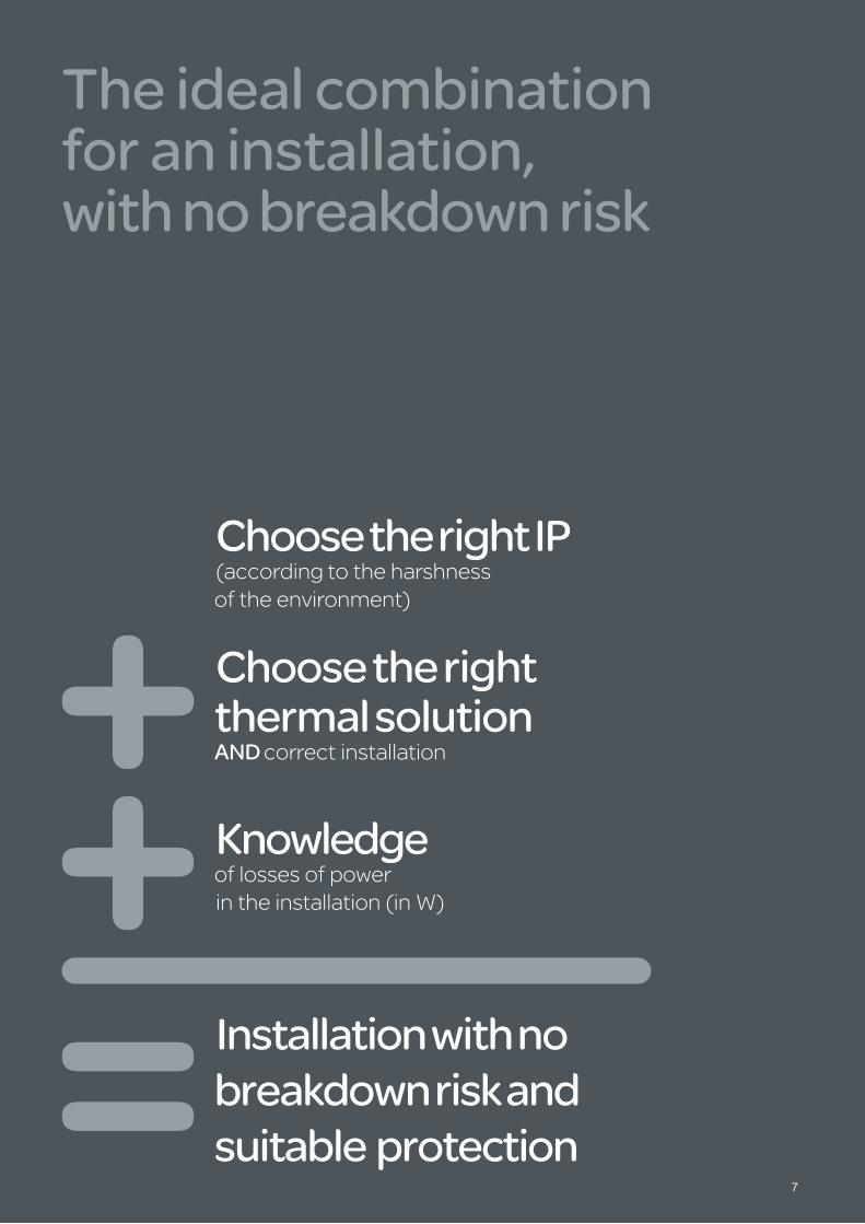
The ideal combination for an installation, with no breakdown risk
Choose the right IP(accordingtotheharshness oftheenvironment)
Choose the right thermal solution And correctinstallation
Knowledge oflossesofpowerintheinstallation(inW)
Installation with no breakdown risk and suitable protection

18
Analysis of thermal conditions
Control Panel - Technical Guide • Howtoreducedamagetocomponentsthrougheffectivethermalmanagement
9
Analysis of thermal conditions
Internal analyses• Analysis of thermal conditions inside the enclosure
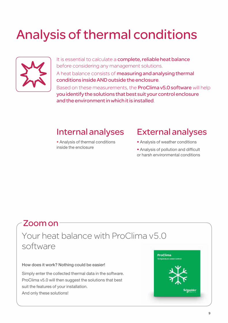
Itisessentialtocalculateacomplete, reliable heat balance beforeconsideringanymanagementsolutions.
Aheatbalanceconsistsofmeasuring and analysing thermal conditions inside And outside the enclosure.Basedonthesemeasurements,theProClima v5.0 softwarewillhelpyou identify the solutions that best suit your control enclosure and the environment in which it is installed.
Zoom onYourheatbalancewithProClimav5.0 software
How does it work? Nothing could be easier!
Simply enter the collected thermal data in the software.
ProClima v5.0 will then suggest the solutions that best
suit the features of your installation.
And only these solutions!
External analyses• Analysis of weather conditions
• Analysis of pollution and difficult or harsh environmental conditions
10
Control Panel - Technical Guide • Howtoreducedamagetocomponentsthrougheffectivethermalmanagement
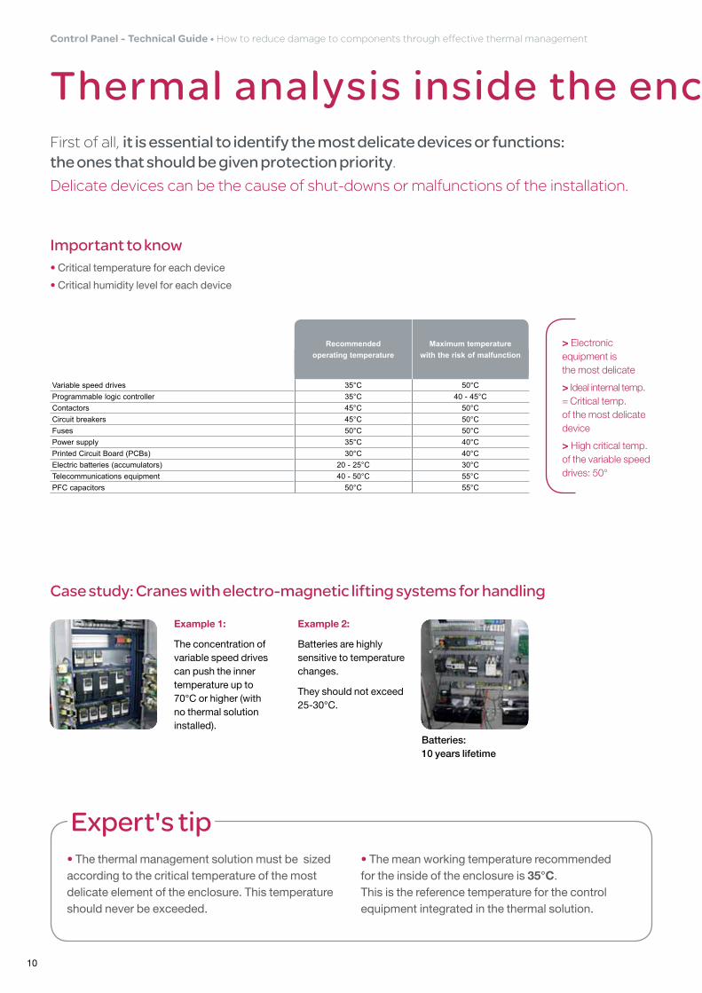
Thermal analysis inside the enclosureFirstofall,it is essential to identify the most delicate devices or functions: the ones that should be given protection priority.Delicatedevicescanbethecauseofshut-downsormalfunctionsoftheinstallation.
Important to know• Critical temperature for each device
• Critical humidity level for each device
> Electronic equipment is the most delicate
> Ideal internal temp. = Critical temp. of the most delicate device
> High critical temp. of the variable speed drives: 50°
Expert's tip• The thermal management solution must be sized according to the critical temperature of the most delicate element of the enclosure. This temperature should never be exceeded.
• The mean working temperature recommended for the inside of the enclosure is 35°C. This is the reference temperature for the control equipment integrated in the thermal solution.
Recommended operating temperature
Maximum temperature with the risk of malfunction
Variable speed drives 35°C 50°CProgrammable logic controller 35°C 40 - 45°CContactors 45°C 50°CCircuit breakers 45°C 50°CFuses 50°C 50°CPower supply 35°C 40°CPrinted Circuit Board (PCBs) 30°C 40°CElectric batteries (accumulators) 20 - 25°C 30°CTelecommunications equipment 40 - 50°C 55°CPFC capacitors 50°C 55°C
Example 1:
The concentration of variable speed drives can push the inner temperature up to 70°C or higher (with no thermal solution installed).
Example 2:
Batteries are highly sensitive to temperature changes.
They should not exceed 25-30°C.
Case study: Cranes with electro-magnetic lifting systems for handling
Batteries: 10 years lifetime
11
Analysis of thermal conditions
Thermal analysis inside the enclosure
Measuring the air temperature1
Measuring losses of power (W)2
The measurement of air temperature inside the enclosure, mustbetakenover a complete period (e.g.:oneproductioncycle,24hours,1week,etc.).
This data will be used:> To complete the overall thermal analysis
> To avoid exceeding the critical temperature of each device
> To calculate the loss of power (W) of each device
Beforeperformingthethermalcalculation,itisimportanttohavedetailedinformationofthe dissipation value of each component.Generallyspeaking,thisvalueisnot easy to find.
Expert's tipUse the ProClima v5.0 software to find out the dissipation value of the components
in your enclosure. ProClima v5.0 offers the loss values for all the most common
devices on the market.
Expert's tipThe temperature measurement inside the enclosure should be taken in three separate areas (T1, T2 and T3). Avoid the ventilated hot-air outlet.
The hot-air ventilation flows affect the temperature in the various areas.
Also, each case must be studied separately and in detail.
Mean temp. of the enclosure = (T1 + T2 + T3) / 3.
12
Control Panel - Technical Guide • Howtoreducedamagetocomponentsthrougheffectivethermalmanagement
Analysis of weather conditions
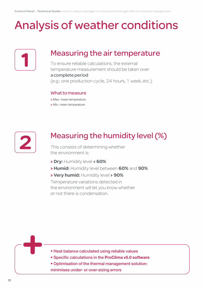
Measuring the air temperature1What to measure> Max. mean temperature
> Min. mean temperature
Toensurereliablecalculations,theexternaltemperaturemeasurementshouldbetakenover a complete period (e.g.:oneproductioncycle,24hours,1week,etc.).
Measuring the humidity level (%)2 Thisconsistsofdeterminingwhether theenvironmentis:
> Dry: Humiditylevel< 60%
> Humid: Humiditylevelbetween60%and90%
> Very humid:Humiditylevel> 90%Temperaturevariationsdetectedin theenvironmentwillletyouknowwhether ornotthereiscondensation.
• Heat balance calculated using reliable values
• Specific calculations in the ProClima v5.0 software
• Optimisation of the thermal management solution:
minimises under- or over-sizing errors
13
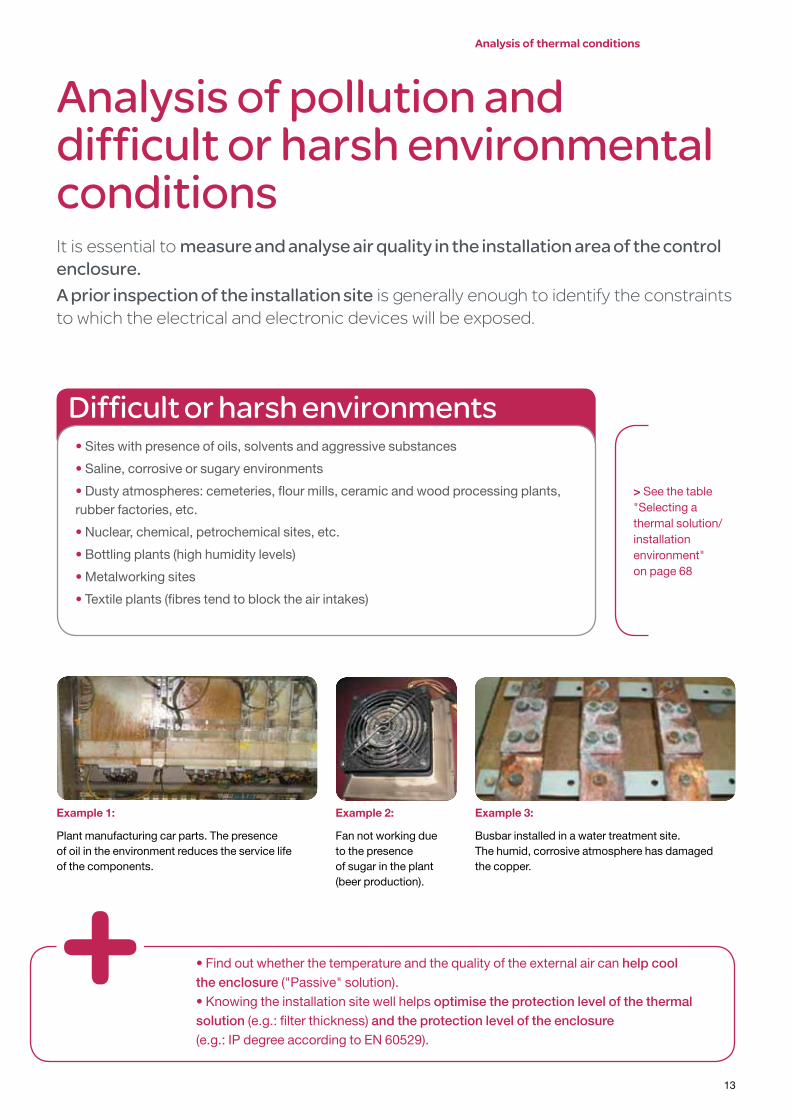
Analysis of pollution and difficult or harsh environmental conditionsItisessentialtomeasure and analyse air quality in the installation area of the control enclosure.A prior inspection of the installation siteisgenerallyenoughtoidentifytheconstraintstowhichtheelectricalandelectronicdeviceswillbeexposed.
• Find out whether the temperature and the quality of the external air can help cool the enclosure ("Passive" solution).• Knowing the installation site well helps optimise the protection level of the thermal solution (e.g.: filter thickness) and the protection level of the enclosure (e.g.: IP degree according to EN 60529).
difficult or harsh environments• Sites with presence of oils, solvents and aggressive substances
• Saline, corrosive or sugary environments
• Dusty atmospheres: cemeteries, flour mills, ceramic and wood processing plants, rubber factories, etc.
• Nuclear, chemical, petrochemical sites, etc.
• Bottling plants (high humidity levels)
• Metalworking sites
• Textile plants (fibres tend to block the air intakes)
> See the table "Selecting a thermal solution/installation environment" on page 68
Example 1:
Plant manufacturing car parts. The presence of oil in the environment reduces the service life of the components.
Example 2:
Fan not working due to the presence of sugar in the plant (beer production).
Example 3:
Busbar installed in a water treatment site. The humid, corrosive atmosphere has damaged the copper.
Analysis of thermal conditions

214
Thermal optimisation
solutions
Control Panel - Technical Guide • Howtoreducedamagetocomponentsthrougheffectivethermalmanagement
15
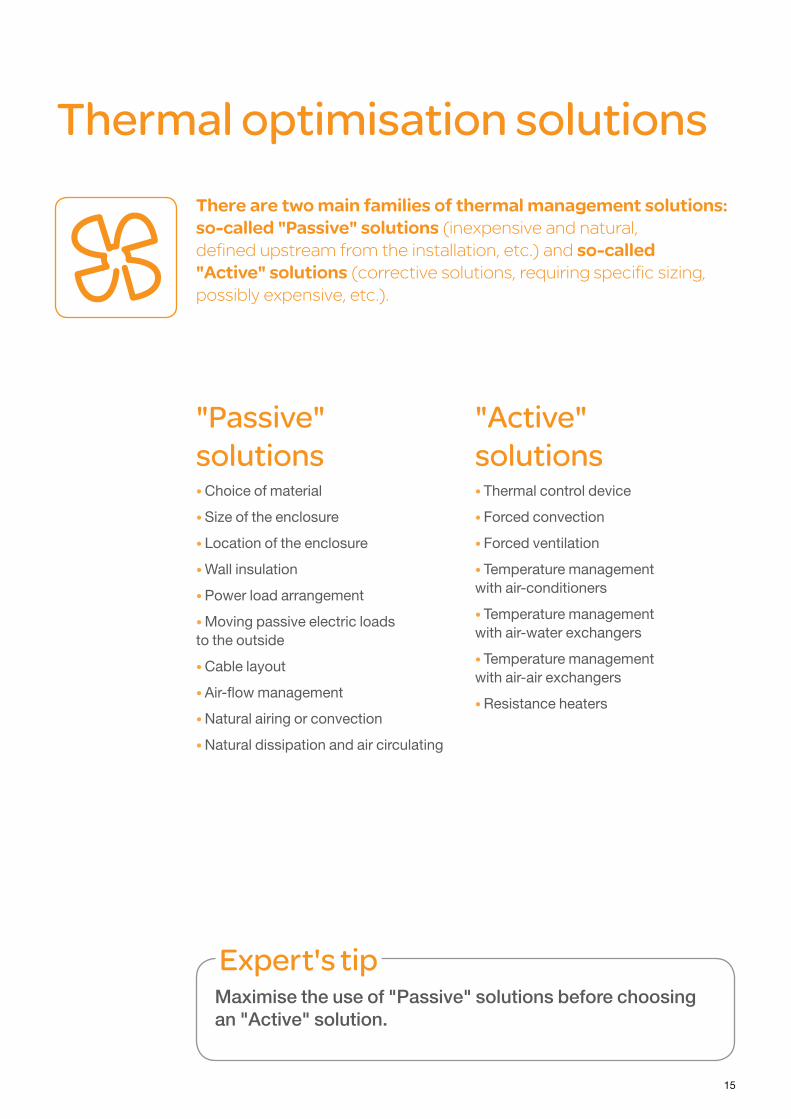
Thermal optimisation solutionsThere are two main families of thermal management solutions: so-called "Passive" solutions(inexpensiveandnatural, definedupstreamfromtheinstallation,etc.)andso-called "Active" solutions(correctivesolutions,requiringspecificsizing,possiblyexpensive,etc.).
"Passive" solutions• Choice of material
• Size of the enclosure
• Location of the enclosure
• Wall insulation
• Power load arrangement
• Moving passive electric loads to the outside
• Cable layout
• Air-flow management
• Natural airing or convection
• Natural dissipation and air circulating
"Active" solutions• Thermal control device
• Forced convection
• Forced ventilation
• Temperature management with air-conditioners
• Temperature management with air-water exchangers
• Temperature management with air-air exchangers
• Resistance heaters
Expert's tipMaximise the use of "Passive" solutions before choosing an "Active" solution.

16
Control Panel - Technical Guide • Howtoreducedamagetocomponentsthrougheffectivethermalmanagement
"Passive" solutions
Choice of material1 Thechoiceofmaterialfortheenclosure(steel,polyester)isessentialforensuring the natural dissipation of caloriesreleasedby theelectricalorelectronicdevices.
Zoom on… the phenomenon of natural dissipation of calories
Natural dissipation of calories depends on the total heat-transmission coefficient: K.
• Total heat transmission = All processes that contribute to heat transmission:
Q = K x S x (Te – Ti)
Where,
• K = Heat flow when stationary, divided by the surface area and the temperature difference between the equipment on either side of the system.
It is measured in W/m2 x °K.
The three forms of heat transfer are included: conduction, convection and transmission.
Mean values of KForiron:
5,0 to 5,5
Foraluminium:
12,0
Forpolyester:
3,5
Example of calculating natural dissipation
CASE
No.1
Enclosure specifications: Calculation:
Dimensions: 1800 x 600 x 500 mmMaterial: painted sheet steel, 1.5 mmPosition: back to the wallLoss of power (Pd): 500 WExternal temp (Te): 27°C
Ti = Te + Pd/(Se x K)S = 3.55 m²Ti = 27 + (500/5.5 x 3.55) = 27 + (500/19.525) = 27 + 25.6 = 53
Ti= 53°C
CASE
No.2
Enclosure specifications: Calculation:
Dimensions: 2000 x 800 x 600 mmMaterial: painted sheet steel, 1.5 mmPosition: back to the wallLoss of power (Pd): 500 WExternal temp (Te): 27°C
Ti = Te + Pd/(Se x K)S = 5.07 m²Ti = 27 + (500/5.5 x 5.07) = 27 + (500/27.885) = 27 + 17.9 = 45
Ti= 45°C
Expert's tipWhen the external temperature is favourable (< 35°C), increasing the size of the enclosure makes it possible to reduce the internal operating temperature and slow down a possible temperature rise.
17
Thermal optimisation solutions •"Passive"solutions
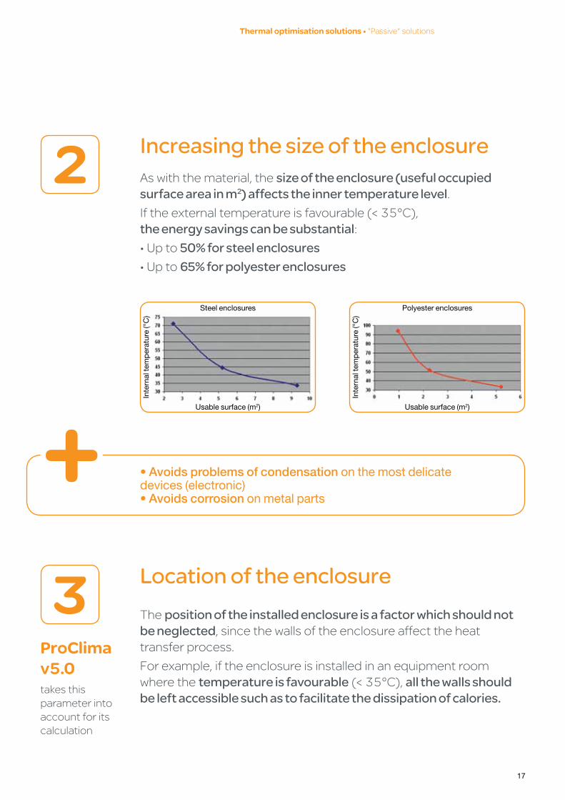
Increasing the size of the enclosure2 Aswiththematerial,thesize of the enclosure (useful occupied surface area in m2) affects the inner temperature level.Iftheexternaltemperatureisfavourable(<35°C), the energy savings can be substantial:•Upto50% for steel enclosures•Upto65% for polyester enclosures
• Avoids problems of condensation on the most delicatedevices (electronic)• Avoids corrosion on metal parts
Location of the enclosure3 Theposition of the installed enclosure is a factor which should not be neglected,sincethewallsoftheenclosureaffecttheheattransferprocess.
Forexample,iftheenclosureisinstalledinanequipmentroomwherethetemperature is favourable(<35°C),all the walls should be left accessible such as to facilitate the dissipation of calories.
ProClima v5.0 takesthisparameterintoaccountforitscalculation
Steel enclosures Polyester enclosures
Usable surface (m2) Usable surface (m2)
Inte
rnal
tem
per
atur
e (°
C)
Inte
rnal
tem
per
atur
e (°
C)

18
Control Panel - Technical Guide • Howtoreducedamagetocomponentsthrougheffectivethermalmanagement
Insulation of the enclosure4 When the external temperature is high(>35°C,forexample45°C),the calorie intake throughthesurfacesoftheenclosure increases the internal temperature.If a high external temperature (> 40°C) is permanently recorded and a source of radiation is detected, the solution will be to thermally insulate the walls of the enclosure.
Expert's tipIn the latter case, extraction must be carried out in an "Active" manner, using an air-conditioner or an air-water exchanger.
The energy saving (measured by the cooling capacity gain) is around 25% for metal enclosures and 12% for polyester enclosures.
Without insulation With insulationCooling power required: 2200 W Cooling power required: 1630 W
1Irradiated heat source (furnace for glass, ceramic, molten metal, etc.)
2Air-conditioner
3Insulation
Expert's tipInsulation can also be used as a "Passive" solution when the external temperature is very low and permanently exceeds the critical temperature of the installed devices.
E.g.: installations in cold storage rooms, outdoors (–20°C), etc.
1
22
1 3

19
Thermal optimisation solutions •"Passive"solutions
Power load arrangement5 The distribution of power loads in various groups of enclosures isveryimportant.
Beyondthe potential energy savings, loaddistributionhasmanyadvantages:
• Avoiding unwanted hot spots insidetheenclosure• Lowering the mean temperature oftheenclosure• Better adaptation of the thermal solutionConsequences of not distributing the loads = The weakest loads will receive the impact of the highest loads.
Expert's tip• A thermal partition can be used to separate loads and optimise the solution and its overall cost.
• It is preferable to separate the control enclosures and the power enclosures.
52%Increasedenergyefficiency
Example of an enclosure initially provided with several loads
Case No. 1:
More powerful thermal solution (example: air-conditioner)
Case No. 2:
Weaker and efficient thermal solution (example: ventilation)
1 Power enclosures
2 Control enclosure
3 Cooling unit
4 Ventilation
Expert's tipThe highest loads must be installed as low down as possible. In this way, the amount of air inside the enclosure can cool the dissipated heat and favour internal air convection.
Energy required for cooling 3000 W
2500 W
500 W200 W
11
2
33
4
3000 W500 W
2500 W
200 W
1
12
33
3

20
Control Panel - Technical Guide • Howtoreducedamagetocomponentsthrougheffectivethermalmanagement
Rules to be observed concerning the layout of devices inside the enclosure
• Respect the air gap distances inside the enclosure.
• Create an air column covering the entire height of the enclosure (100 to 200 mm wide), between the air intake and outlet. This will avoid overheating and losses of thermal efficiency.
1Outlet grilles
2Fan
3Drives
For easier circulation of air inside the enclosure: leave at least 100-200 mm
1
2
3
31
100 – 200 mm
2
3
3
21
Thermal optimisation solutions •"Passive"solutions
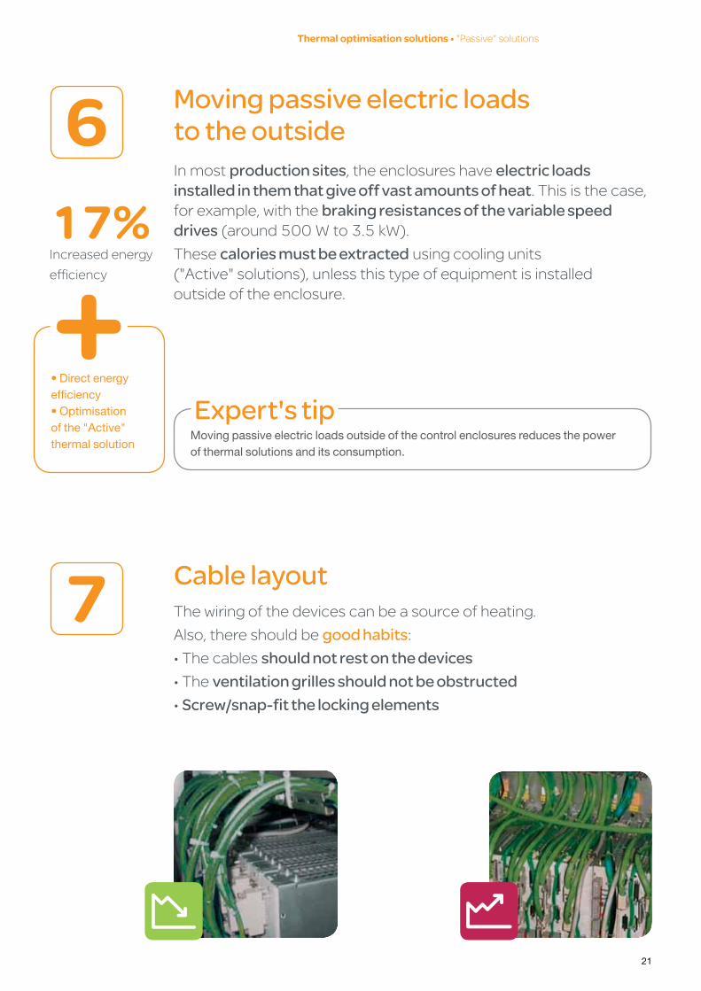
Moving passive electric loads to the outside6Inmostproduction sites,theenclosureshaveelectric loads installed in them that give off vast amounts of heat.Thisisthecase,forexample,withthebraking resistances of the variable speed drives(around500Wto3.5kW).
Thesecalories must be extractedusingcoolingunits ("Active"solutions),unlessthistypeofequipmentisinstalled outsideoftheenclosure.
Expert's tipMoving passive electric loads outside of the control enclosures reduces the power of thermal solutions and its consumption.
17%Increasedenergy
efficiency
• Direct energy efficiency• Optimisation of the "Active" thermal solution
Cable layout7 Thewiringofthedevicescanbeasourceofheating.
Also,thereshouldbegood habits:•Thecablesshould not rest on the devices•Theventilation grilles should not be obstructed•Screw/snap-fit the locking elements

22
Control Panel - Technical Guide • Howtoreducedamagetocomponentsthrougheffectivethermalmanagement
Air-flow management8 Free space above and below for ventilation
2Equipment (drives or electronic equipment)
1cable duct
Ventilation of at least 100 mm above and below
Expert's tipAvoid blocking the air outlets of the electronic equipment. Always leave a ventilation space of at least 100 mm at the top and bottom (= extended service life for the devices).
natural airing or convection9 The emission of calories inside the enclosure creates a natural convection force (hot-airevacuationflow).Inthiscase,theflowrateislowunlesstheinternalequipmentisventilated(photoontheleft).
Natural convection
100 mm
100 mm
1
2
1
1
2
1

23
natural dissipation and air circulating10Severalparametersareinvolvedinthephenomenonofnatural (or passive) dissipation of calories:
•Installation siteoftheenclosure(qualityofthesurroundingair).•Usable surfacetakenupbytheenclosure(inm2).
•Type of material(steel,polyester).•Other parameters;loadarrangement,wiring,externaltemp.,etc.
Itisessentialtomix the air inside the enclosuresinorderto:
•Equalise and lower the temperaturebydistributingthecalories.•Cool a localised hot spot.•distribute the cold airreleasedbythecoolingunits (air-conditioner,exchangers).Thisextractionsolutionshould beconsideredforaggressiveenvironmentswhenthemixing flowrateisnotsufficient.
Expert's tip• Use the ProClima v5.0 software to calculate the natural dissipation capacity of your enclosures.
• It is advisable to be able to direct the flow from the air circulating fans (e.g.: towards delicate devices, recurring hot spots, etc.).
• The greater the mixing flow, the quicker dissipation will take place.
Thermal optimisation solutions •"Passive"solutions

24
Control Panel - Technical Guide • Howtoreducedamagetocomponentsthrougheffectivethermalmanagement
natural dissipation and air circulating (continued)10Air circulating architecture for a single enclosure
Without an air circulating solution, the temperature can reach 50°C or higher at the top of the enclosure.
With an air circulating solution, the temperature is equalised throughout the enclosure. It is lower than the maximum value without convection.
Air circulating helps extract calories. It can be enough (without other "Active" solutions) if the external temperature is favourable.
50°CTi
40°CTi

25
Air circulating architecture for coupled enclosures
This consists of creating internal air circulation, with no turbulence.
Expert's tip• Leave an additional air-circulation space of at least 150-200 mm deep.
Architecture for an air-conditioner & air circulating combination
Thermal optimisation solutions •"Passive"solutions
1Air-conditioner
1

26
Control Panel - Technical Guide • Howtoreducedamagetocomponentsthrougheffectivethermalmanagement
Air circulating solutions by Schneider ElectricTheClimaSys range of air circulating fanswillallowyoutocreateyourownarchitectures:forsingleenclosures,coupledenclosuresorcombinedarchitecture.
Air circulating fans• User protection according to DIN31001.• Power: 17 W.• Dimensions: > Fan: 119 x 119 x 38 mm. > Collar: length 140 mm, fixing centre-to-centre distance : 130 mm.• Installation on ball-bearing.
27
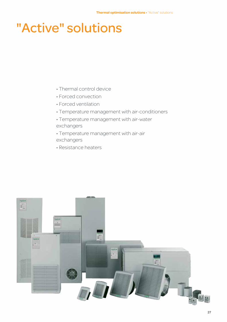
"Active" solutions
•Thermalcontroldevice
•Forcedconvection
•Forcedventilation
•Temperaturemanagementwithair-conditioners
•Temperaturemanagementwithair-waterexchangers
•Temperaturemanagementwithair-airexchangers
•Resistanceheaters
Thermal optimisation solutions •"Active"solutions
28
Control Panel - Technical Guide • Howtoreducedamagetocomponentsthrougheffectivethermalmanagement
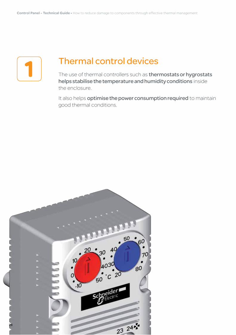
Thermal control devices1 Theuseofthermalcontrollerssuchasthermostats or hygrostats helps stabilise the temperature and humidity conditionsinside theenclosure.
Italsohelpsoptimise the power consumption requiredtomaintaingoodthermalconditions.

29
Where should the thermostat be placed in the enclosure?
Example 1:At the top (the hottest part of the enclosure)
Example 2:Next to the most delicate devices
Up to 58%Energysavings(comparedwith asolutionwithoutthermalcontrol)
Expert's tip• Two additional probes can be used to optimise the measurement.
Two fans + one thermostat equipped with two relays provide two flow levels according to the inner temperature:
• Fan 1 active if Ti = 45°C
• Fan 2 providing support if Ti = 55°C
One fan + one resistor + one thermostat equipped with two probes (S1, S2) make it possible to control two local temperature levels:
• Fan active if temperature of S1 Ti = 45ºC
• Resistor active if temperature of S1 Ti = 10°C
Probe S2 located outside (outdoor applications).
Thermal optimisation solutions •"Active"solutions
S1
S2

30
Control Panel - Technical Guide • Howtoreducedamagetocomponentsthrougheffectivethermalmanagement
Thermal control solutions by Schneider ElectricTheClimaSys range of thermal controllersismadeupofmechanical andelectronicthermostatsandelectronichygrostatsandhygrometers.
Expert's tip• Electronic thermostats and hygrostats are more accurate than mechanical models.
• A TH, HY or HYT controller can be used to reduce the consumption of the thermal solution.
• Install the thermostats in the top of the enclosure: this is the hottest part.
• As for the hygrostats, the best location is the bottom of the enclosure: this is the most humid part.
Adjustable thermostats
• NO (blue button) with normally open contact to control the starting of a fan when the temperature exceeds the displayed maximum value.
• NC (red button) with normally closed contact to control the stopping of a resistance heater when the temperature exceeds the displayed value.
• Large range of temperature control.
• Small dimensions.
Electronic thermostat with LCD screen• Three thermostats for different input voltages (9-30 V, 110-127 V, 220-240 V).
• Operating temperature: 0 °C…+ 50 °C.
• Simple programming.
• Option of installing an external sensor, for remotely reading the temperature (operating temperature: – 30 °C…+ 80 °C ).
• Ventilation and heating function (2 separate relays).
Electronic hygrotherm• Electronic hygrotherms for different input voltages (9-30 V, 110-127 V, 220-240 V).
• Operating temperature: 0 °C…+ 50 °C.
• Option of installing an external sensor, for remotely reading the temperature (operating temperature: – 30 °C…+ 80 °C).

31
Forced convection (through the appliance) with grilles2
Exemple :
The use of outlet grilles to extract the calories from the variable speed drive prevents the temperature rising inside the enclosure.
Passive convection solutions: •Sidegrilles
•Roofgrilles
•Roofelevators
Expert's tip• Select the filter type according to the environment in which the enclosure is installed (difficult, harsh, polluted, etc. or good air quality).
• Service the filter on a regular basis to avoid clogging and loss of flow.
In which circumstances is the filter not required?
Thenatural dissipation flow rate is better with no filter.However,thisisonlypossibleundercertainconditions:
•Very clean external air(e.g.:cleanrooms)
•Air-conditioned installation area
•Good filtering of the air
Thermal optimisation solutions •"Active"solutions
1Drive
Min. 100 mm
1
32
Control Panel - Technical Guide • Howtoreducedamagetocomponentsthrougheffectivethermalmanagement
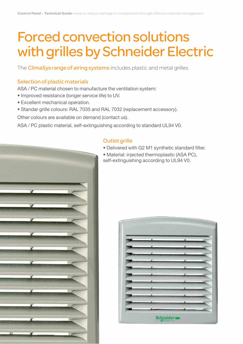
Forced convection solutions with grilles by Schneider ElectricTheClimaSys range of airing systemsincludesplasticandmetalgrilles.
Selection of plastic materialsASA / PC material chosen to manufacture the ventilation system: • Improved resistance (longer service life) to UV.• Excellent mechanical operation.• Standar grille colours: RAL 7035 and RAL 7032 (replacement accessory).
Other colours are available on demand (contact us).
ASA / PC plastic material, self-extinguishing according to standard UL94 V0.
Outlet grille• Delivered with G2 M1 synthetic standard filter. • Material: injected thermoplastic (ASA PC), self-extinguishing according to UL94 V0.

33
Forced ventilation3Whencombinedwithathermalcontroldevice,forced ventilation is one of the best solutions in terms of energy efficiency.
The performance of the forced ventilation depends greatly on external temperature conditions and air cleanliness. Also, measurements and analyses must be performed before installation.
X 2Servicelife
ofthefans
Expert's tip• The external environment must be favourable: amount of dust, temperature level and humidity level.
• The delta T (Ti – Te) should always be ≥ 5°C.
• Measure the external temperature before validating the solution.
• The thermal controller is very useful for adapting the power of the "Active" solution to the required charge level. For example, you can use two fans and only activate one or two according to the temperature.
If the enclosure is properly sized and the loads are properly distributed:
> Ventilation direction pointing inwards
> If the enclosure heats up too much (Temp. > 60°C), use a centrifugal fan (ventilation with roof extraction).
• Increased pressure thanks to the air pulse: no dust enters through the openings
Thermal optimisation solutions •"Active"solutions

34
Control Panel - Technical Guide • Howtoreducedamagetocomponentsthrougheffectivethermalmanagement
Side-mounted pulsing ventilation architecture (with thermal control)
Side-mounted ventilation solutions by Schneider Electric
TheClimaSys forced ventilation rangefulfilsmostcoolingneeds,withenergy savings and high performance levels.
To avoid the formation of air locks, check that the flow rate from the fan of the enclosure 1 is ≥ the flow rate of the drive 2 to be protected
The air intake is particularly sensitive to loss of flow
To avoid dust and air intakes: leave a distance of 100 mm from the floor
1
2
Ti
Te
150 mm

35
Where should the thermal controller be placed?
Example 1:At the top (the hottest part of the enclosure)
Example 2:Next to the most delicate devices
Two fans + one thermostat equipped with two relays provide two flow levels according to the inner temperature:
• Fan 1 active if Ti = 45°C
• Fan 2 providing support if Ti = 55°C
One fan + one resistor + one thermostat equipped with two probes (S1, S2) make it possible to control two local temperature levels:
• Fan active if temperature of S1 Ti = 45ºC
• Resistor active if temperature of S1 Ti = 10°C
Probe S2 located outside (outdoor applications).
Thermal optimisation solutions •"Active"solutions
S1
S2

36
Control Panel - Technical Guide • Howtoreducedamagetocomponentsthrougheffectivethermalmanagement
Expert's tip• If the enclosure heats up too much (Temp. ≥ 60ºC), use the top-mounted extraction ventilation, with high-speed centrifugal fan (from 500 m3/h)
• It is essential to use filter-clogging and thermal control elements.
• High cooling speed (extraction power)• Energy efficiency (with an accurate electronic controller)
Top-mounted extraction ventilation architecture (with thermal control)
The air inlet is particularly sensitive to loss of flow
To avoid dust and air intakes: leave a distance of 100 mm from the floor
Ti
Te
150 mm

37
Thermal optimisation solutions •"Active"solutions
Thecentrifugal fan (roof) has greater resistance to losses of load thantheaxialfan(side).
Actual flow (actual air entering the cabinet)
Free flow
∆P (PA)
Flow in m3/h
1 2 Fan motor curve
1
2
3
3 Plastic parts + filter
Top-mounted ventilation solutions by Schneider ElectricTheClimaSys top-mounted ventilation rangeisanaturalairingdeviceforcoupling tothetopofmetalfloor-standingenclosures.Idealsolutionforcombining withtheventilationslots.
• Natural airing device for coupling to the top of metal floor-standing enclosures.
• Solution for combining with the ventilation slots.
• Fixing to the top by means of caged nuts and special screws.
• Material: steel.
• Finish: painted with epoxy-polyester resin, textured RAL7035 grey.
• Protection rating: IP54.
Roof fan or side fan?
Centrifuge
Axial

38
Control Panel - Technical Guide • Howtoreducedamagetocomponentsthrougheffectivethermalmanagement
Air-conditionersorcoolingunitsarewidelyusedforcooling enclosures which contain devices that give off a lot of heat.Theydehumidify the total volume of the enclosurebyextractingcondensationwater.
In what cases should an air-conditioner be used?•Whentheexternal temperature is too high to ventilate(Temp.>35°C).
•Whenthe atmosphere is highly polluted,butitispossibletouse a filter to protect the external part of the air-conditioner.
Expert's tip• Use deflectors to avoid heat shocks. If the hot-air emitted by the air-conditioner is in direct contact with the air outlet of the drives, a heat shock may occur (condensation forming in the enclosure).
• Make sure the drives are correctly centred relative to the thermal solution.
• Have the filters replaced regularly by the maintenance team (e.g.: every four weeks for critical workshops).
• Avoid the typical mistake of blocking the air-conditioner air outlet. Consequences of the blockage: reduced performance and/or appearance of heat shocks.
Pay attention to the air flow direction!
Cold air must be directed downwards (not direct), observing a distance of at least 200 mm between the cold air outlet and the air intake of the drive.
Temperature management with air-conditioners 4

39
drive-cooling architecture with side-mounted air-conditioner
100 mm deflector width
> Installation at the rear of the enclosure
• Effective distribution of cold/hot-air• The solid plate is cooled and the ventilation plug of the variable speed drive is closed (convection & conduction)
Entrance hot-air
Mounting plate
Exit cooled air
Speed drive or PLC's
Cooling Unit
Thermal optimisation solutions •"Active"solutions
1Drive
2Cooling unit
80 mm
100 mm
1 2
40
Control Panel - Technical Guide • Howtoreducedamagetocomponentsthrougheffectivethermalmanagement
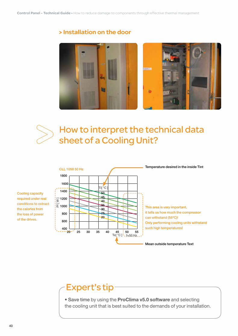
> Installation on the door
Expert's tip• Save time by using the ProClima v5.0 software and selecting the cooling unit that is best suited to the demands of your installation.
Mean outside temperature Text
This area is very important,
it tells us how much the compressor
can withstand (55ºC)!
Only performing cooling units withstand
such high temperatures!
Temperature desired in the inside Tint
Cooling capacity
required under real
conditions to extract
the calories from
the loss of power
of the drives.
How to interpret the technical data sheet of a Cooling Unit?
40 45 50 5535302520400
600
800
1000
1200
1400
1600
1800
20253035404550
CLL 1050 50 Hz
Te[ °C ]
Ti[ °C ]
Pf [
W ]
f=50 Hz

41
Expert's tip• Leave enough space to guarantee correct convection, from the roof to the bottom of the enclosure. • Leave a minimum lateral depth of 150 mm, and avoid any obstacles (risk of loss of load and performance).
drive cooling architecture with roof cooling unit
Pay attention the pipe cross-section and the number of bends in order to avoid flow losses at the drive inlet.
Drive
Thermal optimisation solutions •"Active"solutions

42
Control Panel - Technical Guide • Howtoreducedamagetocomponentsthrougheffectivethermalmanagement
1
3
2
Installation tips by Schneider Electric
• The hot-air (output) enters the second group.
• Loss of performance or shutdown if Te > 55ºC.
• The cold air of group A is aspired by the inlet of group B.
• The thermostat of B stops the compressor and stops cooling.
The two air outputs "crash", and this reduced output impairs performance.
Pay special attention to minimum clearances.
• Special care must be taken to make sure the groups are totally upright.
• A deviation of more than 3º may cause a malfunction.
The cold air outputs from inside the enclosure should be free of obstacles.
• The circuit closes and the enclosure does not cool.
• Possible condensation problems.
AB
> 300 mm
> 200 mm
> 300 mm
43
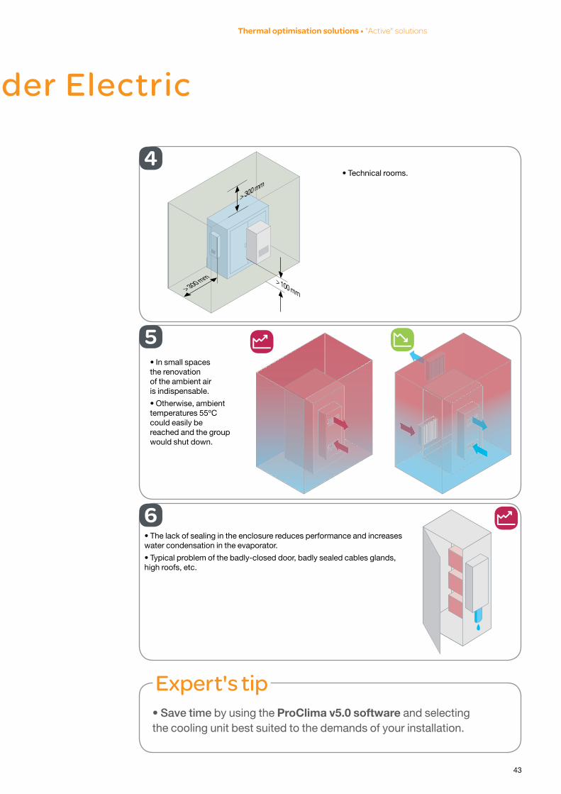
Expert's tip• Save time by using the ProClima v5.0 software and selecting the cooling unit best suited to the demands of your installation.
Installation tips by Schneider Electric
4
5• In small spaces the renovation of the ambient air is indispensable.
• Otherwise, ambient temperatures 55ºC could easily be reached and the group would shut down.
6• The lack of sealing in the enclosure reduces performance and increases water condensation in the evaporator.
• Typical problem of the badly-closed door, badly sealed cables glands, high roofs, etc.
Thermal optimisation solutions •"Active"solutions
• Technical rooms.
> 300 mm
> 300 mm > 100 mm
44
Control Panel - Technical Guide • Howtoreducedamagetocomponentsthrougheffectivethermalmanagement
Useful information!
> Side-mounted or top- mounted?
•Top-mounting should be considered when the site does not allow the installation of a side-mounted air-conditioner.>Reducedaccessibility(comparedwithaside-mountedsolution)
>Importanceofrespectinginternalaircirculationinordertoensurecorrectconvection
>Installationgenerallyusedforhigh-powerenclosures(>3kW):itmakesthedeviceheavy.
•Side-mounting is more commonly used.>Maximumaccessibility(easiermaintenance)
>Thecoldunitisnearthedevicesthatemitmostheat(variablespeeddrives).
> Cooling unit with electronic control: Advantages that should not be ignored!•Highadjustmentprecision(+/-1°C).
•Sinceitscontactsarebuiltintothedoors,theelectroniccontrollerwaits2-3minbeforeresumingoperation.Result:thecoolingfluidsreturntotheiroriginalstate.
•Indicationoftheinternaltemperaturevalue.
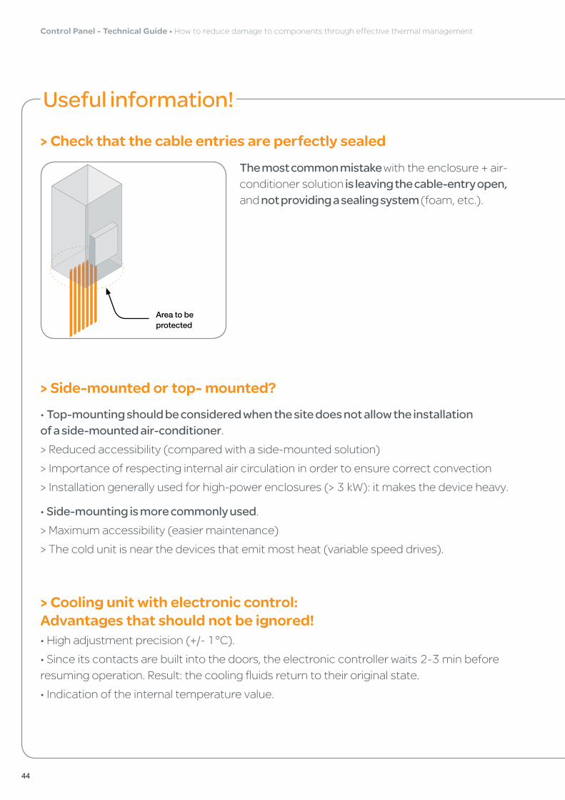
> Check that the cable entries are perfectly sealed
The most common mistake withtheenclosure+air-conditionersolution is leaving the cable-entry open, and not providing a sealing system (foam,etc.).
Area to be protected

45
> Interpretation of air-conditioner faults in the K2 contactAll the ClimaSys cooling units are equipped with a fault signalling system.
Thissignalcan indicate:•Asuddendisconnection
•Anincorrectthree-phaseconnection
•Acloggedfilter
•Excessivelyhighcompressortemp.
•Excessivelylowcompressortemp
> Filter types and filter replacement frequencyTherearedifferenttypesoffiltertosuittheinstallation environment(difficult,harsh,etc.).
Forexample:
•Polyurethane filter:forextremelydustyenvironments.
•Stainless-steel filter:foroilyenvironments
•Specialfiltersareavailableforenvironmentswithahighconcentrationoftextilefibres: donothesitatetoconsultus.
•Forextremelyaggressiveenvironments,thecondensingbattery(external)canbeprotectedbyacoating.
Thefilter replacement frequency depends on the level of pollution of the installation site.Itisessentialtobeabletoassess this level of pollutioninordertoselectthecorrectfilterqualityandanticipateitsreplacement.
Expert's tipIf the environment is pollutant-free, you can do without the filter. In this case, the cooling unit will gain performance (around 5% to 10% higher).
Thermal optimisation solutions •"Active"solutions

46
Control Panel - Technical Guide • Howtoreducedamagetocomponentsthrougheffectivethermalmanagement
Useful information! (continued)
> Evacuating condensation water (condensates)Thereareseveral ways to evacuatecondensationwater:"Passive" solutions:•Withapipe,connectedtothewateroutletoftheplant
•Withacontainer,intendedforrecoveringthewater
"Active" solutions:•Withanexternaldissipationsystem
Warning! Permanent contact between the condensation water and the walls of the enclosure can speed up the corrosion phenomenon.
• ClimaSys cooling units have an evaporation temperature between 8 and 12ºC. This is generally enough to obtain a temperature of 35ºC (in the enclosure). Furthermore, ClimaSys solutions do not generate much condensation water.• ClimaSys roof units also include a built-in evaporation system. No additional energy required for evaporating the water.
Expert's tipBefore installing an active water-evacuation solution:
• Check the amount of water generated by the air conditioning. NB.: for a dry environment, this should be low or even very low.
• Check whether it is possible to use an external water outlet.
• Check for proper water circulation: downwards (no curves on the initial level)
• Use a transparent pipe in order easily to identify any clogging or plugs in the pipe.
"Active" solutions: Condensate evaporation kit
"Passive" solutions
FB
C
G
EDA

47
Cooling unit solutions by Schneider ElectricClimaSys cooling unitsoffercomplete solutions from 240 W to 4 kW, inall installation versions:sideandroof.
• High efficiency
• Withstands extreme temperature conditions (up to 55 ºC)
• Guaranteed protection rating: IP 54 and IP 55 (range SLIM)
• Built-in adjustable thermostat
• Automatic evaporation system (roof-mounting installation)
• Maximum security
• Easy maintenance (access to the condensers)
• Environmentally friendly: R134a (HFC) eco-friendly gas
Thermal optimisation solutions •"Active"solutions

48
Control Panel - Technical Guide • Howtoreducedamagetocomponentsthrougheffectivethermalmanagement
Temperature management with air-water exchangers5Air-waterexchangersareusedmainlyforcooling or heating enclosures installed in difficult or harsh environments: cemeteries,paintproductionchains,oilyworkshops,etc. Places where filters clog very quickly.
Thissolution is completely sealed(uptoIP54). Theair-waterexchangeriscapableofextracting a large number of caloriesfromtheenclosure(byfluidexchange). Thesecaloriesarethenreleasedoutsidetheplant (chiller-typecoolingunit).
Thismeansthatthewatercancomefromothersources.
Expert's tip• Save time by using the ProClima v5.0 software, selecting the air-water exchanger that is best suited to the demands of your installation.
• Completely sealed assembly (up to IP 55). Ideal solution for highly-polluted environments and/or those with a high level of humidity (e.g.: water-treatment plants, bottling plants, wastewater plants, etc.).• Calories dissipated to the outside.• Water temperature can be checked at any time. The same goes for cooling power.
Example 1: Printing machines
Constraints: High evacuation of calories + high seal
Example 2: Paint production chain
Constraints: Level of dust (filters blocking) + humidity/condensation
49
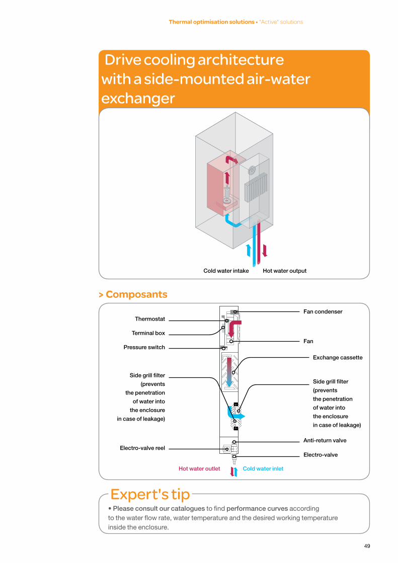
> Composants
Expert's tip• Please consult our catalogues to find performance curves according to the water flow rate, water temperature and the desired working temperature inside the enclosure.
Thermostat
Terminal box
Pressure switch
Side grill filter
(prevents
the penetration
of water into
the enclosure
in case of leakage)
Electro-valve reel
Hot water outlet Cold water inlet
Electro-valve
Anti-return valve
Side grill filter
(prevents
the penetration
of water into
the enclosure
in case of leakage)
Exchange cassette
Fan
drive cooling architecture with a side-mounted air-water exchanger
Cold water intake Hot water output
Fan condenser
Thermal optimisation solutions •"Active"solutions
50
Control Panel - Technical Guide • Howtoreducedamagetocomponentsthrougheffectivethermalmanagement
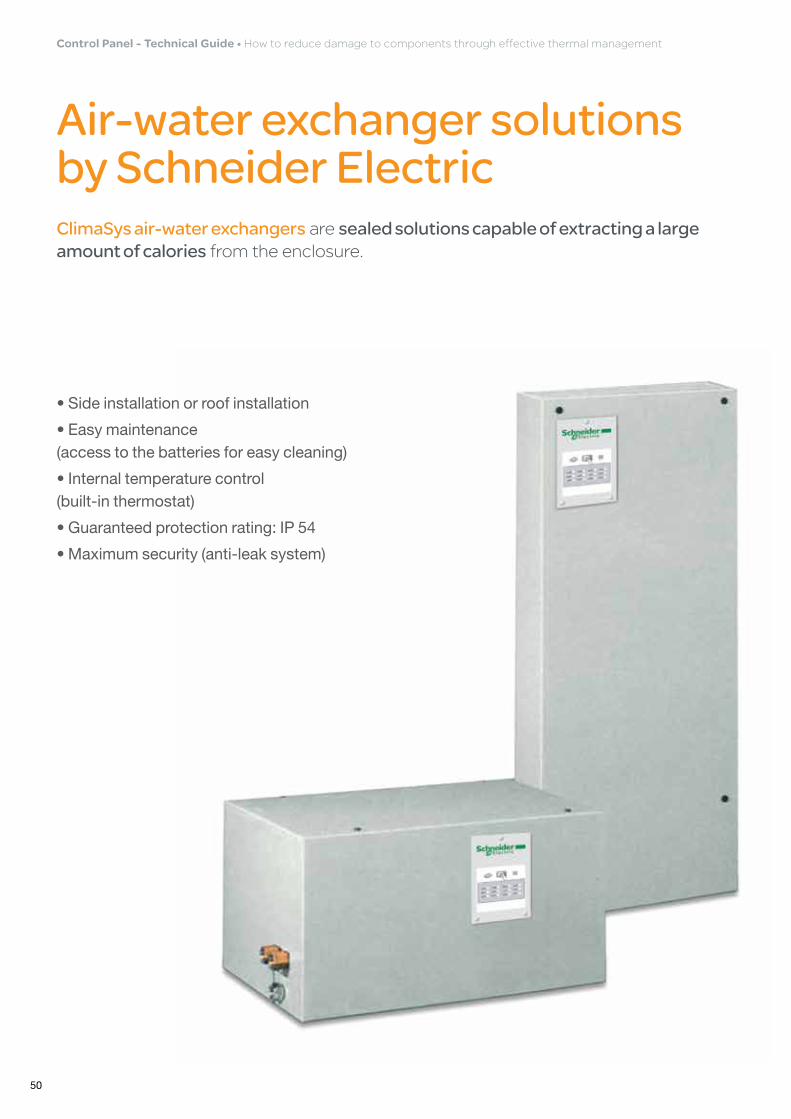
Air-water exchanger solutions by Schneider ElectricClimaSys air-water exchangersaresealed solutions capable of extracting a large amount of caloriesfromtheenclosure.
• Side installation or roof installation
• Easy maintenance (access to the batteries for easy cleaning)
• Internal temperature control (built-in thermostat)
• Guaranteed protection rating: IP 54
• Maximum security (anti-leak system)

51
Temperature management with air-air exchangers6Theuseofair-airexchangersrequiresatemperature difference between the inside of the enclosure and the outside of at least 10°C(Ti>Te).
• Inner temperature (Ti) always higher than the outer temperature (Te)
• Protection rating maintained: IP54
• Much lower maintenance frequency than fans.
• Works without a filter: the inner and outer air circuits are kept separate by the exchanger.
• Ideal solution for:> Equipment rooms (mean temp. of 25 ºC) > Already air-conditioned sites> Agri-business industries (good temperature but corrosive environment)
Expert's tip• Save time by using the ProClima v5.0 software, selecting the air-air exchanger that is best suited to the demands of your installation.
• Perform regular preventive maintenance of the battery of the exchanger.
Thermal optimisation solutions •"Active"solutions

52
Control Panel - Technical Guide • Howtoreducedamagetocomponentsthrougheffectivethermalmanagement
drive-cooling architecture with a side-mounted air-air exchanger
Parts
Ti>Te
• Exchange cassette
• Two Fans. For the inside circuit (permanent operation) and for the outside circuit (driven by the thermostat)
• They are of the centrifugal type, with good behaviour in case of pressure losses
• Thermostat installed as standard. It controls the operation of the outside fan
Ti
Te
53
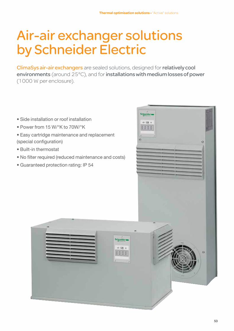
Air-air exchanger solutions by Schneider ElectricClimaSys air-air exchangersaresealedsolutions,designedforrelatively cool environments(around25°C),andforinstallations with medium losses of power (1000Wperenclosure).
• Side installation or roof installation
• Power from 15 W/°K to 70W/°K
• Easy cartridge maintenance and replacement (special configuration)
• Built-in thermostat
• No filter required (reduced maintenance and costs)
• Guaranteed protection rating: IP 54
Thermal optimisation solutions •"Active"solutions

54
Control Panel - Technical Guide • Howtoreducedamagetocomponentsthrougheffectivethermalmanagement
Resistance heaters7 External temperature changes(outdoorinstallations)orextreme temperature levels(<5°C),cancreate a phenomenon of condensation(onelectronicdeviceslocatedinsidetheenclosure)orevencause malfunctions during the starting cycle.
• Avoids high levels of humidity• Controls the condensation phenomenon• Allows the electronic devices to be started up conveniently in cold or very cold atmospheres
Bymodifying internal temperatureofsealedenclosure(IP54or+),therelative humidityismodifiedandthequantityofwatervapour insuspensionismaintained
Expert's tip• Check that the resistance heater is correctly installed using a hygrostat (checking the relative humidity: RH as a %) or a thermostat (checking the temperature in °C or °F)
• The enclosure must be sealed to prevent humid air from entering the hot areas of the enclosure.
Where should the resistance heaters be installed?
The resistance heaters should be installed at the very bottom of the enclosure. As low as possible. Also consider the internal convection that the heat they produce will generate. This is why it is important to leave a distance of at least 150 mm between the roof of the resistor and the first device.
NB.: For large enclosures, leave a free column of air. For example, leave the space between two coupled enclosures free.
Ti = 5°C
Hr = 90%
Conditions
de départ
Ti = 10°C
Hr = 63%
Ti = 20°C
Hr = 33%
Ti = 35°C
Hr = 14%

55
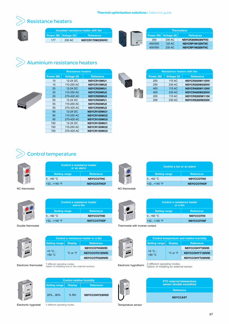
Resistance heater solutions by Schneider ElectricClimaSys resistance heatersarethebestwaytoprevent the formation of condensation or humidity inside the enclosureoreventoprotect the installation against cold or very cold environments.
Insulated or ventilated-insulated resistors• Two extraction modes: by natural convection
or with a fan
• Seven power levels from 10 W to 550 W
• Innovating design (plastic enclosure)
• Maximum security (PTC-type heater)
• Easy installation and connection
(direct clipping on 35-mm DIN rail)
• CE marking and UL and VDE conformity
Aluminium resistors• Equipped with a PTC-type detector
• Eight power levels from 10 W
to 400 W
• Improved convection
• Quick fixing
(clipping on 35-mm DIN rail)
• Connection terminal board
(heaters > 20 W)
Thermal optimisation solutions •"Active"solutions

56
Control Panel - Technical Guide • Howtoreducedamagetocomponentsthrougheffectivethermalmanagement
P r o C l i m a v 5 .0 s o f t w a r e : T h e e s s e n t i a l e x p e r t ' s t o o lYour thermal study in seven steps
1 Enter the project and customer details (optional)
2 Enter the internal and external temperature data
3 Enter the electrical specifications of the installation (voltage, power, etc.)
4 Determine the power dissipated by the equipment.
If this value is not known, ProClima v5.0 can calculated it:•Accordingtothenumberandtypeofelectric andelectronicdevicesinstalledintheenclosure
•Accordingtoatemperaturereading

57
Thermal optimisation solutions •ProClimav5.0software
P r o C l i m a v 5 .0 s o f t w a r e : T h e e s s e n t i a l e x p e r t ' s t o o l
5 Select the enclosure and the installation type
6 Select the thermal management system
7 View and print the study summary
• Reliable and accurate thermal study • Optimised solution• Saves time• User friendliness and ergonomics• Thermal values provided for all the most common devices on the market

358
Practical summary
Control Panel - Technical Guide • Howtoreducedamagetocomponentsthrougheffectivethermalmanagement

59
Good reflexes for thermal management of enclosures
•Previously visit the site and the area where the enclosure will be installed.Thiswillallowyou toassesstheexternalthermalconditions(beforemeasuring
themandanalysingthemclosely).
• Select the material that is best suited for the installation environment anditsnaturalthermal
regulationfeatures(e.g.:ventilatedarea,externalairsuitable
foruseinpassivecooling,etc.).
• Always analyse the thermal conditions inside and outside the enclosure, over a complete period and in different areas.
• Strictly observe the manufacturer's installation instructions:installationarea,mounting,wiring,dimensions
oftheairingspaces,etc.
• Give priority to "Passive" thermal management solutions before considering any "Active" solutions.
Expert's tipPlan thermal management (before installing the enclosure).
60
Control Panel - Technical Guide • Howtoreducedamagetocomponentsthrougheffectivethermalmanagement
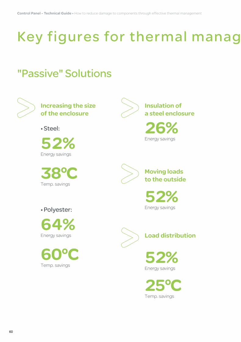
Key figures for thermal management of enclosures
"Passive" Solutions
Increasing the size of the enclosure
52%Energysavings
• Steel:
38°CTemp.savings
64%Energysavings
• Polyester:
60°CTemp.savings
26%Energysavings
Insulation of a steel enclosure
52%Energysavings
Moving loads to the outside
52%Energysavings
25°CTemp.savings
Load distribution

61
Key figures for thermal management of enclosures
"Active" Solutions
Good thermal management can extend the service life of components and avoid expensive breakdowns.
Thermal optimisation solutions •Practicalsummary
12%Energysavings
Insulation of a polyester enclosure
58%Energysavings
20°CTemp.savings
Ventilation of an enclosure

462
Choosing the best thermal management solution
Control Panel - Technical Guide • Howtoreducedamagetocomponentsthrougheffectivethermalmanagement
63
Selection guide

64
Control Panel - Technical Guide • Howtoreducedamagetocomponentsthrougheffectivethermalmanagement
System Airing Ventilating Air-air exchanger Air-water exchanger Cooling Heating
Natural convection causes the temperatureto drop inside the enclosure. Simplesolutions for this case include installinggrilles (without filter) or lifting the top.
Fans with filters are designed to evacuate a large amount of heat economically.
Air-air exchangers are equipped withan aluminium exchange cassette whichseparates the internal and external aircircuits and prevents the entry of dust.
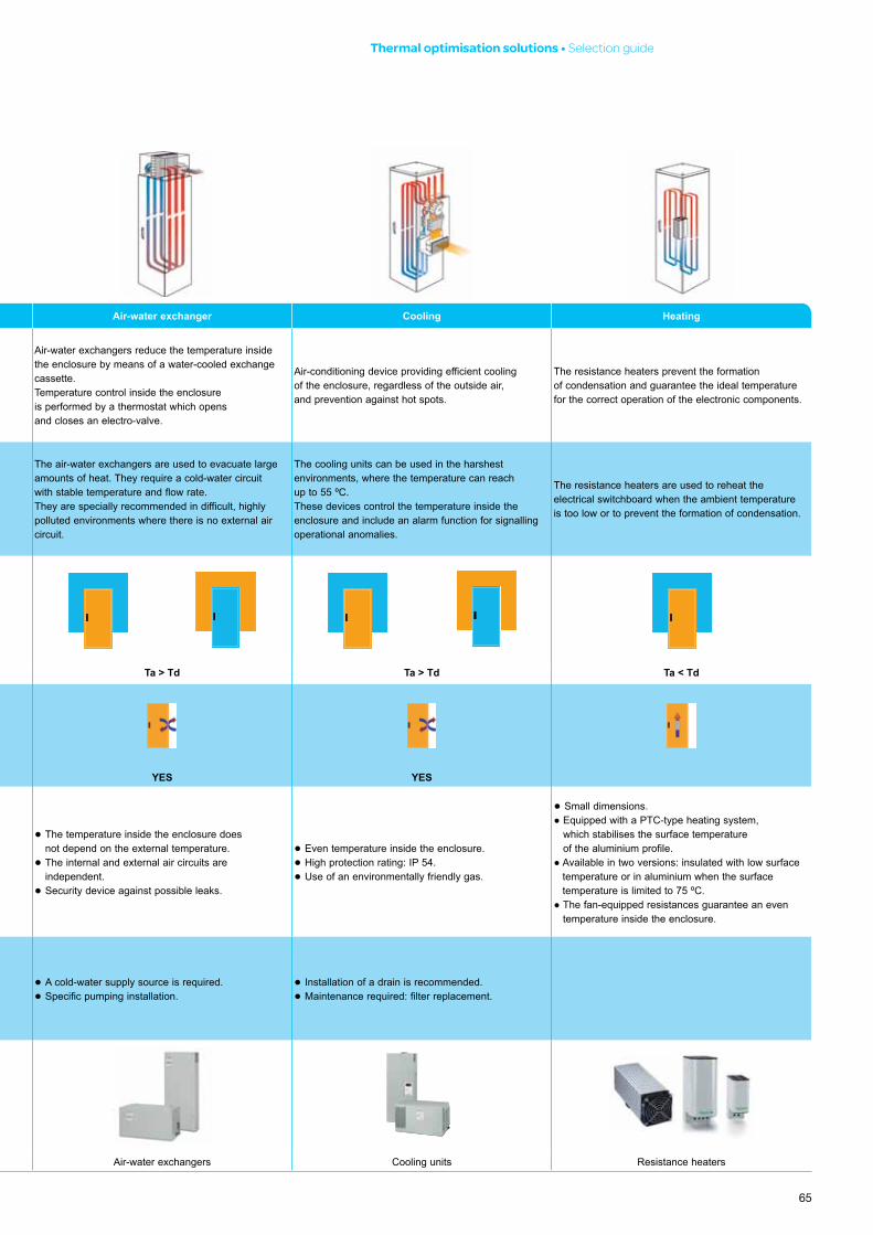
Air-water exchangers reduce the temperature insidethe enclosure by means of a water-cooled exchangecassette.Temperature control inside the enclosure is performed by a thermostat which opens and closes an electro-valve.
Air-conditioning device providing efficient coolingof the enclosure, regardless of the outside air, and prevention against hot spots.
The resistance heaters prevent the formation of condensation and guarantee the ideal temperature for the correct operation of the electronic components.
When should it be used?This solution can only be used whenthe power to be dissipated is low, in anenvironment with small amounts of dust.
When larger amounts of heat need to beevacuated in a polluted environment.
The air-air exchangers are used in highlypolluted environments or when it isnecessary to evacuate large amounts ofheat while guaranteeing the independenceof the internal and external air circuits.
The air-water exchangers are used to evacuate largeamounts of heat. They require a cold-water circuitwith stable temperature and flow rate.They are specially recommended in difficult, highlypolluted environments where there is no external aircircuit.
The cooling units can be used in the harshestenvironments, where the temperature can reachup to 55 ºC.These devices control the temperature inside theenclosure and include an alarm function for signallingoperational anomalies.
The resistance heaters are used to reheat theelectrical switchboard when the ambient temperatureis too low or to prevent the formation of condensation.
Ta: Ambient temperatureTd: Desired temperature
Ta < Td Ta < Td Ta < Td Ta > Td Ta > Td Ta < Td
The internal and externalair circuits mustbe independent.
NO NO YES YES YES
Advantages● Economic solution.● No maintenance.● Quick and easy installation.
● Economic solution.● Easy maintenance.● Quick and easy installation.● Even temperature inside the enclosure.● High protection rating: IP 54 or IP 55.
● The internal and external air circuits are independent.
● Easy maintenance.● High protection rating: IP 54.
● The temperature inside the enclosure does not depend on the external temperature.
● The internal and external air circuits are independent.
● Security device against possible leaks.
● Even temperature inside the enclosure.● High protection rating: IP 54.● Use of an environmentally friendly gas.
● Small dimensions.● Equipped with a PTC-type heating system,
which stabilises the surface temperature of the aluminium profile.
● Available in two versions: insulated with low surface temperature or in aluminium when the surface temperature is limited to 75 ºC.
● The fan-equipped resistances guarantee an even temperature inside the enclosure.
Disadvantages● Small amount of heat evacuated.● Reduction of the IP protection rating.● Entry of dust particles.
● The temperature inside the enclosure is always higher than the external tempera-ture.
● The internal and external air circuits are in contact.
● Maintenance required: filter replacement.
● The temperature inside the enclosure is always higher than the external tempera-ture.
● A cold-water supply source is required.● Specific pumping installation.
● Installation of a drain is recommended.● Maintenance required: filter replacement.
Solutions
Ventilation devices Fans and outlet grilles Air-air exchangers Air-water exchangers Cooling units Resistance heaters
65
System Airing Ventilating Air-air exchanger Air-water exchanger Cooling Heating
Natural convection causes the temperatureto drop inside the enclosure. Simplesolutions for this case include installinggrilles (without filter) or lifting the top.
Fans with filters are designed to evacuate a large amount of heat economically.
Air-air exchangers are equipped withan aluminium exchange cassette whichseparates the internal and external aircircuits and prevents the entry of dust.
Air-water exchangers reduce the temperature insidethe enclosure by means of a water-cooled exchangecassette.Temperature control inside the enclosure is performed by a thermostat which opens and closes an electro-valve.
Air-conditioning device providing efficient coolingof the enclosure, regardless of the outside air, and prevention against hot spots.
The resistance heaters prevent the formation of condensation and guarantee the ideal temperature for the correct operation of the electronic components.
When should it be used?This solution can only be used whenthe power to be dissipated is low, in anenvironment with small amounts of dust.
When larger amounts of heat need to beevacuated in a polluted environment.
The air-air exchangers are used in highlypolluted environments or when it isnecessary to evacuate large amounts ofheat while guaranteeing the independenceof the internal and external air circuits.
The air-water exchangers are used to evacuate largeamounts of heat. They require a cold-water circuitwith stable temperature and flow rate.They are specially recommended in difficult, highlypolluted environments where there is no external aircircuit.
The cooling units can be used in the harshestenvironments, where the temperature can reachup to 55 ºC.These devices control the temperature inside theenclosure and include an alarm function for signallingoperational anomalies.
The resistance heaters are used to reheat theelectrical switchboard when the ambient temperatureis too low or to prevent the formation of condensation.
Ta: Ambient temperatureTd: Desired temperature
Ta < Td Ta < Td Ta < Td Ta > Td Ta > Td Ta < Td
The internal and externalair circuits mustbe independent.
NO NO YES YES YES
Advantages● Economic solution.● No maintenance.● Quick and easy installation.
● Economic solution.● Easy maintenance.● Quick and easy installation.● Even temperature inside the enclosure.● High protection rating: IP 54 or IP 55.
● The internal and external air circuits are independent.
● Easy maintenance.● High protection rating: IP 54.
● The temperature inside the enclosure does not depend on the external temperature.
● The internal and external air circuits are independent.
● Security device against possible leaks.
● Even temperature inside the enclosure.● High protection rating: IP 54.● Use of an environmentally friendly gas.
● Small dimensions.● Equipped with a PTC-type heating system,
which stabilises the surface temperature of the aluminium profile.
● Available in two versions: insulated with low surface temperature or in aluminium when the surface temperature is limited to 75 ºC.
● The fan-equipped resistances guarantee an even temperature inside the enclosure.
Disadvantages● Small amount of heat evacuated.● Reduction of the IP protection rating.● Entry of dust particles.
● The temperature inside the enclosure is always higher than the external tempera-ture.
● The internal and external air circuits are in contact.
● Maintenance required: filter replacement.
● The temperature inside the enclosure is always higher than the external tempera-ture.
● A cold-water supply source is required.● Specific pumping installation.
● Installation of a drain is recommended.● Maintenance required: filter replacement.
Solutions
Ventilation devices Fans and outlet grilles Air-air exchangers Air-water exchangers Cooling units Resistance heaters
Thermal optimisation solutions •Selectionguide

66
Control Panel - Technical Guide • Howtoreducedamagetocomponentsthrougheffectivethermalmanagement
Fan flow rate (m3/h)
Voltage
ReferenceFree with filter
With 1 out-
let grille
With 2 out-
let grilles
50 Hz 50 Hz 50 HzFan with filter Outlet grille Colour kit
IP 55 IP 55 stainless steel EMC
RAL 7035 RAL 7032 38 25 33 230 V NSYCVF38M230PF
NSYCAG92LPF NSYCAG92LPC - - - 38 27 35 115 V NSYCVF38M115PF 58 39 47 24 V DC NSYCVF38M24DPF 44 34 41 48 V DC NSYCVF38M48DPF 85 63 71 230 V NSYCVF85M230PF
NSYCAG125LPF NSYCAG125LPC NSYCAP125LZF NSYCAP125LXF NSYCAP125LE 79 65 73 115 V NSYCVF85M115PF 80 57 77 24 V DC NSYCVF85M24DPF 79 59 68 48 V DC NSYCVF85M48DPF165 153 161 230 V NSYCVF165M230PF
NSYCAG223LPF NSYCAG223LPC NSYCAP223LZF NSYCAP223LXF NSYCAP223LE
164 153 161 115 V NSYCVF165M115PF188 171 179 24 V DC NSYCVF165M24DPF193 171 179 48 V DC NSYCVF165M48DPF302 260 268 230 V NSYCVF300M230PF302 263 271 115 V NSYCVF300M115PF262 221 229 24 V DC NSYCVF300M24DPF247 210 218 48 V DC NSYCVF300M48DPF562 473 481 230 V NSYCVF560M230PF
NSYCAG291LPF NSYCAG291LPC NSYCAP291LZF NSYCAP291LXF NSYCAP291LE582 485 494 115 V NSYCVF560M115PF838 718 728 230 V NSYCVF850M230PF983 843 854 115 V NSYCVF850M115PF931 798 809 400/440 V NSYCVF850M400PF
Ventilation systems with filters
Dimensions (mm)Reference
Height Width Depth
700 270 144 NSYCEA15W230VL 780 325 144 NSYCEA35W230VL 780 325 144 NSYCEA35W230VLE1480 450 144 NSYCEA70W230VL 340 600 360 NSYCEA50W230VRE
Air-air exchangerDimensions (mm)
ReferenceHeight Width Depth
830 360 113 NSYCEW2100W230VL950 400 190 NSYCEW3150W230VL310 600 365 NSYCEW2100W230VR
Air-water exchanger
Top-mounting modelsExternal
dimensions (mm)
Control Reference
340 X 600 X 350 Thermostat NSYCU760W230VR
400 X 700 X 400 Thermostat NSYCU1050W230VR
415 X 750 X 412 Electronic controller NSYCUE1400W230R
400 X 700 X 400 Thermostat NSYCU1460W230VR
430 X 700 X 400 Thermostat NSYCU1650W230VR
415 X 750 X 412 Electronic controller NSYCUE1800W400R
430 X 700 X 400 Thermostat NSYCU2000W400VR
470 X 800 X 450 Thermostat NSYCU2450W400VR
470 X 800 X 450 Thermostat NSYCU3100W400VR
Side-mounting modelsExternal
dimensions (mm)
Control Reference
450 X 350 X 140 Thermostat NSYCU240W230VL620 X 300 X 170 Thermostat NSYCU370W230VL800 X 350 X 195 Thermostat NSYCU760W230VL900 X 400 X 195 Thermostat NSYCU1050W230VL1010 X 400 X 240 Electronic controller NSYCUE1100W230L1010 X 400 X 240 Electronic controller NSYCUE1400W230L1010 X 400 X 240 Electronic controller NSYCUE1400W400L1000 X 400 X 220 Thermostat NSYCU1650W230VL1000 X 400 X 220 Thermostat NSYCU1800W400VL1010 X 400 X 240 Electronic controller NSYCUE1800W400L1406 X 502 X 300 Thermostat NSYCU2500W400VL1406 X 502 X 300 Thermostat NSYCU4000W400VL
Cooling unit
Covers
RAL 7035 Stainless-steelSurface-mounting Partial flush-mounting Flush-mounting Surface-mounting Partial flush-mounting Flush-mounting
NSYCUCL NSYCUCH NSYCUCF NSYCUCLX NSYCUCHX NSYCUCFX
SLIM electronic control models (modular)
1,100 W 1,500 W 2,200 W 2,700 WNSYCUB1100W230S NSYCUB1500W230S NSYCUB2200W230S NSYCUB2700W230SNSYCUB1100W400S NSYCUB1500W400S NSYCUB2200W400S NSYCUB2700W400SNSYCUB1100W115S NSYCUB1500W115S NSYCUB2200W115S
67
Thermal optimisation solutions •Selectionguide
Control a resistance heater and a fan
Setting range Reference
0...+60 °C NSYCCOTHD
+32...+140 °F NSYCCOTHDF
Double thermostat
Control a resistance heater or a fan
Setting range Reference
0...+60 °C NSYCCOTHI
+32...+140 °F NSYCCOTHIF
Thermostat with inverse contact
Control a resistance heater or a fan
Setting range Display Reference
+5 °C… +50 °C
°C or °F
NSYCCOTH30VID
NSYCCOTH120VID
NSYCCOTH230VID
Electronic thermostat 7 different operating modes.Option of installing one or two external sensors.
Control temperature and relative humidity
Setting range Display Reference
+5 °C… +50 °C
°C or °F
NSYCCOHYT30VID
NSYCCOHYT120VID
NSYCCOHYT230VID
Electronic hygrotherm 3 different operating modes.Option of installing an external sensor.
Control relative humidity
Setting range Display Reference
20%…80% % RH NSYCCOHY230VID
Electronic hygrostat 2 different operating modes.
PTC external temperature sensor (double insulation)
Reference
NSYCCAST
Temperature sensor
Thermofans
Power (W) Voltage (V) Reference
350 230 AC NSYCR350W230VTVC400/550 120 AC NSYCRP1W120VTVC400/550 230 AC NSYCRP1W230VTVC
Insulated resistance heater with fan
Power (W) Voltage (V) Reference
177 230 AC NSYCR170W230VVC
Resistance heaters
Resistance heaters with fan
Power (W) Voltage (V) Reference
250 115 AC NSYCR250W115VV250 230 AC NSYCR250W230VV400 115 AC NSYCR400W115VV400 230 AC NSYCR400W230VV200 115 AC NSYCRS200W115V200 230 AC NSYCRS200W230V
Resistance heaters
Power (W) Voltage (V) Reference
10 12-24 DC NSYCR10WU1 10 110-250 AC NSYCR10WU2 20 12-24 DC NSYCR20WU1 20 110-250 AC NSYCR20WU2 20 270-420 AC NSYCR20WU3 55 12-24 DC NSYCR55WU1 55 110-250 AC NSYCR55WU2 55 270-420 AC NSYCR55WU3 90 12-24 DC NSYCR100WU1 90 110-250 AC NSYCR100WU2 90 270-420 AC NSYCR100WU3150 12-24 DC NSYCR150WU1150 110-250 AC NSYCR150WU2150 270-420 AC NSYCR150WU3
Aluminium resistance heaters
Control a resistance heater or an alarm
Setting range Reference
0...+60 °C NSYCCOTHC
+32...+140 °F NSYCCOTHCF
NC thermostat
Control a fan or an alarm
Setting range Reference
0...+60 °C NSYCCOTHO
+32...+140 °F NSYCCOTHOF
NO thermostat
Control temperature
68
Control Panel - Technical Guide • Howtoreducedamagetocomponentsthrougheffectivethermalmanagement
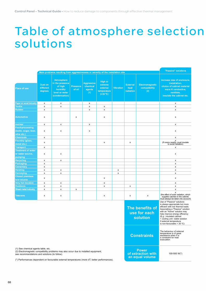
Table of atmosphere selection and associated thermal solutions
"Passive" solutions "Semi-passive" solutions "Active" ControlMain problems resulting from aggressiveness or severity of the installation site
Dust on different degrees
Atmosphere in the presence
of high humidity
level or water (condensation)
Presence of oil
Aggressive chemical agents
(1)
High or extreme external
temperature (>35 ºC)
VibrationExternal
heat radiation
Electromagnetic compatibility
(2)
Increase size of enclosure, installation,
choice of cabinet material more K conductive,
ventilate, insulate the cabinet etc.
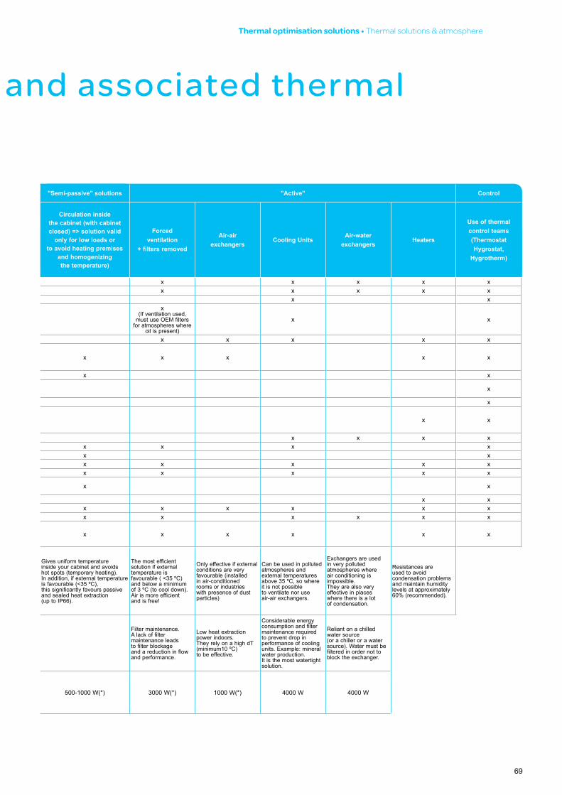
Circulation inside the cabinet (with cabinet closed) => solution valid
only for low loads or to avoid heating premises
and homogenizing the temperature)
Forced ventilation
+ filters removed
Air-air exchangers
Cooling UnitsAir-water
exchangersHeaters
Use of thermal control teams (Thermostat Hygrostat,
Hygrotherm)
Place of use
Paper or wood industry x x x x x x x x xTextile x x x x x x x x x xRubber x x x x x x
Automotive x x x x
x (If ventilation used,
must use OEM filters for atmospheres where
oil is present)
x x
nuclear x x x x x x x x xFood-processing (lactic, sugar, beer, wine etc.)
x x x x x x x x x
Chemicals x x x xFoundry (glass, metal etc.)
x x xx
(If ovens nearby, must insulate to avoid radiation)
x
Transport x x xTreatment of water or water source, pumping
x x x x x
Recycling x x x x x x xPackaging x x x x x xCementary x x x xHoisting x x x x x x x x xConveying x x x x x x x x xClosed premises low-volume
x x x x x
Very hot location x x x x x xOutdoors x x x x x x x x x x xSheet metal industry x x x x x x x x x x
Telecoms x x x x xx
(the effect of solar radiation, which supplies calories to the cabinet,
must always be taken into account)x x x x x x
(1) See chemical agents table, etc. (2) Electromagnetic compatibility problems may also occur due to installed equipment, see recommendations and solutions (to follow).
(*) Performances dependent on favourable external temperatures (more dT, better performances).
The benefits of use for each
solution
Use of "Passive" solutions is always appropriate but more efficient with low thermal loads. Associating a "Passive" solution with an "Active" solution may help improve energy efficiency (E.g.: insulated cabinet + cooling unit: viable solution if external temperature is non-favourable > 35 ºC)
Gives uniform temperature inside your cabinet and avoids hot spots (temporary heating). In addition, if external temperature is favourable (<35 ºC), this significantly favours passive and sealed heat extraction (up to IP66).
The most efficient solution if external temperature is favourable ( <35 ºC) and below a minimum of 3 ºC (to cool down). Air is more efficient and is free!
Only effective if external conditions are very favourable (installed in air-conditioned rooms or industries with presence of dust particles)
Can be used in polluted atmospheres and external temperatures above 35 ºC, so where it is not possible to ventilate nor use air-air exchangers.
Exchangers are used in very polluted atmospheres where air conditioning is impossible. They are also very effective in places where there is a lot of condensation.
Resistances are used to avoid condensation problems and maintain humidity levels at approximately 60% (recommended).
ConstraintsThe behaviour of external temperature is of great assistance when it is a constraint for heat evacuation
Filter maintenance. A lack of filter maintenance leads to filter blockage and a reduction in flow and performance.
Low heat extraction power indoors. They rely on a high dT (minimum10 ºC) to be effective.
Considerable energy consumption and filter maintenance required to prevent drop in performance of cooling units. Example: mineral water production. It is the most watertight solution.
Reliant on a chilled water source (or a chiller or a water source). Water must be filtered in order not to block the exchanger.
Power of extraction with an equal volume
100-500 W(*) 500-1000 W(*) 3000 W(*) 1000 W(*) 4000 W 4000 W
69
Thermal optimisation solutions •Thermalsolutions&atmosphere
Table of atmosphere selection and associated thermal solutions
"Passive" solutions "Semi-passive" solutions "Active" ControlMain problems resulting from aggressiveness or severity of the installation site
Dust on different degrees
Atmosphere in the presence
of high humidity
level or water (condensation)
Presence of oil
Aggressive chemical agents
(1)
High or extreme external
temperature (>35 ºC)
VibrationExternal
heat radiation
Electromagnetic compatibility
(2)
Increase size of enclosure, installation,
choice of cabinet material more K conductive,
ventilate, insulate the cabinet etc.
Circulation inside the cabinet (with cabinet closed) => solution valid
only for low loads or to avoid heating premises
and homogenizing the temperature)
Forced ventilation
+ filters removed
Air-air exchangers
Cooling UnitsAir-water
exchangersHeaters
Use of thermal control teams (Thermostat Hygrostat,
Hygrotherm)
Place of use
Paper or wood industry x x x x x x x x xTextile x x x x x x x x x xRubber x x x x x x
Automotive x x x x
x (If ventilation used,
must use OEM filters for atmospheres where
oil is present)
x x
nuclear x x x x x x x x xFood-processing (lactic, sugar, beer, wine etc.)
x x x x x x x x x
Chemicals x x x xFoundry (glass, metal etc.)
x x xx
(If ovens nearby, must insulate to avoid radiation)
x
Transport x x xTreatment of water or water source, pumping
x x x x x
Recycling x x x x x x xPackaging x x x x x xCementary x x x xHoisting x x x x x x x x xConveying x x x x x x x x xClosed premises low-volume
x x x x x
Very hot location x x x x x xOutdoors x x x x x x x x x x xSheet metal industry x x x x x x x x x x
Telecoms x x x x xx
(the effect of solar radiation, which supplies calories to the cabinet,
must always be taken into account)x x x x x x
(1) See chemical agents table, etc. (2) Electromagnetic compatibility problems may also occur due to installed equipment, see recommendations and solutions (to follow).
(*) Performances dependent on favourable external temperatures (more dT, better performances).
The benefits of use for each
solution
Use of "Passive" solutions is always appropriate but more efficient with low thermal loads. Associating a "Passive" solution with an "Active" solution may help improve energy efficiency (E.g.: insulated cabinet + cooling unit: viable solution if external temperature is non-favourable > 35 ºC)
Gives uniform temperature inside your cabinet and avoids hot spots (temporary heating). In addition, if external temperature is favourable (<35 ºC), this significantly favours passive and sealed heat extraction (up to IP66).
The most efficient solution if external temperature is favourable ( <35 ºC) and below a minimum of 3 ºC (to cool down). Air is more efficient and is free!
Only effective if external conditions are very favourable (installed in air-conditioned rooms or industries with presence of dust particles)
Can be used in polluted atmospheres and external temperatures above 35 ºC, so where it is not possible to ventilate nor use air-air exchangers.
Exchangers are used in very polluted atmospheres where air conditioning is impossible. They are also very effective in places where there is a lot of condensation.
Resistances are used to avoid condensation problems and maintain humidity levels at approximately 60% (recommended).
ConstraintsThe behaviour of external temperature is of great assistance when it is a constraint for heat evacuation
Filter maintenance. A lack of filter maintenance leads to filter blockage and a reduction in flow and performance.
Low heat extraction power indoors. They rely on a high dT (minimum10 ºC) to be effective.
Considerable energy consumption and filter maintenance required to prevent drop in performance of cooling units. Example: mineral water production. It is the most watertight solution.
Reliant on a chilled water source (or a chiller or a water source). Water must be filtered in order not to block the exchanger.
Power of extraction with an equal volume
100-500 W(*) 500-1000 W(*) 3000 W(*) 1000 W(*) 4000 W 4000 W

70
Control Panel - Technical Guide • Howtoreducedamagetocomponentsthrougheffectivethermalmanagement
notes

71
notes

10-2011CPTG001_EN
35, rue Joseph MonierCS 30323F- 92506 Rueil Malmaison Cedex
RCS Nanterre 954 503 439Capital social 896 313 776
www.schneider-electric.com
Printed on ecological paper
Schneider Electric Industries SASAs standards, specifications and designs change from time to time, please ask for confirmation of the information given in this publication.
© 2
011
- S
chne
ider
Ele
ctric
- A
ll rig
hts
rese
rved
Publication: Schneider Electric Industries SASDesign-Layout: SEDOC
Make the most of your energy™
www.schneider-electric.com