Embed Size (px)
Citation preview

How to Spell GD&T Part II: Revenge of the Circled Letters
Thomas Allsup

Return of the Jedi
• Originally to be titled "Revenge of the Jedi" but producers thought the Jedi wouldn't seek revenge.
• Some posters were made early
One such poster hangs in my home.
• I have decided that GD&T is not as noble as the Jedi.

Downloads
• This presentation is available for immediate download at our website
www.anidatech.com/SWW2010GDT2.ppt
• Additionally, you can download part one from the SWW2009 website or from our website:
www.anidatech.com/SWW2009GDT1.ppt
• And as an added bonus, you can also download the “What’s New in ASME Y14.5M-2009” seminar from the San Antonio SolidWorks Technical summit:
www.anidatech.com/SWTS2009GDT.ppt

Thomas Allsup
• Co-chair of North Texas SolidWorks User
Group
• BSME 1987 Oklahoma State University
• MSME 1990 University of Texas at Arlington
• I took my first real GD&T course in 1998 and
have been teaching it ever since
• I took my first SolidWorks class at Christmas
1999 using SolidWorks 1998 and have been
using it ever since

Previously on “How to Spell GD&T”
• When last we talked, we were near the home of a big mouse and an ocean.
The ocean was on the other side last time.
Plus last year, I had to follow a sumo on a mini-motorcycle.
This year it was only James Cameron and Avatar.
• More importantly, there are a few other new things.
The ASME Y14.5M-1994 that we have used seemingly forever was updated!
What a Long Strange Trip It’s Been
• The ASME took over the publication of the standard
from ANSI in 1989.
I still cringe when I hear people say they know
ANSI GD&T, it is kind of like saying you know
Latin as you try to speak Spanish
• 1994: slightly updated with the biggest change being
the addition of metric dimensions - the “M” in the title.
1999: reaffirmed without changes.
This is the GD&T standard that an entire
generation has used for creating and interpreting
drawings.

The More Things Change…
• Last year, the standard was changed
significantly for the first time since 1994.
Introducing the new ASME Y14.5M-2009!
New standard has new symbols & refines
some existing terms but the most obvious
change is the order & segregation of the 5
types of controls.
• None of the main 14 GD&T symbols have
changed.
This was the topic of last year’s part one.

Five Kinds of Geometric Control
• The controls act just like they sound
like: Form
Orientation
Profile
Runout
Location
• This is how we get
• F O P R L!

FOPRL Chart
Never Say Never
• When you start using the new standard, your drawing formats should be revised to have words like:
“Interpret this drawing using ASME Y14.5M-2009"
• But don't throw your old standard away:
You might need it to interpret the drawings you created or receive from others that were created from 1994 to 2009.
Don’t use the drawing date to determine what standard to use, look for the note on the drawing.
• If you create all your own drawings and never get drawings from customers then you can keep using the old standard.
• If you are like me and have to interpret whatever is thrown at me then you need to buy and start studying the new standard but keep all the old ones too.

Old and New

Where Does All This Leave Us?
• ASME Y14.5M-2009 didn’t change the 14
symbols but there were lots of other changes.
Take a look at the San Antonio SolidWorks
Technical Summit “What’s New in the
ASME Y14.5M-2009 for SolidWorks Users”
if you want a short but detailed list of the
changes.
• There are a couple new circled letters which
do impact this talk.
So maybe, we should move forward.

Circled Letters?
• What exactly are the circled letters in GD&T?
Thanks, that’s a good question.
• The circled letters are known as modifiers.
And we all know how much engineers and
designers like to modify things…
Wait for laughter.
• Seriously, GD&T modifiers change the extent
or shape of some other control.
Modifers of Extent and Size
• There is no official grouping of modifiers, but
there is a logical division:
• Extent
Changes where the tolerance is measured.
• Size
Changes the tolerance based on the size
of the feature.

List of Modifers
• Extent:
Free State
Tangent Plane
Projected Tolerance
Unequally Disposed
Profile (new)
• Size: Regardless of Feature Size
(RFS)
Regardless of Material Boundary
(RMB)
Maximum Material Condition
(MMC)
Maximum Material Boundary
(MMB)
Least Material Condition (LMC)
Least Material Boundary (LMB)
Independency (new)
F T P U S M L I
Free State
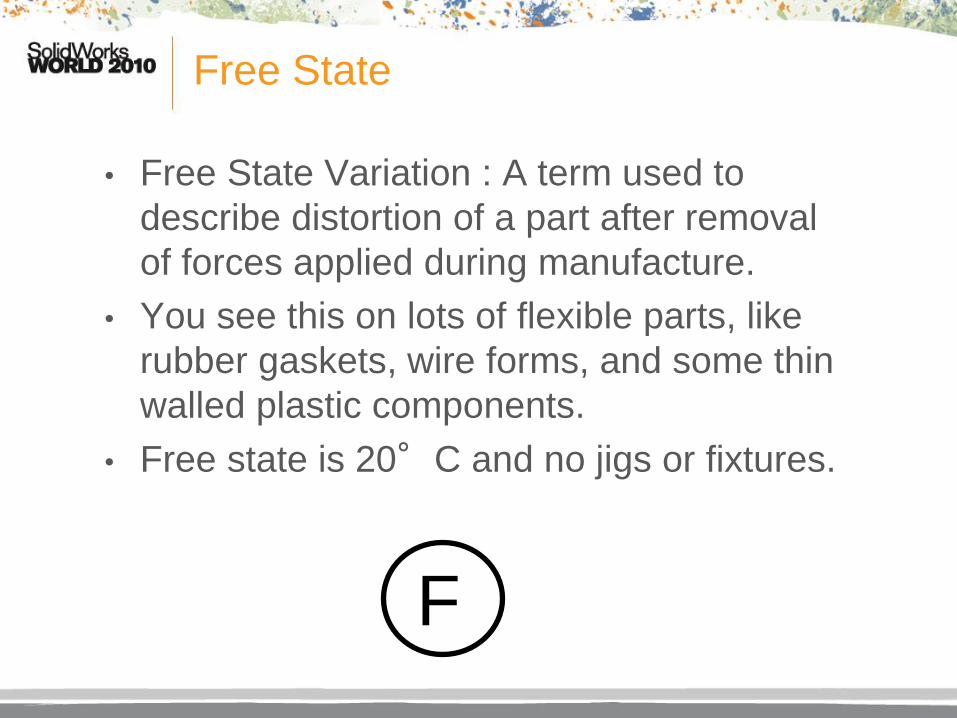
• Free State Variation : A term used to
describe distortion of a part after removal
of forces applied during manufacture.
• You see this on lots of flexible parts, like
rubber gaskets, wire forms, and some thin
walled plastic components.
• Free state is 20°C and no jigs or fixtures.
F
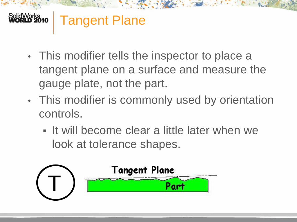
Tangent Plane
• This modifier tells the inspector to place a
tangent plane on a surface and measure the
gauge plate, not the part.
• This modifier is commonly used by orientation
controls.
It will become clear a little later when we
look at tolerance shapes.
T

Projected Tolerance Zone
• Used only with position & orientation tolerances.
• Mainly position and perpendicularity.
• Circled P appears after any modifiers and is itself followed by the projected height.
• The words are “with a projected tolerance zone of … ”
• For clarification, a chained line can be drawn and dimensioned with a minimum height dimension (not a basic dimension).
P

Projected Tolerance Zone Examples

Unequal
• New Unequally Disposed Profile Symbol is a
“U” in a circle.
• This concept has always been in the standard
but required you use chain lines and basic
dimensions to determine the distribution of a
profile tolerance zone other than 50%-50%.
• In the feature control frame you add the
symbol and the value of how much material
you allow to be added.
U
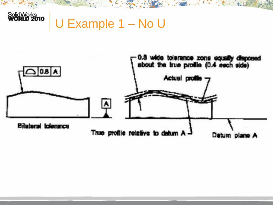
U Example 1 – No U

U Example 2 – U with Zero

U Example 3 – U maximum

U Example 4 – Arbitrary Value

U - SolidWorks
• Somehow ASME
thought U in a
circle was easier
than selecting
tools, sketch
tools, offset
entities and
changing to
construction lines.
• How did a
SolidWorks slide
get into this
GD&T talk?

Modifiers of Size
• Extent modifiers were easy.
• Now we have to move on to modifers for size.
• These are difficult for a couple reasons that
will become painfully obvious shortly.
• However difficult, these modifiers are
extremely important.
• Take a breath, and let’s go…
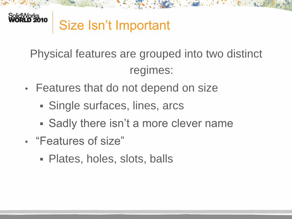
Size Isn’t Important
Physical features are grouped into two distinct
regimes:
• Features that do not depend on size
Single surfaces, lines, arcs
Sadly there isn’t a more clever name
• “Features of size”
Plates, holes, slots, balls

What’s a Feature?
• ASME Y14.5M-1994 Section 1.3.12 Defines a
Feature as the general term applied to a
physical portion of a part, such as a surface,
pin, tab, hole, or slot.
• In other words, any distinctive portion of a part
that might be dimensioned is a “feature”.
• As SolidWorks users we are very comfortable
with this definition.

What is Size?
• 1.3.24 Actual Size : The general term for the size of a
produced feature.
This is what you measure on a part.
• 1.3.27 Limits Of Size : The specified maximum and
minimum sizes.
This is the dimensions and tolerances found on
the drawing.
• 1.3.28 Nominal Size : The designation used for
purposes of general identification.
28 Gauge wire, 1” Schedule 40 pipe, 2x4 (lumber)

Feature of Size Examples
• One cylindrical surface
• One spherical surface
• Set of two opposed elements
• Set of opposed parallel surfaces
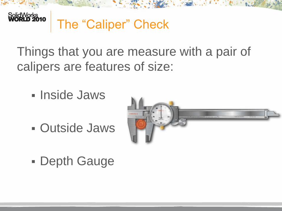
The “Caliper” Check
Things that you are measure with a pair of
calipers are features of size:
Inside Jaws
Outside Jaws
Depth Gauge

Regardless of Feature Size
• This is the default if no modifier is given.
• The tolerance zone is not affected by the actual size of the feature.
• You don’t see this symbol anymore except in GD&T training sessions.
• Just because you don’t see the symbol doesn’t mean the concept isn’t used all the time.
S

Second Rule of GD&T
• Remember the first rule of GD&T states the
limits of size are the first magnitude of control.
I had an engineering professor who said
“remember is defined as recall or boy do
you have some studying to do”.
• The second rule of GD&T states that if the
geometric tolerance is applied to a feature of
size then it is assumed to be regardless of
feature size.

Maximum Material Condition
• The stated tolerance applies when the
most material is there.
The tolerance zone increases when
there is less material – you get a “bonus
tolerance” if a hole is large.
• Examples:
Thickest plate
Smallest hole M

“Worst Case Scenario”
MMC is normally valid only when all of these
conditions exist:
• Two or more features are interrelated with position
or orientation.
• At least one of the features is a feature of size.
• The feature with which MMC is to be applied must
be a feature of size with a axis or center plane.
• Note: We used to call MMC, the “worst case”.

Least Material Condition
• The stated tolerance applies when the
least material is there.
This is a rarely used modifier.
• Examples:
Thinnest plate
Largest hole
L

Why is LMC rare?
• Most tolerance analysis is checking whether
part will go together.
• If you are checking if a male part will go into a
hole, you need to know the largest male part
and the smallest hole - both of which are MMC.
• LMC can be used to see what the maximum
clearance is in a system but that analysis is
pretty rare.
• Anyway who drove an AMC Gremlin wished
they had done a “gap” analysis.

New Names, Old Concepts
• Someone finally figured out that datums are
theoretical so there is no “material condition”.
• ASME Y14.5M-2009 section 1.3.3,1.3.4, and
1.3.49 introduce new datum terms for
Least Material Boundary (LMB)
Maximum Material Boundary (MMB)
Regardless of Material Boundary (RMB)
• The symbols are the same for the features
“conditions”.
• Features will continue to use the terms LMC,
MMC, and RFS.

Slightly Irregular
• ASME Y14.5M-2009 Section 1.3.32.2 introduces the
new term "Irregular Feature of Size"
• We’ve always had features of size
• Remember the “caliper test”?
Cylindrical surface
Spherical surface
Two opposed parallel elements or surfaces
• These are now called “regular” features of size
• Now we get to introduce “Irregular” Features of Size

Shapes of Things
• The new concept from ASME Y14.5M-2009 is
that now an arbitrary profile (possibly an
irregular feature) can be identified as a
datum.
• If that profile follows the “caliper test” then
material modifiers can be applied.
• Imagine extruded shape profiles, key holes,
splines, or other unusual shapes now being
able to be considered a datum.

Perfect Form?
Independent
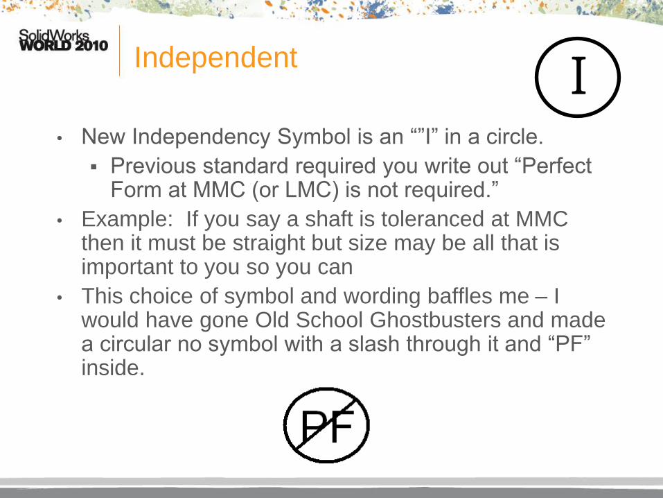
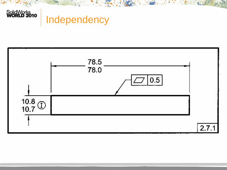
• New Independency Symbol is an “”I” in a circle.
Previous standard required you write out “Perfect Form at MMC (or LMC) is not required.”
• Example: If you say a shaft is toleranced at MMC then it must be straight but size may be all that is important to you so you can
• This choice of symbol and wording baffles me – I would have gone Old School Ghostbusters and made a circular no symbol with a slash through it and “PF” inside.
I
Independency
Form Controls
• Remember there are 4 form controls.
Straightness
Flatness
Circularity
Cylindricity
• Size doesn’t affect form so you can’t modify most of them with S,M, L, or I.
• U is only for profile.
• However, it is very acceptable to put F or T.
• P works only with straightness and because of an important exception M can be applied.

Form Straightness Exception
• Rule 1 has four (count’em four) exceptions:
Stock parts : Bars, sheets, tubing,
structural shapes
Parts subject to free state variation
Add note to a surface or feature:
PERFECT FORM AT MMC NOT
REQUIRED.
Straightness tolerance on features of
size with MMC applied.

Straightness Tolerance on Features of Size with MMC Applied
• Pretty much, just like it sounds.
• The shaft shown below can be shaped like
a “smiley face” and still be acceptable.
J

Orientation
• Remember there are three orientation
controls:
Parallelism
Angularity
Perpendicularity
• Depending upon the features you can modify
orientation controls with everything except U.

Profile
• Remember there are two profile controls:
Line Profile
Surface Profile
• You can modify profile with all the modifiers.

Runout
• Remember there are two runout controls:
Circular runout
Total runout
• You can’t modify any runout controls.
That’s simple!
Location
• Remember there are three kinds of location
controls:
Position
Symmetry
Concentricity
• Position can be modified with everything except U.
• Symmetry and Concentricity can only be modified
by F.

Example #1
All I get at MMC of both Datam B and hole is .01!
At LMC of both, I get .03!

Example #2

Example #3

SolidWorks Note
• This is a SolidWorks seminar.
Maybe I should mention something
“SolidWorksy” (that’s a real word).
• How about a tip about how to add custom
symbols?
• The symbols, as shipped with SolidWorks
2009 and 2010, do not have the new modifier
symbols for Unequal and Independency.
Let’s add them to the library.

Special Thanks
• While at the San Antonio SolidWorks
Technical Summit, I was lamenting that we
would have to wait for SolidWorks to update
the symbol library for the new standard.
• Santiago Laverde, CSWP, of Halliburton in
Houston sent me his notes on how to modify
and add geometric symbols.
• These notes come from his idea.

Editing GTOL.SYM
• Go to your SolidWorks Load
Directory\Lang\English
Or whatever your native language is.
• There will be a file GTOL.SYM.
• Make a copy of the file using another name.
This is so you can recover quickly if
something bad happens.
• Use a text editor to open the file.
• The header of the file has great hints on how
to make your own symbols.
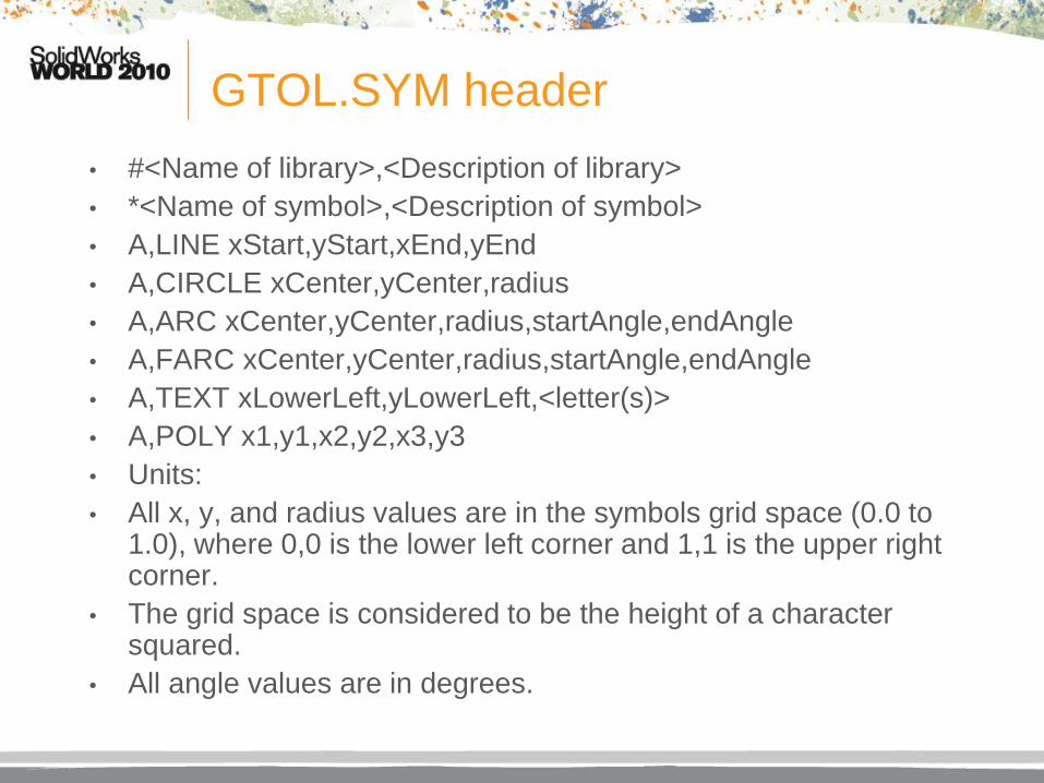
GTOL.SYM header
• #<Name of library>,<Description of library>
• *<Name of symbol>,<Description of symbol>
• A,LINE xStart,yStart,xEnd,yEnd
• A,CIRCLE xCenter,yCenter,radius
• A,ARC xCenter,yCenter,radius,startAngle,endAngle
• A,FARC xCenter,yCenter,radius,startAngle,endAngle
• A,TEXT xLowerLeft,yLowerLeft,<letter(s)>
• A,POLY x1,y1,x2,y2,x3,y3
• Units:
• All x, y, and radius values are in the symbols grid space (0.0 to 1.0), where 0,0 is the lower left corner and 1,1 is the upper right corner.
• The grid space is considered to be the height of a character squared.
• All angle values are in degrees.

Existing Modifying Symbols
• #MOD,Modifying Symbols
• *FMC,Regardless of Feature Size
• A,CIRCLE .5,.5,.75
• A,TEXT .5,.5,S
• *FREES,Free State
• A,CIRCLE .5,.5,.75
• A,TEXT .5,.5,F
• *LMC,Least Material Condition
• A,CIRCLE .5,.5,.75
• A,TEXT .5,.5,L
• *MMC,Maximum Material Condition
• A,CIRCLE .5,.5,.75
• A,TEXT .5,.5,M
• *PTZ,Projected Tolerance Zone
• A,CIRCLE .5,.5,.75
• A,TEXT .5,.5,P
• *EP,Encompassing
• A,CIRCLE .5,.5,.75
• A,TEXT .5,.5,E
• *TANP,Tangent Plane
• A,CIRCLE .5,.5,.75
• A,TEXT .5,.5,T

Add These New Symbols
• #MOD,Modifying Symbols
• *UNEQ,Unequal Distribution
• A,CIRCLE .5,.5,.75
• A,TEXT .5,.5,U
• *IND,Independency
• A,CIRCLE .5,.5,.75
• A,TEXT .5,.5,I

What the Farc?
• FARC is a filled arc.
• Try this:
*ORIGIN,Origin
A,FARC 1,0,1,0,90
A,ARC 1,0,1,90,180
A,FARC 1,0,1,180,270
A,ARC 1,0,1,270,360
• By the way, POLY is a
closed polygon.
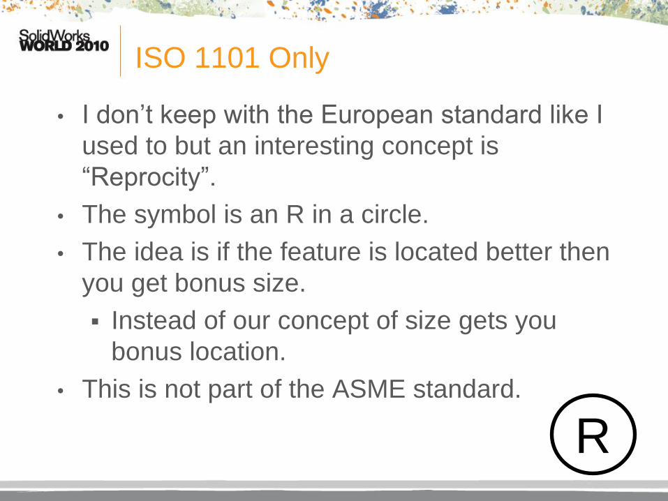
ISO 1101 Only
• I don’t keep with the European standard like I
used to but an interesting concept is
“Reprocity”.
• The symbol is an R in a circle.
• The idea is if the feature is located better then
you get bonus size.
Instead of our concept of size gets you
bonus location.
• This is not part of the ASME standard.
R

The Modifier That Isn’t Circled
• There is one more kind of modifier that
doesn’t fit anywhere and is new.
• Translation (Datum)
This allows a datum to establish orientation
but allows it to “translate”.
This is better talked about when you
discuss datums.
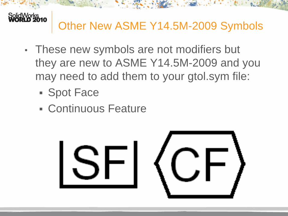
Other New ASME Y14.5M-2009 Symbols
• These new symbols are not modifiers but
they are new to ASME Y14.5M-2009 and you
may need to add them to your gtol.sym file:
Spot Face
Continuous Feature

Review of Modifers
• Extent:
Free State
Tangent Plane
Projected Tolerance
Unequally Disposed
Profile (new)
• Size: Regardless of Feature Size
(RFS)
Regardless of Material Boundary
(RMB)
Maximum Material Condition
(MMC)
Maximum Material Boundary
(MMB)
Least Material Condition (LMC)
Least Material Boundary (LMB)
Independency (new)
F T P U S M L I

See You Next Year for Part Three
• Possible Topics:
Datums – Theoretically Speaking
The Rise of the Tolerance Zone Ranger
The Wrath of Fritz and Platz
Gaging for Fun and Profit
Exceptions to the Rules
Fixed and Floating Fastener Calculations – I couldn’t think of anything clever for this one.
• Who Knows What?
Questions
• Last year, there were some really good but
really in-depth questions that I didn’t explain
completely.
• If I blow you off this morning or don’t explain
something to your satisfaction in the next few
minutes, hunt me down over the next days
and ask your question again.
• So, what do you want to ask?
• Thomas Allsup - [email protected]