Embed Size (px)
Citation preview
How to stack multiple NCT192 IP DSLAMs in untagged mode and VLAN tagged mode
Introduction
The NetComm NCT192 192-port IP DSLAM supports service capacity expansion via unit stacking. A maximum of ten NCT192s are allowed to be stacked which makes a system to have 1920 ports in total. All the NCT192 in a stacked system will share a single uplink interface to connect to the backbone network. Refer to Figure 1 for a brief illustration to this implementation structure.
The advantage of using the stacking topology implementation in comparison to a star topology implementation is that a Gigabit Ethernet switch can be eliminated. Refer to Figure 2 for an illustration of a star-topology implementation.
This white paper is written to demonstrate the concept and fundamental procedures involved in setting up multiple NCT192 system for untagged and Virtual Local Area Network (VLAN) tagged application. This system stacking concept is demonstrated through setting up two NCT192 systems in stacking topology. This white paper contains two parts. Part 1 describes the steps and configuration in setting up two NCT192s in untagged mode; Part 2 describes that in VLAN tagged mode.
It is recommended that the readers of this document have read and understood the NCT192 System Installation Guide, the Local Craft Terminal (LCT) software operation guide and the Command Line Interface (CLI) operation guide in the NCT192 user manual. It is assumed that readers of this document understand the concepts used in Virtual Local Area Network (VLAN), such as trunk mode and access mode. The configuration for the Gigabit Ethernet (GE) VLAN switch is not described in this white paper.
How to stack multiple NCT192 IP DSLAMs in untagged and VLAN tagged mode.docDoc Version: 1.0 page 1 March 2009C.L
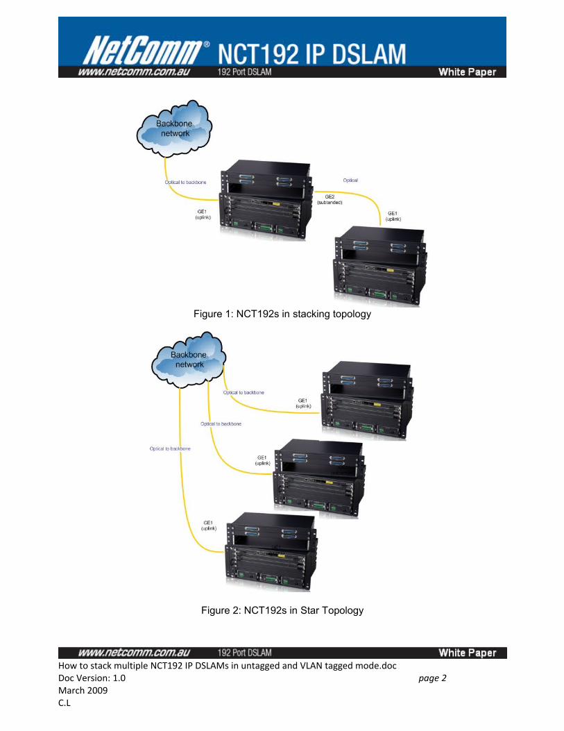
Figure 1: NCT192s in stacking topology
Figure 2: NCT192s in Star Topology
How to stack multiple NCT192 IP DSLAMs in untagged and VLAN tagged mode.docDoc Version: 1.0 page 2 March 2009C.L
Terms & Concepts
VLAN VLAN stands for Virtual Local Area Network. It is a group of hosts with a common set of requirements that communicate as if they were attached to the same broadcast domain. A VLAN allows a physical network to be divided into several logical networks. An end device can be assigned to more than one VLAN group. Devices from different VLANs can not communicate to each other. VLAN can provide isolation and security to users and increase network performance by limiting broadcast domain. VLAN tag can be added to the MAC header to identify the VLAN membership of a frame across bridges. A tagged frame is four bytes longer than an untagged frame. The GE and xDSL interfaces of the NCT192 are capable of passing tagged or untagged frames.
NCT192 Network Control (NC) card supports two global modes: ‘Untagged only’ and ‘Tagged only’. This means when the NC card is configured in ‘Untagged Mode’, the traffic that going through the uplink or downlink interface of the IP DSLAM will be untagged. This also means when the NC card is configured in ‘Tagged Mode’, the traffic going through the uplink or downlink interface of the IP DSLAM will be tagged. For further NCT192 VLAN terms and concepts please refer the NCT192 User Manual.
Stacked VLAN Database Management
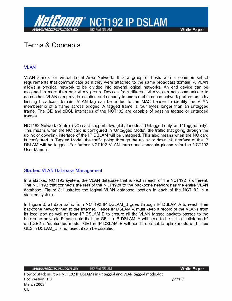
In a stacked NCT192 system, the VLAN database that is kept in each of the NCT192 is different. The NCT192 that connects the rest of the NCT192s to the backbone network has the entire VLAN database. Figure 3 illustrates the logical VLAN database location in each of the NCT192 in a stacked system.
In Figure 3, all data traffic from NCT192 IP DSLAM_B goes through IP DSLAM A to reach their backbone network then to the Internet. Hence IP DSLAM A must keep a record of the VLANs from its local port as well as from IP DSLAM B to ensure all the VLAN tagged packets passes to the backbone network. Please note that the GE1 in IP DSLAM_A will need to be set to ‘uplink mode’ and GE2 in ‘subtended mode’; GE1 in IP DSLAM_B will need to be set to uplink mode and since GE2 in DSLAM_B is not used, it can be disabled.
How to stack multiple NCT192 IP DSLAMs in untagged and VLAN tagged mode.docDoc Version: 1.0 page 3 March 2009C.L
Figure 3: Stacked VLAN Database in NCT192
System Management
The NCT192 supports SNMP, CLI, Telnet, FTP and TFTP for system management. A proprietary SNMP management program is used to manage NCT192 locally or remotely. This software is called the Local Craft Terminal (LCT) and it comes with the product CD ROM when the product is shipped. The NCT192 does not support single IP management in its current firmware. This means the management interface IP address for NCT192s will need to be different and you will need to connect to each system at a time to perform configuration.
The default inbound management IP address for the NCT192 local management port is 192.168.192.1/24; the default outbound management IP address for NCT192 uplink port is via VLAN 2094 with IP address 172.17.192.1/16; the default user name and SNMP community for logging into the LCT is admin/netman.
It is recommended to use the local management port for device management. Figure 5 illustrates how multiple NCT192s are managed.
How to stack multiple NCT192 IP DSLAMs in untagged and VLAN tagged mode.docDoc Version: 1.0 page 4 March 2009C.L
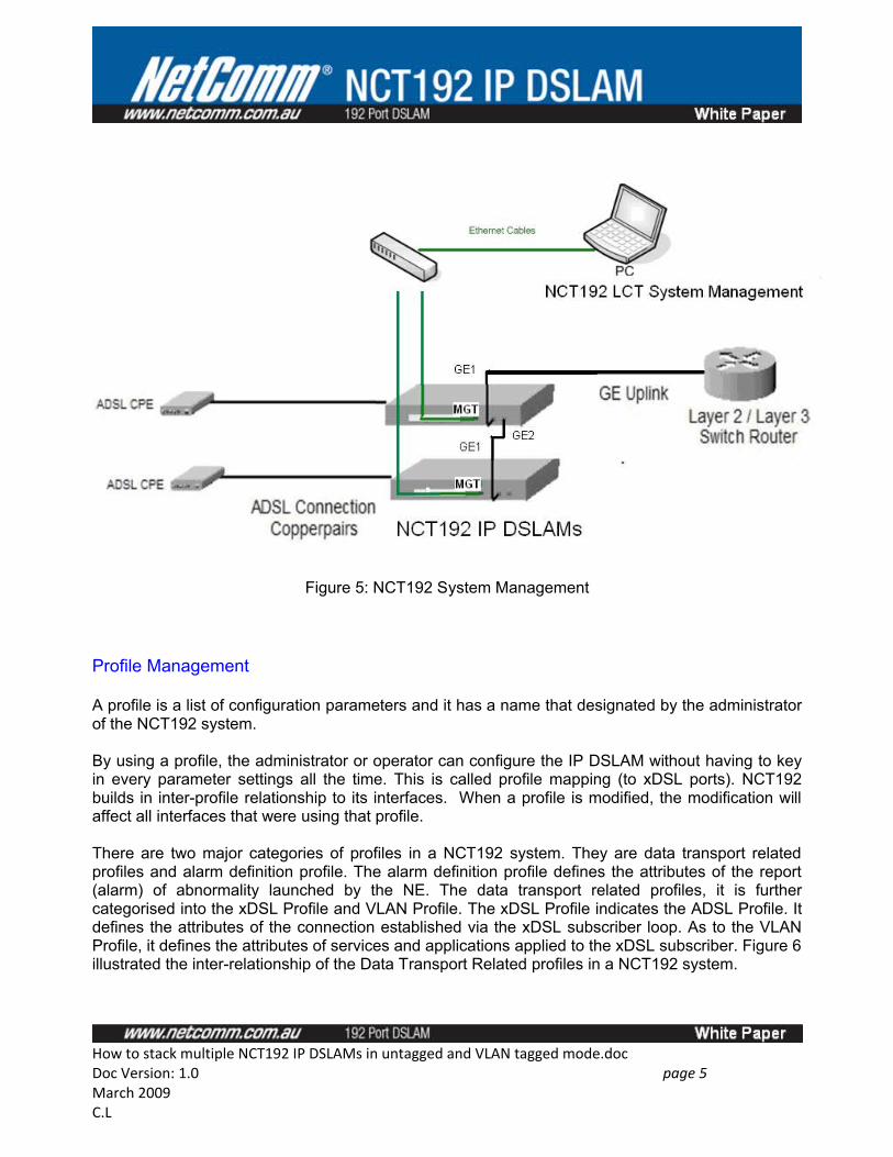
Figure 5: NCT192 System Management
Profile Management
A profile is a list of configuration parameters and it has a name that designated by the administrator of the NCT192 system.
By using a profile, the administrator or operator can configure the IP DSLAM without having to key in every parameter settings all the time. This is called profile mapping (to xDSL ports). NCT192 builds in inter-profile relationship to its interfaces. When a profile is modified, the modification will affect all interfaces that were using that profile.
There are two major categories of profiles in a NCT192 system. They are data transport related profiles and alarm definition profile. The alarm definition profile defines the attributes of the report (alarm) of abnormality launched by the NE. The data transport related profiles, it is further categorised into the xDSL Profile and VLAN Profile. The xDSL Profile indicates the ADSL Profile. It defines the attributes of the connection established via the xDSL subscriber loop. As to the VLAN Profile, it defines the attributes of services and applications applied to the xDSL subscriber. Figure 6 illustrated the inter-relationship of the Data Transport Related profiles in a NCT192 system.
How to stack multiple NCT192 IP DSLAMs in untagged and VLAN tagged mode.docDoc Version: 1.0 page 5 March 2009C.L
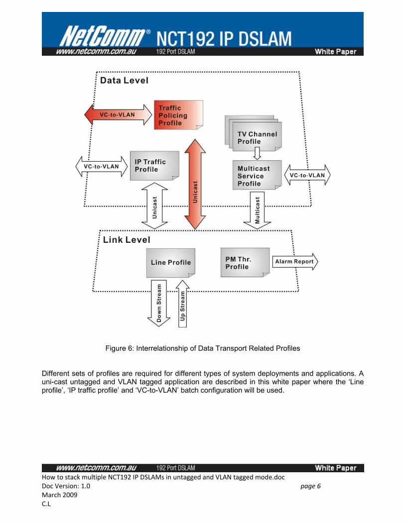
Figure 6: Interrelationship of Data Transport Related Profiles
Different sets of profiles are required for different types of system deployments and applications. A uni-cast untagged and VLAN tagged application are described in this white paper where the ‘Line profile’, ‘IP traffic profile’ and ‘VC-to-VLAN’ batch configuration will be used.
How to stack multiple NCT192 IP DSLAMs in untagged and VLAN tagged mode.docDoc Version: 1.0 page 6 March 2009C.L
GE
It stands for Gigabit Ethernet. It is the standard for a high-speed Ethernet. It has a maximum data transmission rate of 1000Mb/s or 1 Gigabit/s.
LCT
It stands for Local Craft Terminal. It is a name for the proprietary NCT192 management program. NCT192 LCT is a SNMP management program that can monitor and control one NCT192 IP DSLAM at a time.
NE
NE/NEs mentioned in this document means NCT192 IP DSLAM unless specifically indicated.
xDSL
It is refer ADSL in this document. It covers ADSL, ADSL2, and ADSL2+, unless specifically indicated.
NC
It stands for Network Card. One network card is required to be installed in each NCT192 IP DSLAM. The product code for NCT192’s NC card is NCT1902. This product code is displayed in LCT operation menu once the NC card completes initialization.
LC
It stands for Line Card. Each NCT192 LC card has 48 ADSL ports. There are a maximum of 4 ADSL LC cards can be installed in each NCT192 system which make a system to have a total of 192 ports in total. The product code for NCT192’s LC card is NCT1901. This product code is displayed in LCT operation menu once the LC card completes initialization.
How to stack multiple NCT192 IP DSLAMs in untagged and VLAN tagged mode.docDoc Version: 1.0 page 7 March 2009C.L
System Requirement
This white paper is written using LCT to configure the stacked NCT192 system. It is recommended to use the following hardware and software to run the LCT software.
Hardware:
> Pentium 4 1.6 GHz or higher> 512 MB RAM or higher> 40 GB Hard disk> 10/100 Base-T Ethernet network card
Software:
> Operating System – Microsoft Windows 98SE/ME/2000/XP > NCT192 Installation Package (Refer to NCT192 product CD ROM)
How to stack multiple NCT192 IP DSLAMs in untagged and VLAN tagged mode.docDoc Version: 1.0 page 8 March 2009C.L
Equipment List
Hardware
2 x NCT192 systems (with 1 x NCT1902 NC Card; 1 x NCT1901 LC card in each system)2 x NCT192S POTS Splitter shelf (with 1 x NCT1901S POTS Splitter Card in each system)4 x NCT2030 Power supply for NCT192 system3 x NCT1911 Mini GBIC Fibre to Copper RJ45 GE Converters6 x CAT5E RJ45 Ethernet Cables 1 x GE VLAN Switch2 x NB6+4W_R2T8 Bridged Modem routers2 x Splitter Filter 2 x NCT1906 DSLAM cables (6m Male 180 degrees connector to Open)2 x NCT1904 DSLAM Cables (1m Male 90 degrees to 180 Male)1 x DHCP Server or IP Network (acts as the backbone for the NCT192 system)
Please note that the quantity of hardware items used in this whitepaper does not represent two fully equipped NCT192 systems. To demonstrate the concept of stacking, only one Network Card and one ADSL line card in each NCT192 system are necessary, hence the quantity for the above items are chosen.
The NCT192 has optical uplink interfaces only by default, to illustrate the system stacking concept, in this white paper, fibre to copper RJ45 GE converters are used to convert the NCT192 optical uplink connection to copper to connect to the copper backbone network.
For NCT192 power redundancy purpose, it is recommended to use two NCT2030 power supply per NCT192 system.
Software
NCT1902 Network Control Card Firmware: R2.4.1NCT1901 ADSL2+ Line Card Firmware: R2.4.0NCT192 LCT Software version: V4.6.0.5NB6+4W_R2T8 FW 3.63u Bridged firmware
How to stack multiple NCT192 IP DSLAMs in untagged and VLAN tagged mode.docDoc Version: 1.0 page 9 March 2009C.L
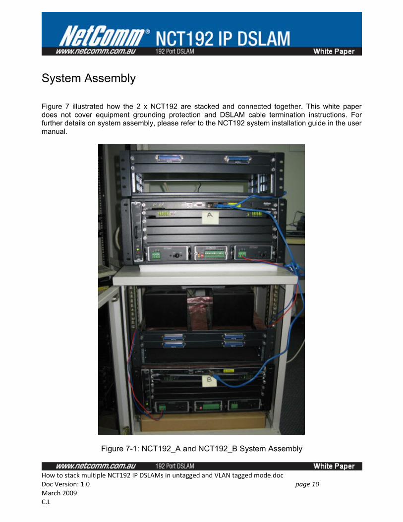
System Assembly
Figure 7 illustrated how the 2 x NCT192 are stacked and connected together. This white paper does not cover equipment grounding protection and DSLAM cable termination instructions. For further details on system assembly, please refer to the NCT192 system installation guide in the user manual.
Figure 7-1: NCT192_A and NCT192_B System Assembly
How to stack multiple NCT192 IP DSLAMs in untagged and VLAN tagged mode.docDoc Version: 1.0 page 10 March 2009C.L
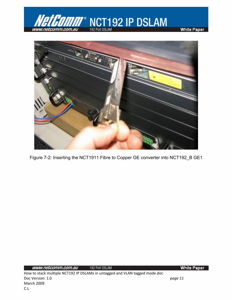
Figure 7-2: Inserting the NCT1911 Fibre to Copper GE converter into NCT192_B GE1
How to stack multiple NCT192 IP DSLAMs in untagged and VLAN tagged mode.docDoc Version: 1.0 page 11 March 2009C.L
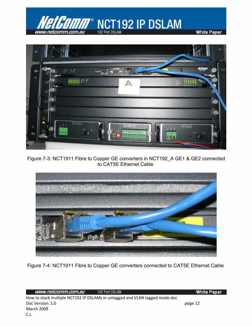
Figure 7-3: NCT1911 Fibre to Copper GE converters in NCT192_A GE1 & GE2 connected to CAT5E Ethernet Cable
Figure 7-4: NCT1911 Fibre to Copper GE converters connected to CAT5E Ethernet Cable
How to stack multiple NCT192 IP DSLAMs in untagged and VLAN tagged mode.docDoc Version: 1.0 page 12 March 2009C.L
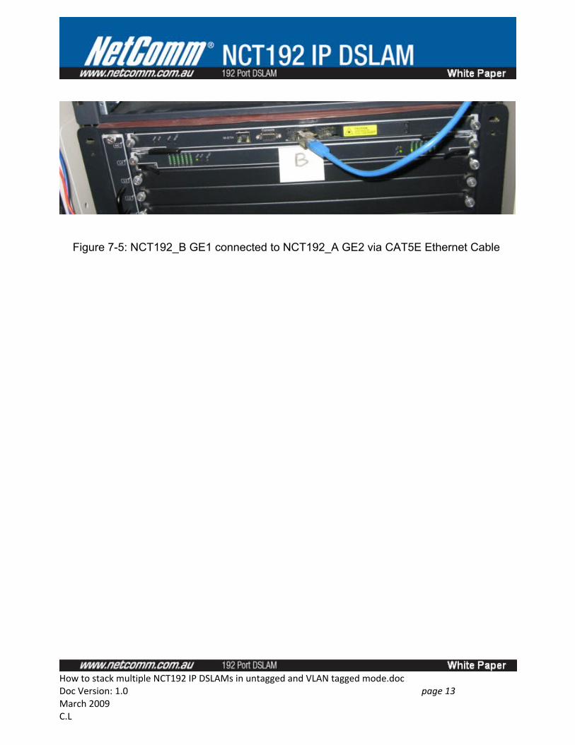
Figure 7-5: NCT192_B GE1 connected to NCT192_A GE2 via CAT5E Ethernet Cable
How to stack multiple NCT192 IP DSLAMs in untagged and VLAN tagged mode.docDoc Version: 1.0 page 13 March 2009C.L
Part 1: How to stack NCT192 IP DSLAM in Untagged Mode
Overview
Part 1 describes the steps and procedure for configuring two NCT192 IP DSLAMs in untagged mode for uni-cast application. The two NCT192 system used are named NCT192_A and NCT192_B. Figure 8 illustrates the logical network diagram used in Part 1. The logical order of configuration described in this section is as follows.
• Configure NCT192_A• Test Modem data throughput from NCT192_A• Configure NCT192_B• Test Modem data throughput from NCT192_B • Connect NCT192_B to NCT192_A• Test Modem data throughput from NCT192_B • Part 1 test complete
There are a total of 25 steps in Part 1. 18 steps were used to configure and test NCT192_A; 6 steps were used to configure and test NCT192_B. 1 step is used to test the data throughput in a stacked NCT192_A and NCT192_B.
Steps 1 to 3 describes how to connect to the NCT192_A’s management interface using LCT. Steps 4 to 6 describe how to initialize line card and network card in NCT192_A. It is recommended to always initializing the Line Card before the Network Card. Steps 7 to 9 describes how to set up ADSL and VLAN profiles in NCT192_A. It also shows how to batch configure the Line Card to map with the profiles. Steps 10 talks about how to configure NCT192_A uplink or downlink interface for system stacking. Steps 11 to 14 describe how to step up secure system management. Steps 15 to 17 describe how to save and back up NCT192_A configuration file. Step 18 describes how to test and view a successful data throughput in NCT192_A.
There is less number of steps used in configuring the NCT192_B because most of the settings were the same. NCT192_B is restored with a NCT192_A’s configuration file followed by small network parameter changes.
How to stack multiple NCT192 IP DSLAMs in untagged and VLAN tagged mode.docDoc Version: 1.0 page 14 March 2009C.L
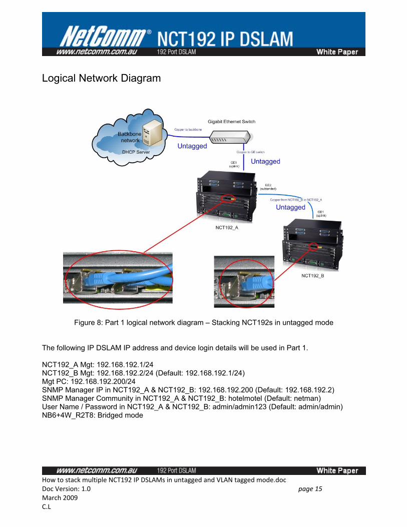
Logical Network Diagram
Figure 8: Part 1 logical network diagram – Stacking NCT192s in untagged mode
The following IP DSLAM IP address and device login details will be used in Part 1.
NCT192_A Mgt: 192.168.192.1/24NCT192_B Mgt: 192.168.192.2/24 (Default: 192.168.192.1/24)Mgt PC: 192.168.192.200/24SNMP Manager IP in NCT192_A & NCT192_B: 192.168.192.200 (Default: 192.168.192.2)SNMP Manager Community in NCT192_A & NCT192_B: hotelmotel (Default: netman)User Name / Password in NCT192_A & NCT192_B: admin/admin123 (Default: admin/admin) NB6+4W_R2T8: Bridged mode
How to stack multiple NCT192 IP DSLAMs in untagged and VLAN tagged mode.docDoc Version: 1.0 page 15 March 2009C.L
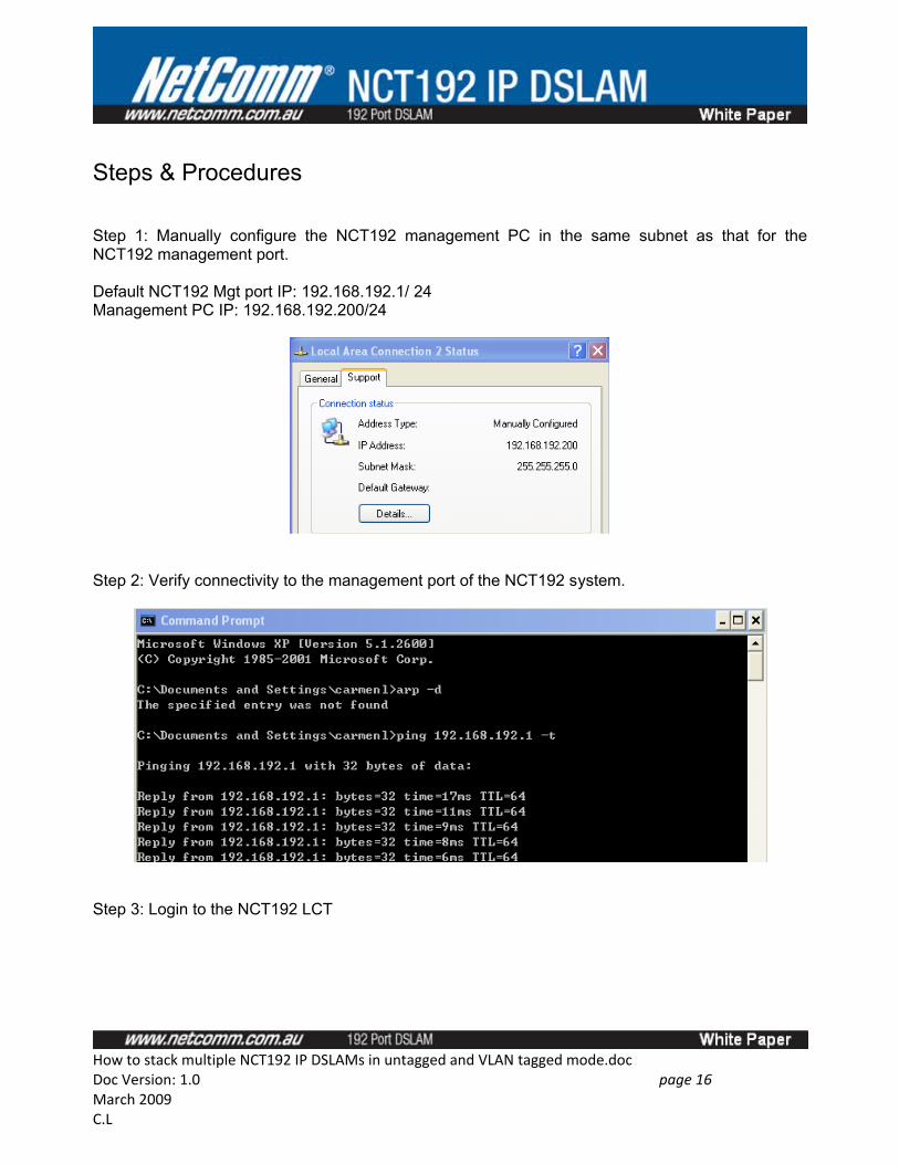
Steps & Procedures
Step 1: Manually configure the NCT192 management PC in the same subnet as that for the NCT192 management port.
Default NCT192 Mgt port IP: 192.168.192.1/ 24Management PC IP: 192.168.192.200/24
Step 2: Verify connectivity to the management port of the NCT192 system.
Step 3: Login to the NCT192 LCT
How to stack multiple NCT192 IP DSLAMs in untagged and VLAN tagged mode.docDoc Version: 1.0 page 16 March 2009C.L
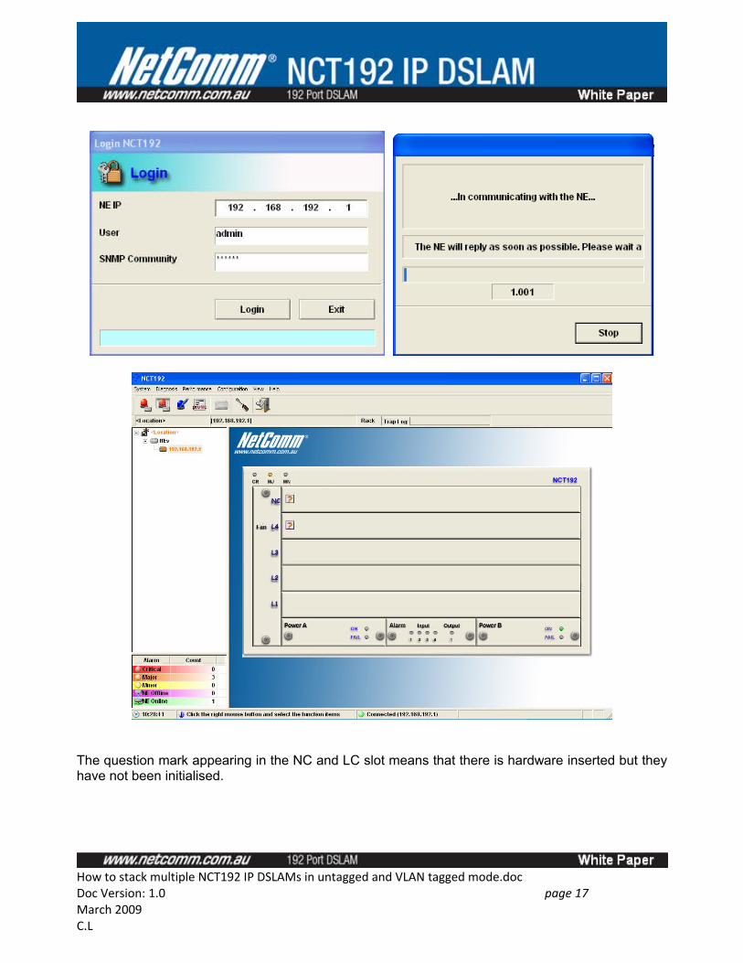
The question mark appearing in the NC and LC slot means that there is hardware inserted but they have not been initialised.
How to stack multiple NCT192 IP DSLAMs in untagged and VLAN tagged mode.docDoc Version: 1.0 page 17 March 2009C.L
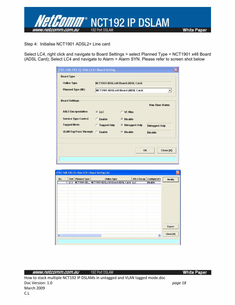
Step 4: Initialise NCT1901 ADSL2+ Line card
Select LC4, right click and navigate to Board Settings > select Planned Type = NCT1901 x48 Board (ADSL Card); Select LC4 and navigate to Alarm > Alarm SYN. Please refer to screen shot below
How to stack multiple NCT192 IP DSLAMs in untagged and VLAN tagged mode.docDoc Version: 1.0 page 18 March 2009C.L
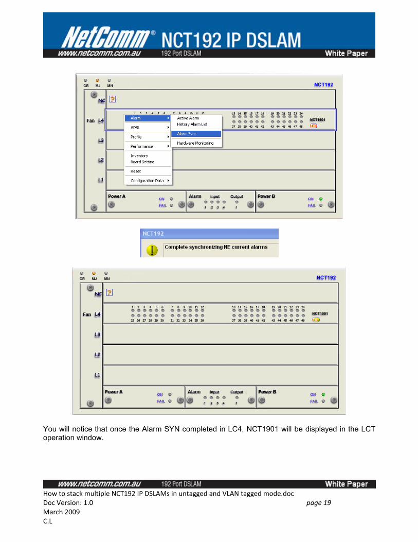
You will notice that once the Alarm SYN completed in LC4, NCT1901 will be displayed in the LCT operation window.
How to stack multiple NCT192 IP DSLAMs in untagged and VLAN tagged mode.docDoc Version: 1.0 page 19 March 2009C.L
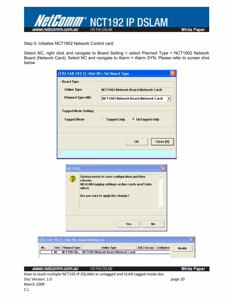
Step 5: Initialise NCT1902 Network Control card
Select NC, right click and navigate to Board Setting > select Planned Type = NCT1902 Network Board (Network Card); Select NC and navigate to Alarm > Alarm SYN. Please refer to screen shot below
How to stack multiple NCT192 IP DSLAMs in untagged and VLAN tagged mode.docDoc Version: 1.0 page 20 March 2009C.L
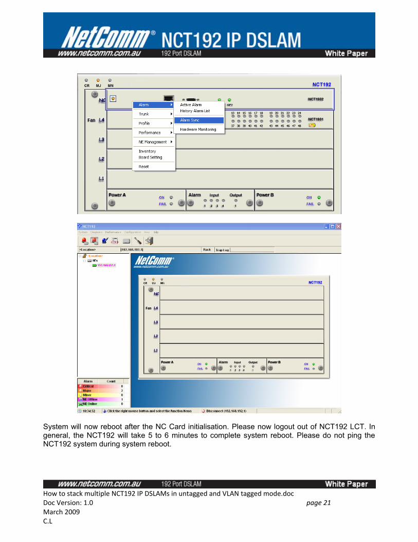
System will now reboot after the NC Card initialisation. Please now logout out of NCT192 LCT. In general, the NCT192 will take 5 to 6 minutes to complete system reboot. Please do not ping the NCT192 system during system reboot.
How to stack multiple NCT192 IP DSLAMs in untagged and VLAN tagged mode.docDoc Version: 1.0 page 21 March 2009C.L
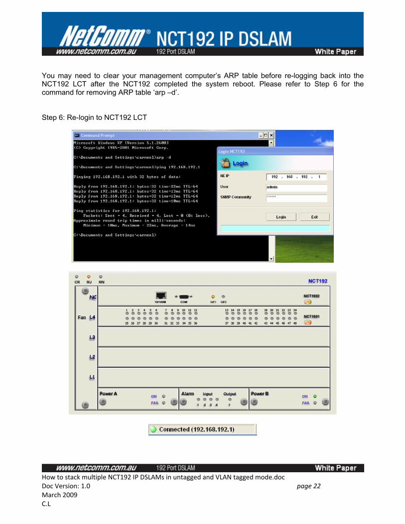
You may need to clear your management computer’s ARP table before re-logging back into the NCT192 LCT after the NCT192 completed the system reboot. Please refer to Step 6 for the command for removing ARP table ‘arp –d’.
Step 6: Re-login to NCT192 LCT
How to stack multiple NCT192 IP DSLAMs in untagged and VLAN tagged mode.docDoc Version: 1.0 page 22 March 2009C.L
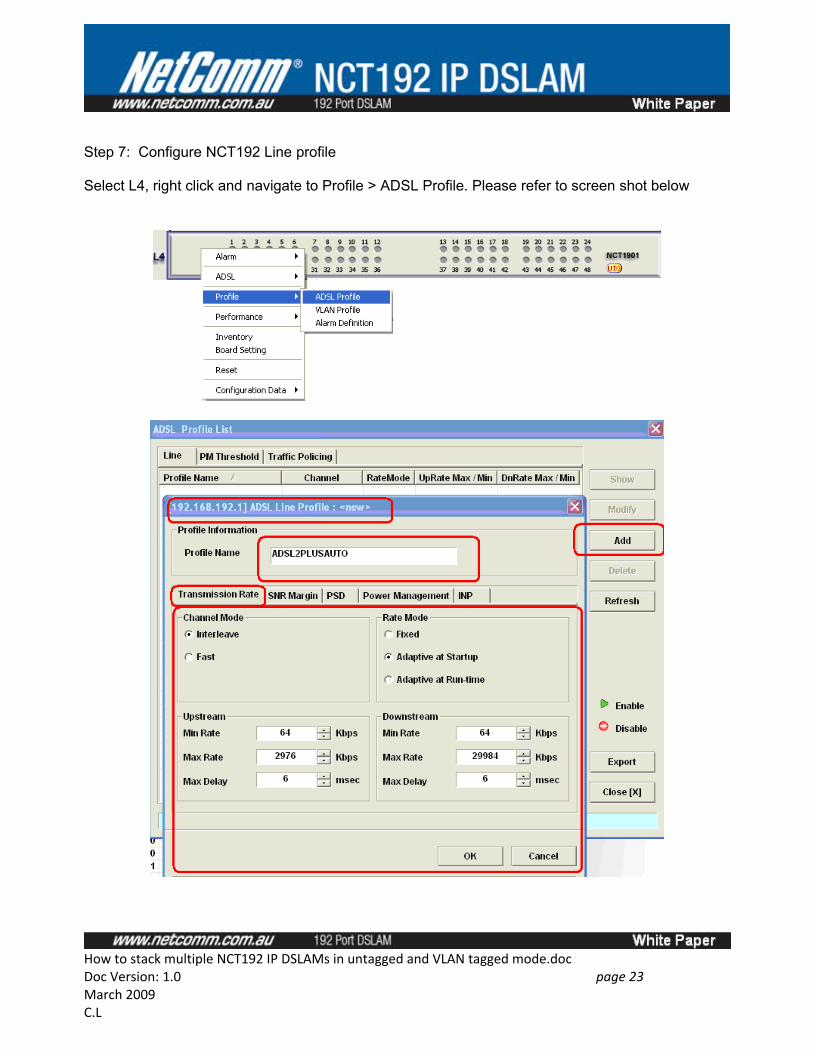
Step 7: Configure NCT192 Line profile
Select L4, right click and navigate to Profile > ADSL Profile. Please refer to screen shot below
How to stack multiple NCT192 IP DSLAMs in untagged and VLAN tagged mode.docDoc Version: 1.0 page 23 March 2009C.L
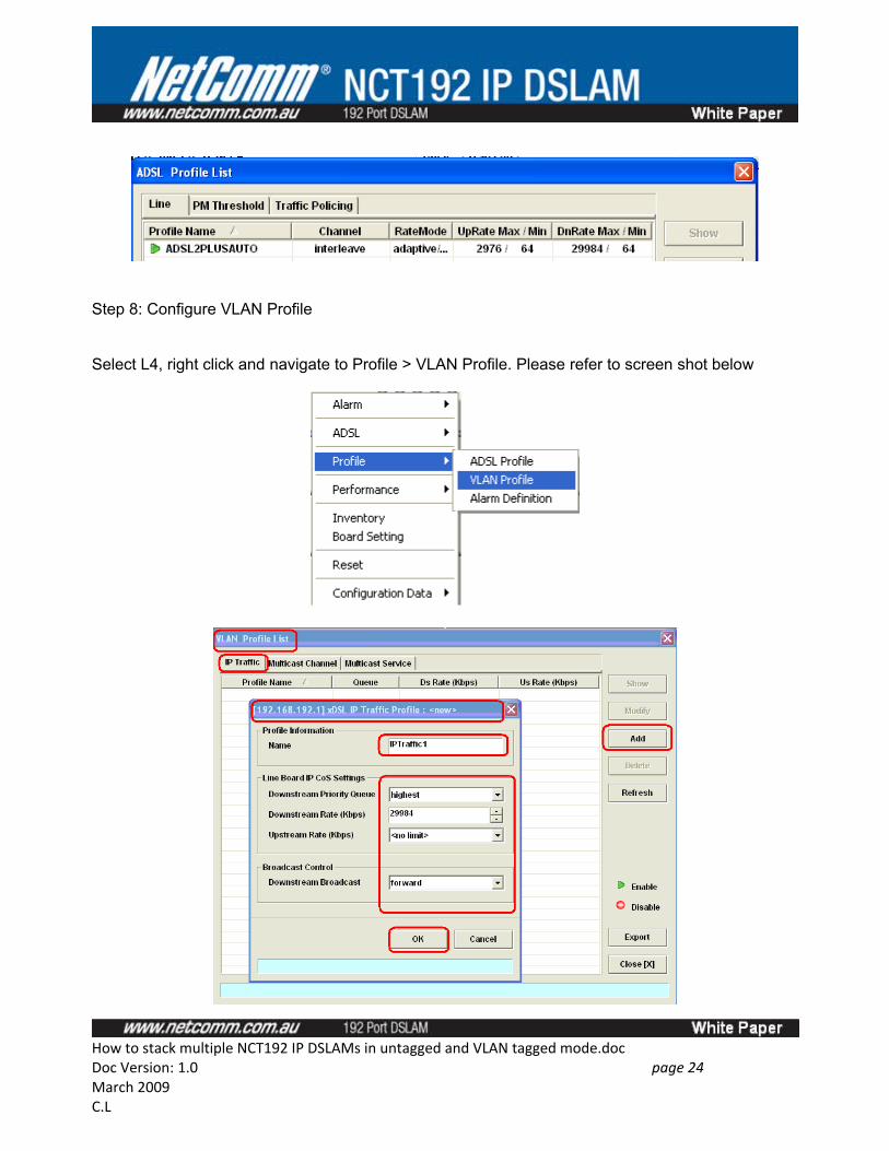
Step 8: Configure VLAN Profile
Select L4, right click and navigate to Profile > VLAN Profile. Please refer to screen shot below
How to stack multiple NCT192 IP DSLAMs in untagged and VLAN tagged mode.docDoc Version: 1.0 page 24 March 2009C.L
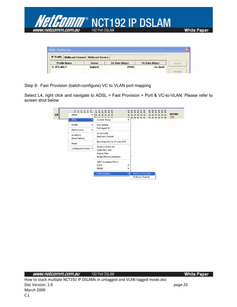
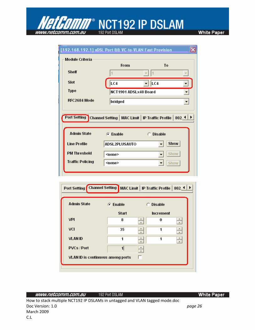
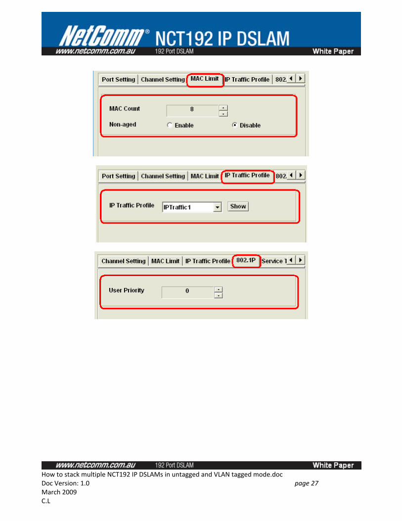
Step 9: Fast Provision (batch-configure) VC to VLAN port mapping
Select L4, right click and navigate to ADSL > Fast Provision > Port & VC-to-VLAN. Please refer to screen shot below
How to stack multiple NCT192 IP DSLAMs in untagged and VLAN tagged mode.docDoc Version: 1.0 page 25 March 2009C.L
How to stack multiple NCT192 IP DSLAMs in untagged and VLAN tagged mode.docDoc Version: 1.0 page 26 March 2009C.L
How to stack multiple NCT192 IP DSLAMs in untagged and VLAN tagged mode.docDoc Version: 1.0 page 27 March 2009C.L
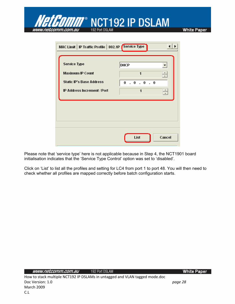
Please note that ‘service type’ here is not applicable because in Step 4, the NCT1901 board initialisation indicates that the ‘Service Type Control’ option was set to ‘disabled’.
Click on ‘List’ to list all the profiles and setting for LC4 from port 1 to port 48. You will then need to check whether all profiles are mapped correctly before batch configuration starts.
How to stack multiple NCT192 IP DSLAMs in untagged and VLAN tagged mode.docDoc Version: 1.0 page 28 March 2009C.L
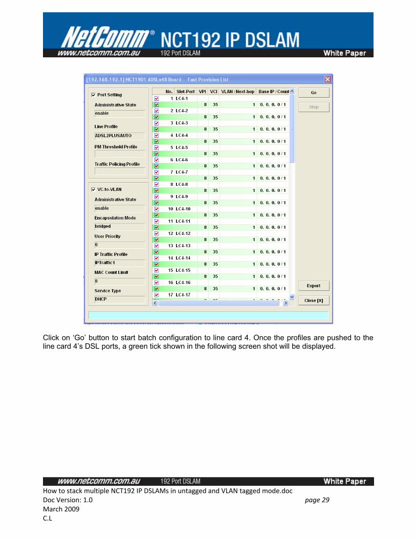
Click on ‘Go’ button to start batch configuration to line card 4. Once the profiles are pushed to the line card 4’s DSL ports, a green tick shown in the following screen shot will be displayed.
How to stack multiple NCT192 IP DSLAMs in untagged and VLAN tagged mode.docDoc Version: 1.0 page 29 March 2009C.L
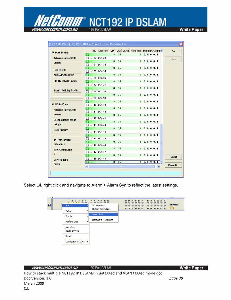
Select L4, right click and navigate to Alarm > Alarm Syn to reflect the latest settings.
How to stack multiple NCT192 IP DSLAMs in untagged and VLAN tagged mode.docDoc Version: 1.0 page 30 March 2009C.L
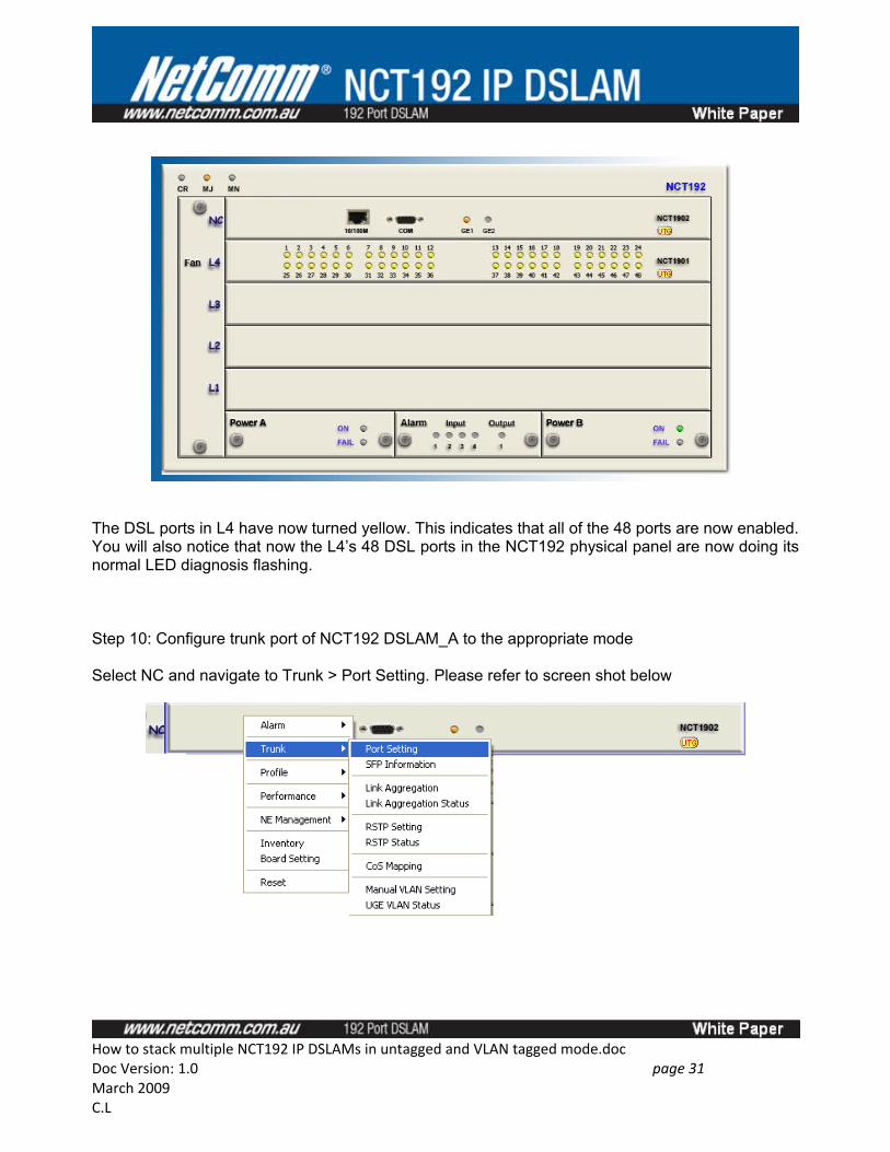
The DSL ports in L4 have now turned yellow. This indicates that all of the 48 ports are now enabled. You will also notice that now the L4’s 48 DSL ports in the NCT192 physical panel are now doing its normal LED diagnosis flashing.
Step 10: Configure trunk port of NCT192 DSLAM_A to the appropriate mode
Select NC and navigate to Trunk > Port Setting. Please refer to screen shot below
How to stack multiple NCT192 IP DSLAMs in untagged and VLAN tagged mode.docDoc Version: 1.0 page 31 March 2009C.L
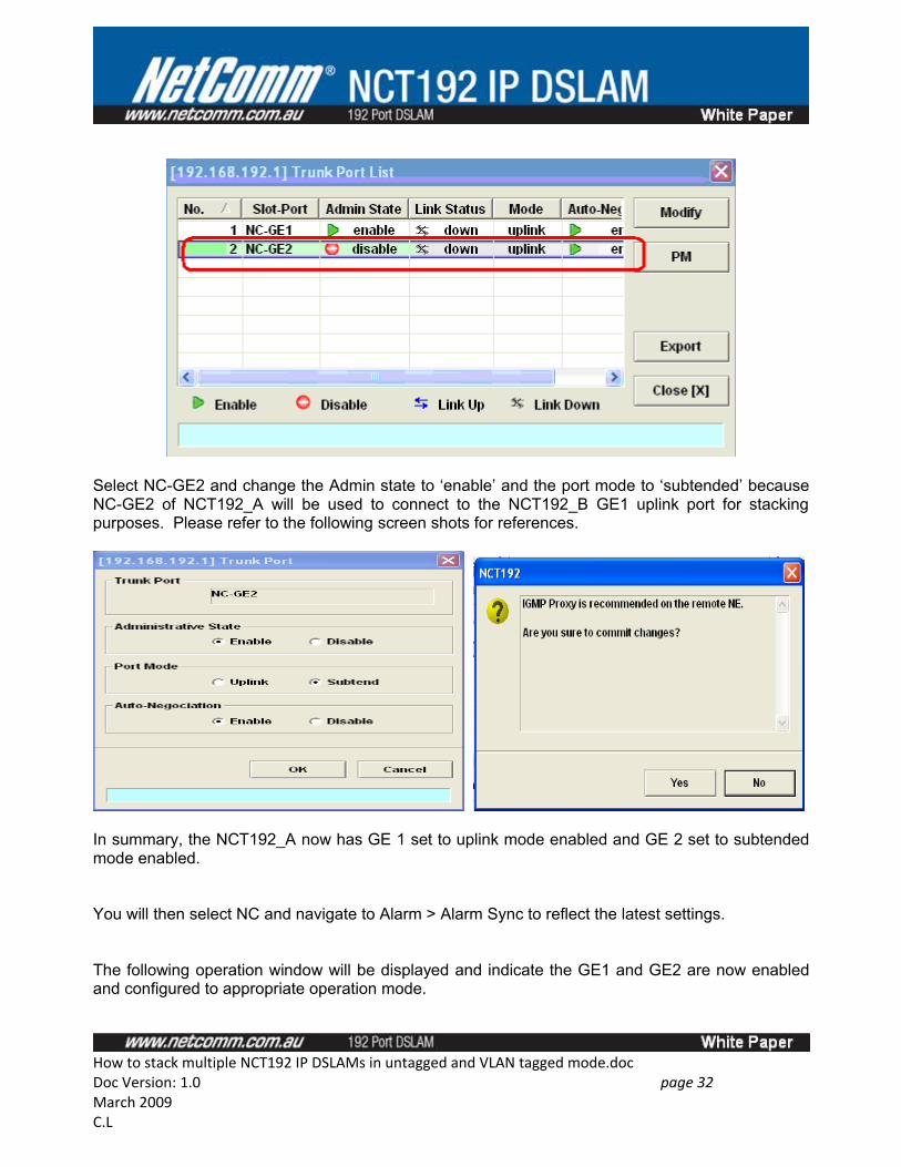
Select NC-GE2 and change the Admin state to ‘enable’ and the port mode to ‘subtended’ because NC-GE2 of NCT192_A will be used to connect to the NCT192_B GE1 uplink port for stacking purposes. Please refer to the following screen shots for references.
In summary, the NCT192_A now has GE 1 set to uplink mode enabled and GE 2 set to subtended mode enabled.
You will then select NC and navigate to Alarm > Alarm Sync to reflect the latest settings.
The following operation window will be displayed and indicate the GE1 and GE2 are now enabled and configured to appropriate operation mode.
How to stack multiple NCT192 IP DSLAMs in untagged and VLAN tagged mode.docDoc Version: 1.0 page 32 March 2009C.L
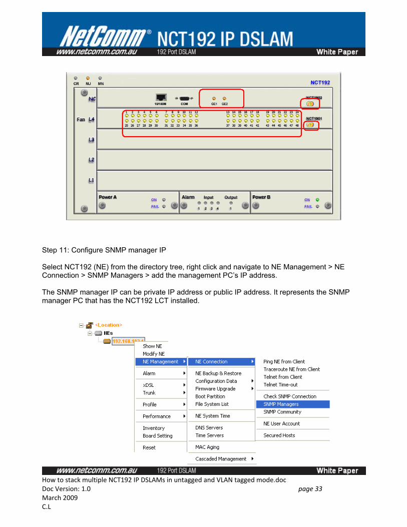
Step 11: Configure SNMP manager IP
Select NCT192 (NE) from the directory tree, right click and navigate to NE Management > NE Connection > SNMP Managers > add the management PC’s IP address.
The SNMP manager IP can be private IP address or public IP address. It represents the SNMP manager PC that has the NCT192 LCT installed.
How to stack multiple NCT192 IP DSLAMs in untagged and VLAN tagged mode.docDoc Version: 1.0 page 33 March 2009C.L
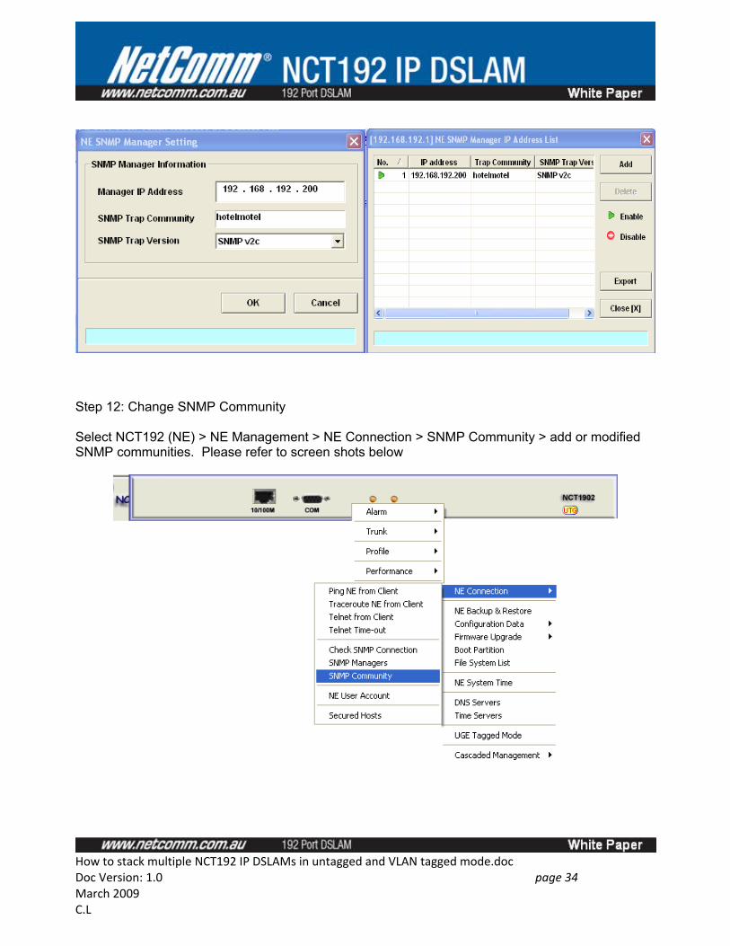
Step 12: Change SNMP Community
Select NCT192 (NE) > NE Management > NE Connection > SNMP Community > add or modified SNMP communities. Please refer to screen shots below
How to stack multiple NCT192 IP DSLAMs in untagged and VLAN tagged mode.docDoc Version: 1.0 page 34 March 2009C.L
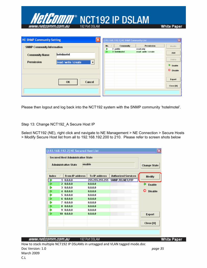
Please then logout and log back into the NCT192 system with the SNMP community ‘hotelmotel’.
Step 13: Change NCT192_A Secure Host IP
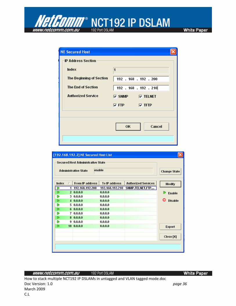
Select NCT192 (NE), right click and navigate to NE Management > NE Connection > Secure Hosts > Modify Secure Host list from all to 192.168.192.200 to 210. Please refer to screen shots below
How to stack multiple NCT192 IP DSLAMs in untagged and VLAN tagged mode.docDoc Version: 1.0 page 35 March 2009C.L
How to stack multiple NCT192 IP DSLAMs in untagged and VLAN tagged mode.docDoc Version: 1.0 page 36 March 2009C.L
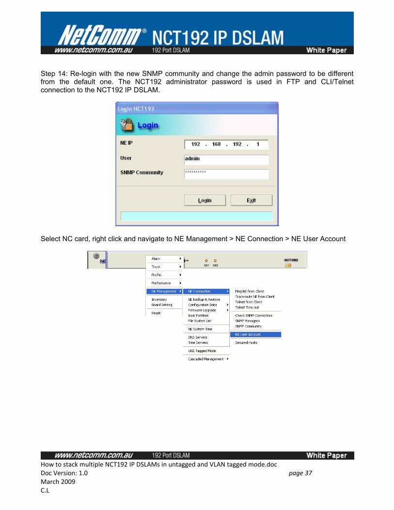
Step 14: Re-login with the new SNMP community and change the admin password to be different from the default one. The NCT192 administrator password is used in FTP and CLI/Telnet connection to the NCT192 IP DSLAM.
Select NC card, right click and navigate to NE Management > NE Connection > NE User Account
How to stack multiple NCT192 IP DSLAMs in untagged and VLAN tagged mode.docDoc Version: 1.0 page 37 March 2009C.L
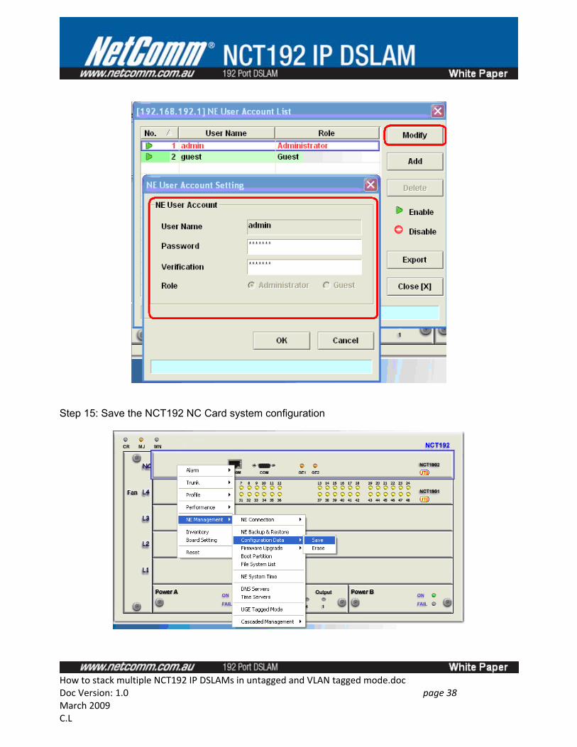
Step 15: Save the NCT192 NC Card system configuration
How to stack multiple NCT192 IP DSLAMs in untagged and VLAN tagged mode.docDoc Version: 1.0 page 38 March 2009C.L
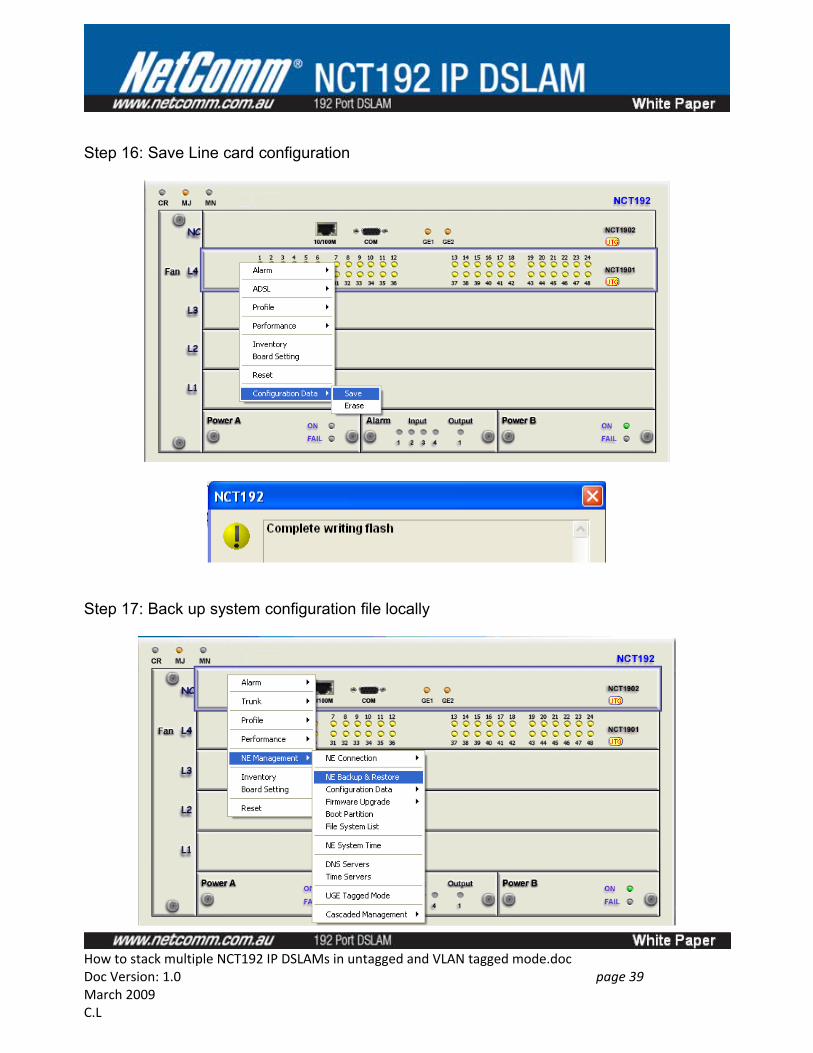
Step 16: Save Line card configuration
Step 17: Back up system configuration file locally
How to stack multiple NCT192 IP DSLAMs in untagged and VLAN tagged mode.docDoc Version: 1.0 page 39 March 2009C.L
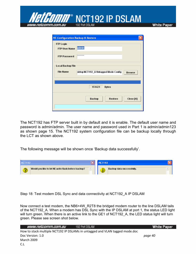
The NCT192 has FTP server built in by default and it is enable. The default user name and password is admin/admin. The user name and password used in Part 1 is admin/admin123 as shown page 15. The NCT192 system configuration file can be backup locally through the LCT as shown above.
The following message will be shown once ‘Backup data successfully’.
Step 18: Test modem DSL Sync and data connectivity at NCT192_A IP DSLAM
Now connect a test modem, the NB6+4W_R2T8 the bridged modem router to the line DSLAM tails of the NCT192_A. When a modem has DSL Sync with the IP DSLAM at port 1, the status LED light will turn green. When there is an active link to the GE1 of NCT192_A, the LED status light will turn green. Please see screen shot below.
How to stack multiple NCT192 IP DSLAMs in untagged and VLAN tagged mode.docDoc Version: 1.0 page 40 March 2009C.L
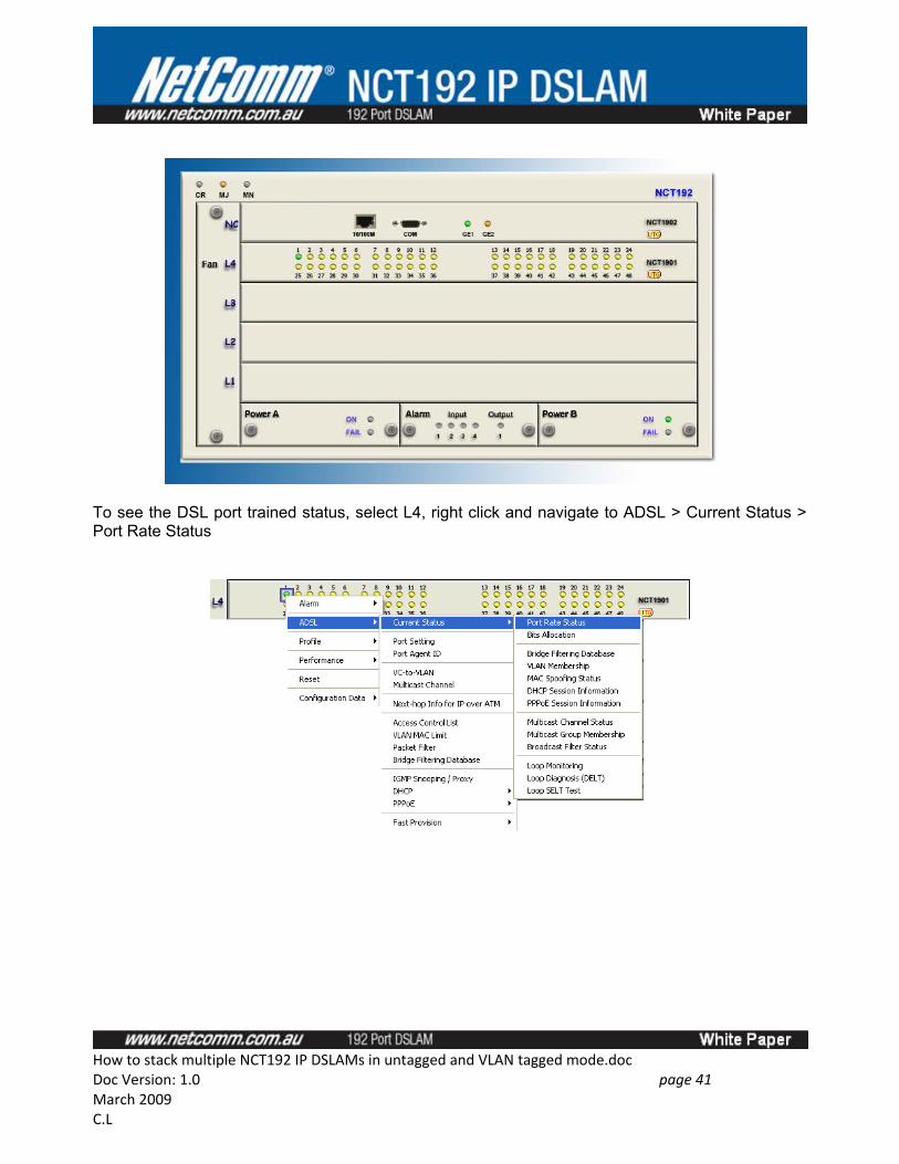
To see the DSL port trained status, select L4, right click and navigate to ADSL > Current Status > Port Rate Status
How to stack multiple NCT192 IP DSLAMs in untagged and VLAN tagged mode.docDoc Version: 1.0 page 41 March 2009C.L
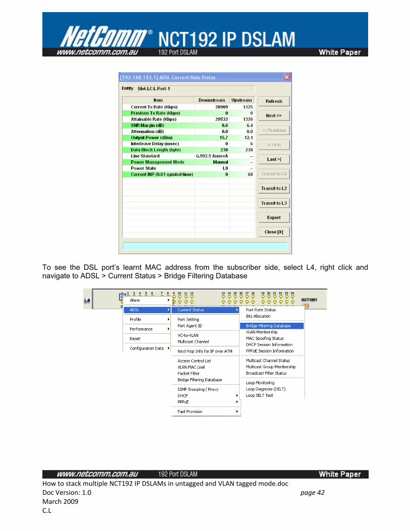
To see the DSL port’s learnt MAC address from the subscriber side, select L4, right click and navigate to ADSL > Current Status > Bridge Filtering Database
How to stack multiple NCT192 IP DSLAMs in untagged and VLAN tagged mode.docDoc Version: 1.0 page 42 March 2009C.L
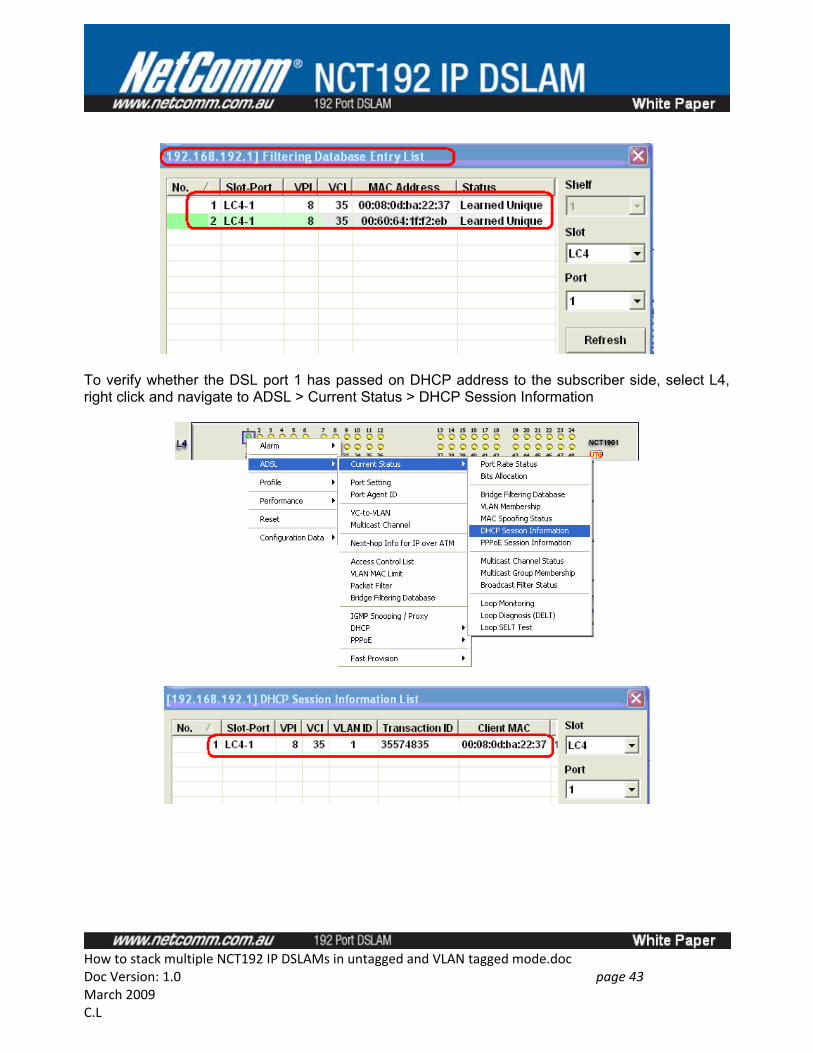
To verify whether the DSL port 1 has passed on DHCP address to the subscriber side, select L4, right click and navigate to ADSL > Current Status > DHCP Session Information
How to stack multiple NCT192 IP DSLAMs in untagged and VLAN tagged mode.docDoc Version: 1.0 page 43 March 2009C.L
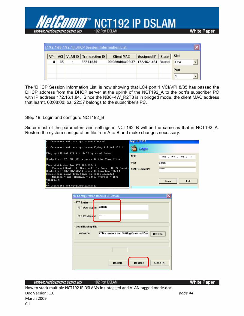
The ‘DHCP Session Information List’ is now showing that LC4 port 1 VCI/VPI 8/35 has passed the DHCP address from the DHCP server at the uplink of the NCT192_A to the port’s subscriber PC with IP address 172.16.1.84. Since the NB6+4W_R2T8 is in bridged mode, the client MAC address that learnt, 00:08:0d: ba: 22:37 belongs to the subscriber’s PC.
Step 19: Login and configure NCT192_B
Since most of the parameters and settings in NCT192_B will be the same as that in NCT192_A. Restore the system configuration file from A to B and make changes necessary.
How to stack multiple NCT192 IP DSLAMs in untagged and VLAN tagged mode.docDoc Version: 1.0 page 44 March 2009C.L
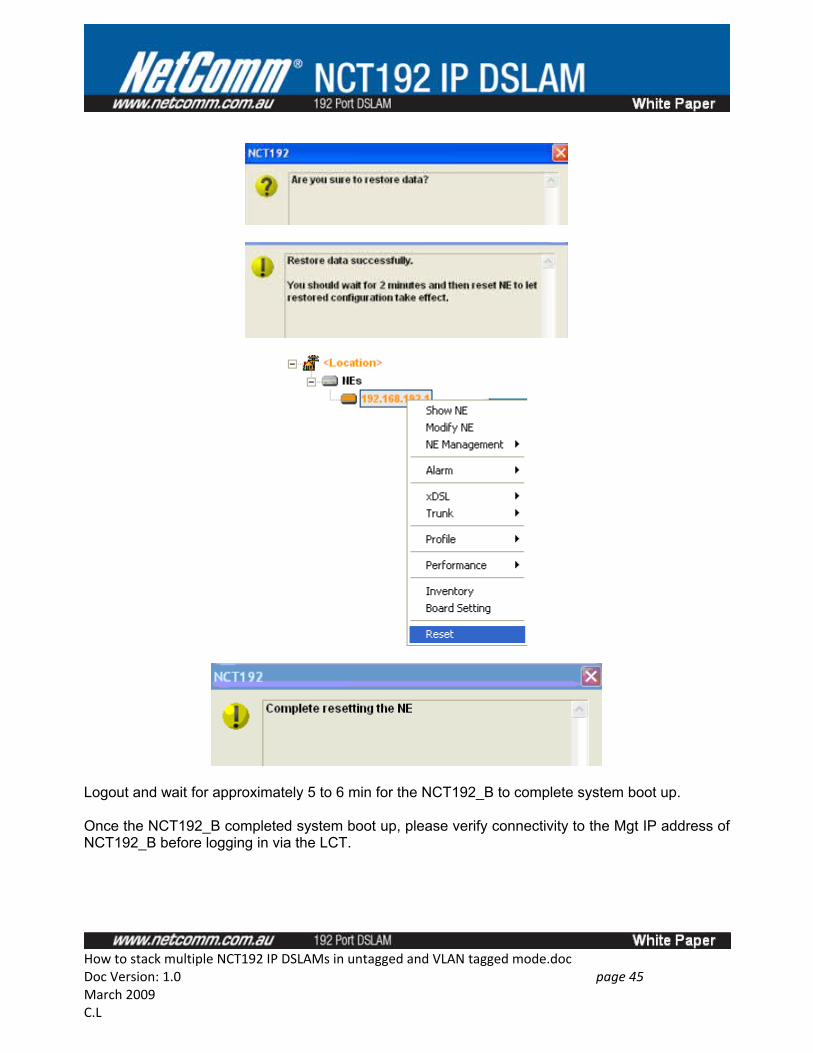
Logout and wait for approximately 5 to 6 min for the NCT192_B to complete system boot up.
Once the NCT192_B completed system boot up, please verify connectivity to the Mgt IP address of NCT192_B before logging in via the LCT.
How to stack multiple NCT192 IP DSLAMs in untagged and VLAN tagged mode.docDoc Version: 1.0 page 45 March 2009C.L
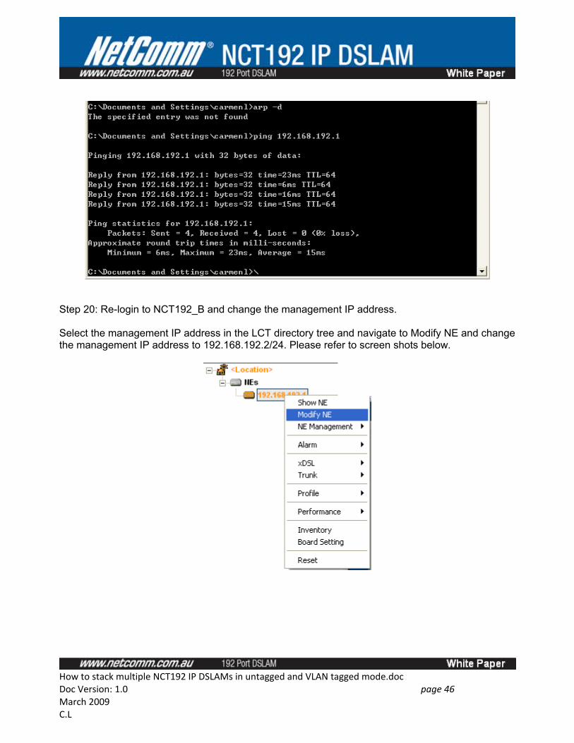
Step 20: Re-login to NCT192_B and change the management IP address.
Select the management IP address in the LCT directory tree and navigate to Modify NE and change the management IP address to 192.168.192.2/24. Please refer to screen shots below.
How to stack multiple NCT192 IP DSLAMs in untagged and VLAN tagged mode.docDoc Version: 1.0 page 46 March 2009C.L
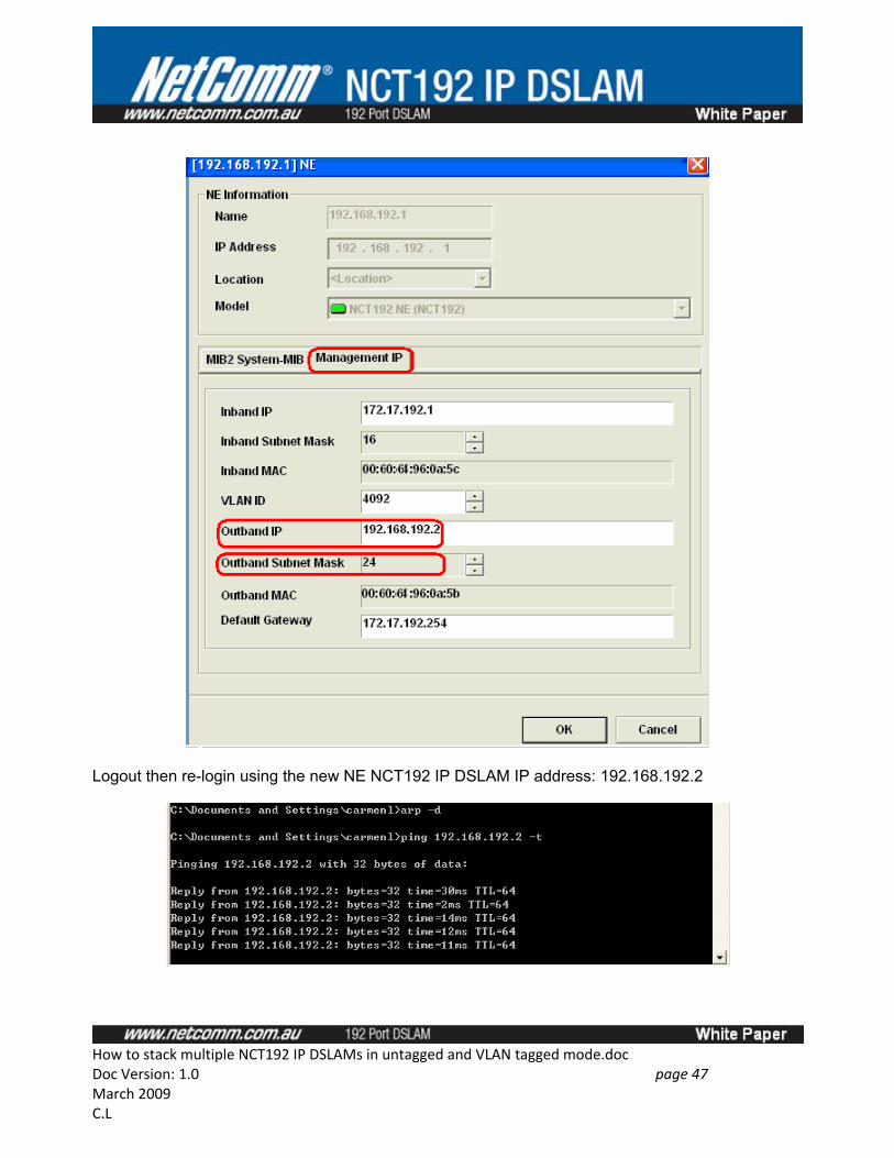
Logout then re-login using the new NE NCT192 IP DSLAM IP address: 192.168.192.2
How to stack multiple NCT192 IP DSLAMs in untagged and VLAN tagged mode.docDoc Version: 1.0 page 47 March 2009C.L
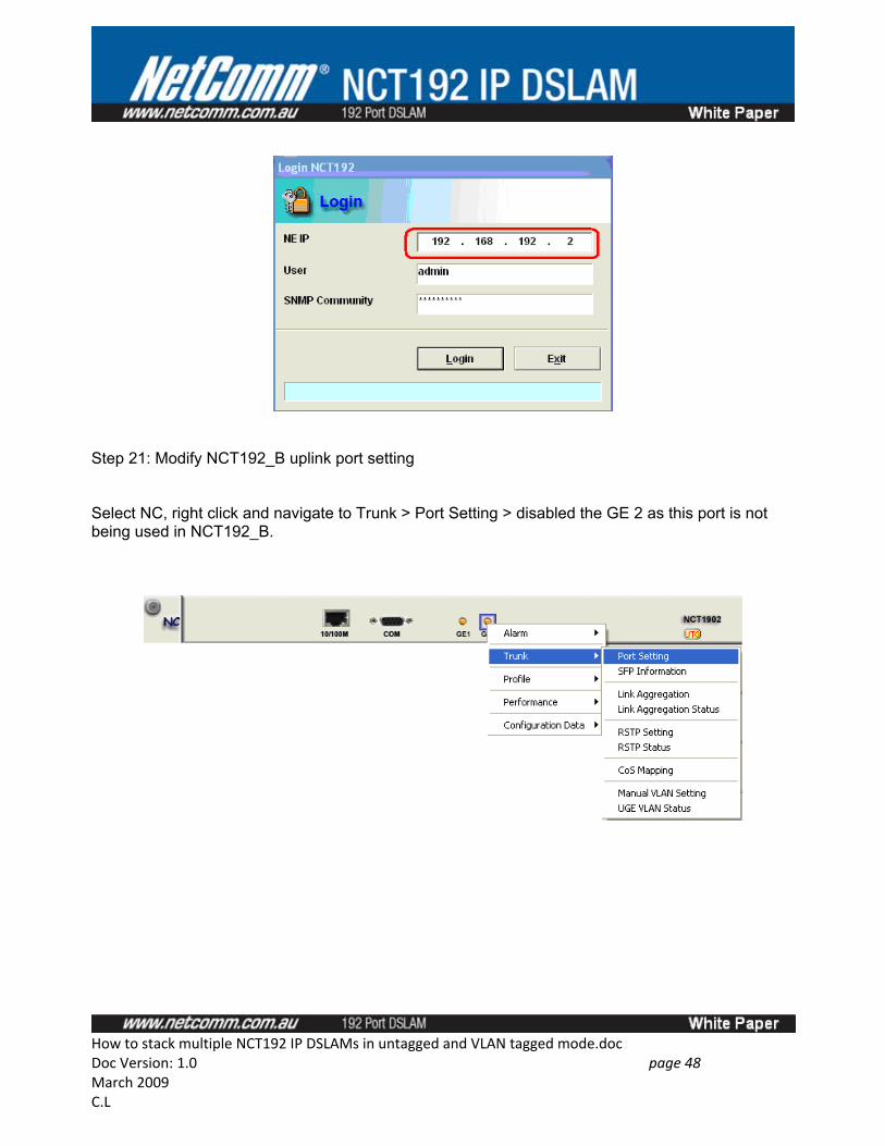
Step 21: Modify NCT192_B uplink port setting
Select NC, right click and navigate to Trunk > Port Setting > disabled the GE 2 as this port is not being used in NCT192_B.
How to stack multiple NCT192 IP DSLAMs in untagged and VLAN tagged mode.docDoc Version: 1.0 page 48 March 2009C.L
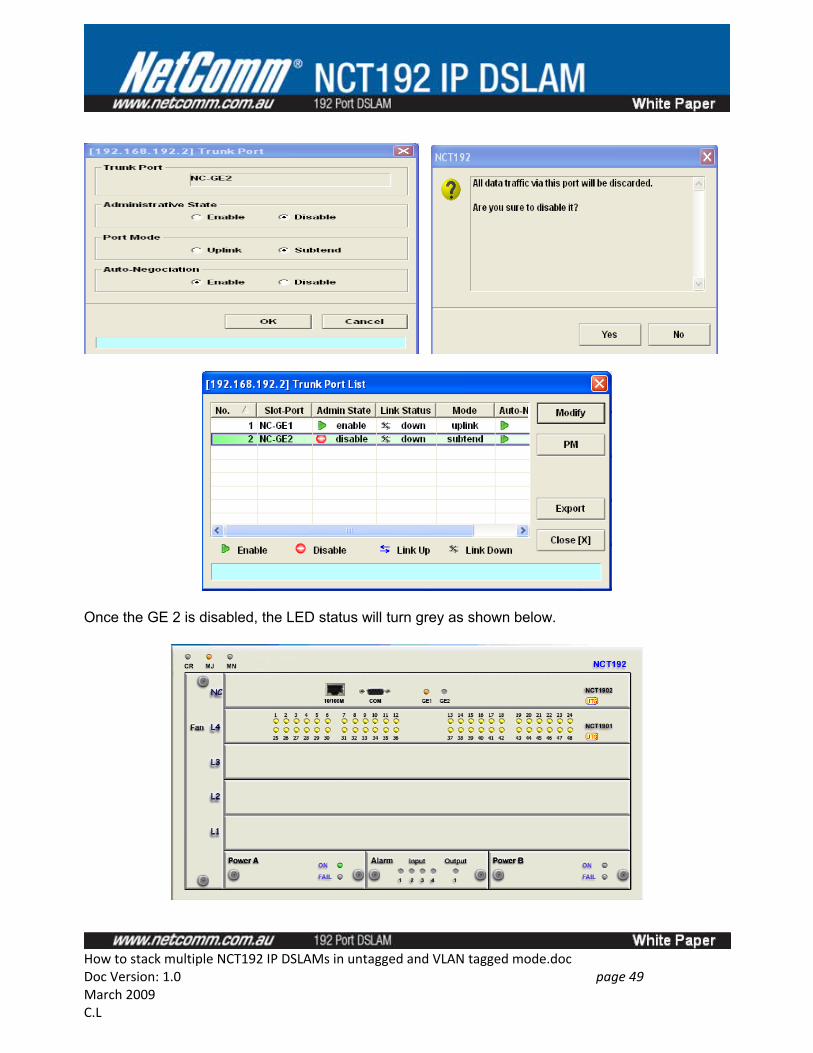
Once the GE 2 is disabled, the LED status will turn grey as shown below.
How to stack multiple NCT192 IP DSLAMs in untagged and VLAN tagged mode.docDoc Version: 1.0 page 49 March 2009C.L
Step 22: Save NCT192_B NC Card and LC card configuration.
Step 23: Backup NCT192_B Configuration.
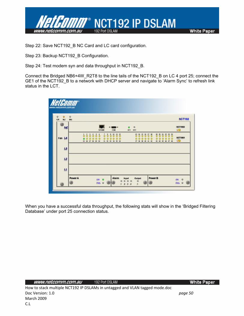
Step 24: Test modem syn and data throughput in NCT192_B.
Connect the Bridged NB6+4W_R2T8 to the line tails of the NCT192_B on LC 4 port 25; connect the GE1 of the NCT192_B to a network with DHCP server and navigate to ‘Alarm Sync’ to refresh link status in the LCT.
When you have a successful data throughput, the following stats will show in the ‘Bridged Filtering Database’ under port 25 connection status.
How to stack multiple NCT192 IP DSLAMs in untagged and VLAN tagged mode.docDoc Version: 1.0 page 50 March 2009C.L
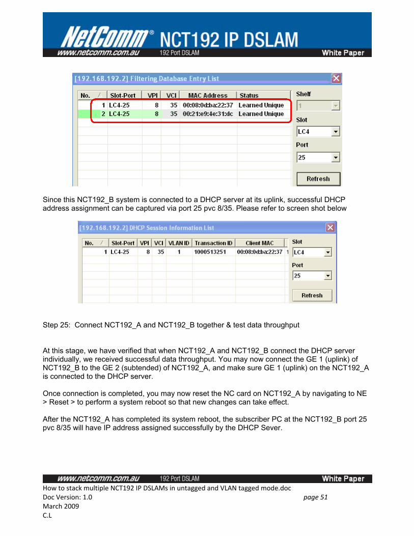
Since this NCT192_B system is connected to a DHCP server at its uplink, successful DHCP address assignment can be captured via port 25 pvc 8/35. Please refer to screen shot below
Step 25: Connect NCT192_A and NCT192_B together & test data throughput
At this stage, we have verified that when NCT192_A and NCT192_B connect the DHCP server individually, we received successful data throughput. You may now connect the GE 1 (uplink) of NCT192_B to the GE 2 (subtended) of NCT192_A, and make sure GE 1 (uplink) on the NCT192_A is connected to the DHCP server.
Once connection is completed, you may now reset the NC card on NCT192_A by navigating to NE > Reset > to perform a system reboot so that new changes can take effect.
After the NCT192_A has completed its system reboot, the subscriber PC at the NCT192_B port 25 pvc 8/35 will have IP address assigned successfully by the DHCP Sever.
How to stack multiple NCT192 IP DSLAMs in untagged and VLAN tagged mode.docDoc Version: 1.0 page 51 March 2009C.L
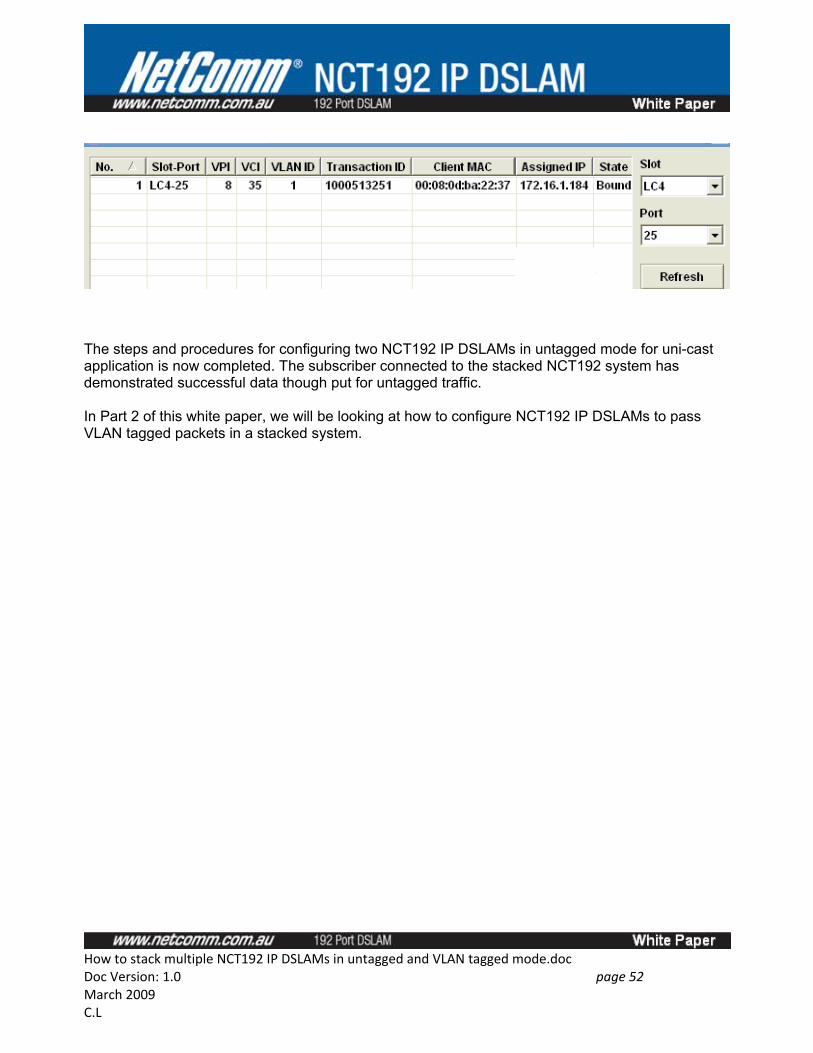
The steps and procedures for configuring two NCT192 IP DSLAMs in untagged mode for uni-cast application is now completed. The subscriber connected to the stacked NCT192 system has demonstrated successful data though put for untagged traffic.
In Part 2 of this white paper, we will be looking at how to configure NCT192 IP DSLAMs to pass VLAN tagged packets in a stacked system.
How to stack multiple NCT192 IP DSLAMs in untagged and VLAN tagged mode.docDoc Version: 1.0 page 52 March 2009C.L
Part 2: How to stack NCT192 IP DSLAM in VLAN Tagged Mode
Overview
Part 2 describes the steps and procedure for configuring two NCT192 IP DSLAMs in VLAN tagged mode for uni-cast application. Part 2 of this white paper is built-upon the completion of Part 1 where the same ADSL profile and GE port mode settings will be used. You will notice that there is less number of steps involved because it is assumed that the configurations made in Part 1 were kept in the two IP DSLAMs. The only changes to be made to NCT192_A and B are the global VLAN mode and the DSL port’s VC-to-VLAN configuration.
The two NCT192 system used are stilled named NCT192_A and NCT192_B in this section. Figure 9 illustrates the logical network diagram used Part 2. There are a total of 14 steps described in part 2. The logical order of configuration described is as follows.
• Configure NCT192_B DSL and GE interface VLANs• Test Modem data throughput from NCT192_A• Configure NCT192_A DSL and GE interfaces VLANs• Test Modem data throughput from NCT192_B • Connect NCT192_B to NCT192_A• Test Modem data throughput from NCT192_B • Part 2 test complete
It is generally recommended to start with the IP DSLAM that kept the least number of VLAN database and work its way up, hence the steps shown in this section are started with configuration in NCT192_B IP DSLAM.
The following VLAN numbers are assigned to NCT192_B.
LC4: Port 1 (VLAN 301), Port 2 (VLAN 302); . . . Port 48 (VLAN 348). GE 1: VLAN 301 to 348 802.1Q Tagged GE 2: (disabled) NC card: Tagged Mode
The following VLAN numbers are assigned to NCT192_A
LC4: Port 1 (VLAN 101), Port 2 (VLAN 102); . . . Port 48 (VLAN 148). GE 1: VLAN 101 to 148 VLAN Tagged; VLAN 301 to 348 (VLAN Tagged) GE 2: VLAN 101 to 148 VLAN Tagged; VLAN 301 to 348 (VLAN Tagged) NC card: Tagged Mode
How to stack multiple NCT192 IP DSLAMs in untagged and VLAN tagged mode.docDoc Version: 1.0 page 53 March 2009C.L
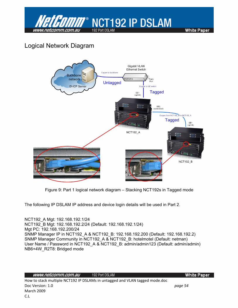
Logical Network Diagram
Figure 9: Part 1 logical network diagram – Stacking NCT192s in Tagged mode
The following IP DSLAM IP address and device login details will be used in Part 2.
NCT192_A Mgt: 192.168.192.1/24NCT192_B Mgt: 192.168.192.2/24 (Default: 192.168.192.1/24)Mgt PC: 192.168.192.200/24SNMP Manager IP in NCT192_A & NCT192_B: 192.168.192.200 (Default: 192.168.192.2)SNMP Manager Community in NCT192_A & NCT192_B: hotelmotel (Default: netman)User Name / Password in NCT192_A & NCT192_B: admin/admin123 (Default: admin/admin) NB6+4W_R2T8: Bridged mode
How to stack multiple NCT192 IP DSLAMs in untagged and VLAN tagged mode.docDoc Version: 1.0 page 54 March 2009C.L
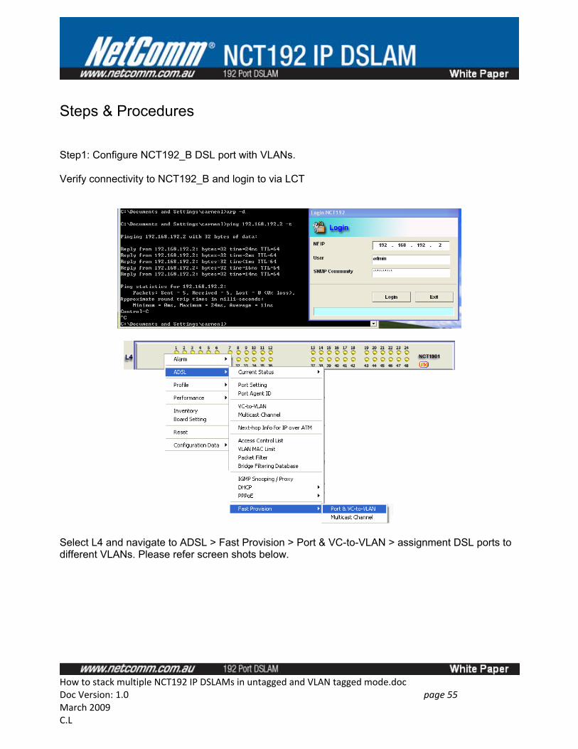
Steps & Procedures
Step1: Configure NCT192_B DSL port with VLANs.
Verify connectivity to NCT192_B and login to via LCT
Select L4 and navigate to ADSL > Fast Provision > Port & VC-to-VLAN > assignment DSL ports to different VLANs. Please refer screen shots below.
How to stack multiple NCT192 IP DSLAMs in untagged and VLAN tagged mode.docDoc Version: 1.0 page 55 March 2009C.L
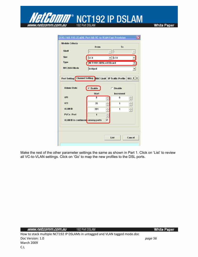
Make the rest of the other parameter settings the same as shown in Part 1. Click on ‘List’ to review all VC-to-VLAN settings. Click on ‘Go’ to map the new profiles to the DSL ports.
How to stack multiple NCT192 IP DSLAMs in untagged and VLAN tagged mode.docDoc Version: 1.0 page 56 March 2009C.L
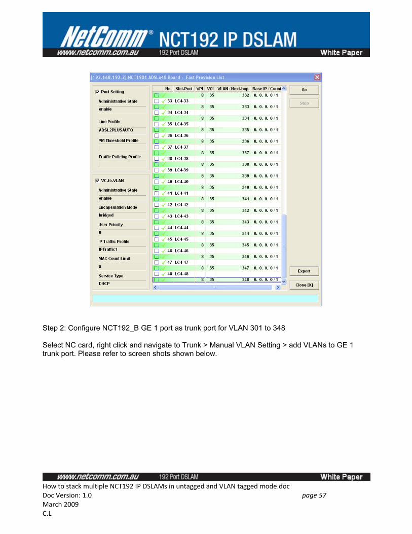
Step 2: Configure NCT192_B GE 1 port as trunk port for VLAN 301 to 348
Select NC card, right click and navigate to Trunk > Manual VLAN Setting > add VLANs to GE 1 trunk port. Please refer to screen shots shown below.
How to stack multiple NCT192 IP DSLAMs in untagged and VLAN tagged mode.docDoc Version: 1.0 page 57 March 2009C.L
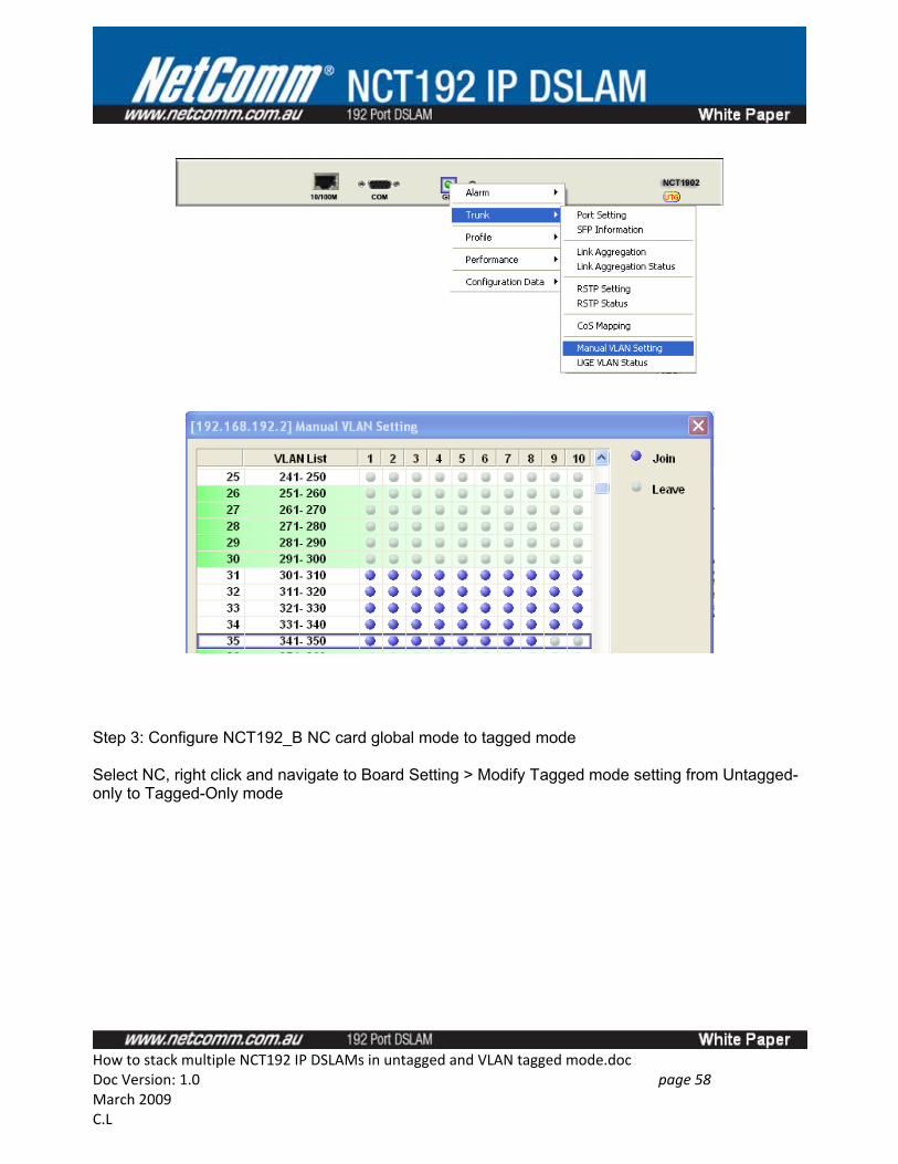
Step 3: Configure NCT192_B NC card global mode to tagged mode
Select NC, right click and navigate to Board Setting > Modify Tagged mode setting from Untagged-only to Tagged-Only mode
How to stack multiple NCT192 IP DSLAMs in untagged and VLAN tagged mode.docDoc Version: 1.0 page 58 March 2009C.L
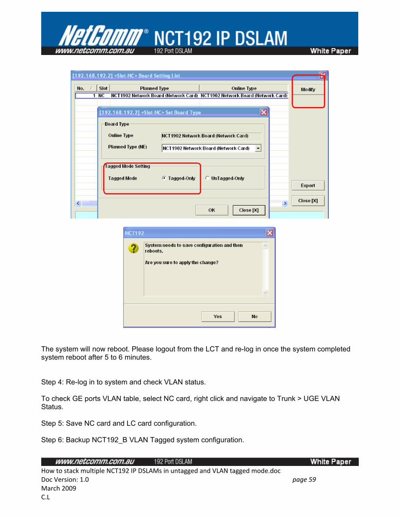
The system will now reboot. Please logout from the LCT and re-log in once the system completed system reboot after 5 to 6 minutes.
Step 4: Re-log in to system and check VLAN status.
To check GE ports VLAN table, select NC card, right click and navigate to Trunk > UGE VLAN Status.
Step 5: Save NC card and LC card configuration.
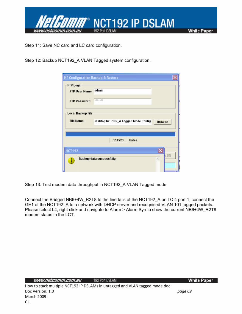
Step 6: Backup NCT192_B VLAN Tagged system configuration.
How to stack multiple NCT192 IP DSLAMs in untagged and VLAN tagged mode.docDoc Version: 1.0 page 59 March 2009C.L
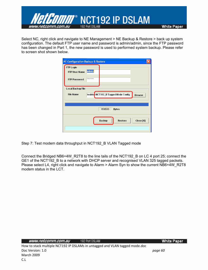
Select NC, right click and navigate to NE Management > NE Backup & Restore > back up system configuration. The default FTP user name and password is admin/admin, since the FTP password has been changed in Part 1, the new password is used to performed system backup. Please refer to screen shot shown below.
Step 7: Test modem data throughput in NCT192_B VLAN Tagged mode
Connect the Bridged NB6+4W_R2T8 to the line tails of the NCT192_B on LC 4 port 25; connect the GE1 of the NCT192_B to a network with DHCP server and recognised VLAN 325 tagged packets. Please select L4, right click and navigate to Alarm > Alarm Syn to show the current NB6+4W_R2T8 modem status in the LCT.
How to stack multiple NCT192 IP DSLAMs in untagged and VLAN tagged mode.docDoc Version: 1.0 page 60 March 2009C.L
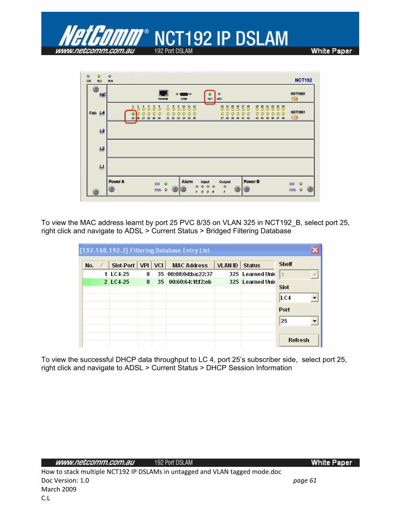
To view the MAC address learnt by port 25 PVC 8/35 on VLAN 325 in NCT192_B, select port 25, right click and navigate to ADSL > Current Status > Bridged Filtering Database
To view the successful DHCP data throughput to LC 4, port 25’s subscriber side, select port 25, right click and navigate to ADSL > Current Status > DHCP Session Information
How to stack multiple NCT192 IP DSLAMs in untagged and VLAN tagged mode.docDoc Version: 1.0 page 61 March 2009C.L
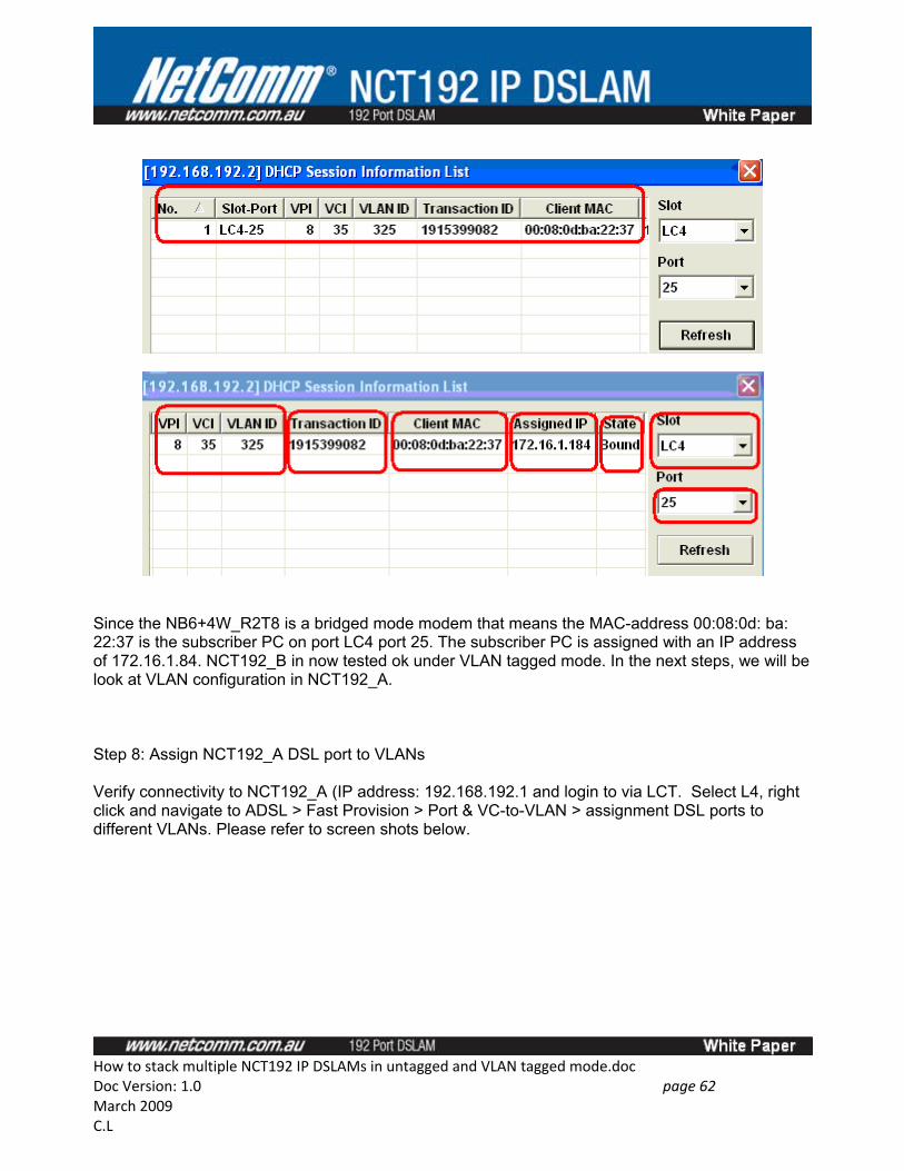
Since the NB6+4W_R2T8 is a bridged mode modem that means the MAC-address 00:08:0d: ba: 22:37 is the subscriber PC on port LC4 port 25. The subscriber PC is assigned with an IP address of 172.16.1.84. NCT192_B in now tested ok under VLAN tagged mode. In the next steps, we will be look at VLAN configuration in NCT192_A.
Step 8: Assign NCT192_A DSL port to VLANs
Verify connectivity to NCT192_A (IP address: 192.168.192.1 and login to via LCT. Select L4, right click and navigate to ADSL > Fast Provision > Port & VC-to-VLAN > assignment DSL ports to different VLANs. Please refer to screen shots below.
How to stack multiple NCT192 IP DSLAMs in untagged and VLAN tagged mode.docDoc Version: 1.0 page 62 March 2009C.L
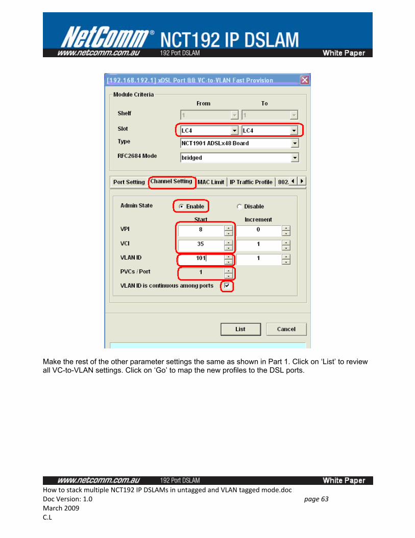
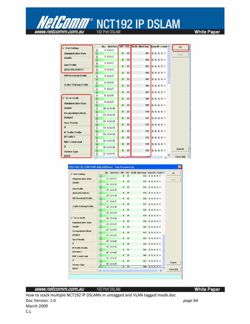
Make the rest of the other parameter settings the same as shown in Part 1. Click on ‘List’ to review all VC-to-VLAN settings. Click on ‘Go’ to map the new profiles to the DSL ports.
How to stack multiple NCT192 IP DSLAMs in untagged and VLAN tagged mode.docDoc Version: 1.0 page 63 March 2009C.L
How to stack multiple NCT192 IP DSLAMs in untagged and VLAN tagged mode.docDoc Version: 1.0 page 64 March 2009C.L
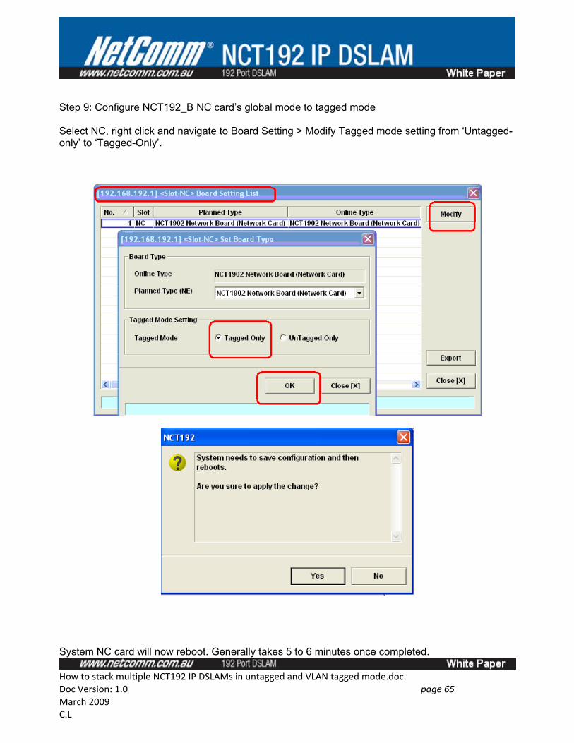
Step 9: Configure NCT192_B NC card’s global mode to tagged mode
Select NC, right click and navigate to Board Setting > Modify Tagged mode setting from ‘Untagged-only’ to ‘Tagged-Only’.
System NC card will now reboot. Generally takes 5 to 6 minutes once completed.
How to stack multiple NCT192 IP DSLAMs in untagged and VLAN tagged mode.docDoc Version: 1.0 page 65 March 2009C.L
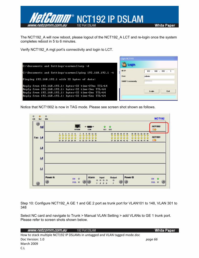
The NCT192_A will now reboot, please logout of the NCT192_A LCT and re-login once the system completes reboot in 5 to 6 minutes.
Verify NCT192_A mgt port’s connectivity and login to LCT.
Notice that NCT1902 is now in TAG mode. Please see screen shot shown as follows.
Step 10: Configure NCT192_A GE 1 and GE 2 port as trunk port for VLAN101 to 148, VLAN 301 to 348
Select NC card and navigate to Trunk > Manual VLAN Setting > add VLANs to GE 1 trunk port. Please refer to screen shots shown below.
How to stack multiple NCT192 IP DSLAMs in untagged and VLAN tagged mode.docDoc Version: 1.0 page 66 March 2009C.L
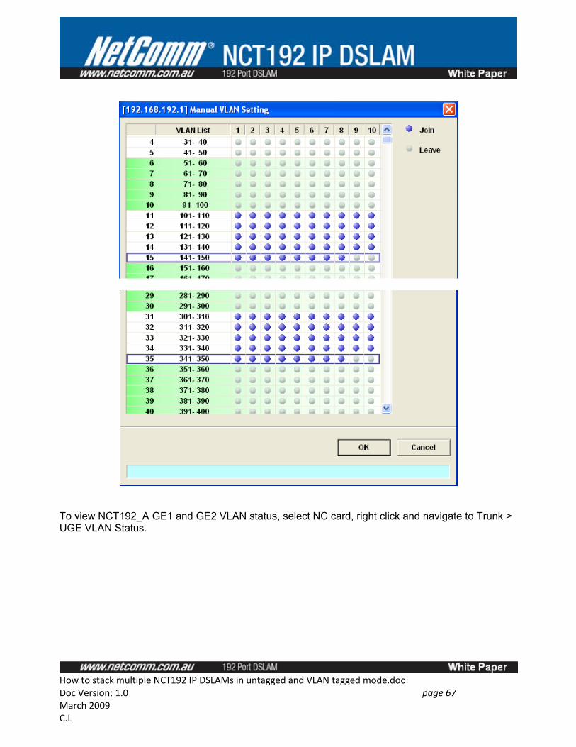
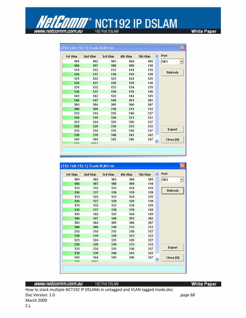
To view NCT192_A GE1 and GE2 VLAN status, select NC card, right click and navigate to Trunk > UGE VLAN Status.
How to stack multiple NCT192 IP DSLAMs in untagged and VLAN tagged mode.docDoc Version: 1.0 page 67 March 2009C.L
How to stack multiple NCT192 IP DSLAMs in untagged and VLAN tagged mode.docDoc Version: 1.0 page 68 March 2009C.L
Step 11: Save NC card and LC card configuration.
Step 12: Backup NCT192_A VLAN Tagged system configuration.
Step 13: Test modem data throughput in NCT192_A VLAN Tagged mode
Connect the Bridged NB6+4W_R2T8 to the line tails of the NCT192_A on LC 4 port 1; connect the GE1 of the NCT192_A to a network with DHCP server and recognised VLAN 101 tagged packets. Please select L4, right click and navigate to Alarm > Alarm Syn to show the current NB6+4W_R2T8 modem status in the LCT.
How to stack multiple NCT192 IP DSLAMs in untagged and VLAN tagged mode.docDoc Version: 1.0 page 69 March 2009C.L
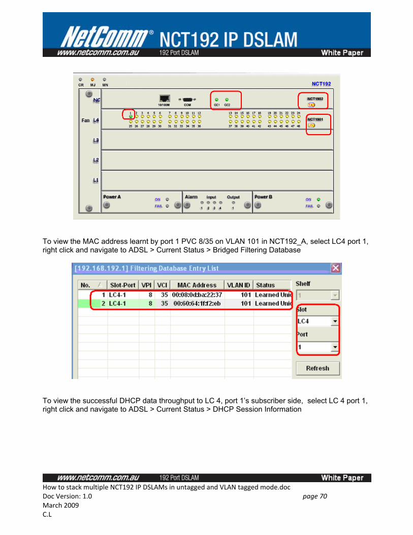
To view the MAC address learnt by port 1 PVC 8/35 on VLAN 101 in NCT192_A, select LC4 port 1, right click and navigate to ADSL > Current Status > Bridged Filtering Database
To view the successful DHCP data throughput to LC 4, port 1’s subscriber side, select LC 4 port 1, right click and navigate to ADSL > Current Status > DHCP Session Information
How to stack multiple NCT192 IP DSLAMs in untagged and VLAN tagged mode.docDoc Version: 1.0 page 70 March 2009C.L
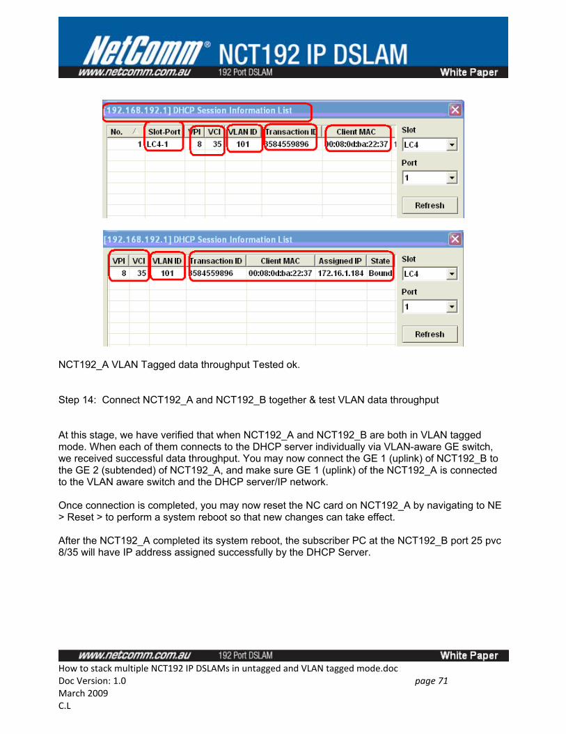
NCT192_A VLAN Tagged data throughput Tested ok.
Step 14: Connect NCT192_A and NCT192_B together & test VLAN data throughput
At this stage, we have verified that when NCT192_A and NCT192_B are both in VLAN tagged mode. When each of them connects to the DHCP server individually via VLAN-aware GE switch, we received successful data throughput. You may now connect the GE 1 (uplink) of NCT192_B to the GE 2 (subtended) of NCT192_A, and make sure GE 1 (uplink) of the NCT192_A is connected to the VLAN aware switch and the DHCP server/IP network.
Once connection is completed, you may now reset the NC card on NCT192_A by navigating to NE > Reset > to perform a system reboot so that new changes can take effect.
After the NCT192_A completed its system reboot, the subscriber PC at the NCT192_B port 25 pvc 8/35 will have IP address assigned successfully by the DHCP Server.
How to stack multiple NCT192 IP DSLAMs in untagged and VLAN tagged mode.docDoc Version: 1.0 page 71 March 2009C.L
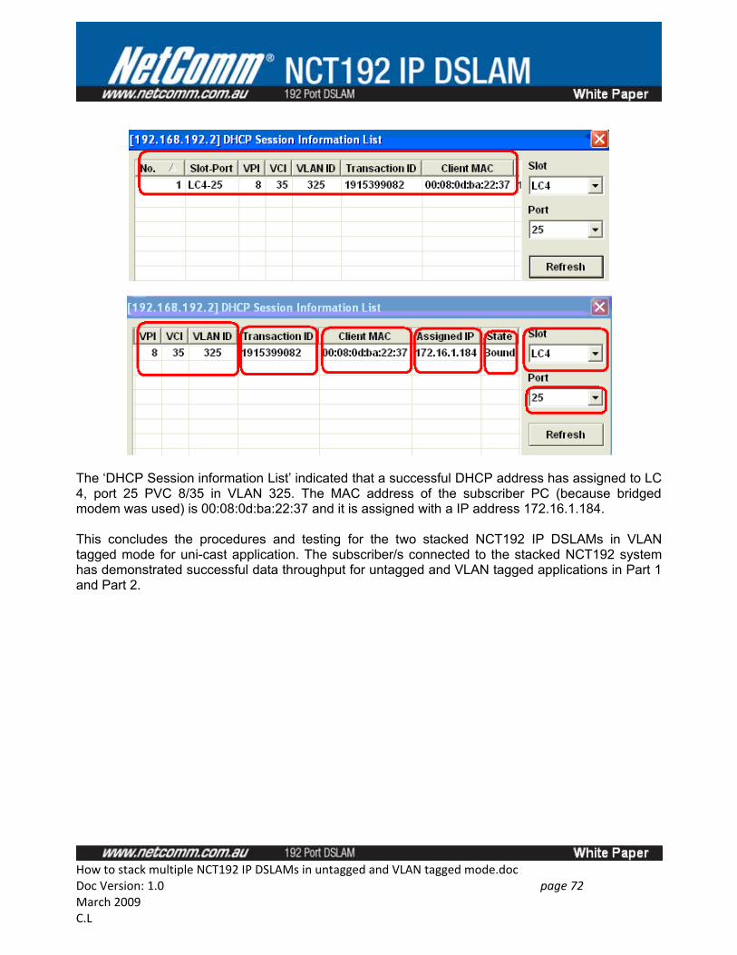
The ‘DHCP Session information List’ indicated that a successful DHCP address has assigned to LC 4, port 25 PVC 8/35 in VLAN 325. The MAC address of the subscriber PC (because bridged modem was used) is 00:08:0d:ba:22:37 and it is assigned with a IP address 172.16.1.184.
This concludes the procedures and testing for the two stacked NCT192 IP DSLAMs in VLAN tagged mode for uni-cast application. The subscriber/s connected to the stacked NCT192 system has demonstrated successful data throughput for untagged and VLAN tagged applications in Part 1 and Part 2.
How to stack multiple NCT192 IP DSLAMs in untagged and VLAN tagged mode.docDoc Version: 1.0 page 72 March 2009C.L