Embed Size (px)
Citation preview

Visit us online at www.groschopp.com
How to: Test & Evaluate Motors in Your Application
Table of Contents
1 INTRODUCTION ................................................................................... 1
2 UNDERSTANDING THE APPLICATION INPUT .................................. 1
2.1 Input Power ........................................................................................................................... 2
2.2 Load & Speed ........................................................................................................................ 3 2.2.1 Starting Torque ..................................................................................................................... 3
2.2.2 Peak Torque .......................................................................................................................... 3
2.2.3 Continuous Torque ................................................................................................................ 4
2.2.4 Intermittent Duty ................................................................................................................... 4
2.2.5 Speed ..................................................................................................................................... 6
2.3 Load Profile ........................................................................................................................... 6 2.3.1 Line Fed Motor ..................................................................................................................... 7
2.3.2 Open Loop System ................................................................................................................ 7
2.3.3 Closed Loop System (Speed Control) ................................................................................... 8
2.3.4 Closed Loop System (Torque Control) ................................................................................. 8
2.4 Packaging & Environment ................................................................................................... 8 2.4.1 Temperature .......................................................................................................................... 8
2.4.2 Ingress Protection .................................................................................................................. 9
2.4.3 Chemical Compatibility ...................................................................................................... 10
3 TESTING IN THE APPLICATION ....................................................... 10
3.1 Estimate the Application Loads ......................................................................................... 10
3.2 Determine the Actual Loads .............................................................................................. 10
3.3 Establish the Specification ................................................................................................. 11
3.4 Optimize the Design ............................................................................................................ 12
3.5 Finalize Testing ................................................................................................................... 12
4 SUMMARY .......................................................................................... 13
Groschopp, Inc. | How to: Test & Evaluate Motors in Your Application
Questions? Call (800) 829-4135 or Email [email protected] P a g e | 1
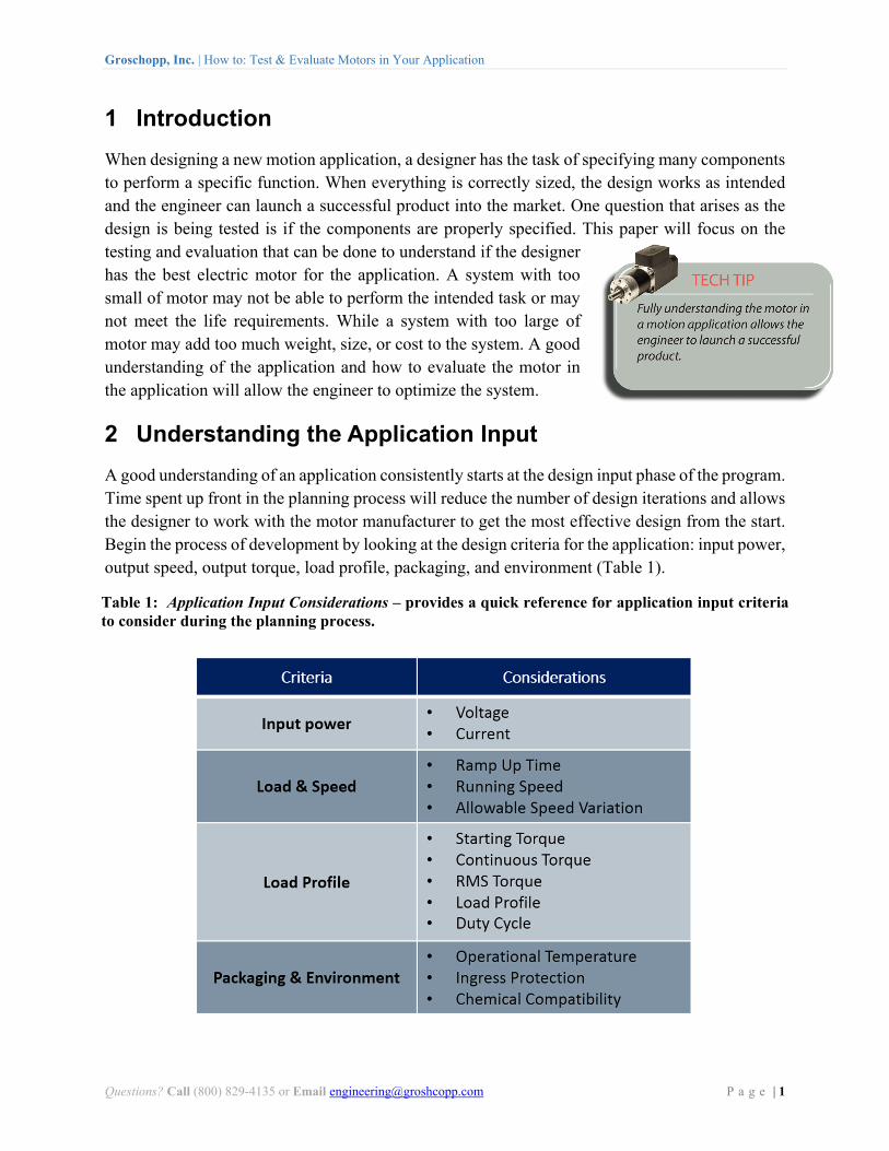
1 Introduction
When designing a new motion application, a designer has the task of specifying many components to perform a specific function. When everything is correctly sized, the design works as intended and the engineer can launch a successful product into the market. One question that arises as the design is being tested is if the components are properly specified. This paper will focus on the testing and evaluation that can be done to understand if the designer has the best electric motor for the application. A system with too small of motor may not be able to perform the intended task or may not meet the life requirements. While a system with too large of motor may add too much weight, size, or cost to the system. A good understanding of the application and how to evaluate the motor in the application will allow the engineer to optimize the system.
2 Understanding the Application Input
A good understanding of an application consistently starts at the design input phase of the program. Time spent up front in the planning process will reduce the number of design iterations and allows the designer to work with the motor manufacturer to get the most effective design from the start. Begin the process of development by looking at the design criteria for the application: input power, output speed, output torque, load profile, packaging, and environment (Table 1).
Table 1: Application Input Considerations – provides a quick reference for application input criteria to consider during the planning process.
Groschopp, Inc. | How to: Test & Evaluate Motors in Your Application
Questions? Call (800) 829-4135 or Email [email protected] P a g e | 2
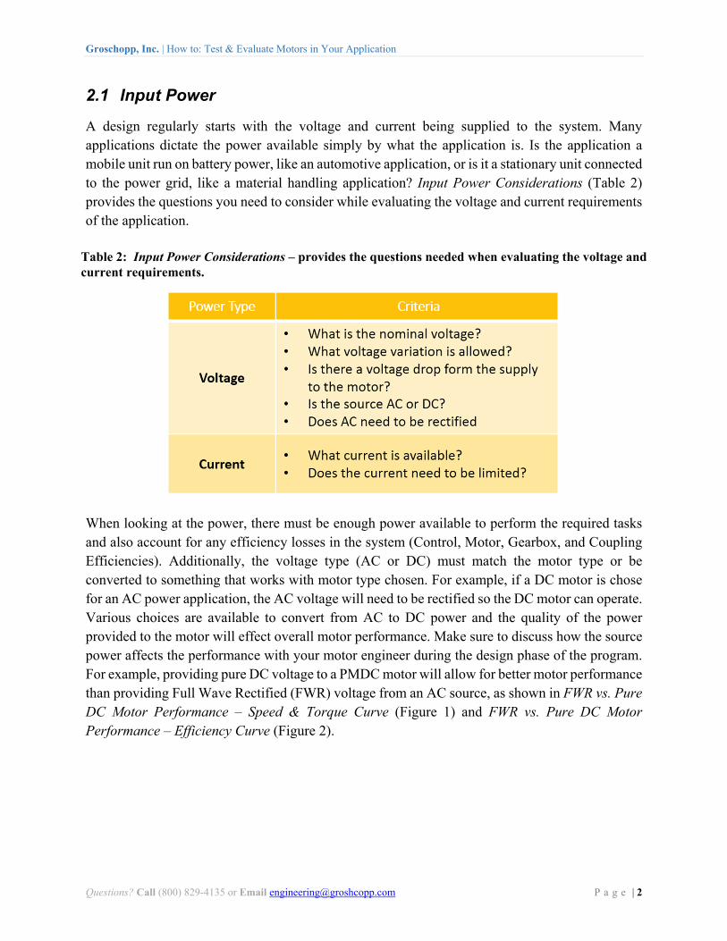
2.1 Input Power
A design regularly starts with the voltage and current being supplied to the system. Many applications dictate the power available simply by what the application is. Is the application a mobile unit run on battery power, like an automotive application, or is it a stationary unit connected to the power grid, like a material handling application? Input Power Considerations (Table 2) provides the questions you need to consider while evaluating the voltage and current requirements of the application.
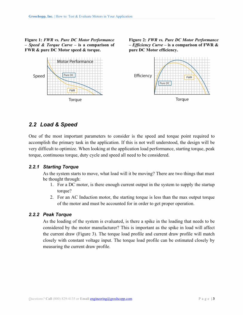
When looking at the power, there must be enough power available to perform the required tasks and also account for any efficiency losses in the system (Control, Motor, Gearbox, and Coupling Efficiencies). Additionally, the voltage type (AC or DC) must match the motor type or be converted to something that works with motor type chosen. For example, if a DC motor is chose for an AC power application, the AC voltage will need to be rectified so the DC motor can operate. Various choices are available to convert from AC to DC power and the quality of the power provided to the motor will effect overall motor performance. Make sure to discuss how the source power affects the performance with your motor engineer during the design phase of the program. For example, providing pure DC voltage to a PMDC motor will allow for better motor performance than providing Full Wave Rectified (FWR) voltage from an AC source, as shown in FWR vs. Pure DC Motor Performance – Speed & Torque Curve (Figure 1) and FWR vs. Pure DC Motor Performance – Efficiency Curve (Figure 2).
Table 2: Input Power Considerations – provides the questions needed when evaluating the voltage and current requirements.
Groschopp, Inc. | How to: Test & Evaluate Motors in Your Application
Questions? Call (800) 829-4135 or Email [email protected] P a g e | 3
2.2 Load & Speed
One of the most important parameters to consider is the speed and torque point required to accomplish the primary task in the application. If this is not well understood, the design will be very difficult to optimize. When looking at the application load performance, starting torque, peak torque, continuous torque, duty cycle and speed all need to be considered.
2.2.1 Starting Torque As the system starts to move, what load will it be moving? There are two things that must be thought through:
1. For a DC motor, is there enough current output in the system to supply the startup torque?
2. For an AC Induction motor, the starting torque is less than the max output torque of the motor and must be accounted for in order to get proper operation.
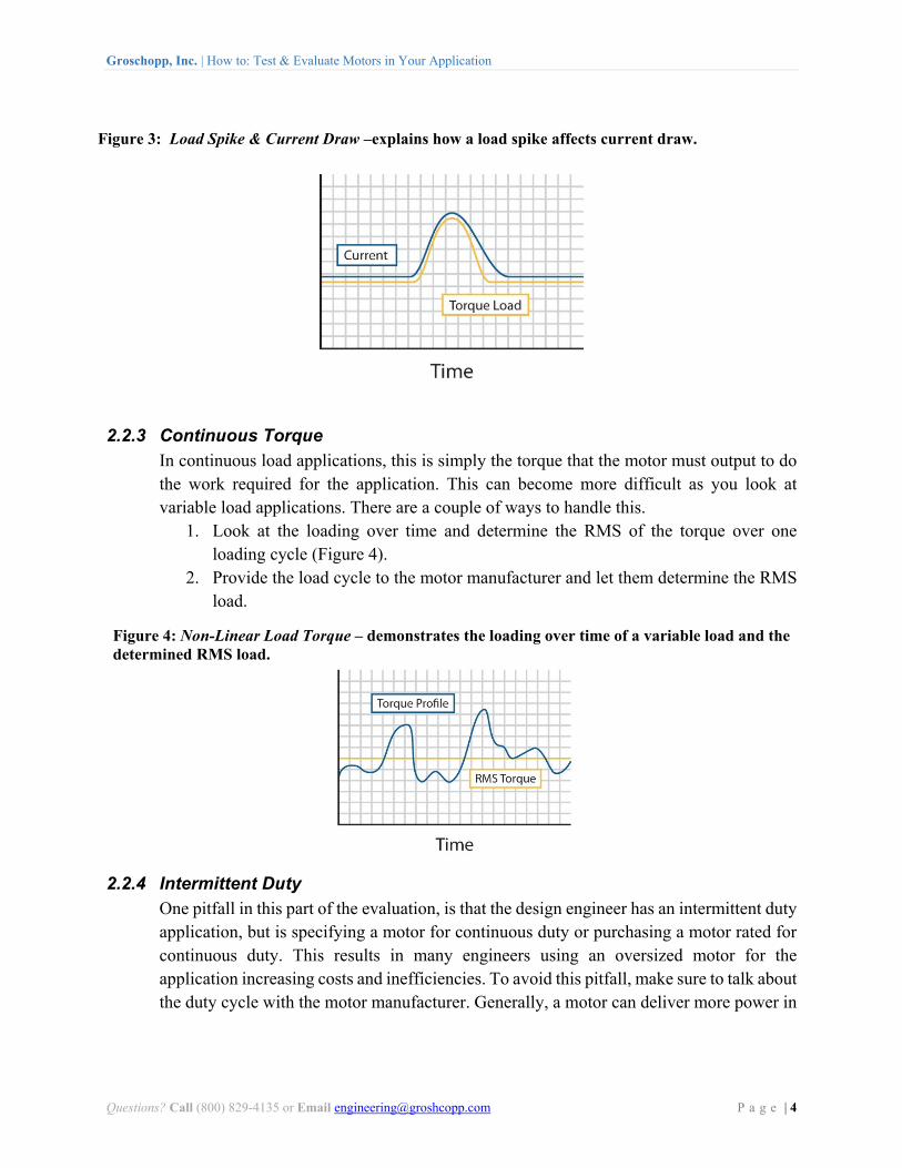
2.2.2 Peak Torque As the loading of the system is evaluated, is there a spike in the loading that needs to be considered by the motor manufacturer? This is important as the spike in load will affect the current draw (Figure 3). The torque load profile and current draw profile will match closely with constant voltage input. The torque load profile can be estimated closely by measuring the current draw profile.
Figure 1: FWR vs. Pure DC Motor Performance – Speed & Torque Curve – is a comparison of FWR & pure DC Motor speed & torque.
Figure 2: FWR vs. Pure DC Motor Performance – Efficiency Curve – is a comparison of FWR & pure DC Motor efficiency.
Groschopp, Inc. | How to: Test & Evaluate Motors in Your Application
Questions? Call (800) 829-4135 or Email [email protected] P a g e | 4
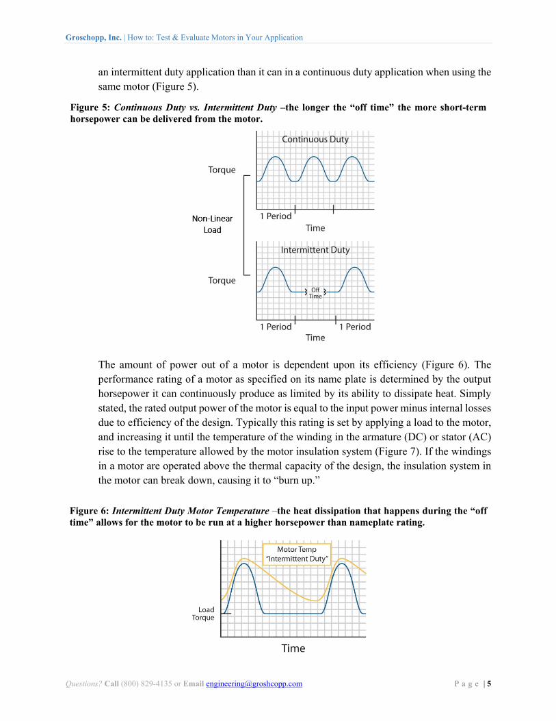
2.2.3 Continuous Torque In continuous load applications, this is simply the torque that the motor must output to do the work required for the application. This can become more difficult as you look at variable load applications. There are a couple of ways to handle this.
1. Look at the loading over time and determine the RMS of the torque over one loading cycle (Figure 4).
2. Provide the load cycle to the motor manufacturer and let them determine the RMS load.
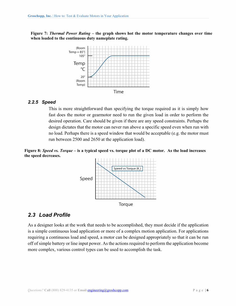
2.2.4 Intermittent Duty One pitfall in this part of the evaluation, is that the design engineer has an intermittent duty application, but is specifying a motor for continuous duty or purchasing a motor rated for continuous duty. This results in many engineers using an oversized motor for the application increasing costs and inefficiencies. To avoid this pitfall, make sure to talk about the duty cycle with the motor manufacturer. Generally, a motor can deliver more power in
Figure 3: Load Spike & Current Draw –explains how a load spike affects current draw.
Figure 4: Non-Linear Load Torque – demonstrates the loading over time of a variable load and the determined RMS load.
Groschopp, Inc. | How to: Test & Evaluate Motors in Your Application
Questions? Call (800) 829-4135 or Email [email protected] P a g e | 5
an intermittent duty application than it can in a continuous duty application when using the same motor (Figure 5).
The amount of power out of a motor is dependent upon its efficiency (Figure 6). The performance rating of a motor as specified on its name plate is determined by the output horsepower it can continuously produce as limited by its ability to dissipate heat. Simply stated, the rated output power of the motor is equal to the input power minus internal losses due to efficiency of the design. Typically this rating is set by applying a load to the motor, and increasing it until the temperature of the winding in the armature (DC) or stator (AC) rise to the temperature allowed by the motor insulation system (Figure 7). If the windings in a motor are operated above the thermal capacity of the design, the insulation system in the motor can break down, causing it to “burn up.”
Figure 5: Continuous Duty vs. Intermittent Duty –the longer the “off time” the more short-term horsepower can be delivered from the motor.
Figure 6: Intermittent Duty Motor Temperature –the heat dissipation that happens during the “off time” allows for the motor to be run at a higher horsepower than nameplate rating.
Groschopp, Inc. | How to: Test & Evaluate Motors in Your Application
Questions? Call (800) 829-4135 or Email [email protected] P a g e | 6
2.2.5 Speed This is more straightforward than specifying the torque required as it is simply how fast does the motor or gearmotor need to run the given load in order to perform the desired operation. Care should be given if there are any speed constraints. Perhaps the design dictates that the motor can never run above a specific speed even when run with no load. Perhaps there is a speed window that would be acceptable (e.g. the motor must run between 2500 and 2650 at the application load).
2.3 Load Profile
As a designer looks at the work that needs to be accomplished, they must decide if the application is a simple continuous load application or more of a complex motion application. For applications requiring a continuous load and speed, a motor can be designed appropriately so that it can be run off of simple battery or line input power. As the actions required to perform the application become more complex, various control types can be used to accomplish the task.
Figure 8: Speed vs. Torque – is a typical speed vs. torque plot of a DC motor. As the load increases the speed decreases.
Figure 7: Thermal Power Rating – the graph shows hot the motor temperature changes over time when loaded to the continuous duty nameplate rating.
Groschopp, Inc. | How to: Test & Evaluate Motors in Your Application
Questions? Call (800) 829-4135 or Email [email protected] P a g e | 7
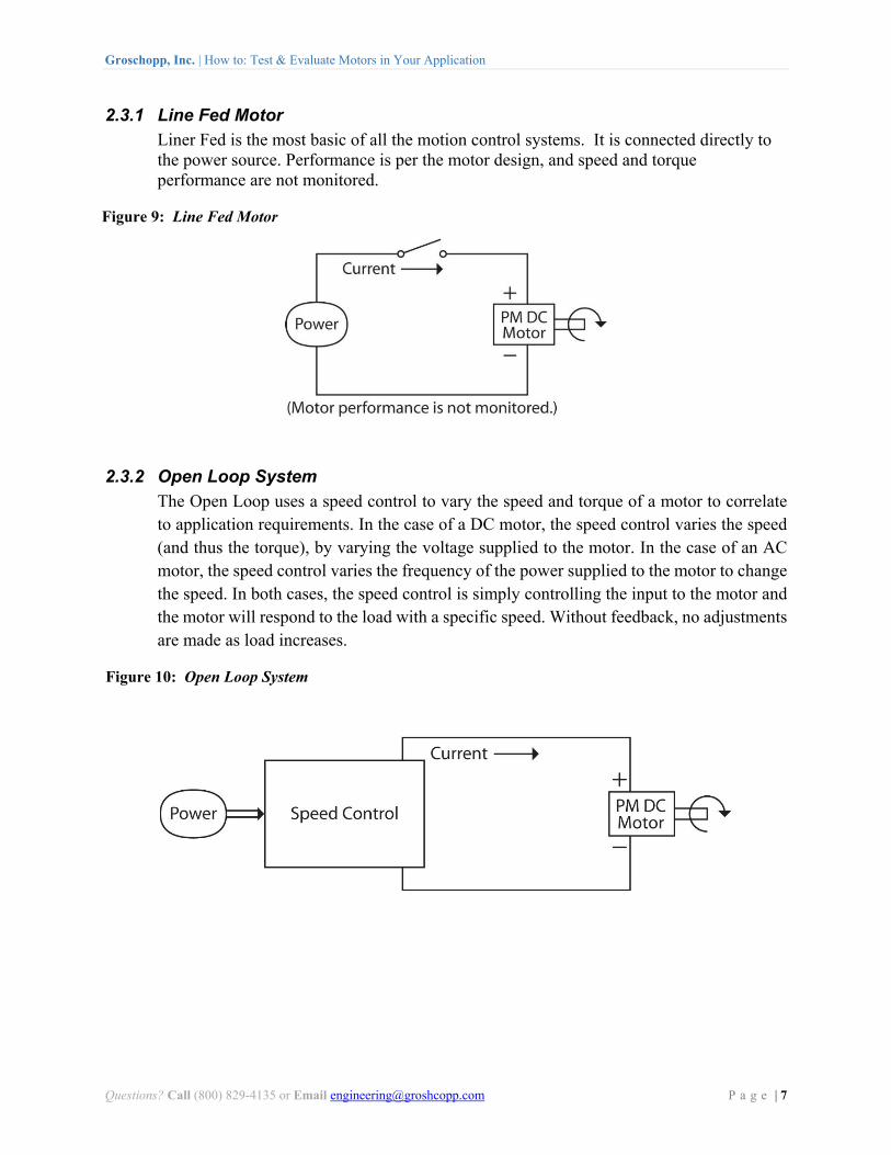
2.3.1 Line Fed Motor Liner Fed is the most basic of all the motion control systems. It is connected directly to the power source. Performance is per the motor design, and speed and torque performance are not monitored.
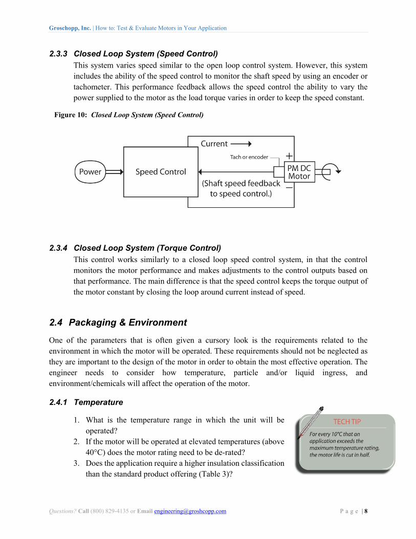
2.3.2 Open Loop System The Open Loop uses a speed control to vary the speed and torque of a motor to correlate to application requirements. In the case of a DC motor, the speed control varies the speed (and thus the torque), by varying the voltage supplied to the motor. In the case of an AC motor, the speed control varies the frequency of the power supplied to the motor to change the speed. In both cases, the speed control is simply controlling the input to the motor and the motor will respond to the load with a specific speed. Without feedback, no adjustments are made as load increases.
Figure 9: Line Fed Motor
Figure 10: Open Loop System
Groschopp, Inc. | How to: Test & Evaluate Motors in Your Application
Questions? Call (800) 829-4135 or Email [email protected] P a g e | 8
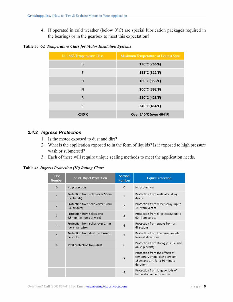
2.3.3 Closed Loop System (Speed Control) This system varies speed similar to the open loop control system. However, this system includes the ability of the speed control to monitor the shaft speed by using an encoder or tachometer. This performance feedback allows the speed control the ability to vary the power supplied to the motor as the load torque varies in order to keep the speed constant.
2.3.4 Closed Loop System (Torque Control) This control works similarly to a closed loop speed control system, in that the control monitors the motor performance and makes adjustments to the control outputs based on that performance. The main difference is that the speed control keeps the torque output of the motor constant by closing the loop around current instead of speed.
2.4 Packaging & Environment
One of the parameters that is often given a cursory look is the requirements related to the environment in which the motor will be operated. These requirements should not be neglected as they are important to the design of the motor in order to obtain the most effective operation. The engineer needs to consider how temperature, particle and/or liquid ingress, and environment/chemicals will affect the operation of the motor.
2.4.1 Temperature
1. What is the temperature range in which the unit will be operated?
2. If the motor will be operated at elevated temperatures (above 40°C) does the motor rating need to be de-rated?
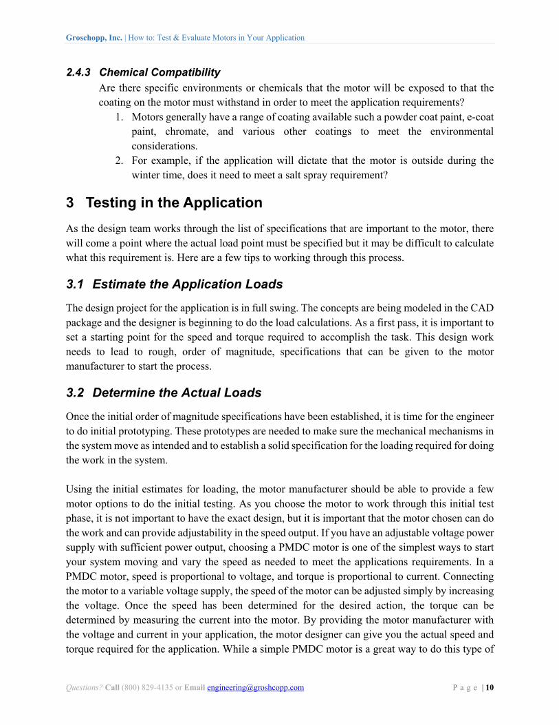
3. Does the application require a higher insulation classification than the standard product offering (Table 3)?
Figure 10: Closed Loop System (Speed Control)
Groschopp, Inc. | How to: Test & Evaluate Motors in Your Application
Questions? Call (800) 829-4135 or Email [email protected] P a g e | 9
4. If operated in cold weather (below 0°C) are special lubrication packages required in the bearings or in the gearbox to meet this expectation?
2.4.2 Ingress Protection 1. Is the motor exposed to dust and dirt? 2. What is the application exposed to in the form of liquids? Is it exposed to high pressure
wash or submersed? 3. Each of these will require unique sealing methods to meet the application needs.
Table 3: UL Temperature Class for Motor Insulation Systems
Table 4: Ingress Protection (IP) Rating Chart
Groschopp, Inc. | How to: Test & Evaluate Motors in Your Application
Questions? Call (800) 829-4135 or Email [email protected] P a g e | 10
2.4.3 Chemical Compatibility Are there specific environments or chemicals that the motor will be exposed to that the coating on the motor must withstand in order to meet the application requirements?
1. Motors generally have a range of coating available such a powder coat paint, e-coat paint, chromate, and various other coatings to meet the environmental considerations.
2. For example, if the application will dictate that the motor is outside during the winter time, does it need to meet a salt spray requirement?
3 Testing in the Application
As the design team works through the list of specifications that are important to the motor, there will come a point where the actual load point must be specified but it may be difficult to calculate what this requirement is. Here are a few tips to working through this process.
3.1 Estimate the Application Loads
The design project for the application is in full swing. The concepts are being modeled in the CAD package and the designer is beginning to do the load calculations. As a first pass, it is important to set a starting point for the speed and torque required to accomplish the task. This design work needs to lead to rough, order of magnitude, specifications that can be given to the motor manufacturer to start the process.
3.2 Determine the Actual Loads
Once the initial order of magnitude specifications have been established, it is time for the engineer to do initial prototyping. These prototypes are needed to make sure the mechanical mechanisms in the system move as intended and to establish a solid specification for the loading required for doing the work in the system. Using the initial estimates for loading, the motor manufacturer should be able to provide a few motor options to do the initial testing. As you choose the motor to work through this initial test phase, it is not important to have the exact design, but it is important that the motor chosen can do the work and can provide adjustability in the speed output. If you have an adjustable voltage power supply with sufficient power output, choosing a PMDC motor is one of the simplest ways to start your system moving and vary the speed as needed to meet the applications requirements. In a PMDC motor, speed is proportional to voltage, and torque is proportional to current. Connecting the motor to a variable voltage supply, the speed of the motor can be adjusted simply by increasing the voltage. Once the speed has been determined for the desired action, the torque can be determined by measuring the current into the motor. By providing the motor manufacturer with the voltage and current in your application, the motor designer can give you the actual speed and torque required for the application. While a simple PMDC motor is a great way to do this type of
Groschopp, Inc. | How to: Test & Evaluate Motors in Your Application
Questions? Call (800) 829-4135 or Email [email protected] P a g e | 11
testing, similar testing can be completed using a motor with a control. With a speed control, a PMDC, BLDC, or AC motor can be used.
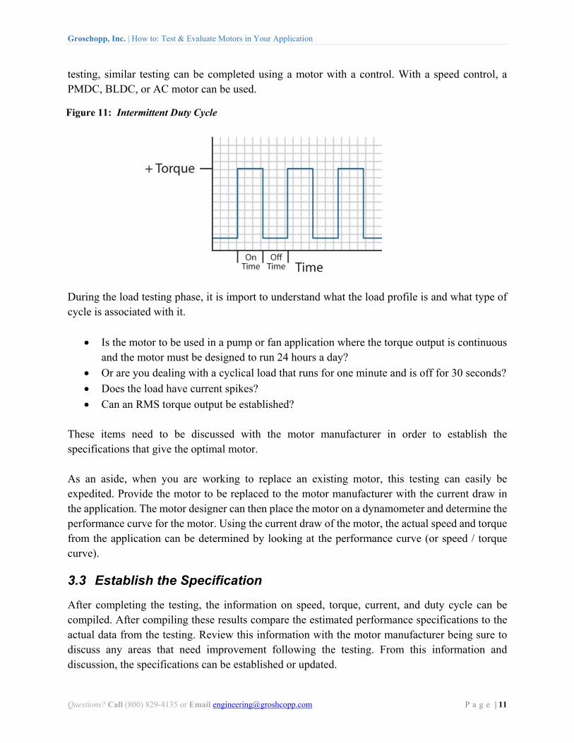
During the load testing phase, it is import to understand what the load profile is and what type of cycle is associated with it.
Is the motor to be used in a pump or fan application where the torque output is continuous and the motor must be designed to run 24 hours a day?
Or are you dealing with a cyclical load that runs for one minute and is off for 30 seconds?
Does the load have current spikes?
Can an RMS torque output be established?
These items need to be discussed with the motor manufacturer in order to establish the specifications that give the optimal motor.
As an aside, when you are working to replace an existing motor, this testing can easily be expedited. Provide the motor to be replaced to the motor manufacturer with the current draw in the application. The motor designer can then place the motor on a dynamometer and determine the performance curve for the motor. Using the current draw of the motor, the actual speed and torque from the application can be determined by looking at the performance curve (or speed / torque curve).
3.3 Establish the Specification
After completing the testing, the information on speed, torque, current, and duty cycle can be compiled. After compiling these results compare the estimated performance specifications to the actual data from the testing. Review this information with the motor manufacturer being sure to discuss any areas that need improvement following the testing. From this information and discussion, the specifications can be established or updated.
Figure 11: Intermittent Duty Cycle
Groschopp, Inc. | How to: Test & Evaluate Motors in Your Application
Questions? Call (800) 829-4135 or Email [email protected] P a g e | 12
3.4 Optimize the Design
A specification has been established and the team is ready to work on the final motor design in order to find the optimal match for the application. Usually by this time, a motor technology (AC Induction, Permanent Magnet DC, Brushless DC, or Universal) has already been chosen. If not, the motor designer should be able to help you weigh the pros and cons of each motor technology. Now it is time for the motor designer to dig into the archives of past designs and find a motor that provides the best fit for the design. Many times the designer will have to work on an optimized or a custom motor winding in order to provide the best fit performance. The motor designer is looking at the number of turns of wire to put in the winding and the length of the lamination stack in the motor winding. Do not be afraid of this customization. It typically does not add cost to your motor design, but may increase your lead times (in the prototyping stage). If a gear motor is under consideration, this is the point where the final gearbox type and ratio are chosen. After working to get the motor performance, the design effort turns to putting the parts into the best package to fit the application. This is where we look back at the design input and make the motor packaging to meet the environmental and sealing requirements of the application. Also, this would be a time to be looking at optimized mounting options for the application. Be sure to look for opportunities to eliminate components by using custom machining or custom casting to provide a smaller and more economical package.
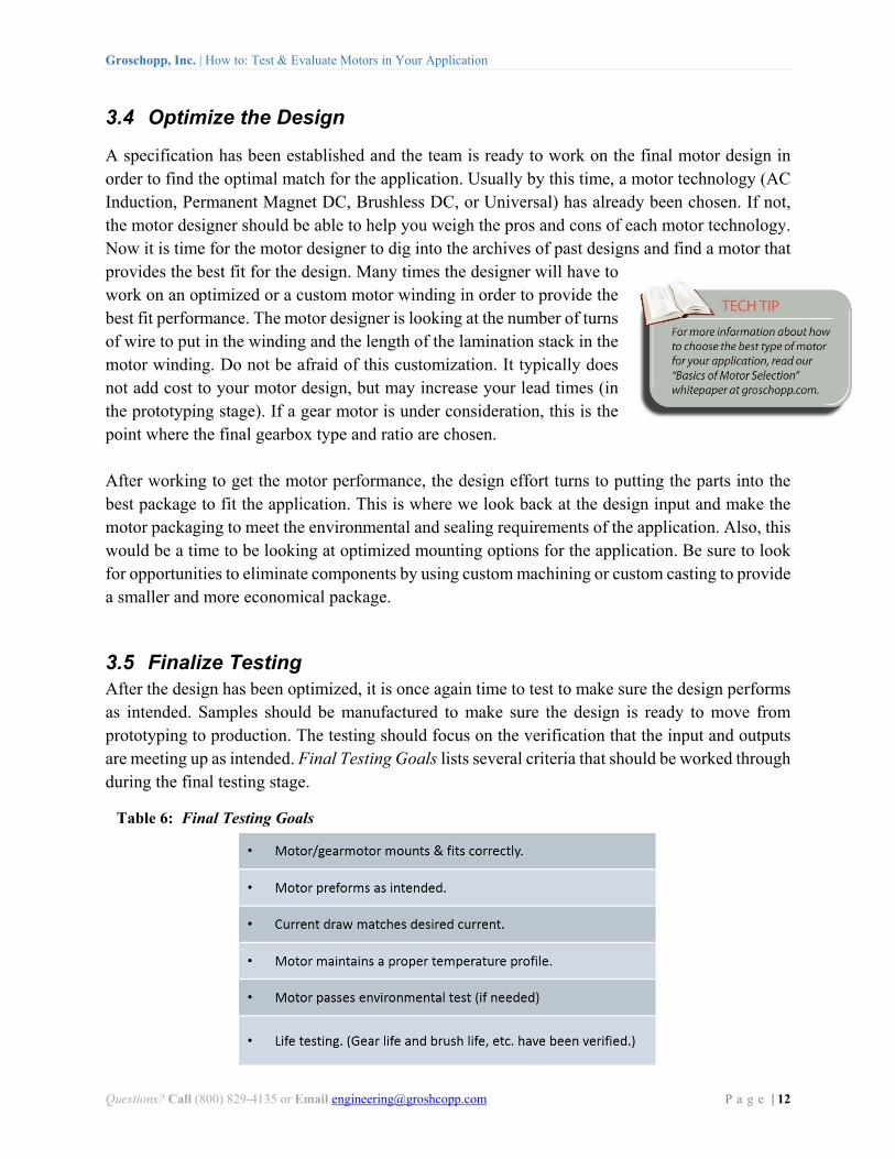
3.5 Finalize Testing After the design has been optimized, it is once again time to test to make sure the design performs as intended. Samples should be manufactured to make sure the design is ready to move from prototyping to production. The testing should focus on the verification that the input and outputs are meeting up as intended. Final Testing Goals lists several criteria that should be worked through during the final testing stage.
Table 6: Final Testing Goals

Groschopp, Inc. | How to: Test & Evaluate Motors in Your Application
Questions? Call (800) 829-4135 or Email [email protected] P a g e | 13
4 Summary
Testing and evaluating the motor in a motion application, whether it is a new application or a redesign of a current application, is an important part of the design process. Identifying the application input requirements allows the designer to work more effectively with the motor manufacturer to obtain the best motor for the application, allowing the engineer to choose the optimal design and have a successful product launch.