Embed Size (px)
Citation preview

HOWTOPROPERLY SET YOUR GAINSBY ERIC RUSSELL
You meticulously selected the right products for your car audio system, installed them, and finally connected them together. It sounds good, but are you getting the most out of your system? By properly adjusting your system gains, the Sound Quality (SQ) and/or Sound Pressure Level (SPL) can be greatly optimized.
NOTE: This is a complete version of our RFTECH “Gain Tutorial” (Knowledge Base ID #46). You can find instructions for building your own DIY “Distortion Meter” at Knowledge Base ID #1055 with a QR-Code link at the end of this article.
Dynamic RangeA car audio system can have its dynamic range greatly improved by simply adjusting system gains. By definition, “Dynamic Range” is the ratio of the loudest to faintest sounds reproduced without significant distortion, expressed in decibels (dB). Gain adjustments are typically found on amplifiers that control the sensitivity of the input circuit (signal processors use a level adjustment that controls the amplitude of the output circuit). A gain adjustment’s primary purpose is to match the output voltage of the source unit to the input circuit of the amplifier.
In a metaphor, let’s equate the gain control to the throttle adjustment on a carburetor, and the source unit’s volume knob to a gas pedal. Let’s also assume our hot-rod can produce up to 300 horsepower (HP). If our carburetor adjustment is increased, the engine will “idle” high and it will take minimal gas pedal travel to get the engine up to its 300 HP potential. Conversely, if our carburetor adjustment is decreased, the engine will “idle” low and it will take maximum gas pedal travel to get the engine up to its 300 HP potential. Where the carburetor is “set” doesn’t affect how much horsepower the engine can generate, just the effort needed to drive the engine to its full potential. Adjusting the throttle so our hot-rod idles at the proper RPM will – in effect – optimize the “dynamic range” of your gas pedal.
Source Unit VoltageSince a source unit is the starting point of our audio signal, it’s important to select a model that has a good preamplifier output, most importantly low “output impedance” and solid “output volt-age”. Many quality units provide 2 Volts or more at the RCA outputs. A common misconception is that source units always produce their rated output voltage as printed on their specification page. Say for example, if you have a 4V source unit – the myth is – the radio produces 4V all the time. Well, let’s take a closer look…
We tested a Panasonic CQ-RX400U rated at 2.0V RMS at the preamp outputs (RCA jacks). Fig 1 shows the radio’s maximum unclipped output (measured with a 1kHz @ 0dB test tone) was 2.1V RMS, so it exceeded its specification. After we determine the volume level needed to produce an unclipped signal, we’ll retain this position for the next two tests.
0
3
200m
400m
600m
800m
1
1.2
1.4
1.6
1.8
2
2.2
2.4
2.6
2.8
2.0982.098
V
0 555 10 15 20 25 30 35 40 45 5014.96 39.98
sec
dx=25.02 sec dy=-397.6 uV
Fig. 1

We then tested our “VOLUME – Under Pressure” CD Track #3 called “Let It Drop”. Fig 2 shows the average output was only 1.25V RMS with peaks up to 1.9V for the entire duration of the song. That’s 37.5% lower than its rated output!
We finally tested “KEANE – Hopes And Fears” CD Track #1 called “Somewhere Only We Know”. Fig 3 shows the average output was a mere 814mV RMS with peaks up to 1.674V. That’s over 59.3% lower than its rated output.
Now we know what happens when we play music (not test tones) in a car audio system. With the proper setup routine, we can help compensate for this anomaly by over driving the amplifier’s input stage by calculating the amount of “gain overlap” needed.
Gain Overlap If we want a “clean sounding” car audio system, it doesn’t mean setting the gain structure so our amplifier never clips. If we did, the absolute highest musical peak would occur at the threshold of clipping and there would be no audible distortion. In order to find a comfortable compromise between high signal-to-noise at low listening levels and low distortion at high listening levels, we need to understand “Gain Overlap”, which is the amount of input signal that overdrives the ampli-fier’s input measured in decibels. If using a signal processor, we want to optimize the dynamic range between the processor and amplifier, allowing the processor to determine the amount of gain overlap that drives the amplifier. Fig. 4 shows the characteristics associated with different levels of gain overlap & Fig. 5 shows the result as measured from the amplifier’s output terminals.
At first, you may be concerned with the amount of distortion (THD) the amplifier can produce, but the amplifier is only pro-ducing this during musical peaks, which account for a small percentage of the music track. Tests have shown that many people prefer +10 dB of gain overlap so the system retains reasonable Sound Quality while exhibiting an elevated Sound Pressure Level.
Gain Overlap Performance Amp Output THD0 dB Best signal-to-noise / Low SPL *0%
+5 dB Good signal-to-noise / Good SPL 20%+10 dB Best compromise between signal-to-noise and SPL 32%+15 dB Bad signal-to-noise / High SPL 39%+20 dB Terrible signal-to-noise / Best SPL 43%
*At 0dB there is no clipping distortion and therefore THD will fallback on the amplifier’s rated THD specification.$
Fig. 4
0
3
200m
400m
600m
800m
1
1.2
1.4
1.6
1.8
2
2.2
2.4
2.6
2.8
1.9
230.6m
V
0 16010 20 30 40 50 60 70 80 90 100 110 120 130 140 1508.504 103
sec
dx=94.53 sec dy=1.669 V
Fig. 2
0
3
200m
400m
600m
800m
1
1.2
1.4
1.6
1.8
2
2.2
2.4
2.6
2.8
1.674
126.1m
V
0 22020 40 60 80 100 120 140 160 180 200193.4140.7
sec
dx=-52.72 sec dy=-1.548 V
Fig. 3
Date/Time run: 02/14/12 * C:\PSPICE\CLIP THD.sch Temperature: 27.0
81:33:51 :emiT1 egaP2102 ,41 yraurbeF :etaD
(V) CLIP THD.dat (active)
Time
0s 0.5ms 1.0ms 1.5ms 2.0msv(5dB) v(10dB) v(15dB)v(0dB) v(20dB)
-15V
-10V
-5V
0V
5V
10V
15V
Fig. 5

Adjusting Gains by EarThis is the fastest and easiest method for adjusting system gains. The benefit is the cost which is FREE. It’s also fairly easy to do and only requires a screwdriver to adjust the gain controls.
Step 1. Adjust source unit Bass, Treble, and Balance to their center position. Step 2. Adjust all amplifier gains and any Punch EQ to minimum.
Without a Signal Processor Step 3. Play a music track with impactful bass, vocals and treble. Step 4. Increase the source unit volume to 3/4 (high performance source units to 7/8) maximum. Step 5. Increase the amplifier gain(s) until your preferred maximum loudness is achieved. If using ampli-fiers in bridged/mono mode or using two amplifiers in bd-SYNC mode, simultaneously increase both gain controls so they are balanced at the same level.
With a Signal Processor Step 3. Adjust all signal processor levels to minimum. Step 4. Play a music track with impactful bass, vocals and treble. Step 5. Increase the source unit volume to 3/4 (high performance source units to 7/8) maximum. Step 6. Increase the signal processor level output until your preferred maximum loudness is achieved. If the maximum processor output level is reached and system still does not play loud enough, then slowly in-crease the amplifier gain controls until your preferred maximum loudness is achieved. If using amplifiers in bridged/mono mode or using two amplifiers in bd-SYNC mode, simultaneously increase both gain controls so they are balanced at the same level.

Adjusting Gains by MeterThis is the most cost effective method for adjusting system gains with predictable accuracy. This procedure references a DIY Distortion Meter as follows; 1) Mini-Amplified Speaker, 2) Source Unit Voltage Divider, and 3) Amplifier Voltage Divid-er. A link for building your own DIY Distortion Meter is at the end of this article.
Step 1. Disconnect all speakers and RCA cables from source unit. Adjust Bass, Treble, and Balance to their center position. Step 2. Connect the RCA end of the “Source Unit Voltage Divider” to the source unit’s RCA output. Con-nect the 1/8” jack end to the “Mini Amplified Speaker”. Step 3. Play a test tone, 1kHz @ 0dB. If source unit has a REPEAT TRACK function, press this button to provide adequate time to perform Step 4. Step 4. Turn on the “Mini Amplified Speaker” to a low listening level. Increase the source unit’s volume un-til the maximum output is produced without clipping (at clipping you can hear the tone change from clean to raspy). Stop the track when the test is complete. DO NOT change the source unit’s volume position.
Without a Signal Processor Step 5. Reconnect RCAs between source unit and amplifier(s). Step 6. Disconnect all speakers from amplifier(s). Adjust all amplifier gains and any Punch EQ to minimum. Step 7. Connect the alligator clips from the “Amplifier Voltage Divider” to the amplifier’s speaker outputs. Connect the 1/8” jack end to the “Mini Amplified Speaker”. Step 8. Play the test tone of your choice (0dB/-5dB/-10dB) for the desired gain overlap. Step 9. Increase amplifier gain(s) until maximum amplifier output is produced without clipping (again, listen for the tone to change from clean to raspy). If using amplifiers in bridged/mono mode or using two amplifi-ers in bd-SYNC mode, simultaneously increase both gain controls so they are balanced (at the same level).
With a Signal Processor Step 5. Reconnect RCAs between source unit and signal processor(s). Step 6. Disconnect all speakers from amplifier(s). Adjust all amplifier gains and any Punch EQ to minimum. Step 7.) Connect the alligator clips from the “Amplifier Voltage Divider” to the amplifier’s speaker outputs. Connect the 1/8” jack end to the “Mini Amplified Speaker”. Step 8. Play the test tone of your choice (0dB/-5dB/-10dB) for the desired gain overlap. Step 9. Increase signal processor gain(s) until maximum amplifier output is produced without clipping (again, listen for the tone to change from clean to raspy). If the maximum processor output level is reached and system still does not play loud enough, then slowly increase the amplifier gain controls until amplifier reaches the threshold of clipping. If using amplifiers in bridged/mono mode or using two amplifiers in bd-SYNC mode, simultaneously increase both gain controls so they are balanced (at the same level).

Adjusting Gains by OscilloscopeThis is the most accurate method for adjusting system gains. However, the ex-pense of owning an oscilloscope or access to one makes this option out of reach for most people. Fanatics entering Sound Quality competitions should use this.
Step 1. Disconnect all speakers and RCA cables from source unit. Adjust Bass, Treble, and Balance to their center position. Step 2. Connect the oscilloscope to the source unit’s RCA output. Step 3. Play a test tone, 1kHz @ 0dB. If source unit has a REPEAT TRACK function, press this button to provide adequate time to perform Step 4. Step 4. Increase the source unit’s volume until maximum output is produced without clipping. Stop the track when the test is complete. DO NOT change the source unit’s volume position. Without a Signal Processor Step 5. Reconnect RCAs between source unit and amplifier(s). Step 6. Disconnect all speakers from amplifier(s). Adjust all amplifier gains and any Punch EQ to minimum. Step 7. Connect the oscilloscope to the amplifier’s speaker outputs. Step 8. Play the test tone of your choice (0dB/-5dB/-10dB) for the desired gain overlap. Step 9. Increase amplifier gain(s) until maximum output is produced without clipping. If using amplifiers in bridged/mono mode or using two amplifiers in bd-SYNC mode, simultaneously increase both gain controls so they are balanced (at the same level). With a Signal Processor Step 5. Reconnect RCAs between source unit and signal processor(s). Adjust all signal processor gains to minimum. Step 6. Disconnect all speakers from amplifier(s). Adjust all amplifier gains and any Punch EQ to minimum. Step 7. Connect the oscilloscope to the amplifier’s speaker outputs. Step 8. Play the test tone of your choice (0dB/-5dB/-10dB) for the desired gain overlap. Step 9. Increase the signal processor gain(s) until maximum output is produced from amplifier without clip-ping. If the maximum processor output level is reached and amplifier(s) still do not clip, then slowly in-crease the amplifier gain controls until the amplifier reaches the threshold of clipping. If using amplifiers in bridged/mono mode or using two amplifiers in bd-SYNC mode, simultaneously increase both gain controls so they are balanced (at the same level).
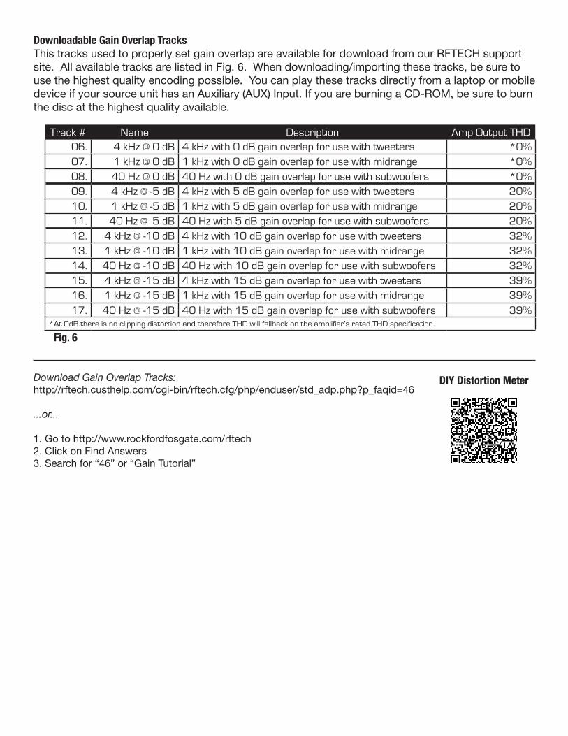
Track # Name Description Amp Output THD06. 4 kHz @ 0 dB 4 kHz with 0 dB gain overlap for use with tweeters *0%07. 1 kHz @ 0 dB 1 kHz with 0 dB gain overlap for use with midrange *0%08. 40 Hz @ 0 dB 40 Hz with 0 dB gain overlap for use with subwoofers *0%09. 4 kHz @ -5 dB 4 kHz with 5 dB gain overlap for use with tweeters 20%10. 1 kHz @ -5 dB 1 kHz with 5 dB gain overlap for use with midrange 20%11. 40 Hz @ -5 dB 40 Hz with 5 dB gain overlap for use with subwoofers 20%12. 4 kHz @ -10 dB 4 kHz with 10 dB gain overlap for use with tweeters 32%13. 1 kHz @ -10 dB 1 kHz with 10 dB gain overlap for use with midrange 32%14. 40 Hz @ -10 dB 40 Hz with 10 dB gain overlap for use with subwoofers 32%15. 4 kHz @ -15 dB 4 kHz with 15 dB gain overlap for use with tweeters 39%16. 1 kHz @ -15 dB 1 kHz with 15 dB gain overlap for use with midrange 39%17. 40 Hz @ -15 dB 40 Hz with 15 dB gain overlap for use with subwoofers 39%
*At 0dB there is no clipping distortion and therefore THD will fallback on the amplifier’s rated THD specification.$
Fig. 6
DIY Distortion Meter
Downloadable Gain Overlap Tracks This tracks used to properly set gain overlap are available for download from our RFTECH support site. All available tracks are listed in Fig. 6. When downloading/importing these tracks, be sure to use the highest quality encoding possible. You can play these tracks directly from a laptop or mobile device if your source unit has an Auxiliary (AUX) Input. If you are burning a CD-ROM, be sure to burn the disc at the highest quality available.
Download Gain Overlap Tracks:http://rftech.custhelp.com/cgi-bin/rftech.cfg/php/enduser/std_adp.php?p_faqid=46
...or...
1. Go to http://www.rockfordfosgate.com/rftech2. Click on Find Answers3. Search for “46” or “Gain Tutorial”

DIY Distortion Meter The “Better” and “Best” sections of the “Properly Set Your Gains” article references a DIY “Distortion Meter”.
You can learn how to build this Do-It-Yourself Distortion Meter for under $30! We’ll supply the schematics for building a “Source Unit Voltage Divider” and “Amplifier Voltage Divider” using parts available from your local RadioShack® store.
Download DIY Distortion Meter Instructions:http://rftech.custhelp.com/cgi-bin/rftech.cfg/php/enduser/std_adp.php?p_faqid=1055
...or...
1. Go to http://www.rockfordfosgate.com/rftech2. Click on Find Answers3. Search for “DIY Distortion Meter
Gain Overlap Tracks
RadioShack® is a registered trademark of RadioSheck Corporation.

E.W.R. V1.1 05/18/2012
©2012 Rockford Corporation, All Rights Reserved
Notes