Embed Size (px)
Citation preview
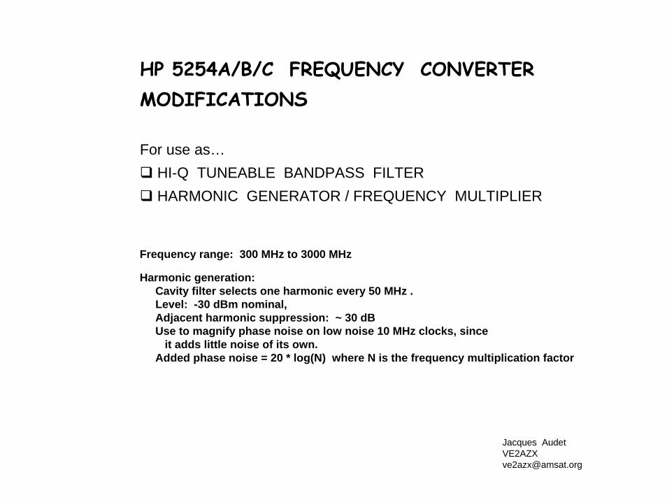
HP 5254A/B/C FREQUENCY CONVERTER MODIFICATIONS
For use as… HI-Q TUNEABLE BANDPASS FILTERHARMONIC GENERATOR / FREQUENCY MULTIPLIER
Frequency range: 300 MHz to 3000 MHz
Harmonic generation: Cavity filter selects one harmonic every 50 MHz .Level: -30 dBm nominal, Adjacent harmonic suppression: ~ 30 dBUse to magnify phase noise on low noise 10 MHz clocks, since
it adds little noise of its own.Added phase noise = 20 * log(N) where N is the frequency multiplication factor
Jacques [email protected]
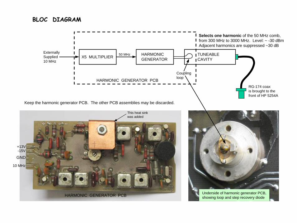
BLOC DIAGRAM
X5 MULTIPLIER HARMONICGENERATOR
TUNEABLECAVITY
Couplingloop
50 MHzExternallySupplied10 MHz
Selects one harmonic of the 50 MHz comb,from 300 MHz to 3000 MHz. Level: ~ -30 dBmAdjacent harmonics are suppressed ~30 dB
HARMONIC GENERATOR PCBRG-174 coaxis brought to thefront of HP 5254A
HARMONIC GENERATOR PCB
GND
+13V-15V
10 MHz
Keep the harmonic generator PCB. The other PCB assemblies may be discarded.
This heat sinkwas added
Underside of harmonic generator PCB,showing loop and step recovery diode
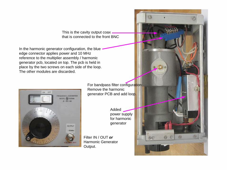
This is the cavity output coaxthat is connected to the front BNC
In the harmonic generator configuration, the blue edge connector applies power and 10 MHz reference to the multiplier assembly / harmonicgenerator pcb, located on top. The pcb is held in place by the two screws on each side of the loop.The other modules are discarded.
Filter IN / OUT orHarmonic GeneratorOutput.
For bandpass filter configuration:Remove the harmonic generator PCB and add loop.
Addedpower supplyfor harmonicgenerator
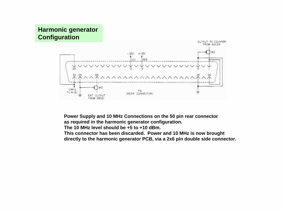
Harmonic generator Configuration
Power Supply and 10 MHz Connections on the 50 pin rear connectoras required in the harmonic generator configuration.The 10 MHz level should be +5 to +10 dBm.This connector has been discarded. Power and 10 MHz is now brought directly to the harmonic generator PCB, via a 2x6 pin double side connector.
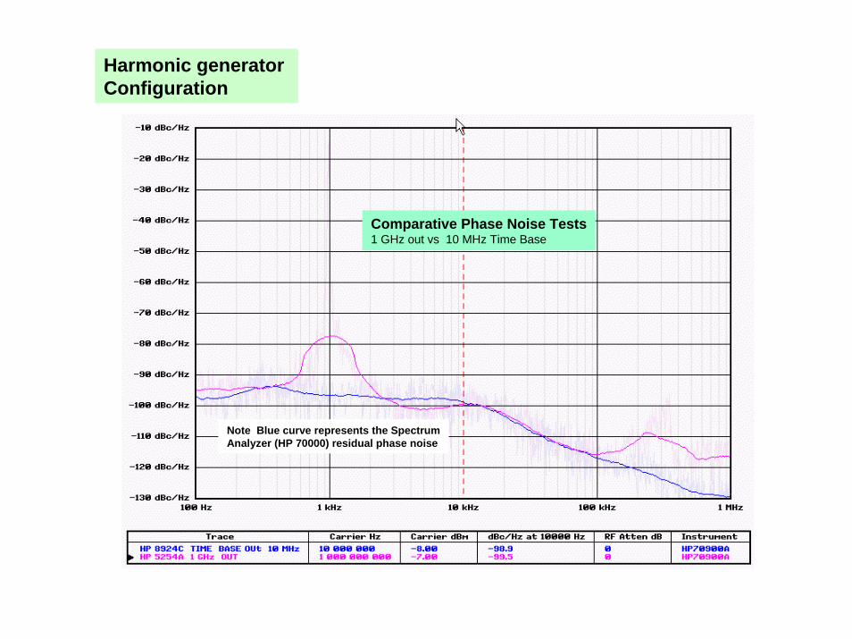
Harmonic generator Configuration
Comparative Phase Noise Tests1 GHz out vs 10 MHz Time Base
Note Blue curve represents the SpectrumAnalyzer (HP 70000) residual phase noise
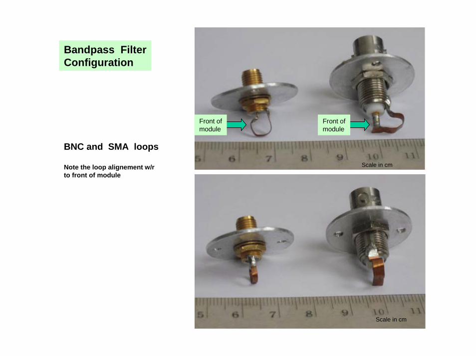
Front ofmodule
Front ofmodule
Bandpass FilterConfiguration
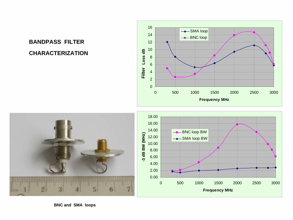
BNC and SMA loops
Note the loop alignement w/rto front of module
Scale in cm
Scale in cm
0
2
4
6
8
10
12
14
16
0 500 1000 1500 2000 2500 3000
Frequency MHz
Loss
dB
SMA loopBNC loop
Filte
r
BANDPASS FILTER
CHARACTERIZATION
0.00
2.00
4.00
6.00
8.0010.00
12.00
14.00
16.00
18.00
0 500 1000 1500 2000 2500 3000
Frequency MHz
-3 d
B B
W (M
Hz) BNC loop BW
SMA loop BW
BNC and SMA loops
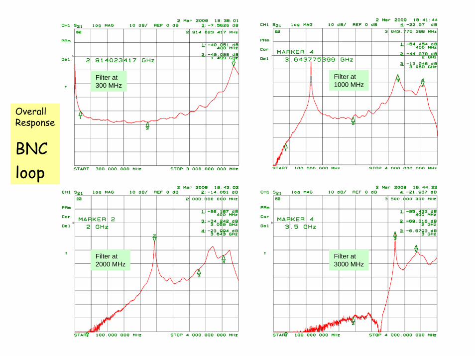
Filter at 1000 MHz
OverallResponse
BNCloop
Filter at 300 MHz
Filter at 2000 MHz
Filter at 3000 MHz
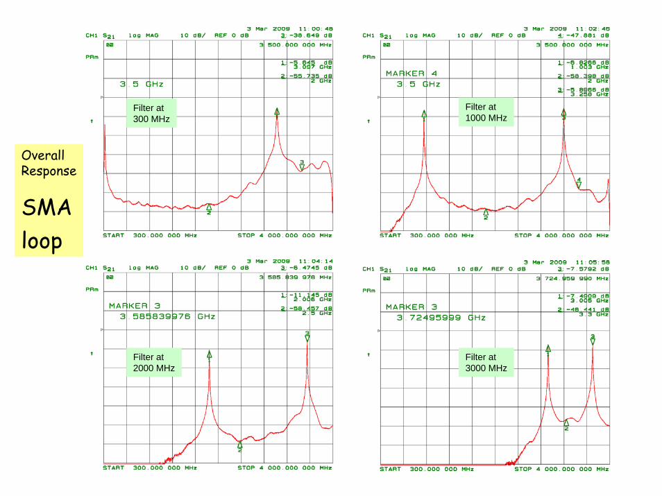
OverallResponse
SMAloop
Filter at 1000 MHz
Filter at 300 MHz
Filter at 2000 MHz
Filter at 3000 MHz
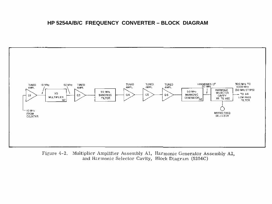
HP 5254A/B/C FREQUENCY CONVERTER – BLOCK DIAGRAM
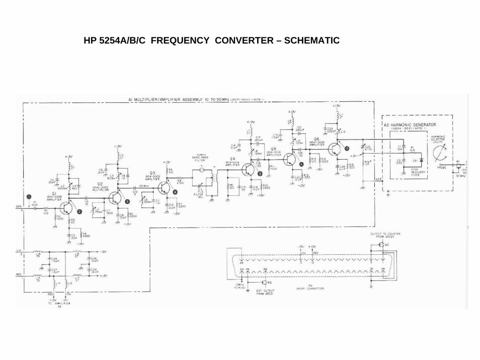
HP 5254A/B/C FREQUENCY CONVERTER – SCHEMATIC
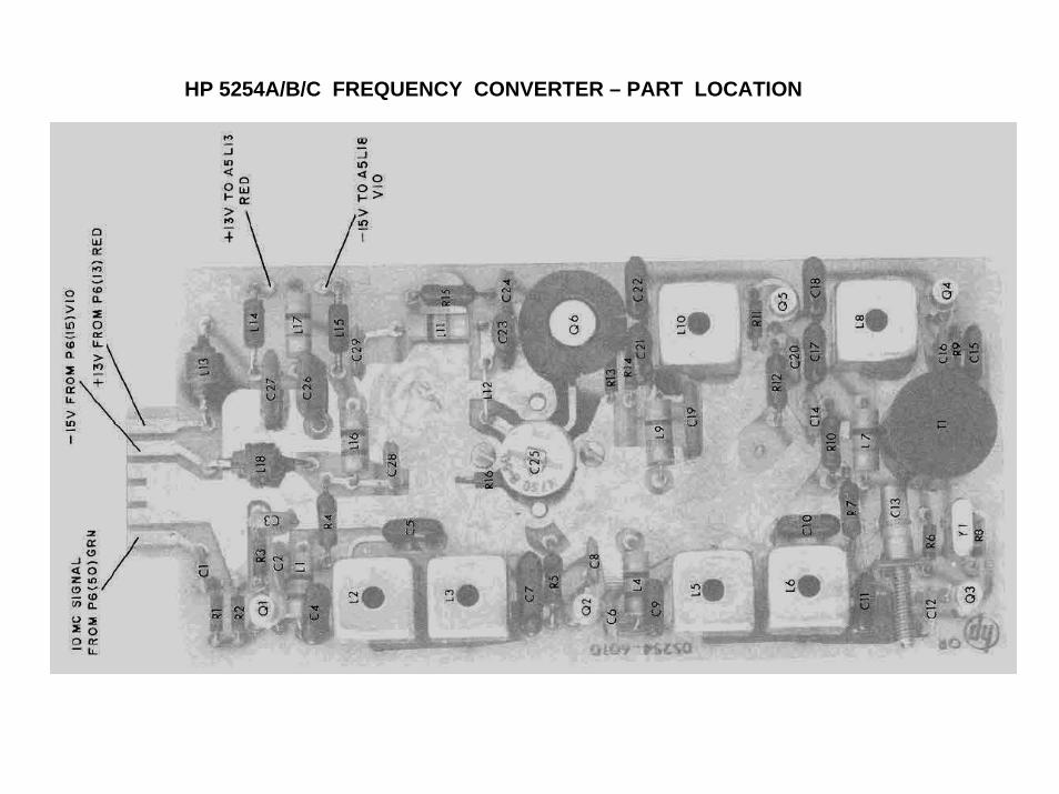
HP 5254A/B/C FREQUENCY CONVERTER – PART LOCATION