Embed Size (px)
Citation preview
HP CONFIDENTIAL Writer: SCaesar File Name: a-frnt.doc
Codename: Northstar Part Number: 335900-002 Last Saved On: 10/2/03 3:33 PM
HP StorageWorks Modular Smart Array 30
User Guide (Formerly HP StorageWorks
Model 4400 Family of Ultra320 SCSI Disk Enclosures)
November 2003 (Second Edition) Part Number 335900-002

HP CONFIDENTIAL Writer: SCaesar File Name: a-frnt.doc
Codename: Northstar Part Number: 335900-002 Last Saved On: 10/2/03 3:33 PM
© 2003 Hewlett-Packard Development Company, L.P.
The information contained herein is subject to change without notice. The only warranties for HP products and services are set forth in the express warranty statements accompanying such products and services. Nothing herein should be construed as constituting an additional warranty. HP shall not be liable for technical or editorial errors or omissions contained herein.
HP StorageWorks Modular Smart Array 30 User Guide
November 2003 (Second Edition) Part Number 335900-002
HP StorageWorks Modular Smart Array 30 User Guide iii
HP CONFIDENTIAL Writer: SCaesar File Name: a-frnt.doc
Codename: Northstar Part Number: 335900-002 Last Saved On: 10/2/03 3:33 PM
Contents
About This Guide Audience Assumptions..................................................................................................... vii Important Safety Information ........................................................................................... vii Symbols on Equipment .................................................................................................... vii Rack Stability .................................................................................................................... ix Symbols in Text................................................................................................................. ix Getting Help ........................................................................................................................x
Technical Support .........................................................................................................x HP Website ...................................................................................................................x Authorized Reseller .................................................................................................... xi
Reader’s Comments .......................................................................................................... xi
Chapter 1 System and Components System ............................................................................................................................. 1-1 Ultra320 I/O Module ....................................................................................................... 1-3 Environmental Monitoring Unit ...................................................................................... 1-4 Disk Drive and Drive Blank ............................................................................................ 1-6 Power Supply and Blower Assembly .............................................................................. 1-7
Chapter 2 Installing the System in a Rack Removing the System Components................................................................................. 2-1
Drive Blanks ............................................................................................................. 2-1 Disk Drives ............................................................................................................... 2-1 Power Supply Assembly ........................................................................................... 2-2 EMU.......................................................................................................................... 2-2
Contents
iv HP StorageWorks Modular Smart Array 30 User Guide
HP CONFIDENTIAL Writer: SCaesar File Name: a-frnt.doc
Codename: Northstar Part Number: 335900-002 Last Saved On: 10/2/03 3:33 PM
I/O Module ................................................................................................................2-2 Mounting the System in a Rack .......................................................................................2-2 Completing the Installation..............................................................................................2-7 Verifying Normal Operation............................................................................................2-8
System LEDs.............................................................................................................2-8 Power Supply Assembly LED...................................................................................2-8 I/O Module LEDs......................................................................................................2-9 EMU LED ...............................................................................................................2-10 Disk Drive LEDs.....................................................................................................2-11
Chapter 3 Replacing System Components Replacement Procedures..................................................................................................3-2
Disk Drive or Drive Blank ........................................................................................3-2 Blower .......................................................................................................................3-4 Power Supply Unit ....................................................................................................3-5 EMU..........................................................................................................................3-6 I/O Module ................................................................................................................3-7
Appendix A Regulatory Compliance Notices Federal Communications Commission Notice ...............................................................A-1
Class A Equipment...................................................................................................A-2 Class B Equipment ...................................................................................................A-2 Declaration of Conformity for Products Marked with the FCC Logo, United States Only..........................................................................................................................A-3 Modifications ...........................................................................................................A-3 Cables .......................................................................................................................A-3
Canadian Notice (Avis Canadien) ..................................................................................A-4 Class A Equipment...................................................................................................A-4 Class B Equipment ...................................................................................................A-4
European Union Notice ..................................................................................................A-4 Japanese Notice...............................................................................................................A-5 Korean Notice .................................................................................................................A-6
Class A Equipment...................................................................................................A-6 Class B Equipment ...................................................................................................A-6
BSMI Notice ...................................................................................................................A-6

Contents
HP StorageWorks Modular Smart Array 30 User Guide v
HP CONFIDENTIAL Writer: SCaesar File Name: a-frnt.doc
Codename: Northstar Part Number: 335900-002 Last Saved On: 10/2/03 3:33 PM
Appendix B Electrostatic Discharge Preventing Electrostatic Damage ....................................................................................B-1 Grounding Methods to Prevent Electrostatic Damage ....................................................B-2
Appendix C Specifications Power Specifications .......................................................................................................C-1 Environmental Specifications..........................................................................................C-2 Physical Specifications....................................................................................................C-2
Appendix D SCSI Address Map
Index

HP StorageWorks Modular Smart Array 30 User Guide vii
HP CONFIDENTIAL Writer: SCaesar File Name: a-frnt.doc
Codename: Northstar Part Number: 335900-002 Last Saved On: 10/2/03 3:33 PM
About This Guide
This guide provides step-by-step installation instructions and reference information for operation and troubleshooting for the HP StorageWorks Modular Smart Array 30.
Audience Assumptions
This guide is for the person who installs, administers, and troubleshoots servers. HP assumes you are qualified in the servicing of computer equipment and trained in recognizing hazards in products with hazardous energy levels.
Important Safety Information
Before installing this product, read the Important Safety Information document included with the system.
Symbols on Equipment
The following symbols may be placed on equipment to indicate the presence of potentially hazardous conditions:
WARNING: This symbol, in conjunction with any of the following symbols, indicates the presence of a potential hazard. The potential for injury exists if warnings are not observed. Consult your documentation for specific details.
About This Guide
viii HP StorageWorks Modular Smart Array 30 User Guide
HP CONFIDENTIAL Writer: SCaesar File Name: a-frnt.doc
Codename: Northstar Part Number: 335900-002 Last Saved On: 10/2/03 3:33 PM
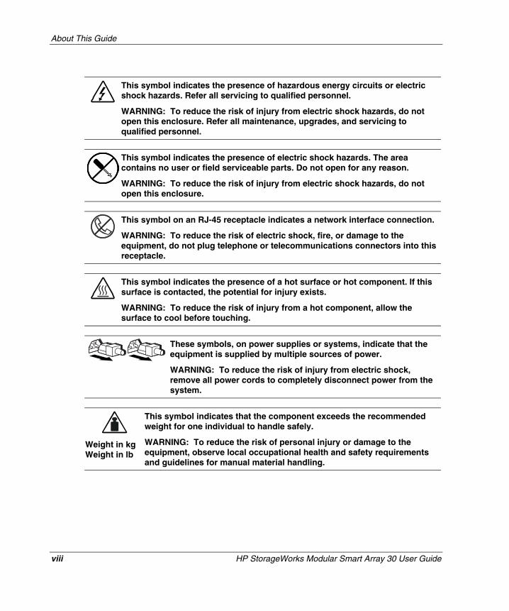
This symbol indicates the presence of hazardous energy circuits or electric shock hazards. Refer all servicing to qualified personnel.
WARNING: To reduce the risk of injury from electric shock hazards, do not open this enclosure. Refer all maintenance, upgrades, and servicing to qualified personnel.
This symbol indicates the presence of electric shock hazards. The area contains no user or field serviceable parts. Do not open for any reason.
WARNING: To reduce the risk of injury from electric shock hazards, do not open this enclosure.
This symbol on an RJ-45 receptacle indicates a network interface connection.
WARNING: To reduce the risk of electric shock, fire, or damage to the equipment, do not plug telephone or telecommunications connectors into this receptacle.
This symbol indicates the presence of a hot surface or hot component. If this surface is contacted, the potential for injury exists.
WARNING: To reduce the risk of injury from a hot component, allow the surface to cool before touching.
These symbols, on power supplies or systems, indicate that the equipment is supplied by multiple sources of power.
WARNING: To reduce the risk of injury from electric shock, remove all power cords to completely disconnect power from the system.
Weight in kg Weight in lb
This symbol indicates that the component exceeds the recommended weight for one individual to handle safely.
WARNING: To reduce the risk of personal injury or damage to the equipment, observe local occupational health and safety requirements and guidelines for manual material handling.
About This Guide
HP StorageWorks Modular Smart Array 30 User Guide ix
HP CONFIDENTIAL Writer: SCaesar File Name: a-frnt.doc
Codename: Northstar Part Number: 335900-002 Last Saved On: 10/2/03 3:33 PM
Rack Stability
WARNING: To reduce the risk of personal injury or damage to the equipment, be sure that:
• The leveling jacks are extended to the floor.
• The full weight of the rack rests on the leveling jacks.
• The stabilizing feet are attached to the rack if it is a single-rack installation.
• The racks are coupled together in multiple-rack installations.
• Only one component is extended at a time. A rack may become unstable if more than one component is extended for any reason.
Symbols in Text
These symbols may be found in the text of this guide. They have the following meanings.
WARNING: Text set off in this manner indicates that failure to follow directionsin the warning could result in bodily harm or loss of life.
CAUTION: Text set off in this manner indicates that failure to follow directions could result in damage to equipment or loss of information.
IMPORTANT: Text set off in this manner presents essential information to explain a concept or complete a task.
NOTE: Text set off in this manner presents additional information to emphasize or supplement important points of the main text.
About This Guide
x HP StorageWorks Modular Smart Array 30 User Guide
HP CONFIDENTIAL Writer: SCaesar File Name: a-frnt.doc
Codename: Northstar Part Number: 335900-002 Last Saved On: 10/2/03 3:33 PM
Getting Help
If you have a problem and have exhausted the information in this guide, you can get further information and other help in the following locations.
Technical Support
In North America, call the HP Technical Support Phone Center at 1-800-652-6672. This service is available 24 hours a day, 7 days a week. For continuous quality improvement, calls may be recorded or monitored. Outside North America, call the nearest HP Technical Support Phone Center. Telephone numbers for worldwide Technical Support Centers are listed on the HP website, http://www.hp.com.
Be sure to have the following information available before you call HP:
• Technical support registration number (if applicable)
• Product serial number
• Product model name and number
• Applicable error messages
• Add-on boards or hardware
• Third-party hardware or software
• Operating system type and revision level
HP Website
The HP website has information on this product as well as the latest drivers and flash ROM images. You can access the HP website at http://www.hp.com.
About This Guide
HP StorageWorks Modular Smart Array 30 User Guide xi
HP CONFIDENTIAL Writer: SCaesar File Name: a-frnt.doc
Codename: Northstar Part Number: 335900-002 Last Saved On: 10/2/03 3:33 PM
Authorized Reseller
For the name of your nearest authorized reseller:
• In the United States, call 1-800-345-1518.
• In Canada, call 1-800-263-5868.
• Elsewhere, see the HP website for locations and telephone numbers.
Reader’s Comments
HP welcomes your comments on this guide. Please send your comments and suggestions by e-mail to [email protected].
HP StorageWorks Modular Smart Array 30 User Guide 1-1
HP CONFIDENTIAL Writer: Susan Caesar File Name: b-ch1 System and Components.doc
Codename: NorthStar Part Number: 335900-002 Last Saved On: 10/2/03 3:35 PM
1 System and Components
System
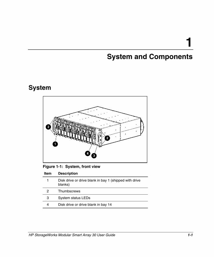
Figure 1-1: System, front view
Item Description
1 Disk drive or drive blank in bay 1 (shipped with drive blanks)
2 Thumbscrews
3 System status LEDs
4 Disk drive or drive blank in bay 14
System and Components
1-2 HP StorageWorks Modular Smart Array 30 User Guide
HP CONFIDENTIAL Writer: Susan Caesar File Name: b-ch1 System and Components.doc
Codename: NorthStar Part Number: 335900-002 Last Saved On: 10/2/03 3:35 PM
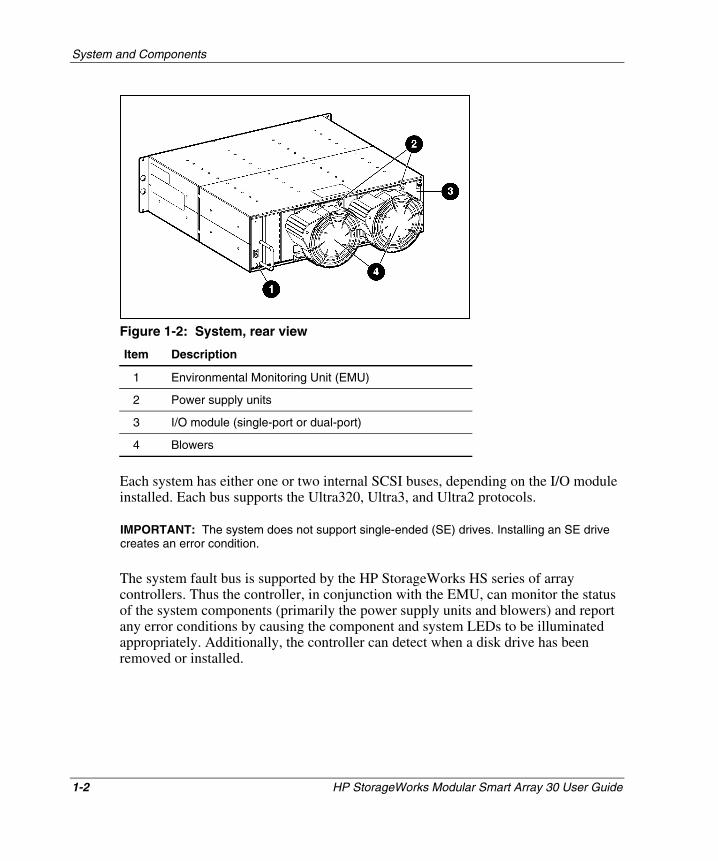
Figure 1-2: System, rear view
Item Description
1 Environmental Monitoring Unit (EMU)
2 Power supply units
3 I/O module (single-port or dual-port)
4 Blowers
Each system has either one or two internal SCSI buses, depending on the I/O module installed. Each bus supports the Ultra320, Ultra3, and Ultra2 protocols.
IMPORTANT: The system does not support single-ended (SE) drives. Installing an SE drive creates an error condition.
The system fault bus is supported by the HP StorageWorks HS series of array controllers. Thus the controller, in conjunction with the EMU, can monitor the status of the system components (primarily the power supply units and blowers) and report any error conditions by causing the component and system LEDs to be illuminated appropriately. Additionally, the controller can detect when a disk drive has been removed or installed.
System and Components
HP StorageWorks Modular Smart Array 30 User Guide 1-3
HP CONFIDENTIAL Writer: Susan Caesar File Name: b-ch1 System and Components.doc
Codename: NorthStar Part Number: 335900-002 Last Saved On: 10/2/03 3:35 PM
Ultra320 I/O Module
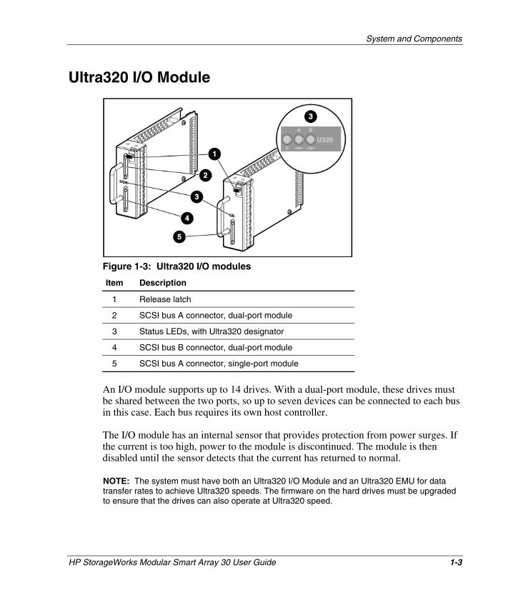
Figure 1-3: Ultra320 I/O modules
Item Description
1 Release latch
2 SCSI bus A connector, dual-port module
3 Status LEDs, with Ultra320 designator
4 SCSI bus B connector, dual-port module
5 SCSI bus A connector, single-port module
An I/O module supports up to 14 drives. With a dual-port module, these drives must be shared between the two ports, so up to seven devices can be connected to each bus in this case. Each bus requires its own host controller.
The I/O module has an internal sensor that provides protection from power surges. If the current is too high, power to the module is discontinued. The module is then disabled until the sensor detects that the current has returned to normal.
NOTE: The system must have both an Ultra320 I/O Module and an Ultra320 EMU for data transfer rates to achieve Ultra320 speeds. The firmware on the hard drives must be upgraded to ensure that the drives can also operate at Ultra320 speed.
System and Components
1-4 HP StorageWorks Modular Smart Array 30 User Guide
HP CONFIDENTIAL Writer: Susan Caesar File Name: b-ch1 System and Components.doc
Codename: NorthStar Part Number: 335900-002 Last Saved On: 10/2/03 3:35 PM
Environmental Monitoring Unit
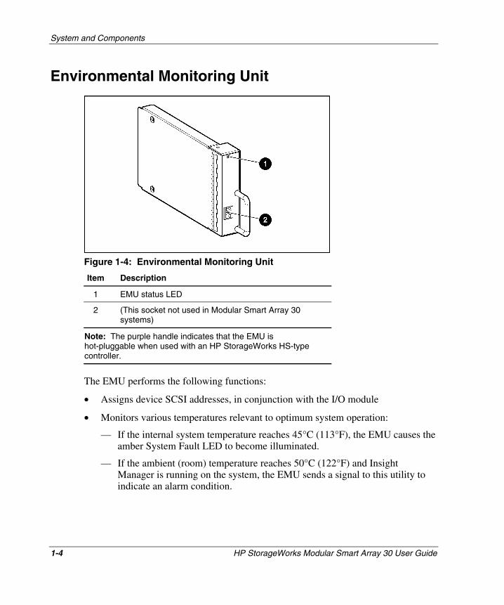
Figure 1-4: Environmental Monitoring Unit
Item Description
1 EMU status LED
2 (This socket not used in Modular Smart Array 30 systems)
Note: The purple handle indicates that the EMU is hot-pluggable when used with an HP StorageWorks HS-type controller.
The EMU performs the following functions:
• Assigns device SCSI addresses, in conjunction with the I/O module
• Monitors various temperatures relevant to optimum system operation:
— If the internal system temperature reaches 45°C (113°F), the EMU causes the amber System Fault LED to become illuminated.
— If the ambient (room) temperature reaches 50°C (122°F) and Insight Manager is running on the system, the EMU sends a signal to this utility to indicate an alarm condition.
System and Components
HP StorageWorks Modular Smart Array 30 User Guide 1-5
HP CONFIDENTIAL Writer: Susan Caesar File Name: b-ch1 System and Components.doc
Codename: NorthStar Part Number: 335900-002 Last Saved On: 10/2/03 3:35 PM
— If the internal temperature of a power supply unit exceeds 85°C (185°F), the power supply unit automatically shuts down.
• Monitors and reports the status of the power supply units, blowers, and system (when the SCSI adapter or RAID controller supports this function):
— If the controller detects a device fault, it can send a signal to the EMU to blink the specific device status LED rapidly.
— If the user requests identification of a device, the controller can cause the EMU to blink the status LED of the specific device slowly.
NOTE: The system must have both an Ultra320 I/O Module and an Ultra320 EMU for data transfer rates to achieve Ultra320 speeds. The firmware on the hard drives must be upgraded to ensure that the drives can also operate at Ultra320 speed.
System and Components
1-6 HP StorageWorks Modular Smart Array 30 User Guide
HP CONFIDENTIAL Writer: Susan Caesar File Name: b-ch1 System and Components.doc
Codename: NorthStar Part Number: 335900-002 Last Saved On: 10/2/03 3:35 PM
Disk Drive and Drive Blank
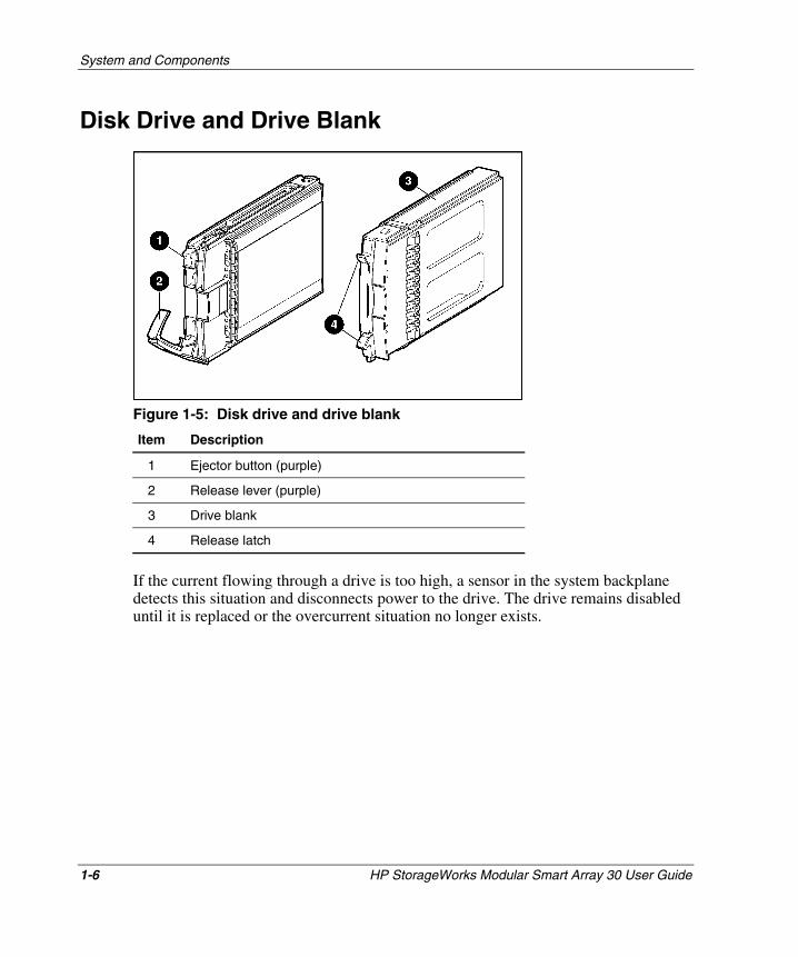
Figure 1-5: Disk drive and drive blank
Item Description
1 Ejector button (purple)
2 Release lever (purple)
3 Drive blank
4 Release latch
If the current flowing through a drive is too high, a sensor in the system backplane detects this situation and disconnects power to the drive. The drive remains disabled until it is replaced or the overcurrent situation no longer exists.
System and Components
HP StorageWorks Modular Smart Array 30 User Guide 1-7
HP CONFIDENTIAL Writer: Susan Caesar File Name: b-ch1 System and Components.doc
Codename: NorthStar Part Number: 335900-002 Last Saved On: 10/2/03 3:35 PM
Power Supply and Blower Assembly
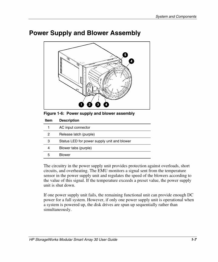
Figure 1-6: Power supply and blower assembly
Item Description
1 AC input connector
2 Release latch (purple)
3 Status LED for power supply unit and blower
4 Blower tabs (purple)
5 Blower
The circuitry in the power supply unit provides protection against overloads, short circuits, and overheating. The EMU monitors a signal sent from the temperature sensor in the power supply unit and regulates the speed of the blowers according to the value of this signal. If the temperature exceeds a preset value, the power supply unit is shut down.
If one power supply unit fails, the remaining functional unit can provide enough DC power for a full system. However, if only one power supply unit is operational when a system is powered up, the disk drives are spun up sequentially rather than simultaneously.

HP StorageWorks Modular Smart Array 30 User Guide 2-1
HP CONFIDENTIAL Writer: Susan Caesar File Name: c-ch2 Installing the System in a Rack.doc
Codename: NorthStar Part Number: 335900-002 Last Saved On: 10/2/03 3:49 PM
2 Installing the System in a Rack
Before installing the system in a rack, remove the internal components to reduce the total weight of the system and make it safer and easier to install.
44 kg (96 lb) in carton
49 kg (108 lb) with pallet
WARNING: Use a forklift or a hand truck to move a system that is still in its shipping container.
Removing the System Components
IMPORTANT: The following abbreviated instructions are appropriate for removing the components from a system that is not being used. To remove individual components from a working system, refer to the complete instructions in a later chapter of this guide.
Drive Blanks
Squeeze the release latches on the drive blank and hold them in while pulling the drive blank out of the system.
Disk Drives 1. Press the purple ejector button.
2. Pivot the release lever to the fully open position.
3. Pull the drive out of the system.

Installing the System in a Rack
2-2 HP StorageWorks Modular Smart Array 30 User Guide
HP CONFIDENTIAL Writer: Susan Caesar File Name: c-ch2 Installing the System in a Rack.doc
Codename: NorthStar Part Number: 335900-002 Last Saved On: 10/2/03 3:49 PM
Power Supply Assembly
Grasp the power supply assembly by the blower unit, lift and hold the purple release latch, and pull the assembly out of the system.
EMU
Grasp the purple handle on the EMU, and pull the EMU out of the system.
I/O Module
Grasp the handle, press and hold the purple release latch, and pull the module out of the system.
Mounting the System in a Rack
11 kg (24 lb) empty
31 kg (68 lb) full
WARNING: Use at least two people to move or install a system. For greater safety and easier installation, reduce the system weight by removing the disk drives, power supply units, blowers, EMU, and I/O module. This procedure reduces the system weight to approximately 11 kg (24 lb). Although a single person can lift this amount, the empty system is still awkward to install because of its physical size.
IMPORTANT: The following procedure describes installation in a square-hole rack. For information about installing the system in a round-hole rack, refer to the rack documentation.
Each disk system requires a vertical rack space of 3U (equivalent to 133 mm, or 5.25 in.).
WARNING: The weight of a system when full exceeds 31 kg (68 lb). Install the system in the lowest available position in the rack.
1. Using the rack template in the system kit as a guide, make pencil marks on the rack to indicate where the rails for the system are to be located.

Installing the System in a Rack
HP StorageWorks Modular Smart Array 30 User Guide 2-3
HP CONFIDENTIAL Writer: Susan Caesar File Name: c-ch2 Installing the System in a Rack.doc
Codename: NorthStar Part Number: 335900-002 Last Saved On: 10/2/03 3:49 PM
a. Align the lower edge of the template with the bottom of the rack (or the top of the previous rack component) and push the tabs in to hold the template in place. Be sure that the template is horizontal.
b. Mark the required location of the rails on the rack.
c. Repeat this procedure to mark the back of the rack, using the back of the template.
2. Identify the left (L) and right (R) rack rails by markings stamped on the sheet metal.
WARNING: Unless you are converting the rails for use in round-hole racks, do not remove the load-bearing pins from the ends of the rack rails.

Installing the System in a Rack
2-4 HP StorageWorks Modular Smart Array 30 User Guide
HP CONFIDENTIAL Writer: Susan Caesar File Name: c-ch2 Installing the System in a Rack.doc
Codename: NorthStar Part Number: 335900-002 Last Saved On: 10/2/03 3:49 PM
3. Slide the front end of the left rack rail toward the inside front of the rack until the scissor-type locking latch engages with the rack upright.
4. Confirm that the rail pins extend through the U-holes that were marked in step 1. If this is not the case, repeat step 3.
5. Extend the back end of the left rack rail toward the inside rear of the rack until the scissor-type locking latch engages with the rack upright.
6. Confirm that the rail pins extend through the U-holes that were marked in step 1. If this is not the case, repeat step 5.
Installing the System in a Rack
HP StorageWorks Modular Smart Array 30 User Guide 2-5
HP CONFIDENTIAL Writer: Susan Caesar File Name: c-ch2 Installing the System in a Rack.doc
Codename: NorthStar Part Number: 335900-002 Last Saved On: 10/2/03 3:49 PM
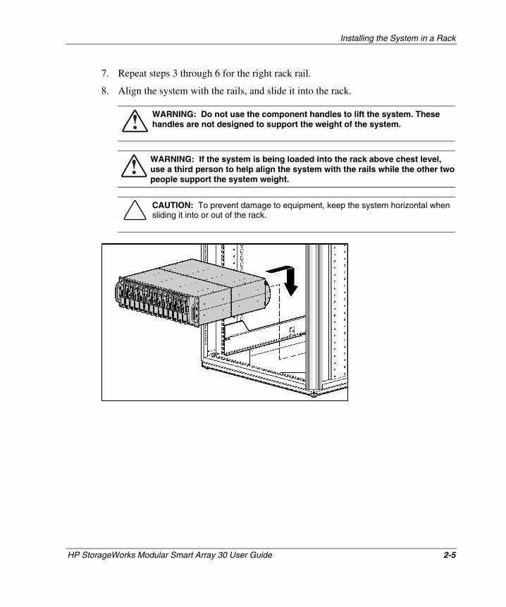
7. Repeat steps 3 through 6 for the right rack rail.
8. Align the system with the rails, and slide it into the rack.
WARNING: Do not use the component handles to lift the system. These handles are not designed to support the weight of the system.
WARNING: If the system is being loaded into the rack above chest level, use a third person to help align the system with the rails while the other two people support the system weight.
CAUTION: To prevent damage to equipment, keep the system horizontal when sliding it into or out of the rack.
Installing the System in a Rack
2-6 HP StorageWorks Modular Smart Array 30 User Guide
HP CONFIDENTIAL Writer: Susan Caesar File Name: c-ch2 Installing the System in a Rack.doc
Codename: NorthStar Part Number: 335900-002 Last Saved On: 10/2/03 3:49 PM
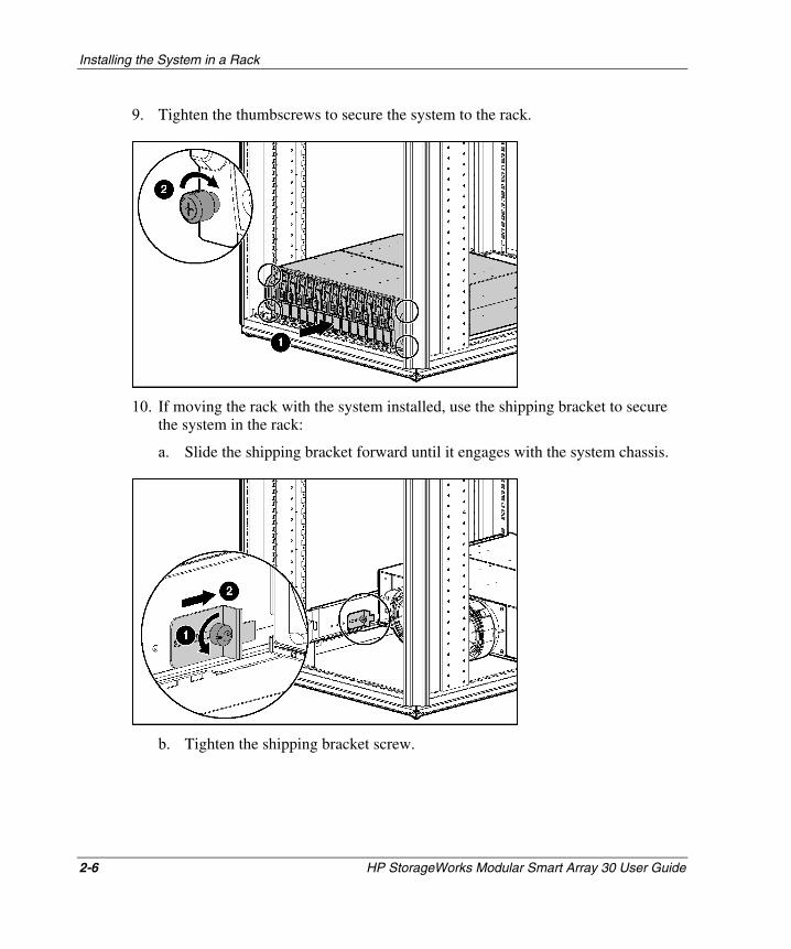
9. Tighten the thumbscrews to secure the system to the rack.
10. If moving the rack with the system installed, use the shipping bracket to secure the system in the rack:
a. Slide the shipping bracket forward until it engages with the system chassis.
b. Tighten the shipping bracket screw.
Installing the System in a Rack
HP StorageWorks Modular Smart Array 30 User Guide 2-7
HP CONFIDENTIAL Writer: Susan Caesar File Name: c-ch2 Installing the System in a Rack.doc
Codename: NorthStar Part Number: 335900-002 Last Saved On: 10/2/03 3:49 PM
Completing the Installation 1. Reinstall the components in the system. For details, refer to Chapter 3.
2. Connect cables from the VHDCI sockets on the I/O modules to the corresponding connectors on a controller system. If you need additional cables, order according to the information in the following table.
Table 2-1: Supported SCSI Cables
Connector Type Length Part Number
Standard Cables
68-pin VHDCI 3.0 m (10 ft) 189505-B21
68-pin Offset VHDCI 3.7 m (12 ft) 342175-B21
Optional Cables
68-pin VHDCI 1.0 m (3.3 ft)
2.0 m (6.6 ft)
5.0 m (16 ft)
168256-B21
168257-B21
116454-B21
68-pin Offset VHDCI 1.8 m (6 ft)
7.3 m (24 ft)
12 m (39 ft)
341174-B21
164604-B21
150214-B21
3. Connect the AC input sockets of each power supply unit to an AC power source.
CAUTION: The disk system does not have power switches. Be sure that the system is correctly configured before connecting the power cords.
NOTE: Having two power supply units eliminates the power supply unit as a single point of failure. This is the preferred, high-availability configuration. For complete power redundancy, each power supply unit should be connected to a separate AC power source.
4. Confirm that the system components are all functioning normally by observing the condition of their status LEDs, as described in the next section.
Installing the System in a Rack
2-8 HP StorageWorks Modular Smart Array 30 User Guide
HP CONFIDENTIAL Writer: Susan Caesar File Name: c-ch2 Installing the System in a Rack.doc
Codename: NorthStar Part Number: 335900-002 Last Saved On: 10/2/03 3:49 PM
Verifying Normal Operation
System LEDs
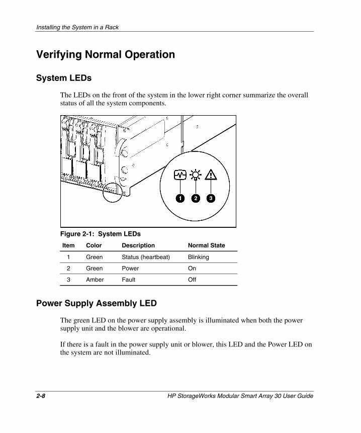
The LEDs on the front of the system in the lower right corner summarize the overall status of all the system components.
Figure 2-1: System LEDs
Item Color Description Normal State
1 Green Status (heartbeat) Blinking
2 Green Power On
3 Amber Fault Off
Power Supply Assembly LED
The green LED on the power supply assembly is illuminated when both the power supply unit and the blower are operational.
If there is a fault in the power supply unit or blower, this LED and the Power LED on the system are not illuminated.
Installing the System in a Rack
HP StorageWorks Modular Smart Array 30 User Guide 2-9
HP CONFIDENTIAL Writer: Susan Caesar File Name: c-ch2 Installing the System in a Rack.doc
Codename: NorthStar Part Number: 335900-002 Last Saved On: 10/2/03 3:49 PM
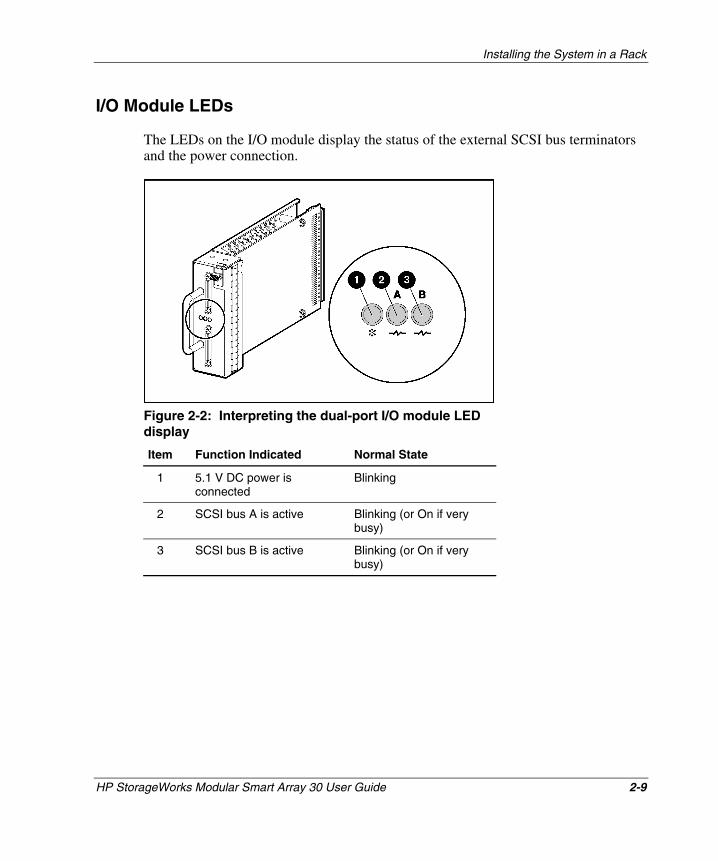
I/O Module LEDs
The LEDs on the I/O module display the status of the external SCSI bus terminators and the power connection.
Figure 2-2: Interpreting the dual-port I/O module LED display
Item Function Indicated Normal State
1 5.1 V DC power is connected
Blinking
2 SCSI bus A is active Blinking (or On if very busy)
3 SCSI bus B is active Blinking (or On if very busy)
Installing the System in a Rack
2-10 HP StorageWorks Modular Smart Array 30 User Guide
HP CONFIDENTIAL Writer: Susan Caesar File Name: c-ch2 Installing the System in a Rack.doc
Codename: NorthStar Part Number: 335900-002 Last Saved On: 10/2/03 3:49 PM
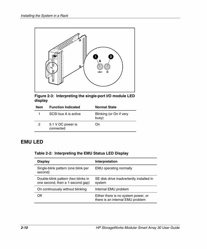
Figure 2-3: Interpreting the single-port I/O module LED display
Item Function Indicated Normal State
1 SCSI bus A is active Blinking (or On if very busy)
2 5.1 V DC power is connected
On
EMU LED
Table 2-2: Interpreting the EMU Status LED Display
Display Interpretation
Single-blink pattern (one blink per second)
EMU operating normally
Double-blink pattern (two blinks in one second, then a 1-second gap)
SE disk drive inadvertently installed in system
On continuously without blinking Internal EMU problem
Off Either there is no system power, or there is an internal EMU problem
Installing the System in a Rack
HP StorageWorks Modular Smart Array 30 User Guide 2-11
HP CONFIDENTIAL Writer: Susan Caesar File Name: c-ch2 Installing the System in a Rack.doc
Codename: NorthStar Part Number: 335900-002 Last Saved On: 10/2/03 3:49 PM
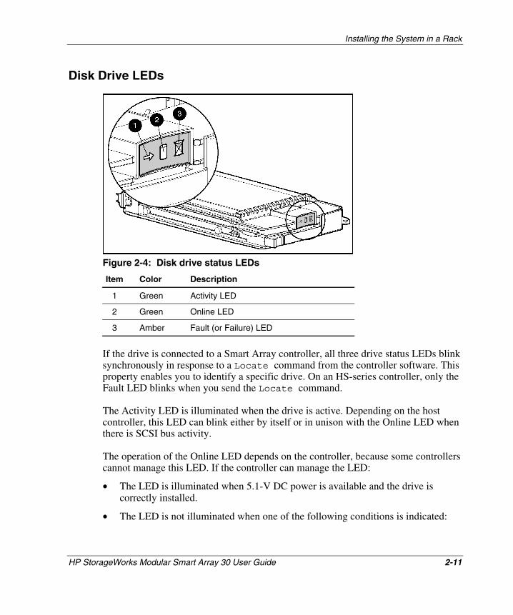
Disk Drive LEDs
Figure 2-4: Disk drive status LEDs
Item Color Description
1 Green Activity LED
2 Green Online LED
3 Amber Fault (or Failure) LED
If the drive is connected to a Smart Array controller, all three drive status LEDs blink synchronously in response to a Locate command from the controller software. This property enables you to identify a specific drive. On an HS-series controller, only the Fault LED blinks when you send the Locate command.
The Activity LED is illuminated when the drive is active. Depending on the host controller, this LED can blink either by itself or in unison with the Online LED when there is SCSI bus activity.
The operation of the Online LED depends on the controller, because some controllers cannot manage this LED. If the controller can manage the LED:
• The LED is illuminated when 5.1-V DC power is available and the drive is correctly installed.
• The LED is not illuminated when one of the following conditions is indicated:
Installing the System in a Rack
2-12 HP StorageWorks Modular Smart Array 30 User Guide
HP CONFIDENTIAL Writer: Susan Caesar File Name: c-ch2 Installing the System in a Rack.doc
Codename: NorthStar Part Number: 335900-002 Last Saved On: 10/2/03 3:49 PM
— There is no controller on the bus.
— 5.1-V DC power is not available.
— The drive is not correctly installed in the system.
• The LED blinks either by itself or in unison with the Activity LED when there is SCSI bus activity.
Depending on the host controller, the Fault LED blinks when the controller detects an error condition.
If the host controller can control the illumination status of the drive LEDs, the display patterns for various conditions can be interpreted as shown in Tables 2-2 and 2-3.
CAUTION: Because some controllers cannot control all the drive LEDs, you could misinterpret the display. Refer to the controller documentation before using this table to determine whether the controller is capable of controlling all the LEDs.
Installing the System in a Rack
HP StorageWorks Modular Smart Array 30 User Guide 2-13
HP CONFIDENTIAL Writer: Susan Caesar File Name: c-ch2 Installing the System in a Rack.doc
Codename: NorthStar Part Number: 335900-002 Last Saved On: 10/2/03 3:49 PM
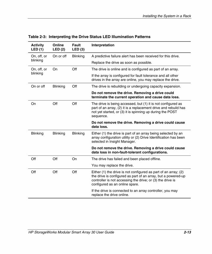
Table 2-3: Interpreting the Drive Status LED Illumination Patterns
Activity LED (1)
Online LED (2)
Fault LED (3)
Interpretation
On, off, or blinking
On or off Blinking A predictive failure alert has been received for this drive.
Replace the drive as soon as possible.
On, off, or blinking
On Off The drive is online and is configured as part of an array.
If the array is configured for fault tolerance and all other drives in the array are online, you may replace the drive.
On or off Blinking Off The drive is rebuilding or undergoing capacity expansion.
Do not remove the drive. Removing a drive could terminate the current operation and cause data loss.
On Off Off The drive is being accessed, but (1) it is not configured as part of an array, (2) it is a replacement drive and rebuild has not yet started, or (3) it is spinning up during the POST sequence.
Do not remove the drive. Removing a drive could cause data loss.
Blinking Blinking Blinking Either (1) the drive is part of an array being selected by an array configuration utility or (2) Drive Identification has been selected in Insight Manager.
Do not remove the drive. Removing a drive could cause data loss in non-fault-tolerant configurations.
Off Off On The drive has failed and been placed offline.
You may replace the drive.
Off Off Off Either (1) the drive is not configured as part of an array; (2) the drive is configured as part of an array, but a powered-up controller is not accessing the drive; or (3) the drive is configured as an online spare.
If the drive is connected to an array controller, you may replace the drive online.
HP StorageWorks Modular Smart Array 30 User Guide 3-1
HP CONFIDENTIAL Writer: Susan Caesar File Name: d-ch3 Replacing System Components.doc
Codename: NorthStar Part Number: 335900-002 Last Saved On: 10/2/03 3:51 PM
3 Replacing System Components
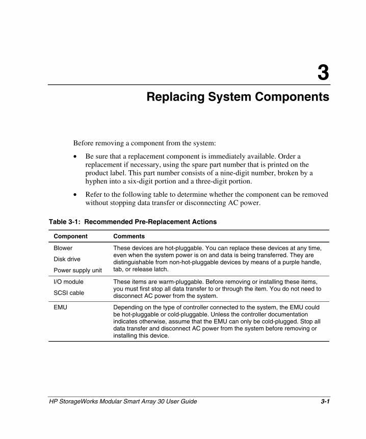
Before removing a component from the system:
• Be sure that a replacement component is immediately available. Order a replacement if necessary, using the spare part number that is printed on the product label. This part number consists of a nine-digit number, broken by a hyphen into a six-digit portion and a three-digit portion.
• Refer to the following table to determine whether the component can be removed without stopping data transfer or disconnecting AC power.
Table 3-1: Recommended Pre-Replacement Actions
Component Comments
Blower
Disk drive
Power supply unit
These devices are hot-pluggable. You can replace these devices at any time, even when the system power is on and data is being transferred. They are distinguishable from non-hot-pluggable devices by means of a purple handle, tab, or release latch.
I/O module
SCSI cable
These items are warm-pluggable. Before removing or installing these items, you must first stop all data transfer to or through the item. You do not need to disconnect AC power from the system.
EMU Depending on the type of controller connected to the system, the EMU could be hot-pluggable or cold-pluggable. Unless the controller documentation indicates otherwise, assume that the EMU can only be cold-plugged. Stop all data transfer and disconnect AC power from the system before removing or installing this device.
Replacing System Components
3-2 HP StorageWorks Modular Smart Array 30 User Guide
HP CONFIDENTIAL Writer: Susan Caesar File Name: d-ch3 Replacing System Components.doc
Codename: NorthStar Part Number: 335900-002 Last Saved On: 10/2/03 3:51 PM
Replacement Procedures
No special tools or techniques are required for replacing any system component.
The following general steps apply to all components. Detailed procedures for individual components are given in the appropriate section in this chapter.
CAUTION: When replacing a component, take the following precautions to minimize the possibility of damage from electrostatic discharge.
• Transport and store components in static-free containers. Do not remove the component from the static-free container until you are ready to install it in the system.
• Avoid touching connector pins, leads, or circuitry.
For further information, refer to Appendix B, “Electrostatic Discharge.”
1. Remove the defective component from the system.
2. Remove the replacement component from its static-free container.
3. Check the label on the replacement component to be sure that it is of the correct type.
4. Align the replacement component with the system guide slots.
5. Slide the replacement component into the system until it is against the backplane connector. Be sure that the component is fully seated in the system.
6. Observe the status LED to confirm that the new component is operating properly.
7. Place the defective component in the static-free container for shipment.
Disk Drive or Drive Blank
The disk system supports up to 14 hot-pluggable, Ultra320 SCSI disk drives. You can also use Ultra3 and Ultra2 drives in the system, but the bus speeds then decrease to the corresponding level.
IMPORTANT: The system does not support SE drives. Installing an SE drive creates an error condition.

Replacing System Components
HP StorageWorks Modular Smart Array 30 User Guide 3-3
HP CONFIDENTIAL Writer: Susan Caesar File Name: d-ch3 Replacing System Components.doc
Codename: NorthStar Part Number: 335900-002 Last Saved On: 10/2/03 3:51 PM
These disk drives mount in the slots (bays) in the front of the system. The bays are numbered consecutively from left to right, starting with bay 1, and drives are commonly referred to by their bay number. This bay number is usually different from the SCSI ID number of the drive. (To determine the SCSI ID of a drive, refer to Appendix D).
When a disk drive fails, both the amber Drive Failure LED and the amber System Fault LED are illuminated.
CAUTION: Removing more than one drive or blank at a time while the system is operating can cause the system to overheat. To prevent overheating, install a disk drive or a drive blank into an empty bay as soon as possible after removing the drive.
Removing a Drive Blank
Squeeze the release latches toward each other and hold them in while pulling the blank out of the system.
Removing a Disk Drive
1. Press the purple ejector button.
2. Pivot the release lever to the fully open position.
3. Pull the drive out by about 3 cm (1 in.) so that it is disconnected from the backplane connector.
CAUTION: A drive with a rapidly spinning disk can be difficult to hold securely. To decrease the chance of dropping the drive, do not remove it completely from the system until the disk has stopped rotating. This usually takes a few seconds.
4. When the disk is no longer spinning, remove the drive from the system.
Installing a Drive Blank
Insert the drive blank into the system and push it in.

Replacing System Components
3-4 HP StorageWorks Modular Smart Array 30 User Guide
HP CONFIDENTIAL Writer: Susan Caesar File Name: d-ch3 Replacing System Components.doc
Codename: NorthStar Part Number: 335900-002 Last Saved On: 10/2/03 3:51 PM
Installing a Replacement Drive
IMPORTANT: Be sure that the replacement drive is using the latest firmware before installing it in the system. Otherwise, the system may not be able to operate at Ultra320 speed.
1. Insert the replacement drive into the bay until the drive is against the backplane connector.
2. Push the release lever in until it engages the ejector button.
3. Observe the drive status LEDs to confirm that the replacement drive is functioning correctly.
Blower
WARNING: The blower blades rotate at a high speed and do not stop immediately when power is disconnected. Allow enough time for the blades to stop rotating before removing the blower from the power supply unit.
1. Remove the blower from the power supply unit by pressing the two purple blower tabs (3) while pulling the blower toward you.
2. Align the guidepost (2) on the replacement blower with the hole (1) adjacent to the DC power outlet.
Replacing System Components
HP StorageWorks Modular Smart Array 30 User Guide 3-5
HP CONFIDENTIAL Writer: Susan Caesar File Name: d-ch3 Replacing System Components.doc
Codename: NorthStar Part Number: 335900-002 Last Saved On: 10/2/03 3:51 PM
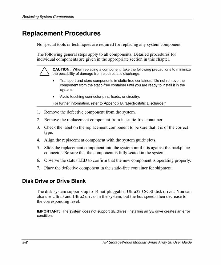
3. Slide the replacement blower into the blower base (4) until the blower tabs snap into place. Be sure that there is no gap between the blower base and the blower.
CAUTION: To prevent damage to the blower, press mostly on the blower rim when installing the blower on the power supply unit. Do not apply excessive force to the vents on the front of the blower.
4. Confirm that the blower starts operating immediately and that the blower LED is illuminated.
Power Supply Unit
CAUTION: To prevent the system from overheating and possibly shutting down while you remove a power supply unit, install the replacement unit as soon as possible after removing the defective unit.
1. Disconnect the AC power cord from the defective power supply unit.
2. While lifting the latch (2), grasp the blower body (5) and pull the defective power supply unit out of the system.
3. Remove the operational blower from the defective power supply unit by pressing the two purple blower tabs (4) while pulling the blower element toward you.
4. Install the blower on the replacement power supply unit as described in the blower replacement section.

Replacing System Components
3-6 HP StorageWorks Modular Smart Array 30 User Guide
HP CONFIDENTIAL Writer: Susan Caesar File Name: d-ch3 Replacing System Components.doc
Codename: NorthStar Part Number: 335900-002 Last Saved On: 10/2/03 3:51 PM
5. Lift up the latch (2) and hold it in place while inserting the replacement power supply assembly into the empty bay. Confirm that the unit is fully seated in the system.
6. Connect the AC power cord.
7. Confirm that:
— The blower starts operating immediately.
— The LED (3) is illuminated.
— The blower on the other power supply unit is no longer operating at a high speed.
EMU
CAUTION: Removing the EMU causes a significant change in the airflow within the system. To prevent the system from overheating, replace the EMU as quickly as possible.
IMPORTANT: Be sure that the replacement EMU is Ultra320-compatible.
1. Pull the EMU out of the system.
Replacing System Components
HP StorageWorks Modular Smart Array 30 User Guide 3-7
HP CONFIDENTIAL Writer: Susan Caesar File Name: d-ch3 Replacing System Components.doc
Codename: NorthStar Part Number: 335900-002 Last Saved On: 10/2/03 3:51 PM
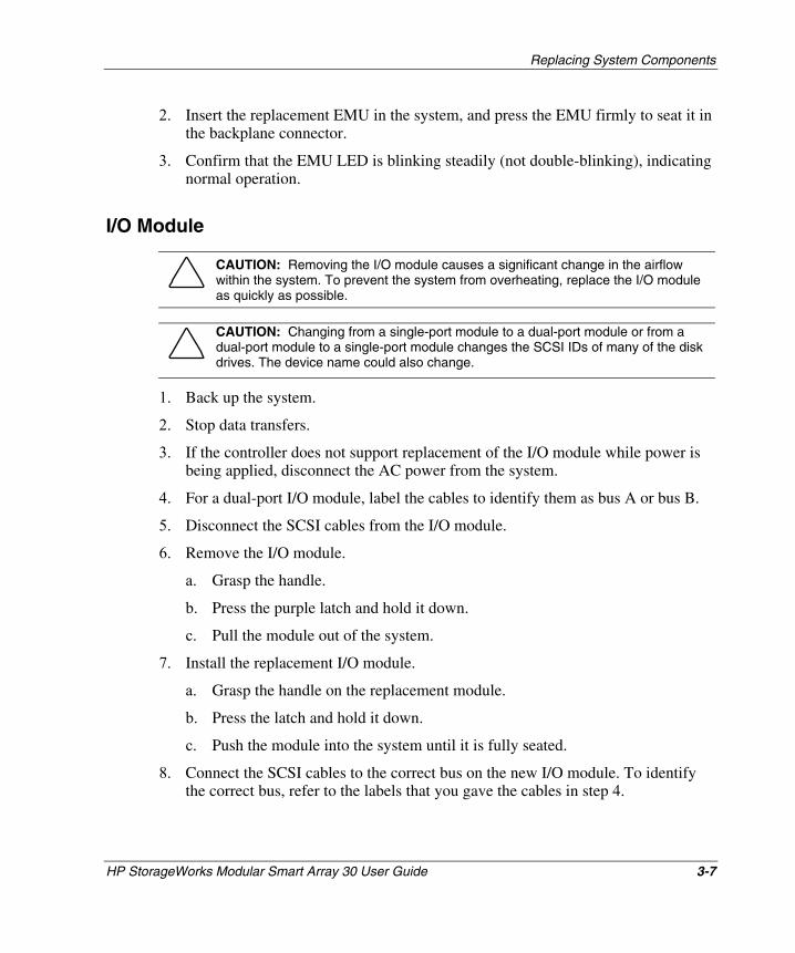
2. Insert the replacement EMU in the system, and press the EMU firmly to seat it in the backplane connector.
3. Confirm that the EMU LED is blinking steadily (not double-blinking), indicating normal operation.
I/O Module
CAUTION: Removing the I/O module causes a significant change in the airflow within the system. To prevent the system from overheating, replace the I/O module as quickly as possible.
CAUTION: Changing from a single-port module to a dual-port module or from a dual-port module to a single-port module changes the SCSI IDs of many of the disk drives. The device name could also change.
1. Back up the system.
2. Stop data transfers.
3. If the controller does not support replacement of the I/O module while power is being applied, disconnect the AC power from the system.
4. For a dual-port I/O module, label the cables to identify them as bus A or bus B.
5. Disconnect the SCSI cables from the I/O module.
6. Remove the I/O module.
a. Grasp the handle.
b. Press the purple latch and hold it down.
c. Pull the module out of the system.
7. Install the replacement I/O module.
a. Grasp the handle on the replacement module.
b. Press the latch and hold it down.
c. Push the module into the system until it is fully seated.
8. Connect the SCSI cables to the correct bus on the new I/O module. To identify the correct bus, refer to the labels that you gave the cables in step 4.

Replacing System Components
3-8 HP StorageWorks Modular Smart Array 30 User Guide
HP CONFIDENTIAL Writer: Susan Caesar File Name: d-ch3 Replacing System Components.doc
Codename: NorthStar Part Number: 335900-002 Last Saved On: 10/2/03 3:51 PM
CAUTION: To prevent damage to the cable connector, do not use excessive force to tighten the thumbscrews on the connector.
9. If power was disconnected in step 3, reconnect AC power to the system.
10. Observe the I/O module LEDs to confirm that the module is functioning properly.
HP StorageWorks Modular Smart Array 30 User Guide A-1
HP CONFIDENTIAL Writer: Susan Caesar File Name: e-appa Regulatory Compliance Notices.doc
Codename: NorthStar Part Number: 335900-002 Last Saved On: 10/2/03 3:52 PM
A Regulatory Compliance Notices
Federal Communications Commission Notice
Part 15 of the Federal Communications Commission (FCC) Rules and Regulations has established Radio Frequency (RF) emission limits to provide an interference-free radio frequency spectrum. Many electronic devices, including computers, generate RF energy incidental to their intended function and are, therefore, covered by these rules. These rules place computers and related peripheral devices into two classes, A and B, depending upon their intended installation. Class A devices are those that may reasonably be expected to be installed in a business or commercial environment. Class B devices are those that may reasonably be expected to be installed in a residential environment (for example, personal computers). The FCC requires devices in both classes to bear a label indicating the interference potential of the device as well as additional operating instructions for the user.
The FCC rating label on the device shows the classification (A or B) of the equipment. Class B devices have an FCC logo or FCC ID on the label. Class A devices do not have an FCC logo or FCC ID on the label. After the Class of the device is determined, refer to the corresponding statement in the following sections.
Regulatory Compliance Notices
A-2 HP StorageWorks Modular Smart Array 30 User Guide
HP CONFIDENTIAL Writer: Susan Caesar File Name: e-appa Regulatory Compliance Notices.doc
Codename: NorthStar Part Number: 335900-002 Last Saved On: 10/2/03 3:52 PM
Class A Equipment
This equipment has been tested and found to comply with the limits for a Class A digital device, pursuant to Part 15 of the FCC Rules. These limits are designed to provide reasonable protection against harmful interference when the equipment is operated in a commercial environment. This equipment generates, uses, and can radiate radio frequency energy and, if not installed and used in accordance with the instructions, may cause harmful interference to radio communications. Operation of this equipment in a residential area is likely to cause harmful interference, in which case the user will be required to correct the interference at personal expense.
Class B Equipment
This equipment has been tested and found to comply with the limits for a Class B digital device, pursuant to Part 15 of the FCC Rules. These limits are designed to provide reasonable protection against harmful interference in a residential installation. This equipment generates, uses, and can radiate radio frequency energy and, if not installed and used in accordance with the instructions, may cause harmful interference to radio communications. However, there is no guarantee that interference will not occur in a particular installation. If this equipment does cause harmful interference to radio or television reception, which can be determined by turning the equipment off and on, the user is encouraged to try to correct the interference by one or more of the following measures:
• Reorient or relocate the receiving antenna.
• Increase the separation between the equipment and receiver.
• Connect the equipment into an outlet on a circuit that is different from that to which the receiver is connected.
• Consult the dealer or an experienced radio or television technician for help.
Regulatory Compliance Notices
HP StorageWorks Modular Smart Array 30 User Guide A-3
HP CONFIDENTIAL Writer: Susan Caesar File Name: e-appa Regulatory Compliance Notices.doc
Codename: NorthStar Part Number: 335900-002 Last Saved On: 10/2/03 3:52 PM
Declaration of Conformity for Products Marked with the FCC Logo, United States Only
This device complies with Part 15 of the FCC Rules. Operation is subject to the following two conditions: (1) this device may not cause harmful interference, and (2) this device must accept any interference received, including interference that may cause undesired operation.
For questions regarding your product, contact us by mail or telephone:
• Hewlett-Packard Company P. O. Box 692000, Mail Stop 530113 Houston, Texas 77269-2000
• 1-800-652-6672 (For continuous quality improvement, calls may be recorded or monitored.)
For questions regarding this FCC declaration, contact us by mail or telephone:
• Hewlett-Packard Company P. O. Box 692000, Mail Stop 510101 Houston, Texas 77269-2000
• 1-281-514-3333
To identify this product, refer to the part, series, or model number found on the product.
Modifications
The FCC requires the user to be notified that any changes or modifications made to this device that are not expressly approved by Hewlett-Packard Company may void the user’s authority to operate the equipment.
Cables
Connections to this device must be made with shielded cables with metallic RFI/EMI connector hoods in order to maintain compliance with FCC Rules and Regulations.

Regulatory Compliance Notices
A-4 HP StorageWorks Modular Smart Array 30 User Guide
HP CONFIDENTIAL Writer: Susan Caesar File Name: e-appa Regulatory Compliance Notices.doc
Codename: NorthStar Part Number: 335900-002 Last Saved On: 10/2/03 3:52 PM
Canadian Notice (Avis Canadien)
Class A Equipment
This Class A digital apparatus meets all requirements of the Canadian Interference-Causing Equipment Regulations.
Cet appareil numérique de la classe A respecte toutes les exigences du Règlement sur le matériel brouilleur du Canada.
Class B Equipment
This Class B digital apparatus meets all requirements of the Canadian Interference-Causing Equipment Regulations.
Cet appareil numérique de la classe B respecte toutes les exigences du Règlement sur le matériel brouilleur du Canada.
European Union Notice
Products with the CE Marking comply with both the EMC Directive (89/336/EEC) and the Low Voltage Directive (73/23/EEC) issued by the Commission of the European Community.
Compliance with these directives implies conformity to the following European Norms (the equivalent international standards are in parentheses):
• EN55022 (CISPR 22) – Electromagnetic Interference
• EN55024 (IEC61000-4-2, 3, 4, 5, 6, 8, 11) – Electromagnetic Immunity
• EN61000-3-2 (IEC61000-3-2) – Power Line Harmonics
• EN61000-3-3 (IEC61000-3-3) – Power Line Flicker
• EN60950 (IEC950) – Product Safety
Regulatory Compliance Notices
HP StorageWorks Modular Smart Array 30 User Guide A-5
HP CONFIDENTIAL Writer: Susan Caesar File Name: e-appa Regulatory Compliance Notices.doc
Codename: NorthStar Part Number: 335900-002 Last Saved On: 10/2/03 3:52 PM
Japanese Notice
Regulatory Compliance Notices
A-6 HP StorageWorks Modular Smart Array 30 User Guide
HP CONFIDENTIAL Writer: Susan Caesar File Name: e-appa Regulatory Compliance Notices.doc
Codename: NorthStar Part Number: 335900-002 Last Saved On: 10/2/03 3:52 PM
Korean Notice
Class A Equipment
Class B Equipment
BSMI Notice

HP Storage Works Modular Smart Array 30 User Guide B-1
COMPAQ CONFIDENTIAL Writer: Susan Caesar File Name: f-appb Electrostatic Discharge.doc
Codename: northstar Part Number: 335900-002 Last Saved On: 10/2/03 3:53 PM
B Electrostatic Discharge
Preventing Electrostatic Damage
A discharge of static electricity from a finger or other conductor may damage system boards or other static-sensitive devices. This type of damage may reduce the life expectancy of the device.
To prevent electrostatic damage when setting up the system or handling parts:
• Avoid hand contact by transporting and storing products in static-safe containers.
• Keep electrostatic-sensitive parts in their containers until they arrive at static-free workstations.
• Place parts on a grounded surface before removing them from their containers.
• Avoid touching pins, leads, or circuitry.
• Always be properly grounded when touching a static-sensitive component or assembly.
Electrostatic Discharge
B-2 HP Storage Works Modular Smart Array 30 User Guide
COMPAQ CONFIDENTIAL Writer: Susan Caesar File Name: f-appb Electrostatic Discharge.doc
Codename: northstar Part Number: 335900-002 Last Saved On: 10/2/03 3:53 PM
Grounding Methods to Prevent Electrostatic Damage
There are several methods for grounding. Use one or more of the following methods when handling or installing electrostatic-sensitive parts:
• Use a wrist strap connected by a ground cord to a grounded workstation or computer chassis. Wrist straps are flexible straps with a minimum of 1 megohm ± 10 percent resistance in the ground cords. To provide proper ground, wear the strap snug tightly against the skin.
• Use heel straps, toe straps, or boot straps at standing workstations. Wear the straps on both feet when standing on conductive floors or dissipating floor mats.
• Use conductive field service tools.
• Use a portable field service kit with a folding static-dissipating work mat.
If you do not have any of the suggested equipment for proper grounding, have an authorized reseller install the part.
For more information on static electricity, or assistance with product installation, contact your authorized reseller.

HP StorageWorks Modular Smart Array 30 User Guide C-1
HP CONFIDENTIAL Writer: Susan Caesar File Name: g-appc Specifications.doc
Codename: NorthStar Part Number: 335900-002 Last Saved On: 10/2/03 3:58 PM
C Specifications
Power Specifications
Table C-1: Power Specifications
Nominal Value Range
AC Input
Frequency (±5%) 50 to 60 Hz 47 to 63 Hz
Voltage 110 or 240 V 90 to 254 V RMS (autoranging)
Steady state maximum current 1.5 A at 240 V
3.6 A at 110 V
—
DC Output
Total Power 377 W Maximum 475 W
+5.1 V initial voltage 5.15 V 5.10 to 5.20 V
+5.1 V steady state current 20.0 A Maximum 28.0 A
+12.1 V (disks) initial voltage 12.25 V 12.13 to 12.37 V
+12.1 V (disks) steady state current 20.0 A Maximum 31.5 A
+12.5 V (blowers) initial voltage 12.5 V 12.25 to 12.75 V
+12.5 V (blowers) steady state current Depends on blower speed
Maximum 2.5 A
Specifications
C-2 HP StorageWorks Modular Smart Array 30 User Guide
HP CONFIDENTIAL Writer: Susan Caesar File Name: g-appc Specifications.doc
Codename: NorthStar Part Number: 335900-002 Last Saved On: 10/2/03 3:58 PM
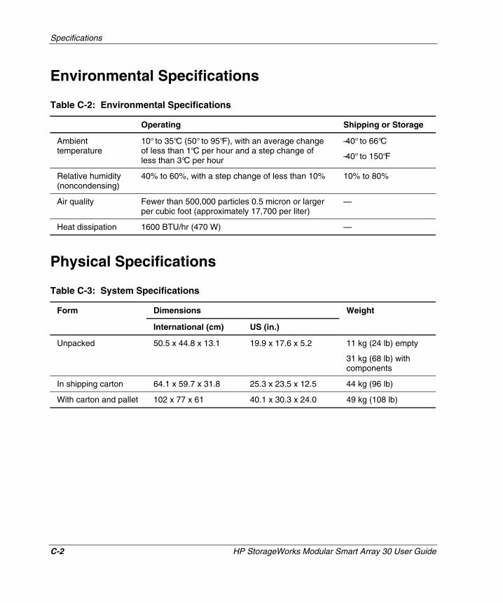
Environmental Specifications
Table C-2: Environmental Specifications
Operating Shipping or Storage
Ambient temperature
10° to 35°C (50° to 95°F), with an average change of less than 1°C per hour and a step change of less than 3°C per hour
–40° to 66°C
–40° to 150°F
Relative humidity (noncondensing)
40% to 60%, with a step change of less than 10% 10% to 80%
Air quality Fewer than 500,000 particles 0.5 micron or larger per cubic foot (approximately 17,700 per liter)
—
Heat dissipation 1600 BTU/hr (470 W) —
Physical Specifications
Table C-3: System Specifications
Dimensions Form
International (cm) US (in.)
Weight
Unpacked 50.5 x 44.8 x 13.1 19.9 x 17.6 x 5.2 11 kg (24 lb) empty
31 kg (68 lb) with components
In shipping carton 64.1 x 59.7 x 31.8 25.3 x 23.5 x 12.5 44 kg (96 lb)
With carton and pallet 102 x 77 x 61 40.1 x 30.3 x 24.0 49 kg (108 lb)
Specifications
HP StorageWorks Modular Smart Array 30 User Guide C-3
HP CONFIDENTIAL Writer: Susan Caesar File Name: g-appc Specifications.doc
Codename: NorthStar Part Number: 335900-002 Last Saved On: 10/2/03 3:58 PM
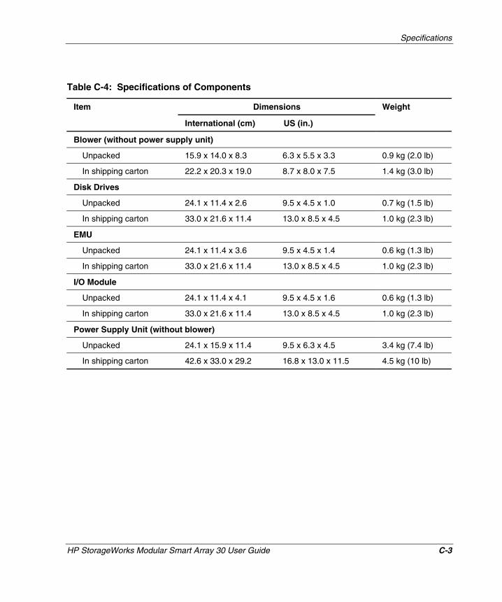
Table C-4: Specifications of Components
Dimensions Item
International (cm) US (in.)
Weight
Blower (without power supply unit)
Unpacked 15.9 x 14.0 x 8.3 6.3 x 5.5 x 3.3 0.9 kg (2.0 lb)
In shipping carton 22.2 x 20.3 x 19.0 8.7 x 8.0 x 7.5 1.4 kg (3.0 lb)
Disk Drives
Unpacked 24.1 x 11.4 x 2.6 9.5 x 4.5 x 1.0 0.7 kg (1.5 lb)
In shipping carton 33.0 x 21.6 x 11.4 13.0 x 8.5 x 4.5 1.0 kg (2.3 lb)
EMU
Unpacked 24.1 x 11.4 x 3.6 9.5 x 4.5 x 1.4 0.6 kg (1.3 lb)
In shipping carton 33.0 x 21.6 x 11.4 13.0 x 8.5 x 4.5 1.0 kg (2.3 lb)
I/O Module
Unpacked 24.1 x 11.4 x 4.1 9.5 x 4.5 x 1.6 0.6 kg (1.3 lb)
In shipping carton 33.0 x 21.6 x 11.4 13.0 x 8.5 x 4.5 1.0 kg (2.3 lb)
Power Supply Unit (without blower)
Unpacked 24.1 x 15.9 x 11.4 9.5 x 6.3 x 4.5 3.4 kg (7.4 lb)
In shipping carton 42.6 x 33.0 x 29.2 16.8 x 13.0 x 11.5 4.5 kg (10 lb)
HP StorageWorks Modular Smart Array 30 User Guide D-1
HP CONFIDENTIAL Writer: Susan Caesar File Name: h-appd SCSI address map.doc
Codename: NorthStar Part Number: 335900-002 Last Saved On: 10/2/03 4:01 PM
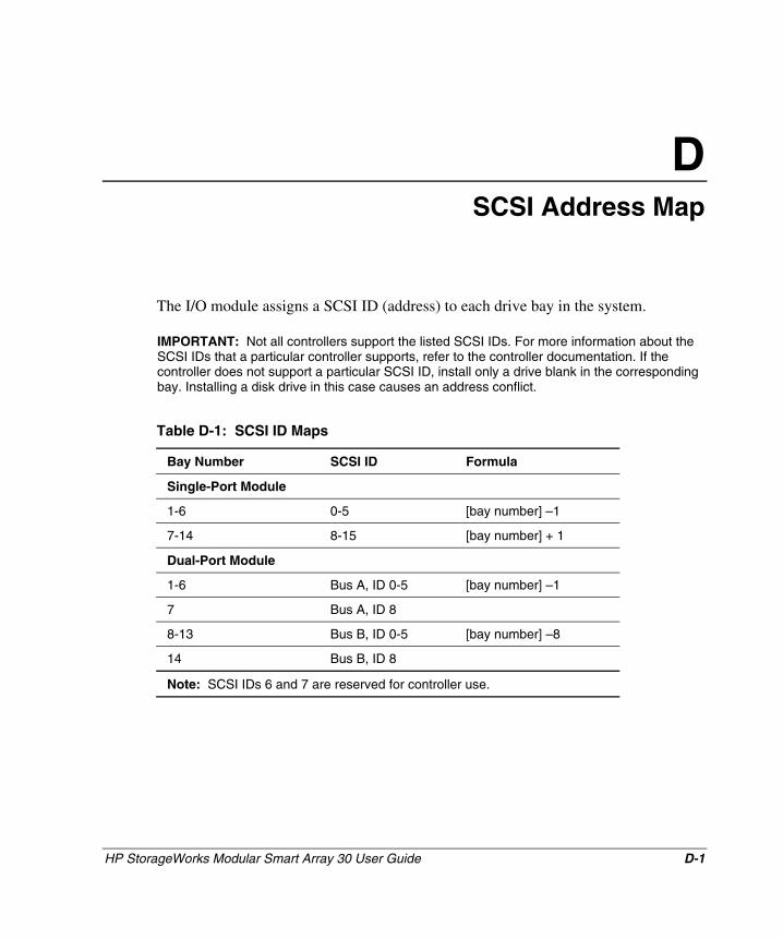
D SCSI Address Map
The I/O module assigns a SCSI ID (address) to each drive bay in the system.
IMPORTANT: Not all controllers support the listed SCSI IDs. For more information about the SCSI IDs that a particular controller supports, refer to the controller documentation. If the controller does not support a particular SCSI ID, install only a drive blank in the corresponding bay. Installing a disk drive in this case causes an address conflict.
Table D-1: SCSI ID Maps
Bay Number SCSI ID Formula
Single-Port Module
1-6 0-5 [bay number] – 1
7-14 8-15 [bay number] + 1
Dual-Port Module
1-6 Bus A, ID 0-5 [bay number] – 1
7 Bus A, ID 8
8-13 Bus B, ID 0-5 [bay number] – 8
14 Bus B, ID 8
Note: SCSI IDs 6 and 7 are reserved for controller use.
HP StorageWorks Modular Smart Array 30 User Guide Index-1
HP CONFIDENTIAL Writer: Susan Caesar File Name: x-index.doc
Codename: Northstar Part Number: 335900-002 Last Saved On: 10/3/03 11:43 AM
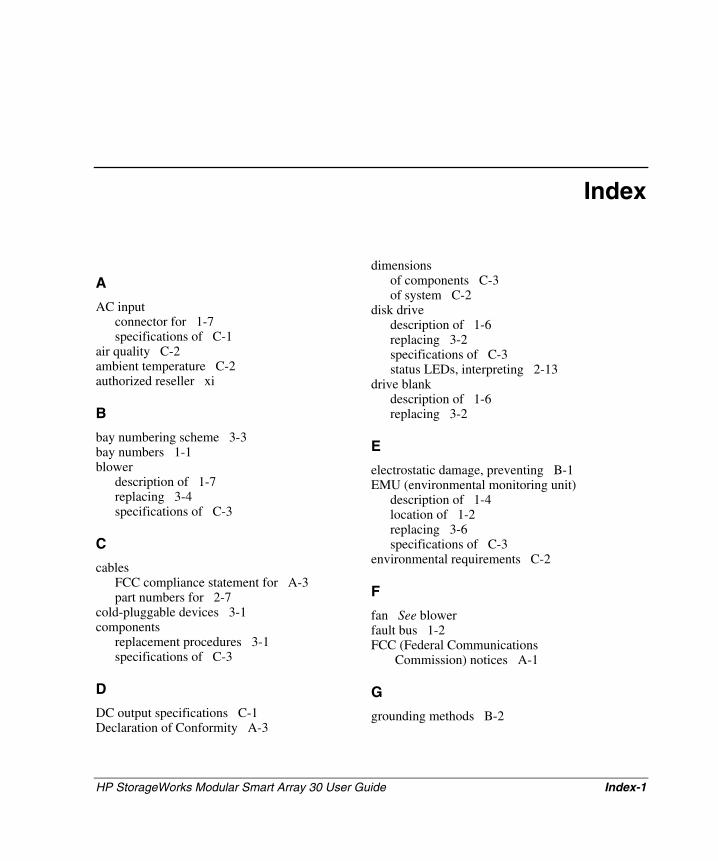
Index
A AC input
connector for 1-7 specifications of C-1
air quality C-2 ambient temperature C-2 authorized reseller xi
B bay numbering scheme 3-3 bay numbers 1-1 blower
description of 1-7 replacing 3-4 specifications of C-3
C cables
FCC compliance statement for A-3 part numbers for 2-7
cold-pluggable devices 3-1 components
replacement procedures 3-1 specifications of C-3
D DC output specifications C-1 Declaration of Conformity A-3
dimensions of components C-3 of system C-2
disk drive description of 1-6 replacing 3-2 specifications of C-3 status LEDs, interpreting 2-13
drive blank description of 1-6 replacing 3-2
E electrostatic damage, preventing B-1 EMU (environmental monitoring unit)
description of 1-4 location of 1-2 replacing 3-6 specifications of C-3
environmental requirements C-2
F fan See blower fault bus 1-2 FCC (Federal Communications
Commission) notices A-1
G grounding methods B-2
Index
Index-2 HP StorageWorks Modular Smart Array 30 User Guide
HP CONFIDENTIAL Writer: Susan Caesar File Name: x-index.doc
Codename: Northstar Part Number: 335900-002 Last Saved On: 10/3/03 11:43 AM
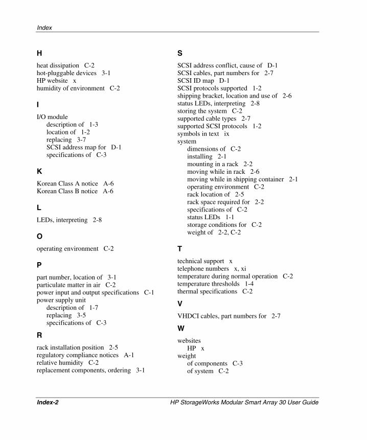
H heat dissipation C-2 hot-pluggable devices 3-1 HP website x humidity of environment C-2
I I/O module
description of 1-3 location of 1-2 replacing 3-7 SCSI address map for D-1 specifications of C-3
K Korean Class A notice A-6 Korean Class B notice A-6
L LEDs, interpreting 2-8
O operating environment C-2
P part number, location of 3-1 particulate matter in air C-2 power input and output specifications C-1 power supply unit
description of 1-7 replacing 3-5 specifications of C-3
R rack installation position 2-5 regulatory compliance notices A-1 relative humidity C-2 replacement components, ordering 3-1
S SCSI address conflict, cause of D-1 SCSI cables, part numbers for 2-7 SCSI ID map D-1 SCSI protocols supported 1-2 shipping bracket, location and use of 2-6 status LEDs, interpreting 2-8 storing the system C-2 supported cable types 2-7 supported SCSI protocols 1-2 symbols in text ix system
dimensions of C-2 installing 2-1 mounting in a rack 2-2 moving while in rack 2-6 moving while in shipping container 2-1 operating environment C-2 rack location of 2-5 rack space required for 2-2 specifications of C-2 status LEDs 1-1 storage conditions for C-2 weight of 2-2, C-2
T technical support x telephone numbers x, xi temperature during normal operation C-2 temperature thresholds 1-4 thermal specifications C-2
V VHDCI cables, part numbers for 2-7
W websites
HP x weight
of components C-3 of system C-2