Embed Size (px)
Citation preview
INNOVATIVEPILING
EQUIPMENT
HYDRAULIC PILING HAMMERS
EXCAVATOR MOUNTED VIBRATORS
EXCAVATOR MOUNTED DRILLS
QUIET, VIBRATIONLESSPUSH-PULL PILING
PILE EXTRACTION
SHEET PILE GUIDE FRAMES
SHEET PILE CAPPING SYSTEMS
CFA CLEANERS
PILE POINTS& SPLICERS
HANDLING / LIFTING
www.dcpuk.com
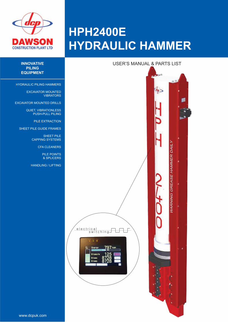
HPH2400EHYDRAULIC HAMMER
USER’S MANUAL & PARTS LIST

HAMMER SERIAL No: ................................................................................
HAMMER COMMISSION DATE: .............................................................
POWER PACK SERIAL No: .......................................................................
POWER PACK COMMISSION DATE: .....................................................
ENGINE TYPE: ............................................................................................
ENGINE SERIAL No: ..................................................................................
POWER PACK TYPE: .................................................................................
D.C.P. RESERVES THE RIGHT TO DISCONTINUE EQUIPMENT AT ANY TIME, OR CHANGE SPECIFICATIONS OR DESIGNS WITHOUT NOTICE OR INCURRING OBLIGATIONS
USER’S MANUAL
HPH 2400EHYDRAULIC HAMMER& POWER PACK SUMMARY
0.0 EC Declaration of Conformity
1.0 Introduction
1.1 Basic Safety Points - Basic Specification of HPH 2400 - Drawing - Lifting the HPH 2400 & Power Pack - Drawing1.2 Transportation and laying hammer down
2.0 How does the Hammer Work? Figure 1
3.0 Power Pack and Hammer Operation
3.1 Connecting the hydraulic hoses and control pendant3.2 Checking the power pack3.3 Starting the power pack3.3.1 Hydraulic oil warm-up procedure3.4 Using the hammer 3.4.1 Installing hammer on the pile 3.4.2 Bleeding air from the hammer hydraulic system3.4.3 Pile driving with the hammer 3.4.4 Cold running/overtravel 3.4.5 Refusal Figure 23.5 Using the hammer underwater3.6 Wider or special pile sections Figure 3, Figure 4 3.7 Preventive Maintenance Guideline Chart
4.0 Hammer Maintenance 4.1 Daily maintenance4.2 Planned 125 hour maintenance checks Figure 4.14.3 Planned 250 hour maintenance checks 4.3.1 Changing Disc Springs4.3.2 Other items 4.4 Planned 500 hour maintenance checks 4.5 Planned 1000 hour maintenance checks Hydraulic ram general assembly
5.0 Power Pack Maintenance 5.1 Power pack specifications 5.1.1 Basic specification 5.1.2 Lubrication specification 5.2 Daily maintenance checks 5.3 Planned maintenance checks 5.3.1 Every 125 hours 5.3.2 Every 250 hours 5.3.3 Every 500 hours 5.3.4 Every 1000 hours 5.4 Maintenance procedures 5.5 Setting procedures
6.0 Troubleshooting 6.1 Power pack engine will not start 6.2 Engine cuts out during running 6.3 Power pack does not generate any pressure 6.4 Power pack generates pressure but hammer does not run 6.5 Hammer will lift but not drop 6.6 Hammer runs erratically
7.0 Appendices 7.1 Hammer parts list 7.2 Accumulator parts list and instructions7.3 See John Deere service manual 7.4 Power pack parts list 7.4.1 Hydraulic circuit schematic7.4.2 Electrical circuit7.4.3 Engine Type 7.5 Tool kit parts list
8.0 Technical Specifications
8.1 Hammer Spec8.2 Bearing Capacity8.3 EMV Spec.8.4 Oil Hydraulic
CONTENTS

The responsible person:-
DAWSON CONSTRUCTION PLANT LIMITEDCHESNEY WOLD, BLEAK HALL
MILTON KEYNES MK6 1NEENGLAND
EC DECLARATION OF CONFORMITY
The above mentioned equipment conforms to the Machinery Directive 89/392/EEC(a) as amended by Council Directive 91/368/EEC(b), Council Directive 93/44/EEC(c) and Article 6 of Council Directive 93/68/EEC(d).
Signed for and on behalf of Dawson Construction Plant Limited: .............................................................................
Name: .............................................................................
Position: ............................................................................. Date: ............./............./.............
Description: ___________________________________
Type: ___________________________________
Serial Number: ___________________________________
HAMMER + POWER PACK
HPH2400E (Electric)
DAVID BROWN
MANAGING DIRECTOR

HPH2400E - DAWSON CONSTRUCTION PLANT
HPH2400E - DAWSON CONSTRUCTION PLANT
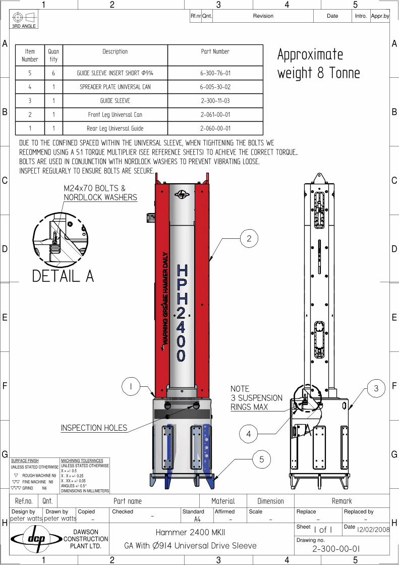
The D.C.P. Hydraulic Hammer has been designed and manufactured to meet the demands of today’s contractor. The hammer has many advantages over traditional piling hammers, including other hydraulic hammers:
. The hammer fits all British and most foreign single sheet piles as well as numerous ‘H’ piles using one set of legs and inserts. It will also fit pairs of sheet piles and open bent corners with the same configuration. This significantly improves productivity and reduces costs.. Hydraulic hammers are inherently efficient, typically 80-90% of the potential driving energy being transferred into the pile as opposed to 25-35% for diesel hammers.. Rapid blow rate. The hammer is double acting, not only giving high energy output, but increasing the speed of operation. This inevitably increases production and keeps the pile on the move.. Intelligent variable stroke controlled, between limits, at the touch of a button. This enables precise energy control which is very important when commencing piling or when coping with delicate operations. Full energy monitoring on screen.. Robust construction. The hammer has been designed with full knowledge of what is required of piling equipment. A quick look at the hammer sitting on a pile will confirm this.. With the hammer weighing only 6 tonnes, it lends itself to being used on long reach jobs where there are few economic alternatives.. Noise levels are considerably lower than that of diesel or air hammers.
Transmitted ground vibrations have been measured lower than that of a vibrator.
- Ear protection should be worn when in close proximity of the hammer.- Keep clear of the hammer and/or power pack when they are being lifted.- Avoid standing directly below the hammer when it is piling.- Adhere to maintenance requirements set out in this manual.- Lift equipment using lifting points specified only (see figures over).
- BEFORE operating hammer first time AND after each lay-down use inspection holes to ensure dolly is seated correctly in anvil before striking.- WHEN LAYING DOWN HAMMER, support top of hammer at higher level than bottom of hammer.- TRANSPORTATION, support top of hammer at higher level than bottom of hammer.
INTRODUCTION
1.1 Basic Safety Points
1.2 Transportation and laying down hammer
7
HPH2400E - DAWSON CONSTRUCTION PLANT
8
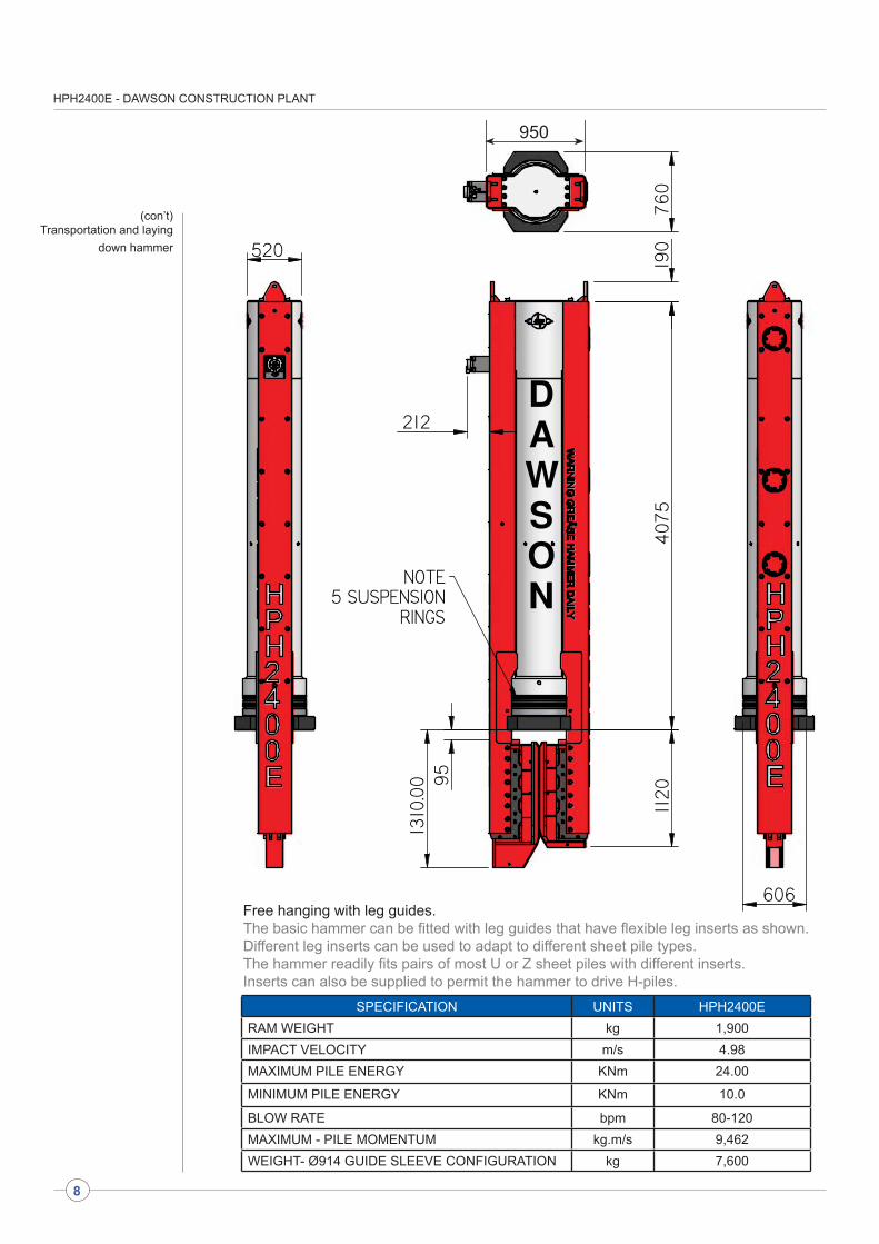
(con’t)Transportation and laying
down hammer
SPECIFICATION UNITS HPH2400ERAM WEIGHT kg 1,900IMPACT VELOCITY m/s 4.98MAXIMUM PILE ENERGY KNm 24.00
MINIMUM PILE ENERGY KNm 10.0
BLOW RATE bpm 80-120MAXIMUM - PILE MOMENTUM kg.m/s 9,462WEIGHT- Ø914 GUIDE SLEEVE CONFIGURATION kg 7,600
Free hanging with leg guides.The basic hammer can be fitted with leg guides that have flexible leg inserts as shown.Different leg inserts can be used to adapt to different sheet pile types.The hammer readily fits pairs of most U or Z sheet piles with different inserts.Inserts can also be supplied to permit the hammer to drive H-piles.
950
HPH2400E - DAWSON CONSTRUCTION PLANT
9
520
215
Ø1120
95
1233
4115
190
NOTE3 SUSPENSION
RINGS
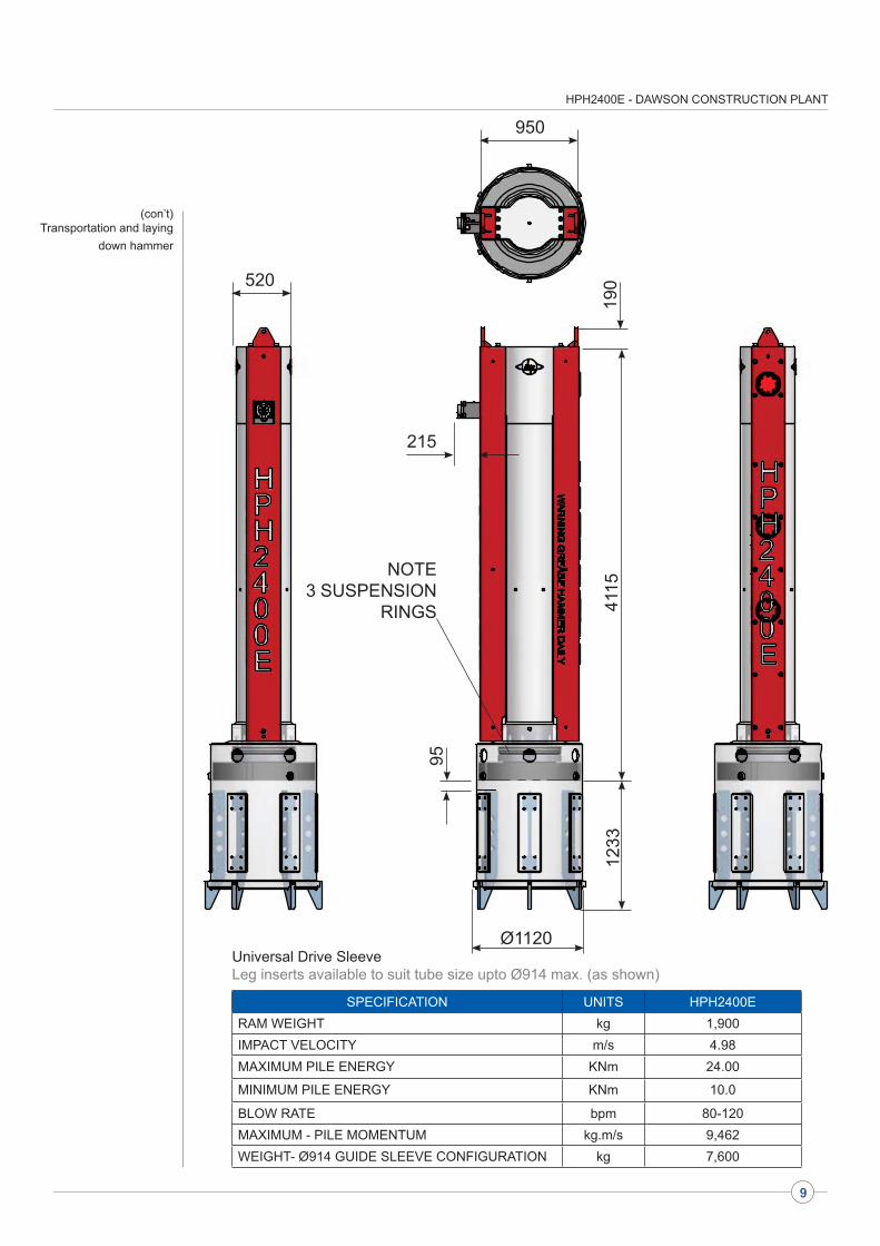
(con’t)Transportation and laying
down hammer
950
SPECIFICATION UNITS HPH2400ERAM WEIGHT kg 1,900IMPACT VELOCITY m/s 4.98MAXIMUM PILE ENERGY KNm 24.00
MINIMUM PILE ENERGY KNm 10.0
BLOW RATE bpm 80-120MAXIMUM - PILE MOMENTUM kg.m/s 9,462WEIGHT- Ø914 GUIDE SLEEVE CONFIGURATION kg 7,600
Universal Drive SleeveLeg inserts available to suit tube size upto Ø914 max. (as shown)
HPH2400E - DAWSON CONSTRUCTION PLANT
10
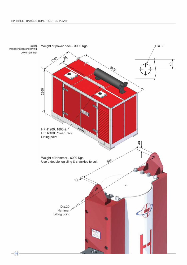
(con’t)Transportation and laying
down hammer
30
866
40
Dia.30Hammer
Lifting point
Weight of power pack - 3000 Kgs
Weight of Hammer - 6000 KgsUse a double leg sling & shackles to suit.
1340
2260
2850
HPH1200, 1800 & HPH2400 Power Pack Lifting point
25
40
Dia.30

HPH2400E - DAWSON CONSTRUCTION PLANT
11
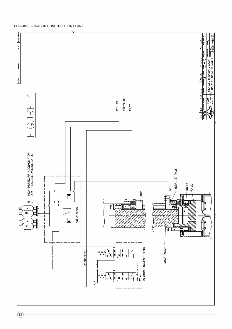
HOW DOES THE HAMMER WORK
INTERFACE SCREEN MOUNTED ON POWER PACK
The D.C.P. Hydraulic Hammer consists of a ‘drop weight’ driven up and down by ‘hydraulic rams’ inside the ‘casing.’ The hydraulic ram is double acting which means the drop weight is accelerated both on the upstroke and on the downstroke. This gives the hammer its very efficient energy output and high blow rate.
The oil supplied to the hydraulic ram comes from the power pack via a ‘control valve’ mounted inside the top of the hammer. This control valve switches the oil supply on or off at the upstroke side of the hydraulic ram i.e. oil supply ‘on’ lifts the drop weight and oil supply ‘off’ drops it.
Dawson Construction Plant has developed an industry leading, robust and simple, electronic control system that constantly monitors the drop weight position. This constant monitoring allows the switching timing on the main hydraulic spool to be trended to continually optimise hammer performance throughout varying piling conditions.
With constant drop weight position monitoring, the velocity of the drop weight is also known, therefore energy output can be accurately measured and is displayed to the operator on the powerpack interface screen. This information can be recorded direct to a laptop via a Dawson software interface, and can be saved in standard spreadsheet formats, giving a blow by blow account of every pile driven and a day to day productivity record.
The main screen displays bar graphs showing hammer stroke & hydraulic oil temperature.
An Off Pile indicator confirms when the hammer is securely seated on the pile, and allows piling to commence.
There are numerical read outs showing blows per minute, energy per blow and total blows. The lower reading shows blows in LAP cycle. (Measuring blows per increment). The units can be changed from imperial to metric.
The history screen provides information on the total number of start ups / total hours / total blows and total energy through out the life of the hammer.
HPH2400E - DAWSON CONSTRUCTION PLANT
12
HPH2400E - DAWSON CONSTRUCTION PLANT
(The power pack must be turned off at this time to enable correct installation of the hoses)
There are three hydraulic hoses running between the power pack and the hammer, viz:
1. Pressure line (1¼” BSP) carries the main high pressure oil supply to the hammer.2. Return line (1½” BSP) returns low pressure oil from the hammer to the power pack.3. Pilot Line (3/8” BSP)
The pressure/return hoses have the same specification. However, the return hose ends have larger fittings than the pressure hose to avoid possible confusion. Similarly, pilot hoses have different end types. The hoses should be left connected to the hammer at all times - this reduces the likelihood of oil contamination and reduces leakage problems. The hoses should be connected/ disconnected at the outlets of the power pack. All these connectors are of the ‘quick-release’ type. The hoses should be disconnected from the power pack when moving the power pack around to avoid straining the connectors.
Make sure that the connectors are thoroughly cleaned when making a connection
Having connected the hoses, next fit the hand control pendant connector block to the multi-pin outlet from the power pack. This is positioned below the instrumentation panel of the unit. Check that a clean connection is made and that no water is present in either half of the connection. The ‘power’ switch on the controller should be turned off.
Having connected the hydraulic hoses and hand control pendant, as described in section 3.1, next check fluid levels on the power pack. Check:
a. engine oil levelb. diesel fuel levelc. hydraulic oil level, and fill if required
Notes:-
1. The diesel fuel and hydraulic oil tanks have sight gauges on the side of the tanks.
2. The power pack will not run if the hydraulic oil level is too low.
3. The hammer will not run if the hydraulic oil temperature is too low. The auto warm-up routine must be used to pre-warm the oil. See section 3.3.1.
Prior to starting the power pack, check that the hand control pendant is turned ‘off.’ Set the throttle control lever to half of full throttle . Turn ‘on’ the battery isolator. Push the engine start push button until the engine starts.
Allow the engine to reach working temperature by running it at 1500 r.p.m. under zero load for 10-15 minutes. Check all gauges and diagnostic lights for correct function of unit (diagnostic lights should be off.)
Notes:-
1. If any of the following L.E.D.’s oil hot/cold/low are ‘on’ when the isolator switch is turned ‘on,’ the power pack will not start. Rectify problem immediately.2. If L.E.D. oil cold is on, the power pack will start but the pendant will be ‘dead’ until the hydraulic oil warm up procedure is carried out.
POWER PACK AND HAMMER OPERATION
3.1 Connecting the hydraulic hoses and
control pendant
3.2 Checking the power pack before
starting
3.3 Starting the power pack (see fig. 2)
13
HPH2400E - DAWSON CONSTRUCTION PLANT
14
If the hydraulic oil temperature is less than +25ºC, L.E.D. oil cold will be on and the oil will require warming prior to using the hammer.
The hand control pendant will be ‘dead’ for as long as L.E.D. oil cold is on.
To warm the oil:-
a) Run the engine at 1800 r.p.m.
b) Turn the ‘warm-up/run’ selector switch to ‘warm-up’. (The engine should go under load and the high pressure gauge should read approx. 200 bar).
c) Leave the pack in this condition until the L.E.D. goes off. (The engine should come off load at the same time the L.E.D. goes out and gauge return to zero bar).
d) Turn the ‘warm-up/run’ selector switch to ‘run’. The power pack is now ready for use.
The hammer must be sat correctly on the pile to avoid hammer or pile damage. The pile tops should be as level and square cut as possible. The hammer anvil must be in good condition.
Lift the hammer onto the pile(s) to be driven. Lower the hammer down until the handling slings lose their tension. At this point, the anvil should be seated correctly i.e. the rubber ring around the anvil should be compressed between the casing and the anvil. If it is not and there is a gap here, re-site the hammer.
Note: Before using the hammer (and particularly after transportation) check that the dolly is fitted correctly in the anvil. There are inspection holes at the bottom of the hammer casing to check this.
When running the hammer for the first time after initial connection to the power pack, there will be air in the hydraulic system. The hammer will ‘bleed’ this air automatically but the following procedure must be applied:-
a. Run the power pack at 2200 r.p.m.
b. Turn on the control pendant ‘power’ button.
c. Adjust the stroke height indicator to minimum using the ‘ ’ push button.
d. Set the ‘Auto/Man’ turn button to ‘Man.’
e. Hold the ‘start’ push button down for 2-3 seconds.
f. Repeat (e) three or four times until the hammer consistently gives one or two small blows each time. Providing the hammer does not ‘jump’ on the pile, hold the ‘start’ push button down, so that the hammer gives several consistent blows, on the next operation. (Approximately 120 blows per minute.) If the hammer ‘jumps’ on the pile, because the drop weight is hitting the top of the hammer casing, the hammer will stop automatically. To reset see section 3.4.4.
g. Commence the piling operation using the hammer as required.
3.3.1 Hydraulic Oil Warm-up Procedure
3.4 Using the hammer
3.4.1 Installing hammer on the pile
3.4.2. Bleeding air from the hammer
hydraulic system - only required when running
hammer after initial connection or following
a repair.
HPH2400E - DAWSON CONSTRUCTION PLANT
15
Having the hammer sited on the pile and removed air from the hydraulic system (if necessary) as described above, the hammer is ready for pile driving:-
a. Increase the power pack engine speed to 2200 r.p.m. (having followed - “Starting the power pack”section 3.3)
b. Turn the hand control pendant ‘power’ button on.
c. Adjust the ‘stroke height indicator’ on the side of the hammer to minimum stroke by pressing the ‘ ’ push button.
d. Set the ‘Auto/Man’ selector button to the required position:
‘Auto’ - hammer will continue running automatically when the ‘start’ push button is pressed once.‘Man’ - hammer will only run whilst the ‘start’ push button is held down.
e. Depress the ‘start’ push button as required by ‘Auto/Man.’
f. During operation the hammer stroke may be altered using the ‘ ‘ or ‘ ’ push buttons to adjust the stroke height indicator.
g. To stop the hammer whilst it is running on ‘Auto,’ turn the ‘Auto/Man’ selector to ‘Man’ or turn the ‘power’ selector off. It is good practice to start piling with the hammer set on minimum stroke, this limits unnecessary damage to both the hammer and the pile when the pile can be driven easily. The stroke may then be adjusted to suit the changing driving resistance.
On certain piling jobs, it may be possible to start driving on pairs of sheet piles, changing over onto a single sheet pile as the driving resistance increases (this will give maximum productivity.)
3.4.3 Pile driving with the hammer
The hammer ‘jumps’ on the pile top when trying to achieve full stroke if the hydraulic system is ‘cold.’ If this happens, the hammer will stop automatically. (Thus preventing internal damage to the unit.) The power pack will continue to run and the ‘pressure’ gauge will read approximately 240 bar.
In order to reset the hammer, turn off the ‘power’ selector on the hand control pendant and stop the power pack. Allow the engine to stop for approximately 10 seconds then restart the unit. Reduce the stroke of the hammer to minimum. Run the hammer at this lower setting until the oil is warm enough to allow correct full stroke setting. If reducing the stroke does not cure the problem, warm the hydraulic oil as described in section 3.3.1. If the hammer overtravels again, refer to the Troubleshooting section 6.0.
THE HAMMER WILL NOT RUN IF IT IS NOT ALLOWED TO RESET CORRECTLY
! Piling must stop with this hammer when the rate of driving reaches 10 blows per 25mm !Continued use will result in hammer and/or pile damage
3.4.4 Cold running/overtravel
3.4.5 Refusal
HPH2400E - DAWSON CONSTRUCTION PLANT
16
Return Pressure
Hammer Pressure
Oil Hot
Oil Cold
Oil Low
Man/Auto
Emergency Stop
Warm Run
Lower
Raise
Pendant Panel
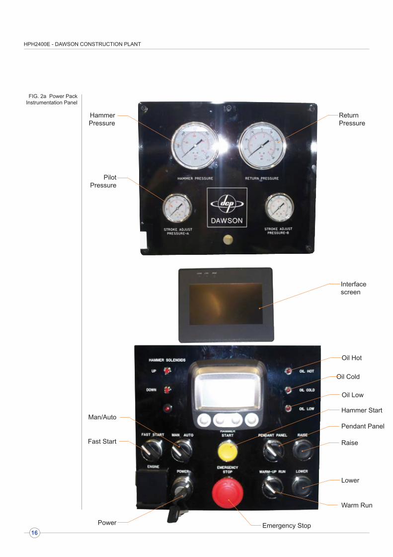
FIG. 2a Power Pack Instrumentation Panel
PilotPressure
Power
Fast Start
Hammer Start
Interface screen
HPH2400E - DAWSON CONSTRUCTION PLANT
FIG. 2a Power Pack Instrumentation Panel
- Interface screen operation
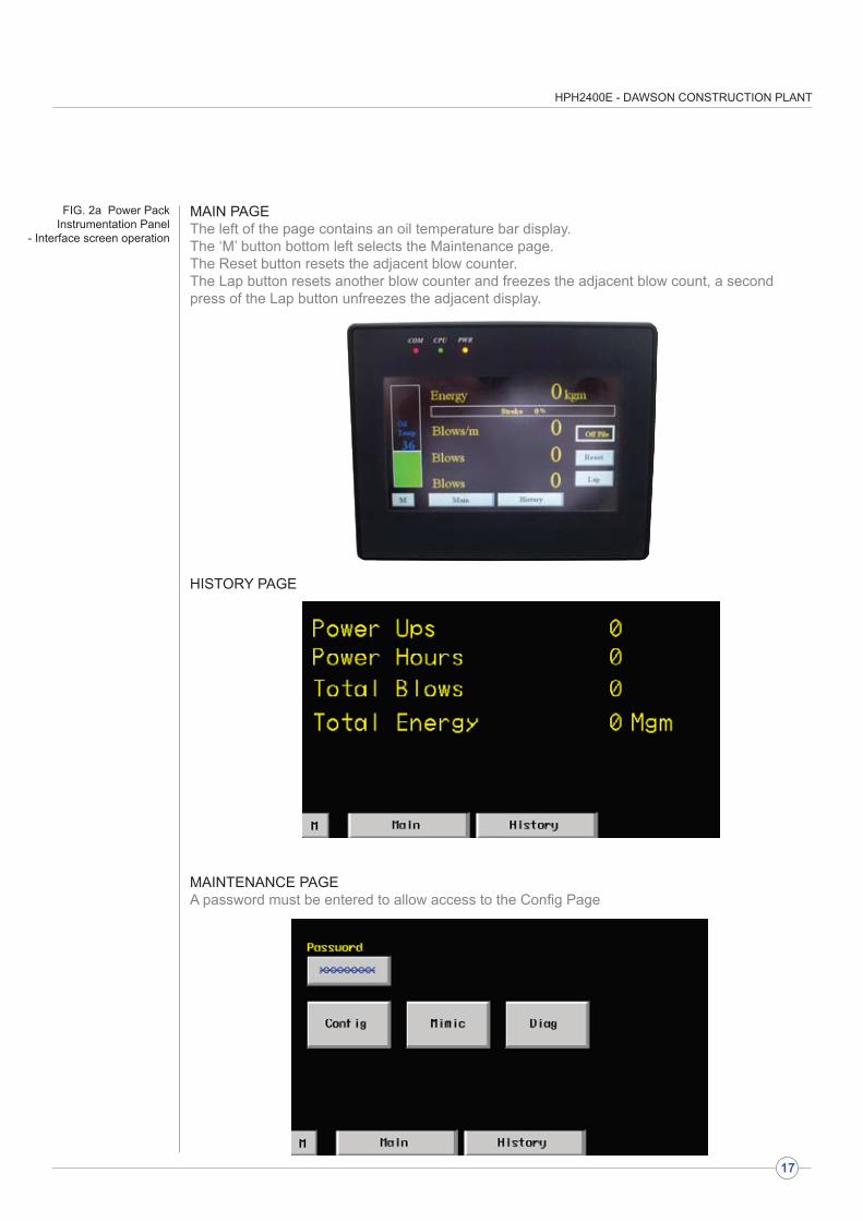
MAIN PAGEThe left of the page contains an oil temperature bar display. The ‘M’ button bottom left selects the Maintenance page. The Reset button resets the adjacent blow counter. The Lap button resets another blow counter and freezes the adjacent blow count, a second press of the Lap button unfreezes the adjacent display.
HISTORY PAGE
MAINTENANCE PAGEA password must be entered to allow access to the Config Page
17
HPH2400E - DAWSON CONSTRUCTION PLANT
18
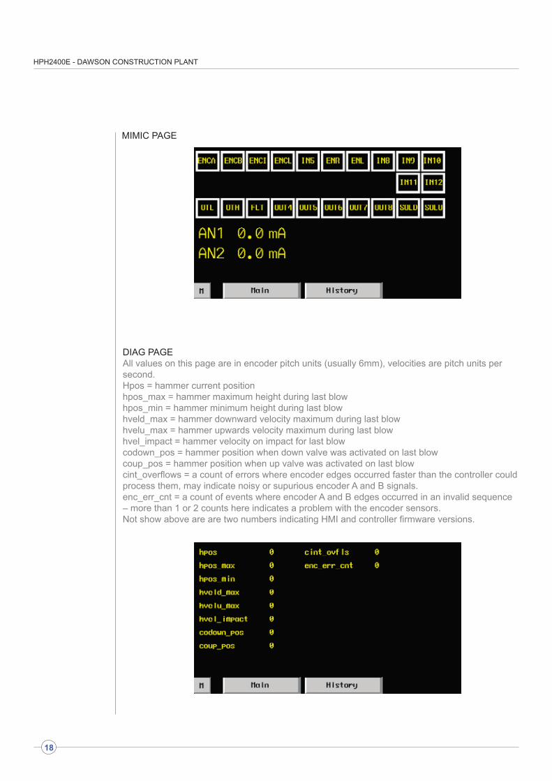
MIMIC PAGE
DIAG PAGEAll values on this page are in encoder pitch units (usually 6mm), velocities are pitch units persecond.Hpos = hammer current positionhpos_max = hammer maximum height during last blowhpos_min = hammer minimum height during last blowhveld_max = hammer downward velocity maximum during last blowhvelu_max = hammer upwards velocity maximum during last blowhvel_impact = hammer velocity on impact for last blowcodown_pos = hammer position when down valve was activated on last blowcoup_pos = hammer position when up valve was activated on last blowcint_overflows = a count of errors where encoder edges occurred faster than the controller couldprocess them, may indicate noisy or supurious encoder A and B signals.enc_err_cnt = a count of events where encoder A and B edges occurred in an invalid sequence – more than 1 or 2 counts here indicates a problem with the encoder sensors.Not show above are are two numbers indicating HMI and controller firmware versions.
HPH2400E - DAWSON CONSTRUCTION PLANT
19
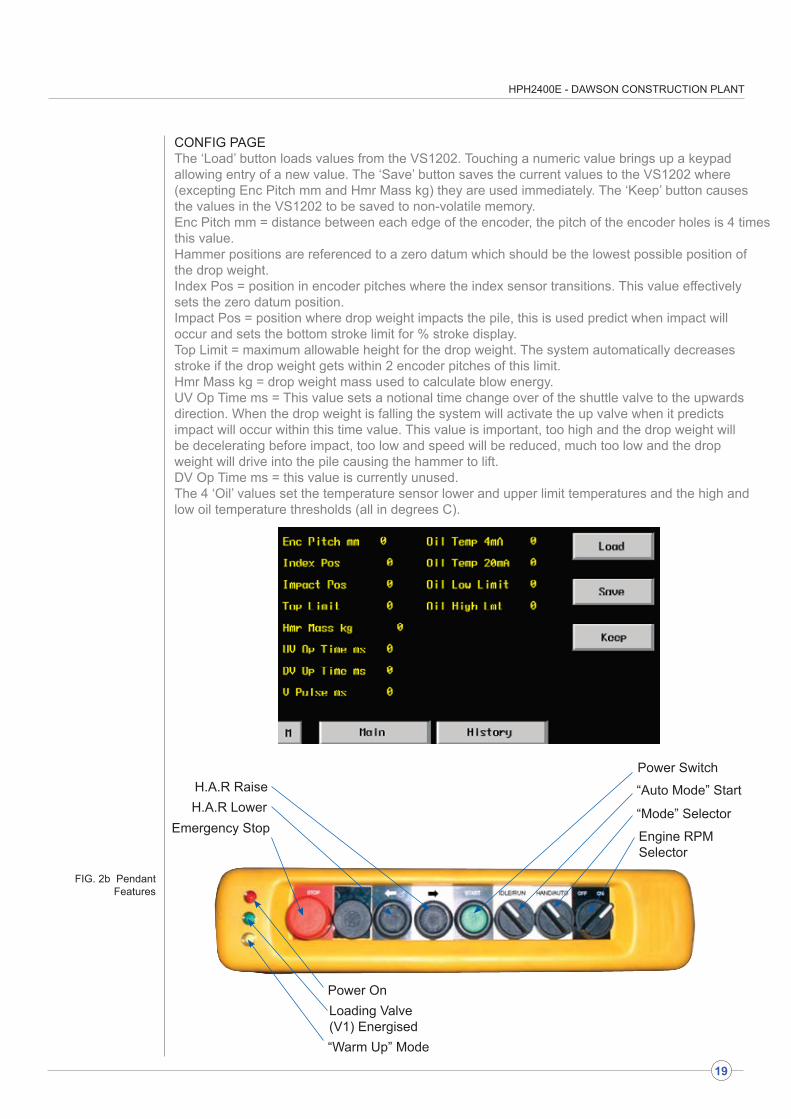
Power Switch
“Mode” Selector
Engine RPMSelector
“Auto Mode” StartH.A.R RaiseH.A.R Lower
Emergency Stop
“Warm Up” Mode
Loading Valve(V1) Energised
Power On
FIG. 2b Pendant Features
CONFIG PAGEThe ‘Load’ button loads values from the VS1202. Touching a numeric value brings up a keypadallowing entry of a new value. The ‘Save’ button saves the current values to the VS1202 where(excepting Enc Pitch mm and Hmr Mass kg) they are used immediately. The ‘Keep’ button causesthe values in the VS1202 to be saved to non-volatile memory.Enc Pitch mm = distance between each edge of the encoder, the pitch of the encoder holes is 4 timesthis value.Hammer positions are referenced to a zero datum which should be the lowest possible position ofthe drop weight.Index Pos = position in encoder pitches where the index sensor transitions. This value effectivelysets the zero datum position.Impact Pos = position where drop weight impacts the pile, this is used predict when impact willoccur and sets the bottom stroke limit for % stroke display.Top Limit = maximum allowable height for the drop weight. The system automatically decreasesstroke if the drop weight gets within 2 encoder pitches of this limit.Hmr Mass kg = drop weight mass used to calculate blow energy.UV Op Time ms = This value sets a notional time change over of the shuttle valve to the upwardsdirection. When the drop weight is falling the system will activate the up valve when it predictsimpact will occur within this time value. This value is important, too high and the drop weight willbe decelerating before impact, too low and speed will be reduced, much too low and the dropweight will drive into the pile causing the hammer to lift.DV Op Time ms = this value is currently unused.The 4 ‘Oil’ values set the temperature sensor lower and upper limit temperatures and the high andlow oil temperature thresholds (all in degrees C).
HPH2400E - DAWSON CONSTRUCTION PLANT
20
It is possible to drive piles with this hammer underwater. However, the hammer must be prepared correctly in order to do so - it can not be used underwater in standard format.
The work involved is briefly as follows:-
a) The stroke adjuster ‘slot’ in the leg guide must be sealed with a cover.
b) The insides of the hammer should be suitably greased to minimise the effects of corrosion.
c) The gaps between hammer casing, leg guides and top cover must be sealed with silicone mastic.
d) The inspection holes near the bottom of the hammer casing must be plugged.
e) A threaded compressed airline port must be added in the bottom end of the hammer casing or leg guide.
f) The hammer must be run in conjunction with a 35/70 c.f.m. (100 psi) air compressor.
g) The hammer grease nipples must be greased after every pile drive to ensure ample lubrication.
NOTE: FOR DETAILED ASSISTANCE WITH THIS TYPE OF WORK PLEASE CONTACT THE MANUFACTURER.
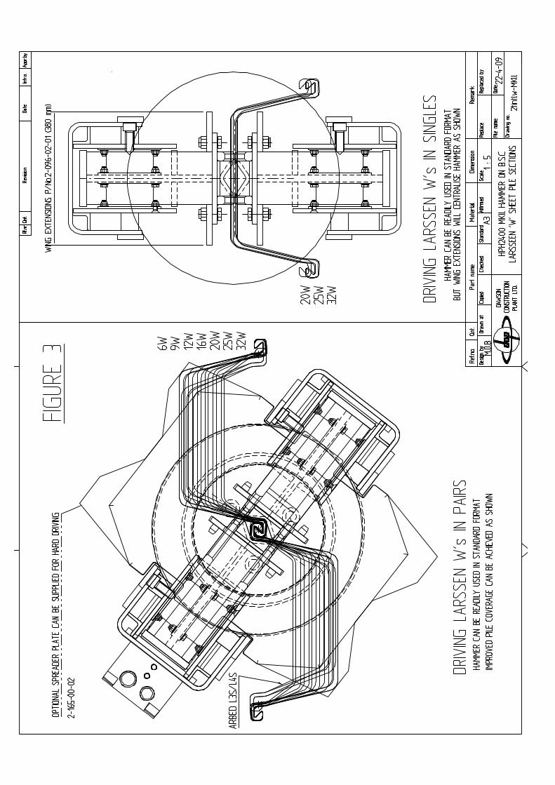
The HPH 2400 hammer in standard format will drive a considerable range of steel piles. In some applications, however, where sheet piles are particularly wide or perhaps boxed together it is possible to use simple leg insert modifications and/or spreader plates to give improved pile coverage reducing pile head stress and improving productivity rates.
The standard leg inserts can have “wing extensions” bolted on to correctly centralise the hammer on a single sheet pile. Then either a special anvil can be used to give wider coverage, or, by dropping the inserts to a lower set of location holes, a ‘spreader plate’ can be added below the standard anvil to give improved pile coverage. This is a tried and tested technique (see figure 3).
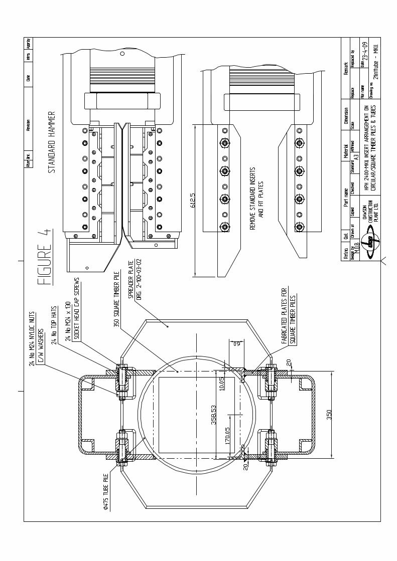
With tubular piles, for example, the standard inserts can be removed and in place some simple bolt on plates added to centralise the hammer on the tube (see figure 4). A further refinement, if necessary, is to weld a ring onto the underside of the anvil to give correct location on the tube.
PLEASE CONTACT THE MANUFACTURER IF YOU HAVE A SPECIFIC PILE DRIVING PROBLEM - IT MAY HAVE BEEN DONE BEFORE!
3.5 Using the hammer underwater
3.6 Wider or special pile sections
DA
ILY
OR
REF
UEL
LIN
GEV
ERY
125
HO
UR
SEV
ERY
250
HO
UR
SEV
ERY
500
HO
UR
SEV
ERY
1000
HO
UR
SEV
ERY
2000
HO
UR
SENGINE
CH
EC
K:
. O
IL L
EV
EL
. C
OO
LAN
T LE
VE
L .
FA
N -
INS
PE
CTI
ON
.
DR
IVE
BE
LT -
INS
PE
CT
. F
UE
L W
ATE
R T
RA
P - D
RA
IN
CH
AN
GE
: .
LU
BE
OIL
.
LU
BE
FIL
TER
CH
EC
K:
. A
IR C
LEA
NE
R
. IN
TAK
E S
YS
TEM
. C
HA
RG
E A
IR C
OO
LER
CH
AN
GE
: .
FU
EL
FILT
ER
CH
EC
K:
. A
NTI
FR
EE
ZE
AD
JUS
T:
. V
ALV
E L
AS
H C
LEA
RA
NC
E
CH
EC
K:
. F
AN
HU
B
. B
ELT
TE
NS
ION
ER
BE
AR
ING
.
BE
LT T
EN
SIO
N
CH
AN
GE
: .
AN
TI F
RE
EZE
CH
EC
K:
. D
AM
PE
R
POWER PACK
CH
EC
K:
. H
YD
RA
ULI
C O
IL L
EV
EL
. A
IR IN
LET/
OU
TLE
TS F
RE
E
FR
OM
OB
STR
UC
TIO
N.
CO
ND
ITIO
N O
F LI
FTIN
G
P
OIN
TS &
SLI
NG
S/
S
HA
CK
LES
. T
ES
T D
IAG
NO
STI
C L
ED
S.
INS
PE
CT
GA
UG
ES
. C
ON
DIT
ION
OF
QU
ICK
RE
LEA
SE
CO
UP
LIN
GS
CH
EC
K:
. F
OR
HY
DR
AU
LIC
OIL
LE
AK
S
&
RE
CTI
FY.
CO
ND
ITIO
N O
F H
OS
ES
. T
IGH
TNE
SS
OF
FAS
TEN
ER
S.
CO
ND
ITIO
N O
F PA
INTW
OR
K.
BAT
TER
Y W
ATE
R L
EV
EL
. F
UN
CTI
ON
OF
PE
ND
AN
T &
CO
ND
ITIO
N O
F C
AB
LE
CH
EC
K:
. B
ATTE
RY
CH
AR
GIN
G
CH
AN
GE
:.
HY
DR
AU
LIC
OIL
/FU
EL
F
ILLE
R F
ILTE
RS
CH
EC
K:
. P
RE
SS
UR
E O
UTP
UT
OF
P
UM
P.
FLO
W O
UTP
UT
OF
PU
MP
CH
AN
GE
:.
PR
ES
SU
RE
/RE
TUR
N
H
YD
RA
ULI
C F
ILTE
RS
CH
EC
K:
. C
ON
DIT
ION
OF
WIR
ING
. D
RIV
E C
OU
PLI
NG
FO
R W
EA
R.
CO
ND
ITIO
N O
F E
XH
AU
ST
CH
AN
GE
:.
HY
DR
AU
LIC
OIL
AN
D C
LEA
N
O
UT
SY
STE
M
HAMMER
CH
EC
K:
. A
LL E
XTE
RN
AL
FAS
TEN
ER
S
F
OR
TIG
HTN
ES
S.
DO
LLY
CO
ND
ITIO
N
.
S
US
PE
NS
ION
BLO
CK
&
S
US
PE
NS
ION
RIN
G
C
ON
DIT
ION
. L
IFTI
NG
PO
INT
CO
ND
ITIO
N.
SE
RV
ICE
AB
ILIT
Y O
F
SLI
NG
S/S
HA
CK
LES
MU
ST:
. G
RE
AS
E H
AM
ME
R
F
RE
QU
EN
TLY
CH
EC
K:
. T
IGH
TNE
SS
OF
ALL
HO
SE
S,
F
ITTI
NG
S A
ND
FA
STE
NE
RS
INS
IDE
HA
MM
ER
. C
ON
DIT
ION
OF
BO
TH
SE
NS
OR
S.
WE
AR
LE
VE
L O
N L
EG
INS
ER
TS
CH
EC
K:
. .
AC
CU
MU
LATO
R N
ITR
OG
EN
PR
EC
HA
RG
E P
RE
SS
UR
ES
. H
AM
ME
R F
ILTE
R
CH
AN
GE
:.
RE
SIL
IEN
T W
AS
HE
RS
BE
TWE
EN
DR
OP
WE
IGH
T &
HY
DR
AU
LIC
RA
M O
N H
PH
240
0 O
NLY
CH
EC
K:
. T
IGH
TNE
SS
OF
A
CC
UM
ULA
TOR
S.
CO
ND
ITIO
N O
F M
AIN
FE
ED
HO
SE
S T
O H
AM
ME
R
CH
AN
GE
:.
RE
SIL
IEN
T W
AS
HE
RS
BE
TWE
EN
DR
OP
WE
IGH
T
AN
D H
YD
RA
ULI
C R
AM
CH
EC
K:
. P
LAY
IN M
AIN
RA
M
A
NC
HO
RA
GE
AS
SE
MB
LY.
CO
ND
ITIO
N O
F A
NV
IL.
PLA
Y B
ETW
EE
N D
RO
P
WE
IGH
T A
ND
CA
SIN
G B
OR
E
TES
T R
UN
ON
PIL
E 1
5 M
INU
TES
BE
FOR
E A
ND
AFT
ER
C
HE
CK
ING
TES
T R
UN
ON
PIL
E 1
5 M
INU
TES
BE
FOR
E A
ND
AFT
ER
C
HE
CK
ING
TES
T R
UN
ON
PIL
E 3
0 M
INU
TES
B
EFO
RE
AN
D A
FTE
R C
HE
CK
ING
TES
T R
UN
ON
PIL
E 3
0 M
INU
TES
B
EFO
RE
AN
D A
FTE
R C
HE
CK
ING
TES
T R
UN
ON
PIL
E 3
0 M
INU
TES
B
EFO
RE
AN
D A
FTE
R C
HE
CK
ING
3.7
PREV
ENTA
TIVE
MA
INTE
NA
NC
E G
UID
ELIN
ES F
OR
HPH
120
0 &
240
0 H
YDR
AU
LC H
AM
MER
S, A
ND
DIE
SEL
ENG
INED
PO
WER
PA
CK
S
(FO
R F
ULL
DE
TAIL
S S
EE
SE
CTI
ON
S 4
AN
D 5
IN T
HE
HA
MM
ER
MA
NU
AL
AN
D T
HE
CU
MM
INS
SE
RV
ICE
MA
NU
AL)
HPH2400E - DAWSON CONSTRUCTION PLANT
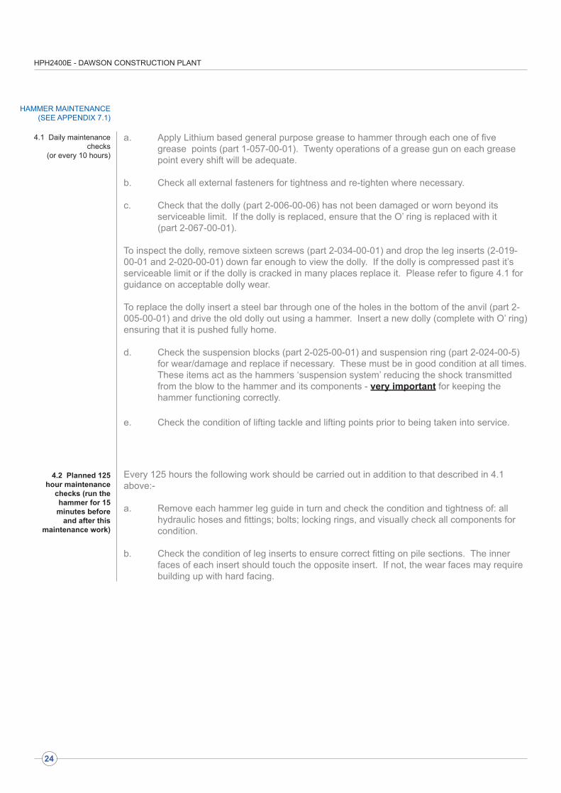
a. Apply Lithium based general purpose grease to hammer through each one of five grease points (part 1-057-00-01). Twenty operations of a grease gun on each grease point every shift will be adequate.
b. Check all external fasteners for tightness and re-tighten where necessary.
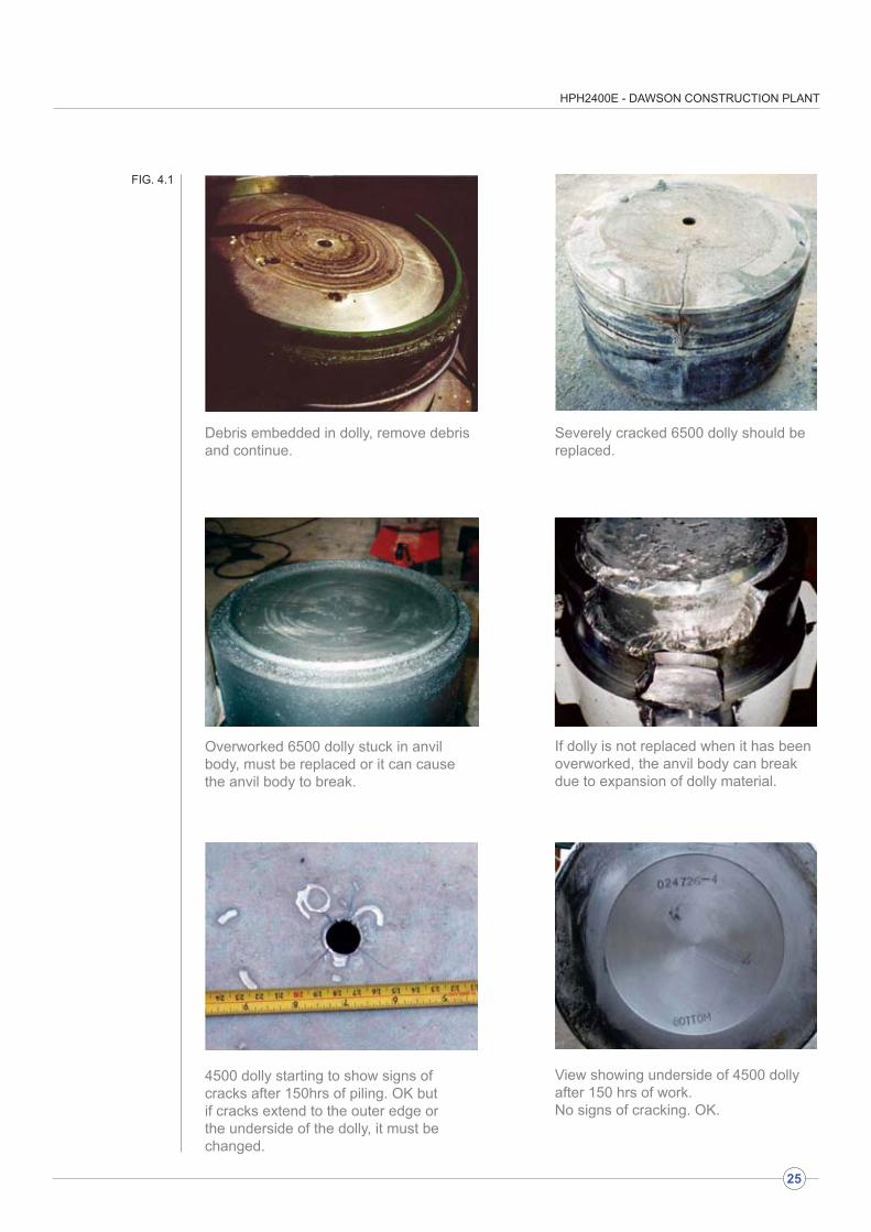
c. Check that the dolly (part 2-006-00-06) has not been damaged or worn beyond its serviceable limit. If the dolly is replaced, ensure that the O’ ring is replaced with it (part 2-067-00-01). To inspect the dolly, remove sixteen screws (part 2-034-00-01) and drop the leg inserts (2-019-00-01 and 2-020-00-01) down far enough to view the dolly. If the dolly is compressed past it’s serviceable limit or if the dolly is cracked in many places replace it. Please refer to figure 4.1 for guidance on acceptable dolly wear.
To replace the dolly insert a steel bar through one of the holes in the bottom of the anvil (part 2-005-00-01) and drive the old dolly out using a hammer. Insert a new dolly (complete with O’ ring) ensuring that it is pushed fully home.
d. Check the suspension blocks (part 2-025-00-01) and suspension ring (part 2-024-00-5) for wear/damage and replace if necessary. These must be in good condition at all times. These items act as the hammers ‘suspension system’ reducing the shock transmitted from the blow to the hammer and its components - very important for keeping the hammer functioning correctly.
e. Check the condition of lifting tackle and lifting points prior to being taken into service.
Every 125 hours the following work should be carried out in addition to that described in 4.1 above:-
a. Remove each hammer leg guide in turn and check the condition and tightness of: all hydraulic hoses and fittings; bolts; locking rings, and visually check all components for condition.
b. Check the condition of leg inserts to ensure correct fitting on pile sections. The inner faces of each insert should touch the opposite insert. If not, the wear faces may require building up with hard facing.
HAMMER MAINTENANCE(SEE APPENDIX 7.1)
4.1 Daily maintenance checks
(or every 10 hours)
4.2 Planned 125 hour maintenance
checks (run the hammer for 15 minutes before
and after this maintenance work)
24
HPH2400E - DAWSON CONSTRUCTION PLANT
Debris embedded in dolly, remove debris and continue.
Severely cracked 6500 dolly should be replaced.
Overworked 6500 dolly stuck in anvil body, must be replaced or it can cause the anvil body to break.
If dolly is not replaced when it has been overworked, the anvil body can break due to expansion of dolly material.
4500 dolly starting to show signs of cracks after 150hrs of piling. OK but if cracks extend to the outer edge or the underside of the dolly, it must be changed.
View showing underside of 4500 dolly after 150 hrs of work.No signs of cracking. OK.
FIG. 4.1
25
HPH2400E - DAWSON CONSTRUCTION PLANT
26
12
JIHGF
34
56
EDCBA
12
34
56
78
910
1112
JIHGF
78
910
EDC
1112
BA
Cop
ied
Des
ign
byD
raw
n by
Che
cked
Sta
nda
rdS
cale
Aff
irmed
Dra
win
g no
.
She
et
Rep
lace
Dat
e
Rep
lace
d by
Qnt
.R
f.nr
Re
visi
onA
ppr.
byD
ate
Intr
o.
DAW
SON
CO
NST
RU
CTI
ON
PLAN
T LT
D.
3RD
AN
GLE
ROUG
H M
ACHI
NE N
9
FINE
MAC
HINE
N8
GRI
ND
N6
UNLE
SS S
TATE
D O
THER
WIS
ESU
RFAC
E FI
NISH
X . X
= +
/- 0.
25
ANG
LES
+/- 0
.5°
MAC
HINI
NG T
OLE
RANC
ESUN
LESS
STA
TED
OTH
ERW
ISE
X . X
X =
+/- 0
.05
DIM
ENSI
ONS
IN M
ILLI
MET
ERS
X =
+/- 0
.5
83
DIM
A
HPH2400E - DAWSON CONSTRUCTION PLANT
27
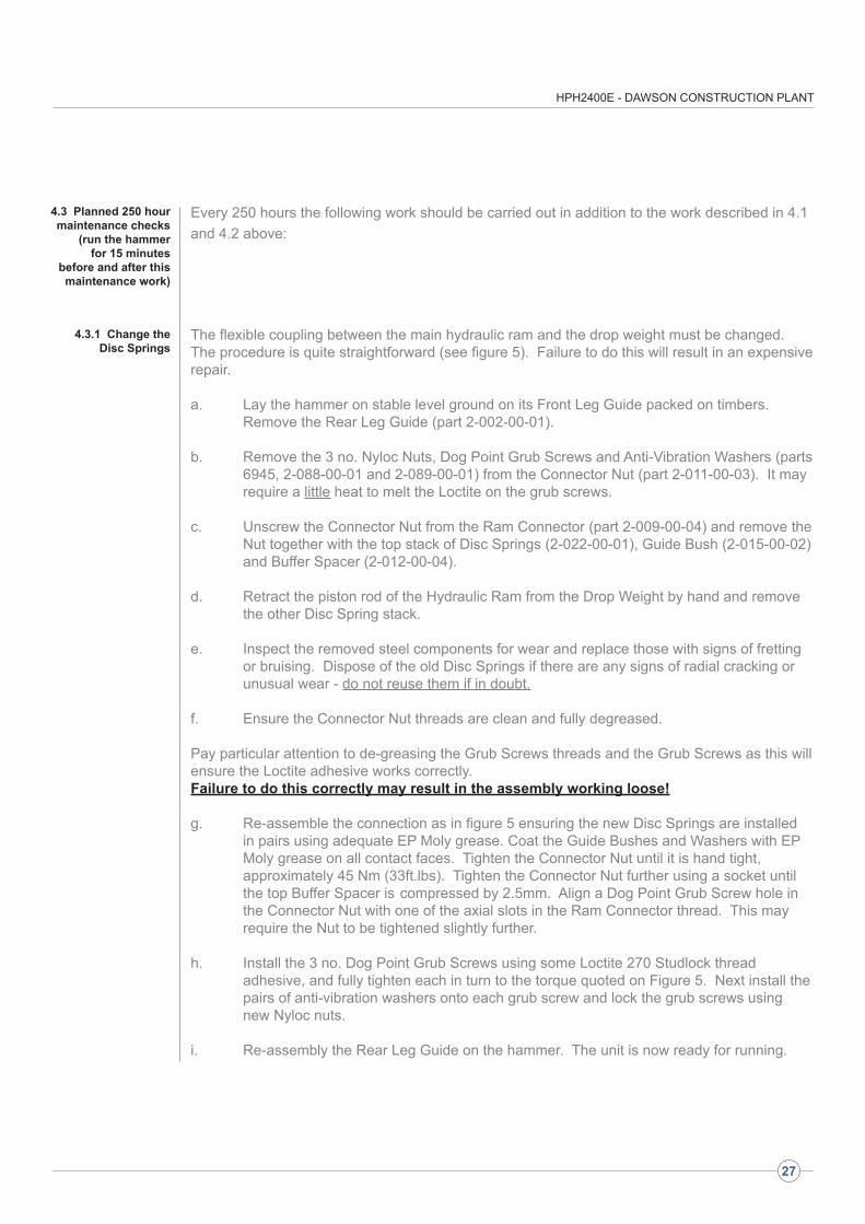
Every 250 hours the following work should be carried out in addition to the work described in 4.1 and 4.2 above:
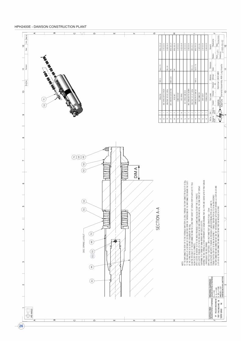
The flexible coupling between the main hydraulic ram and the drop weight must be changed. The procedure is quite straightforward (see figure 5). Failure to do this will result in an expensive repair.
a. Lay the hammer on stable level ground on its Front Leg Guide packed on timbers. Remove the Rear Leg Guide (part 2-002-00-01).
b. Remove the 3 no. Nyloc Nuts, Dog Point Grub Screws and Anti-Vibration Washers (parts 6945, 2-088-00-01 and 2-089-00-01) from the Connector Nut (part 2-011-00-03). It may require a little heat to melt the Loctite on the grub screws.
c. Unscrew the Connector Nut from the Ram Connector (part 2-009-00-04) and remove the Nut together with the top stack of Disc Springs (2-022-00-01), Guide Bush (2-015-00-02) and Buffer Spacer (2-012-00-04).
d. Retract the piston rod of the Hydraulic Ram from the Drop Weight by hand and remove the other Disc Spring stack.
e. Inspect the removed steel components for wear and replace those with signs of fretting or bruising. Dispose of the old Disc Springs if there are any signs of radial cracking or unusual wear - do not reuse them if in doubt.
f. Ensure the Connector Nut threads are clean and fully degreased.
Pay particular attention to de-greasing the Grub Screws threads and the Grub Screws as this will ensure the Loctite adhesive works correctly. Failure to do this correctly may result in the assembly working loose!
g. Re-assemble the connection as in figure 5 ensuring the new Disc Springs are installed in pairs using adequate EP Moly grease. Coat the Guide Bushes and Washers with EP Moly grease on all contact faces. Tighten the Connector Nut until it is hand tight, approximately 45 Nm (33ft.lbs). Tighten the Connector Nut further using a socket until the top Buffer Spacer is compressed by 2.5mm. Align a Dog Point Grub Screw hole in the Connector Nut with one of the axial slots in the Ram Connector thread. This may require the Nut to be tightened slightly further.
h. Install the 3 no. Dog Point Grub Screws using some Loctite 270 Studlock thread adhesive, and fully tighten each in turn to the torque quoted on Figure 5. Next install the pairs of anti-vibration washers onto each grub screw and lock the grub screws using new Nyloc nuts.
i. Re-assembly the Rear Leg Guide on the hammer. The unit is now ready for running.
4.3 Planned 250 hour maintenance checks
(run the hammer for 15 minutes
before and after this maintenance work)
4.3.1 Change the Disc Springs
HPH2400E - DAWSON CONSTRUCTION PLANT
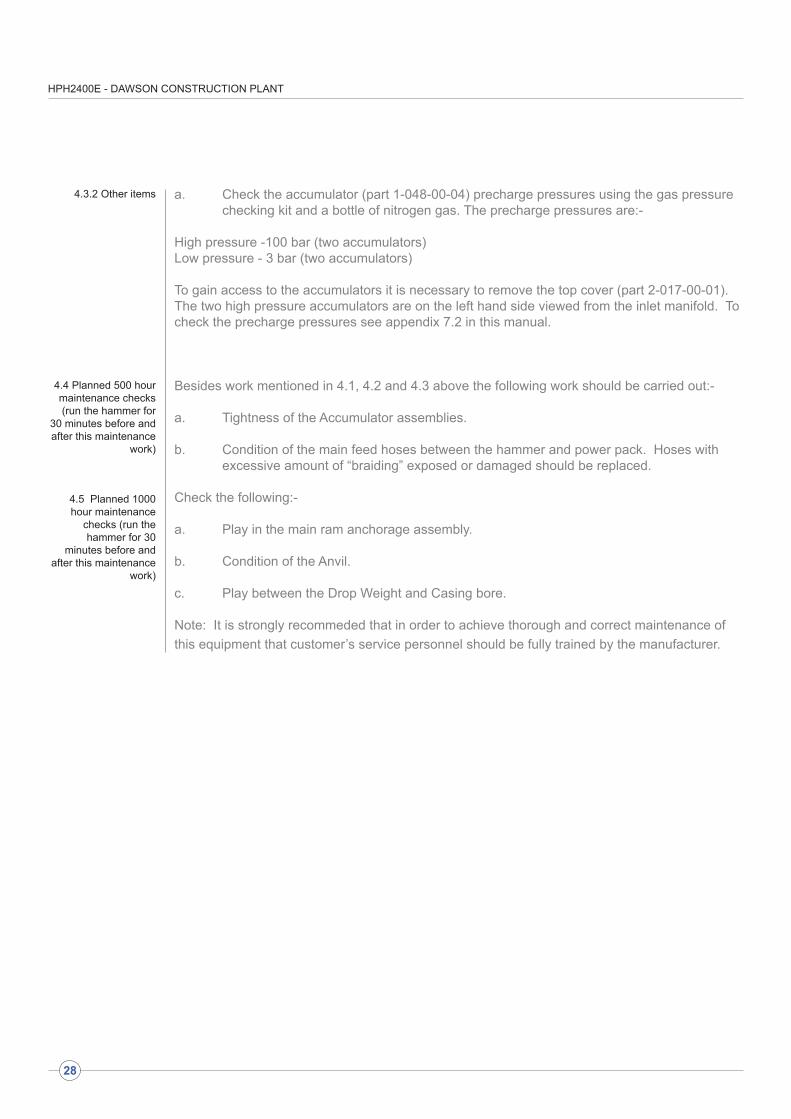
a. Check the accumulator (part 1-048-00-04) precharge pressures using the gas pressure checking kit and a bottle of nitrogen gas. The precharge pressures are:-
High pressure -100 bar (two accumulators)Low pressure - 3 bar (two accumulators)
To gain access to the accumulators it is necessary to remove the top cover (part 2-017-00-01). The two high pressure accumulators are on the left hand side viewed from the inlet manifold. To check the precharge pressures see appendix 7.2 in this manual.
Besides work mentioned in 4.1, 4.2 and 4.3 above the following work should be carried out:-
a. Tightness of the Accumulator assemblies.
b. Condition of the main feed hoses between the hammer and power pack. Hoses with excessive amount of “braiding” exposed or damaged should be replaced.
Check the following:-
a. Play in the main ram anchorage assembly.
b. Condition of the Anvil.
c. Play between the Drop Weight and Casing bore.
Note: It is strongly recommeded that in order to achieve thorough and correct maintenance of this equipment that customer’s service personnel should be fully trained by the manufacturer.
4.3.2 Other items
4.4 Planned 500 hour maintenance checks (run the hammer for
30 minutes before and after this maintenance
work)
4.5 Planned 1000 hour maintenance
checks (run the hammer for 30
minutes before and after this maintenance
work)
28
HPH2400E - DAWSON CONSTRUCTION PLANT
29
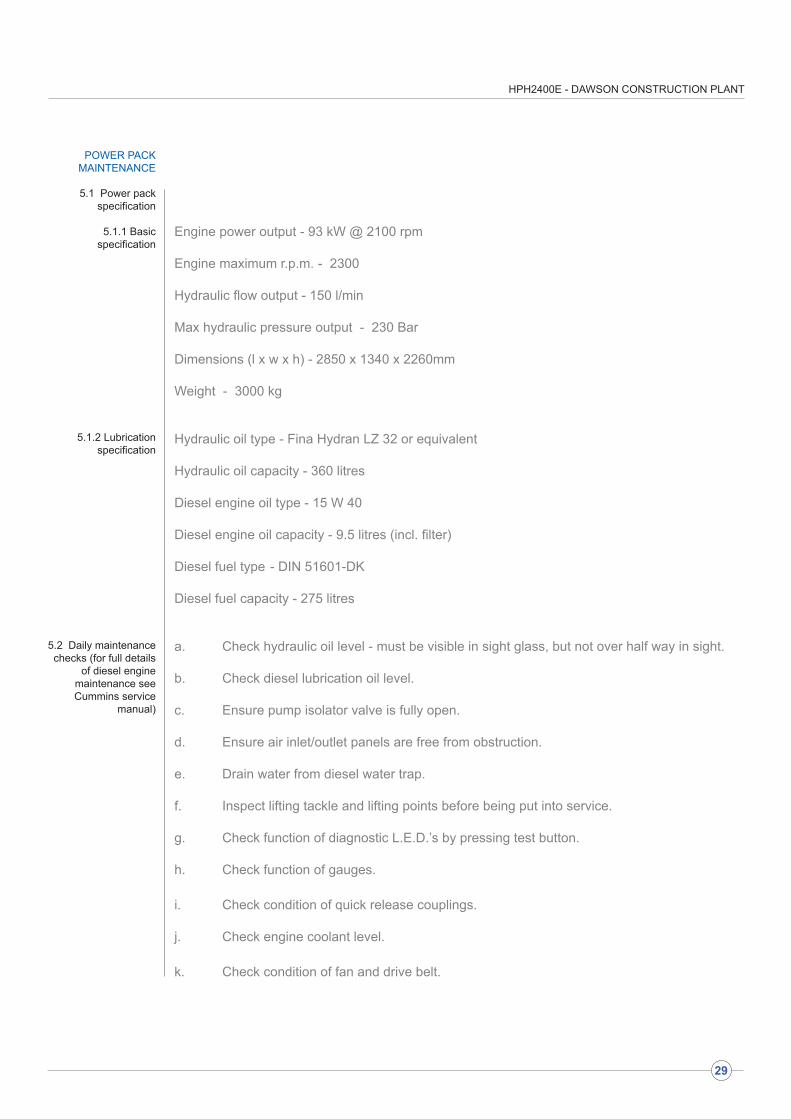
POWER PACK MAINTENANCE
Engine power output - 93 kW @ 2100 rpm Engine maximum r.p.m. - 2300
Hydraulic flow output - 150 l/min
Max hydraulic pressure output - 230 Bar
Dimensions (l x w x h) - 2850 x 1340 x 2260mm
Weight - 3000 kg
Hydraulic oil type - Fina Hydran LZ 32 or equivalent
Hydraulic oil capacity - 360 litres
Diesel engine oil type - 15 W 40
Diesel engine oil capacity - 9.5 litres (incl. filter)
Diesel fuel type - DIN 51601-DK
Diesel fuel capacity - 275 litres
a. Check hydraulic oil level - must be visible in sight glass, but not over half way in sight.
b. Check diesel lubrication oil level.
c. Ensure pump isolator valve is fully open.
d. Ensure air inlet/outlet panels are free from obstruction.
e. Drain water from diesel water trap.
f. Inspect lifting tackle and lifting points before being put into service.
g. Check function of diagnostic L.E.D.’s by pressing test button.
h. Check function of gauges.
i. Check condition of quick release couplings.
j. Check engine coolant level.
k. Check condition of fan and drive belt.
5.1 Power pack specification
5.1.1 Basic specification
5.1.2 Lubrication specification
5.2 Daily maintenance checks (for full details
of diesel engine maintenance see Cummins service
manual)
HPH2400E - DAWSON CONSTRUCTION PLANT
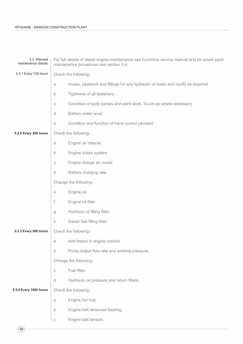
For full details of diesel engine maintenance see Cummins service manual and for power pack maintenance procedures see section 5.4.
Check the following:-
a. Hoses, pipework and fittings for any hydraulic oil leaks and rectify as required.
b. Tightness of all fasteners.
c. Condition of body panels and paint work. Touch-up where necessary.
d. Battery water level.
e. Condition and function of hand control pendant.
Check the following:-
a. Engine air cleaner.
b. Engine intake system
c. Engine charge air cooler.
d. Battery charging rate.
Change the following:-
e. Engine oil.
f. Engine oil filter.
g. Hydrauic oil filling filter.
h. Diesel fuel filling filter.
Check the following:-
a. Anti freeze in engine coolant.
b. Pump output flow rate and working pressure.
Change the following:-
c. Fuel filter. d. Hydraulic oil pressure and return filters.
Check the following:-
a. Engine fan hub.
b. Engine belt tensioner bearing.
c. Engine belt tension.
5.3 Planned maintenance checks
5.3.1 Every 125 hours
5.3.2 Every 250 hours
5.3.3 Every 500 hours
30
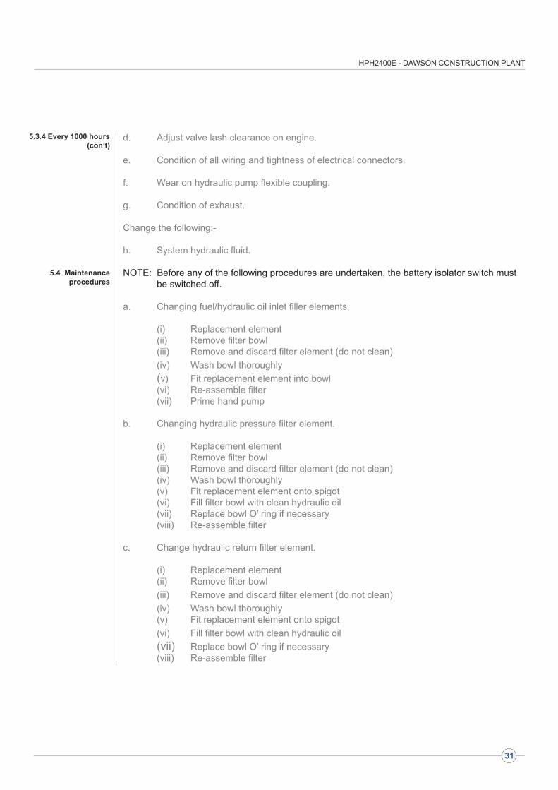
5.3.4 Every 1000 hours
HPH2400E - DAWSON CONSTRUCTION PLANT
d. Adjust valve lash clearance on engine.
e. Condition of all wiring and tightness of electrical connectors.
f. Wear on hydraulic pump flexible coupling.
g. Condition of exhaust.
Change the following:-
h. System hydraulic fluid.
NOTE: Before any of the following procedures are undertaken, the battery isolator switch must be switched off.
a. Changing fuel/hydraulic oil inlet filler elements.
(i) Replacement element (ii) Remove filter bowl (iii) Remove and discard filter element (do not clean) (iv) Wash bowl thoroughly (v) Fit replacement element into bowl (vi) Re-assemble filter (vii) Prime hand pump
b. Changing hydraulic pressure filter element.
(i) Replacement element (ii) Remove filter bowl (iii) Remove and discard filter element (do not clean) (iv) Wash bowl thoroughly (v) Fit replacement element onto spigot (vi) Fill filter bowl with clean hydraulic oil (vii) Replace bowl O’ ring if necessary (viii) Re-assemble filter
c. Change hydraulic return filter element.
(i) Replacement element (ii) Remove filter bowl (iii) Remove and discard filter element (do not clean) (iv) Wash bowl thoroughly (v) Fit replacement element onto spigot (vi) Fill filter bowl with clean hydraulic oil (vii) Replace bowl O’ ring if necessary (viii) Re-assemble filter
5.3.4 Every 1000 hours(con’t)
5.4 Maintenance procedures
31

HPH2400E - DAWSON CONSTRUCTION PLANT
d. Pump removal/re-fitting.
(i) IMPORTANT NOTE - the hydraulic pump should be returned to the manufacturer for repair/overhaul. This item must not be stripped or tampered with.(ii) Isolate pump from hydraulic oil reservoir using pump isolator valve(iii) Remove hoses from pump body(iv) Remove mounting screws from front flange of pump(v) Withdraw pump from coupling towards oil reservoir(vi) Remove bellhousing from engine mounting flange(vii) Reverse procedure for re-assembly(viii) Fill case drain of pump with clean hydraulic oil prior to start up following removal from the system (port located on the top of the pump with adaptor fitted)
e. Cooler removal/re-fitting.
(i) Close pump isolator valve to prevent system syphoning(ii) Remove flexible hoses from cooler(iii) Remove mounting bolts from cooler(iv) To remove matrix, remove top and bottom retaining strips from front of cooler and withdraw matrix from front of cooler assembly
f. Control valve assembly.
(i) Close pump isolator valve to prevent system syphoning(ii) To replace solenoid coils remove plastic retainer from end of coil and withdraw coil from retaining tube(iii) To replace valve assemblies remove 4 off retaining screws from top of valve and replace component as necessary
g. Pipework.
(i) For details of hose assemblies see hydraulic schematic drawing
(ii) In the event of steel pipe failure, 25mm 3 series fittings should be utilised in conjunction with 25mm bore x 3mm wall thickness tube
(iii) Welded pipe ends are currently utilised and should it become necessary to disturb these fittings a replacement O’ ring should be used
h. Changing system hydraulic fluid
(i) Change hydraulic fluid(ii) Remove cleanout cover and clean reservoir(iii) Replace fuel inlet and hydraulic fluid inlet filter elements(iv) Replace hydraulic pressure line filter element(v) Replace hydraulic return line filter element(vi) Blow through cooler matrix to clear(vii) Replace solid pipe fitting O’ rings as necessary(viii) Replace tank cover gasket(ix) Check all electrical connections for tightness(x) Check drive coupling for wear and replace or adjust if necessary
5.4 Maintenance procedures
(con’t)
32

HPH2400E - DAWSON CONSTRUCTION PLANT
33
a. Re-setting pressure The pressure regulating adjuster is situated on the main control valve assembly. To adjust:
(i) Loosen the lock nut and wind the centre spigot counter clockwise to reduce pressure(ii) Press the test button on the control panel to load the system(iii) Turn the centre spigot clockwise to raise the system pressure(iv) When the required pressure has been achieved (max 230 bar) tighten the lock nut
NOTE: Should the required pressure be exceeded, wind the adjuster back and increase again. Never wind the pressure downwards to set
b. Engine gauges replacement.
(i) There is a resistor fitted to all gauge power lines. This must be replaced after maintenance to prevent damage to the gauges.
5.5 Setting Procedures
HPH2400E - DAWSON CONSTRUCTION PLANT
34
FAU
LT F
IND
ING
CH
AR
T FO
R E
LEC
TRIC
HA
MM
ER
FA
ULT
= H
AM
ME
R D
OE
S N
OT
RU
N A
SS
UM
ING
TH
AT T
HE
PO
WE
R P
AC
K IS
DE
LIV
ER
ING
OIL
(C
HE
CK
GA
UG
ES
)
RE
MO
VE
PO
RT
IN C
OV
ER
CH
EC
K P
RO
XY
MO
DU
LES
US
ING
TE
ST
BO
X CO
NN
EC
T TE
ST
BO
X T
O P
RO
XY
MO
DU
LE P
LUG
, CH
EC
K F
OR
PO
WE
R
PU
SH
BU
TTO
NS
TO
SIM
ULA
TE P
RO
X
SE
NS
OR
S, C
HE
CK
MIM
IC S
CR
EE
N
FOR
PR
OX
SIG
NA
LS
CH
EC
K C
AR
TRID
GE
VA
LVE
S P
US
H
VALV
E O
VE
RR
IDE
BU
TTO
NS
IN
ELE
CTR
ICA
L E
NC
LOS
UR
E IF
UP
AN
D D
OW
N L
ED
s LI
GH
T C
IRC
UIT
IS
OK
PU
SH
VA
LVE
OV
ER
RID
E
BU
TTO
NS
, LIS
TEN
FO
R M
AIN
VA
LVE
SW
ITC
HIN
G C
HE
CK
G
AU
GE
, IT
SH
OU
LD D
IP A
S
THE
VA
LVE
CH
AN
GE
S
CH
AN
GE
ELE
CTR
ON
IC
CO
NTR
ON
ER
FO
R A
PR
OV
EN
UN
IT
PU
T H
AM
ME
R B
AC
K O
N
THE
PIL
E A
ND
TE
ST
CH
EC
K M
AIN
VA
LVE
CH
EC
K M
AIN
RA
M
HA
MM
ER
CO
NN
EC
TED
TO
PO
WE
R P
AC
K
AN
D L
AYIN
G O
N T
HE
GR
OU
ND
RE
PLA
CE
P
RO
XY
MO
DU
LE
NO
T O
KO
K
RE
PLA
CE
C
AB
LE
NO
T O
KO
K
NO
T O
KO
K
CH
AN
GE
C
AR
TRID
GE
VA
LVE
S
NO
T O
K
DIS
CO
NN
EC
T M
AIN
HY
DR
AU
LIC
S
UP
PLY
FR
OM
PO
WE
R P
AC
K
BU
T LE
AVE
PIL
OT
SU
PP
LY
CO
NN
EC
TED
. STA
RT
PO
WE
R
PAC
K A
ND
RU
N T
HE
HA
MM
ER
NO
T O
K
NO
T O
K
OK
OK
HPH2400E - DAWSON CONSTRUCTION PLANT
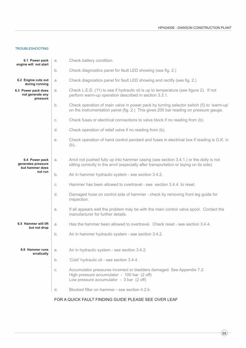
a. Check battery condition.
b. Check diagnostics panel for fault LED showing (see fig. 2.)
a. Check diagnostics panel for fault LED showing and rectify (see fig. 2.)
a. Check L.E.D. (11) to see if hydraulic oil is up to temperature (see figure 2). If not perform warm-up operation described in section 3.3.1.
b. Check operation of main valve in power pack by turning selector switch (5) to ‘warm-up’ on the instrumentation panel (fig. 2.) This gives 200 bar reading on pressure gauge.
c. Check fuses or electrical connections to valve block if no reading from (b).
d. Check operation of relief valve if no reading from (b).
e. Check operation of hand control pendant and fuses in electrical box if reading is O.K. in (b).
a. Anvil not pushed fully up into hammer casing (see section 3.4.1.) or the dolly is not sitting correctly in the anvil (especially after transportation or laying on its side)
b. Air in hammer hydraulic system - see section 3.4.2.
c. Hammer has been allowed to overtravel - see section 3.4.4. to reset.
d. Damaged hose on control side of hammer - check by removing front leg guide for inspection. e. If all appears well the problem may be with the main control valve spool. Contact the manufacturer for further details.
a. Has the hammer been allowed to overtravel. Check reset - see section 3.4.4.
b. Air in hammer hydraulic system - see section 3.4.2.
a. Air in hydraulic system - see section 3.4.2.
b. ‘Cold’ hydraulic oil - see section 3.4.4.
c. Accumulator pressures incorrect or bladders damaged. See Appendix 7.2. High pressure accumulator - 100 bar (2 off) Low pressure accumulator - 3 bar (2 off)
d. Blocked filter on hammer - see section 4.2.b.
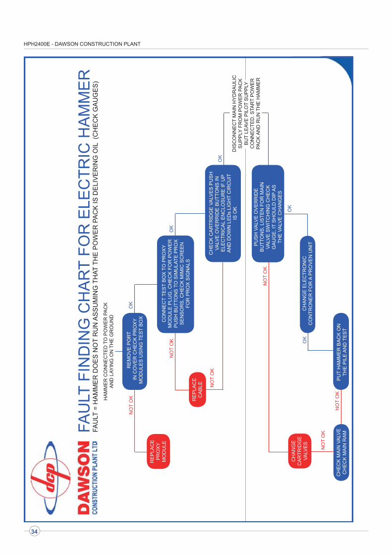
FOR A QUICK FAULT FINDING GUIDE PLEASE SEE OVER LEAF
TROUBLESHOOTING
6.1 Power pack engine will not start
6.2 Engine cuts out during running
6.3 Power pack does not generate any
pressure
6.4 Power pack generates pressure
but hammer does not run
6.5 Hammer will lift but not drop
6.6 Hammer runs erratically
35
- - - - - -
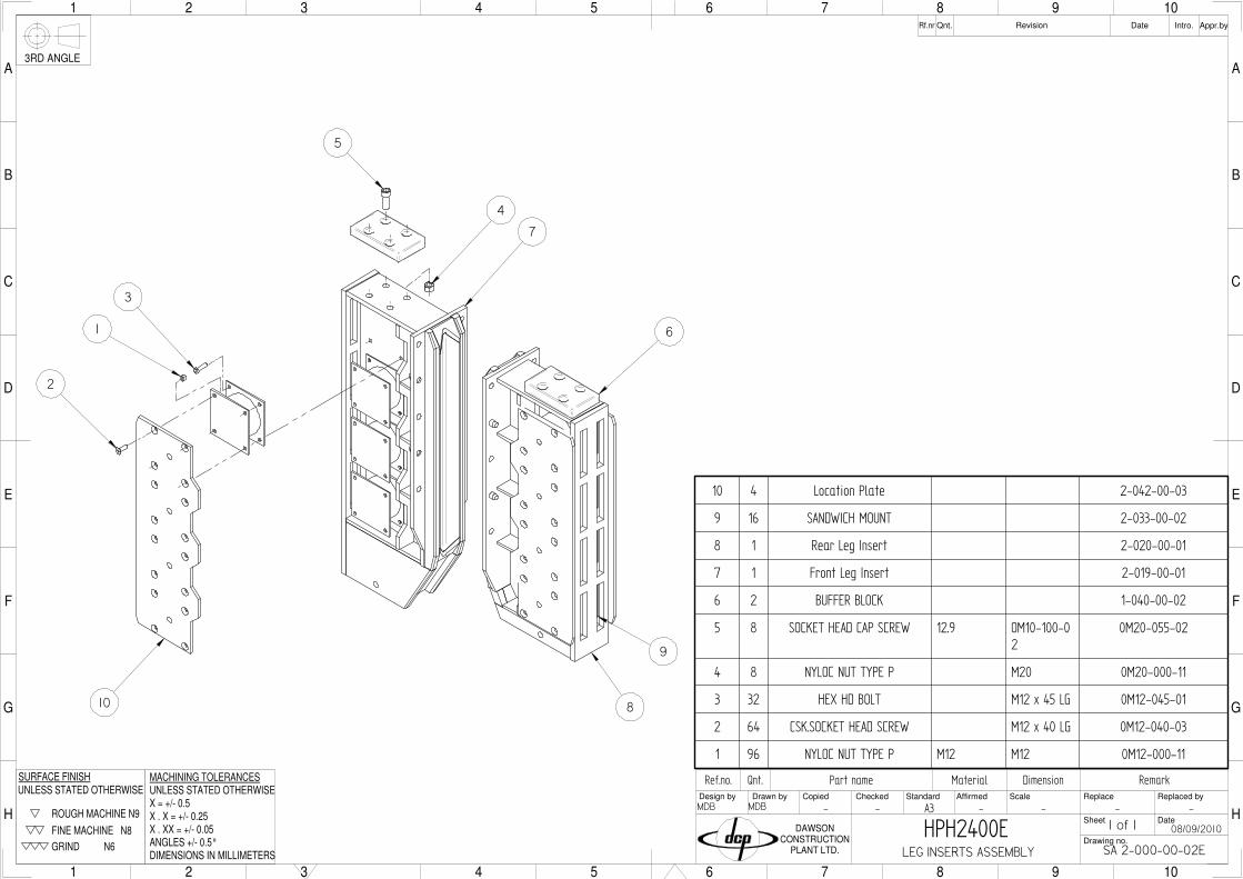
GA 2-000-00-02
09/09/2010
MDB MDB
Qnt.
G
M
L
1 2 3
K
J
H
I
4 5 6 7 8 9
F
E
D
C
B
A
1 2 3 4 5 6 7 8 9
G
10 11 12 13 14 15 16 17 18 19
M
L
K
J
H
I
10 11 12 13 14 15
F
E
D
C
16 17 18
B
A
19
CopiedDesign by
Ref.no.Drawn by Checked
Part nameStandard ScaleAffirmed
Material Dimension Remark
Drawing no.
Sheet
Replace
Date
Replaced by
Qnt.Rf.nr Revision Appr.byDate Intro.
DAWSONCONSTRUCTION
PLANT LTD.
3RD ANGLE
ROUGH MACHINE N9
FINE MACHINE N8
GRIND N6
UNLESS STATED OTHERWISESURFACE FINISH
X . X = +/- 0.25
ANGLES +/- 0.5°
MACHINING TOLERANCESUNLESS STATED OTHERWISE
X . XX = +/- 0.05
DIMENSIONS IN MILLIMETERS
X = +/- 0.5 A0
1 of 1HPH2400EGENERAL ASSEMBLY
A
A
SECTION A-A
13
22
25
27
29
16
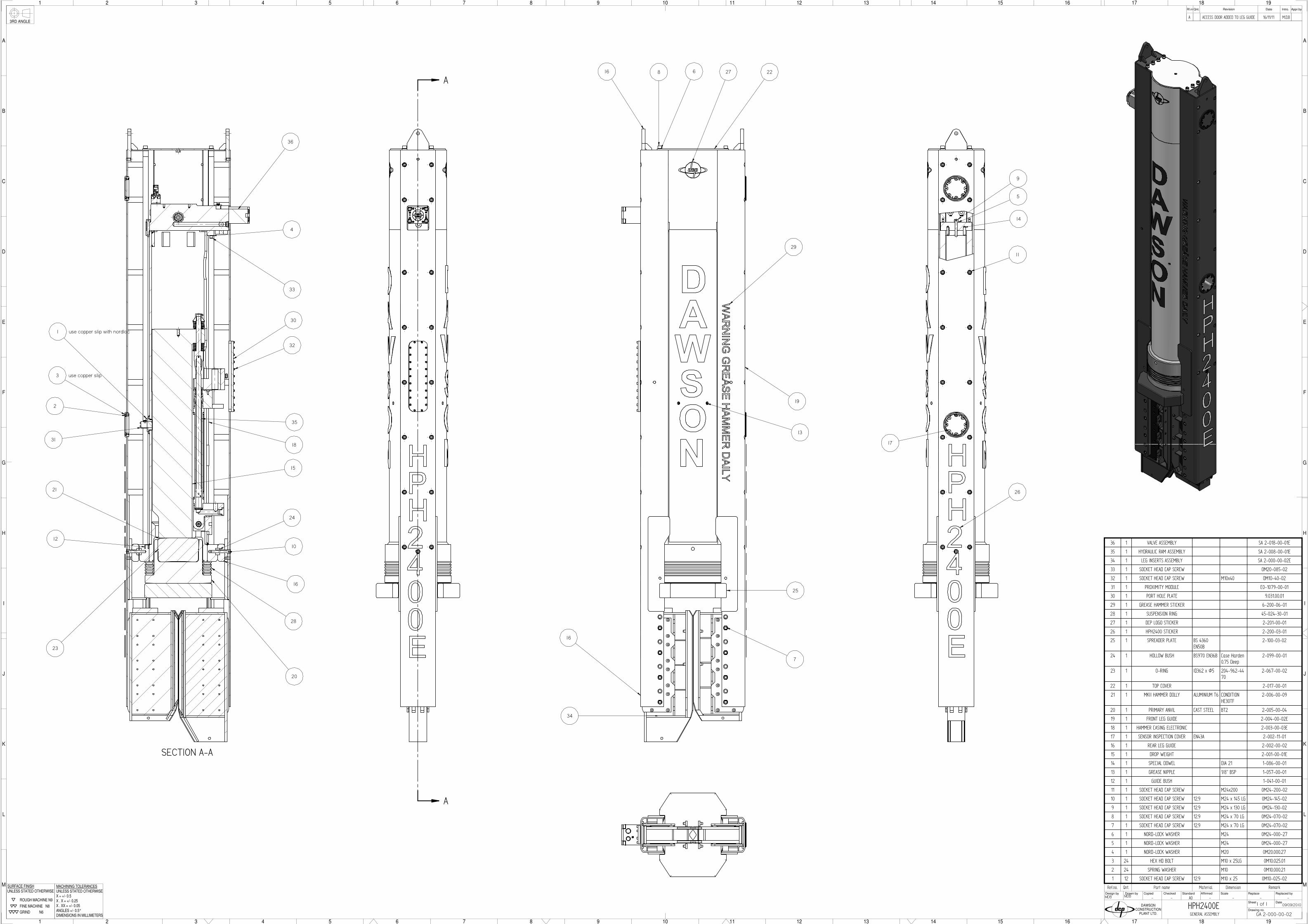
36 1 VALVE ASSEMBLY SA 2-018-00-01E
35 1 HYDRAULIC RAM ASSEMBLY SA 2-008-00-01E
34 1 LEG INSERTS ASSEMBLY SA 2-000-00-02E
33 1 SOCKET HEAD CAP SCREW OM20-085-02
32 1 SOCKET HEAD CAP SCREW M10x40 OM10-40-02
31 1 PROXIMITY MODULE E0-1079-00-01
30 1 PORT HOLE PLATE 9.031.00.01
29 1 GREASE HAMMER STICKER 6-200-06-01
28 1 SUSPENSION RING 45-024-30-01
27 1 DCP LOGO STICKER 2-201-00-01
26 1 HPH2400 STICKER 2-200-03-01
25 1 SPREADER PLATE BS 4360EN50B
2-100-03-02
24 1 HOLLOW BUSH BS970 EN36B Case Harden0.75 Deep
2-099-00-01
23 1 O-RING ID362 x Ø5 204-962-4470
2-067-00-02
22 1 TOP COVER 2-017-00-01
21 1 MKII HAMMER DOLLY ALUMINIUM T6 CONDITIONHE30TF
2-006-00-09
20 1 PRIMARY ANVIL CAST STEEL BT2 2-005-00-04
19 1 FRONT LEG GUIDE 2-004-00-02E
18 1 HAMMER CASING ELECTRONIC 2-003-00-03E
17 1 SENSOR INSPECTION COVER EN43A 2-002-11-01
16 1 REAR LEG GUIDE 2-002-00-02
15 1 DROP WEIGHT 2-001-00-01E
14 1 SPECIAL DOWEL DIA 21 1-086-00-01
13 1 GREASE NIPPLE 1/8" BSP 1-057-00-01
12 1 GUIDE BUSH 1-041-00-01
11 1 SOCKET HEAD CAP SCREW M24x200 0M24-200-02
10 1 SOCKET HEAD CAP SCREW 12.9 M24 x 145 LG 0M24-145-02
9 1 SOCKET HEAD CAP SCREW 12.9 M24 x 130 LG 0M24-130-02
8 1 SOCKET HEAD CAP SCREW 12.9 M24 x 70 LG 0M24-070-02
7 1 SOCKET HEAD CAP SCREW 12.9 M24 x 70 LG 0M24-070-02
6 1 NORD-LOCK WASHER M24 0M24-000-27
5 1 NORD-LOCK WASHER M24 0M24-000-27
4 1 NORD-LOCK WASHER M20 0M20.000.27
3 24 HEX HD BOLT M10 x 25LG 0M10.025.01
2 24 SPRING WASHER M10 0M10.000.21
1 12 SOCKET HEAD CAP SCREW 12.9 M10 x 25 0M10-025-02
28
16
16
19
20
12
10
24
21
1 use copper slip with nordloc
3 use copper slip
2
34
36
18
8 6
15
33
4
7
35
26
11
14
9
5
17
30
32
A ACCESS DOOR ADDED TO LEG GUIDE 16/11/11 M.D.B
23
31
- - - - - -
Qnt.Ref.no. Part name Material Dimension Remark
F
K
J
1 2
I
H
G
3 4 5 6 7
E
D
C
B
A
1 2 3 4 5 6 7
F
8 9 10 11 12 13 14 15
K
J
I
H
G
8 9 10 11 12
E
D
C
13 14 15
B
A
CopiedDesign by Drawn by Checked Standard ScaleAffirmed
Drawing no.
Sheet
Replace
Date
Replaced by
Qnt.Rf.nr Revision Appr.byDate Intro.
DAWSONCONSTRUCTION
PLANT LTD.
3RD ANGLE
ROUGH MACHINE N9
FINE MACHINE N8
GRIND N6
UNLESS STATED OTHERWISESURFACE FINISH
X . X = +/- 0.25
ANGLES +/- 0.5°
MACHINING TOLERANCESUNLESS STATED OTHERWISE
X . XX = +/- 0.05
DIMENSIONS IN MILLIMETERS
X = +/- 0.5 A1
SA 2-008-00-01E
09/09/2010
MDBMDB
HYDRAULIC RAM ASSEMBLY
1 of 2HPH2400E
19
33
35
39
10 use green loctite
15
13 18
49 1 SEAL CLARON CS50500/2B
48 1 ANTI EXTRUSION RING 6-008-30-01
47 1 O RING 6-008-29-01
46 1 TOLERANCE WASHER 6-008-28-01
45 1 PHOSPHER BRONZE 6-008-27-03
44 1 ANTI-EXTRUSION RING 6-008-25-01
43 1 O RING 6-008-24-01
42 1 BOTTOM BLOCK 6-008-06-02
41 1 HPH6500 HYDRAULICRAM TOP BLOCK
6-008-05-04
40 2 BANJO COUPLING 4216
39 2 HARDENED INNER BUSH 2-098-00-01
38 1 HARDENED INNER BUSH 2-097-00-01
37 1 Ram Guide Block 2-032-00-02
36 16 Disc Spring 2-022-00-01
35 1 Ram Anchor 2-021-00-02
34 2 DISC SPRING GUIDE BUSH 2-015-00-02
33 1 PIN RETAINER 2-014-00-01
32 1 LOWER RAM PIN 2-013-00-02
31 1 DISC SPRING BUFFER WASHER 2-012-00-04
30 1 CONNECTOR NUT 2-011-00-03
29 1 DISC SPRING BUFFER WASHER 2-010-00-05
28 1 RAM CONNECTOR - 4x2 DISCSPRING
2-009-00-04
27 1 O RING 2-008-27-01
26 1 PLUG 2-008-26-01
25 1 PISTON SEAL (ROUGH) 2-008-23-01
24 2 SLYD RING (ROUGH) 2-008-22-01
23 2 ROD SEAL (ROUGH) 2-008-21-02
22 1 EXCLUDER 2-008-20-01
21 1 HYDRAULIC RAM BARREL 2-008-04-02
20 1 HYDRAULIC RAM ROD 2-008-03-03.2
19 2 WEAR PAD 1-015-00-01
18 8 SOCKET HEAD CAP SCREW 12.9 M24 x 60 LG 0M24-060-02
17 6 SOCKET HEAD CAP SCREW 0M16.170.02
16 8 NORD-LOCK WASHER M16 0M16.000.27
15 1 HEX HD BOLT M16 x 115 LG 0M16-115-01
14 8 SOCKET HEAD CAP SCREW 12.9 M16 x 60 LG 0M16-060-02
13 1 NYLOC NUT - TYPE T M16 0M16-000-12
12 2 SPRING PIN ø 12 x 40LG
0M12-040-22
11 1 SPRING PIN Ø10 x 70LG
0M10-070-22
10 4 CSK.SOC SET SCREW M10 x 16 LG 0M10-016-03
9 3 NORD-LOCK WASHER M8 0M08.000.27
8 3 DOG POINT SET SCREW M8 x 30 LG 0M08-030-16
7 2 CONE POINT SET SCREW M8 x 10 0M08-010-17
6 3 NYLOC NUT - TYPE T M8 0M08-000-12
5 1 SPRING PIN Ø6 x 70 LG 0M06-070-22
4 1 6MM SLOTTED SPRING PIN 0M06-045-22
3 2 SHOCKER WEAR STRIP
2 1 SHOCKER PISTON
1 1 RAM SHOCKER
16
26
27
14
16
32
42
38
39
A 6MM SPRING PIN ADDED 27/06/12 MDB
A
B PART REVISION UPDATES 05/10/12 MDB
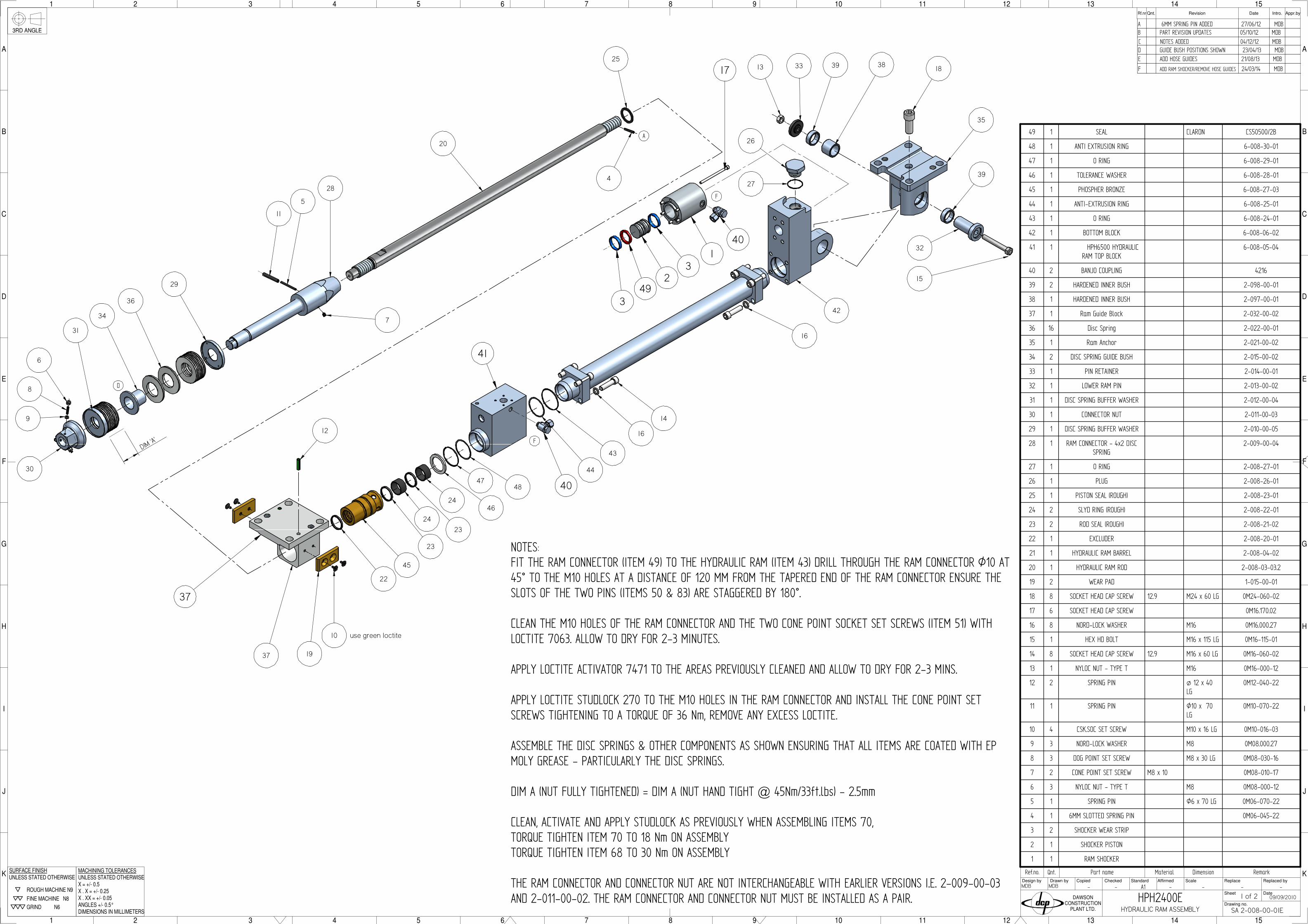
NOTES:FIT THE RAM CONNECTOR (ITEM 49) TO THE HYDRAULIC RAM (ITEM 43) DRILL THROUGH THE RAM CONNECTOR Ø10 AT45° TO THE M10 HOLES AT A DISTANCE OF 120 MM FROM THE TAPERED END OF THE RAM CONNECTOR ENSURE THESLOTS OF THE TWO PINS (ITEMS 50 & 83) ARE STAGGERED BY 180°.
CLEAN THE M10 HOLES OF THE RAM CONNECTOR AND THE TWO CONE POINT SOCKET SET SCREWS (ITEM 51) WITHLOCTITE 7063. ALLOW TO DRY FOR 2-3 MINUTES.
APPLY LOCTITE ACTIVATOR 7471 TO THE AREAS PREVIOUSLY CLEANED AND ALLOW TO DRY FOR 2-3 MINS.
APPLY LOCTITE STUDLOCK 270 TO THE M10 HOLES IN THE RAM CONNECTOR AND INSTALL THE CONE POINT SETSCREWS TIGHTENING TO A TORQUE OF 36 Nm, REMOVE ANY EXCESS LOCTITE.
ASSEMBLE THE DISC SPRINGS & OTHER COMPONENTS AS SHOWN ENSURING THAT ALL ITEMS ARE COATED WITH EPMOLY GREASE - PARTICULARLY THE DISC SPRINGS.
DIM A (NUT FULLY TIGHTENED) = DIM A (NUT HAND TIGHT @ 45Nm/33ft.lbs) - 2.5mm
CLEAN, ACTIVATE AND APPLY STUDLOCK AS PREVIOUSLY WHEN ASSEMBLING ITEMS 70,TORQUE TIGHTEN ITEM 70 TO 18 Nm ON ASSEMBLYTORQUE TIGHTEN ITEM 68 TO 30 Nm ON ASSEMBLY
THE RAM CONNECTOR AND CONNECTOR NUT ARE NOT INTERCHANGEABLE WITH EARLIER VERSIONS I.E. 2-009-00-03AND 2-011-00-02. THE RAM CONNECTOR AND CONNECTOR NUT MUST BE INSTALLED AS A PAIR.
D GUIDE BUSH POSITIONS SHOWN 23/04/13 MDB
DIM 'A'
C NOTES ADDED 04/12/12 MDB
D
37
25
4
20
11
5
28
7
29
36
34
31
6
8
9
30
12
E ADD HOSE GUIDES 21/08/13 MDB
43
44
22
45
23
24
23
2446
4748
17
401
32
493
40
41
37
F ADD RAM SHOCKER/REMOVE HOSE GUIDES 24/03/14 MDB
F
F
- - - - - -
-
SA 2-018-00-01E
09/09/2010
SDD SDD
VALVE ASSEMBLY
Qnt.
G
M
L
1 2 3
K
J
H
I
4 5 6 7 8 9
F
E
D
C
B
A
1 2 3 4 5 6 7 8 9
G
10 11 12 13 14 15 16 17 18 19
M
L
K
J
H
I
10 11 12 13 14 15
F
E
D
C
16 17 18
B
A
19
CopiedDesign by
Ref.no.
Drawn by Checked
Part name
Standard ScaleAffirmed
Material Dimension Remark
Drawing no.
File
Replace
Date
Replaced by
Qnt.Rf.nr Revision Appr.byDate Intro.
DAWSONCONSTRUCTION
PLANT LTD.
3RD ANGLE
ROUGH MACHINE N9
FINE MACHINE N8
GRIND N6
UNLESS STATED OTHERWISESURFACE FINISH
X . X = +/- 0.25
ANGLES +/- 0.5°
MACHINING TOLERANCESUNLESS STATED OTHERWISE
X . XX = +/- 0.05
DIMENSIONS IN MILLIMETERS
X = +/- 0.5 A0
19
14
15
18
17
16
12
9
5
22
13
24
3
25
2
20
6
3 21
7
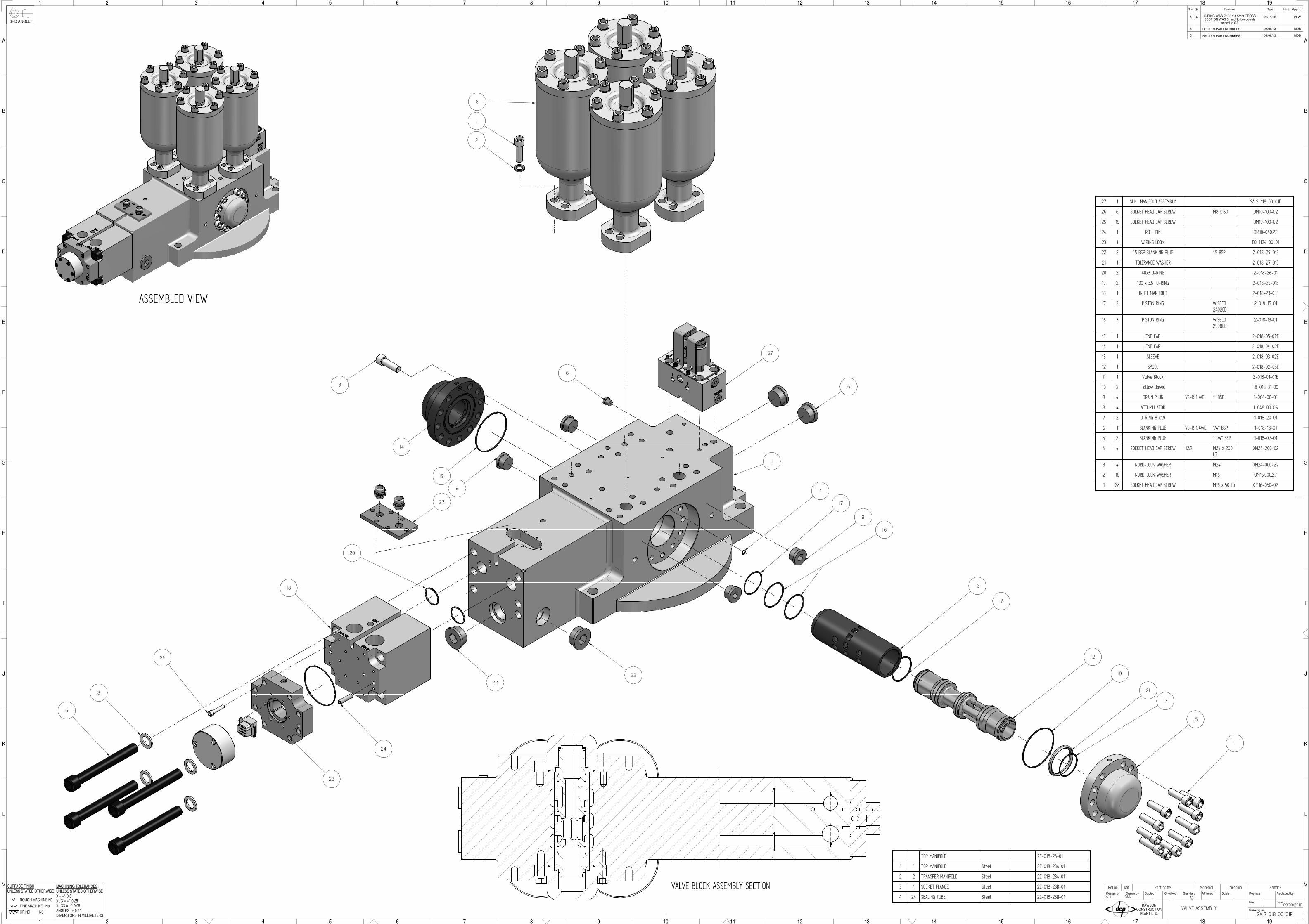
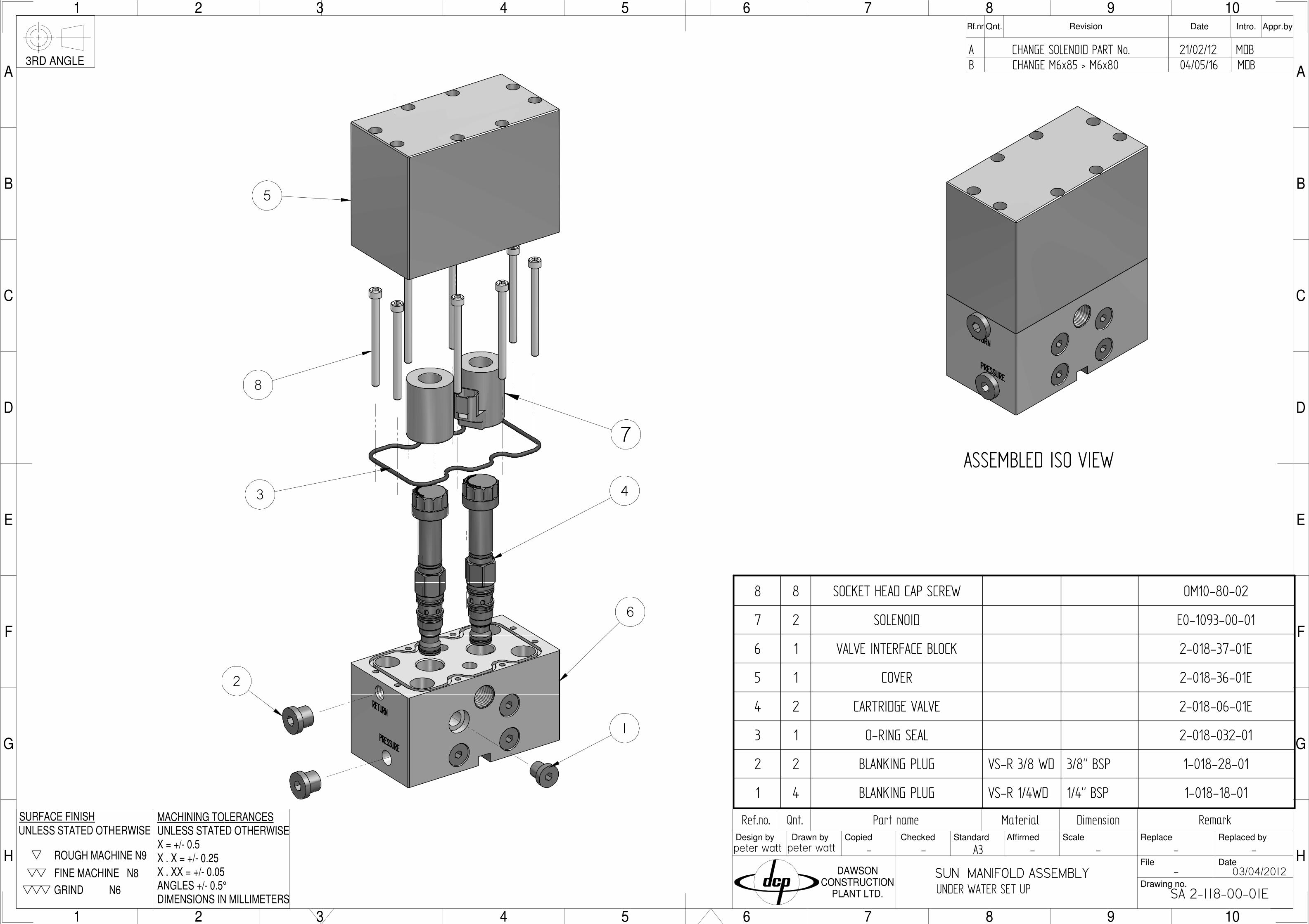
27 1 SUN MANIFOLD ASSEMBLY SA 2-118-00-01E
26 6 SOCKET HEAD CAP SCREW M8 x 60 OM10-100-02
25 15 SOCKET HEAD CAP SCREW OM10-100-02
24 1 ROLL PIN OM10-040.22
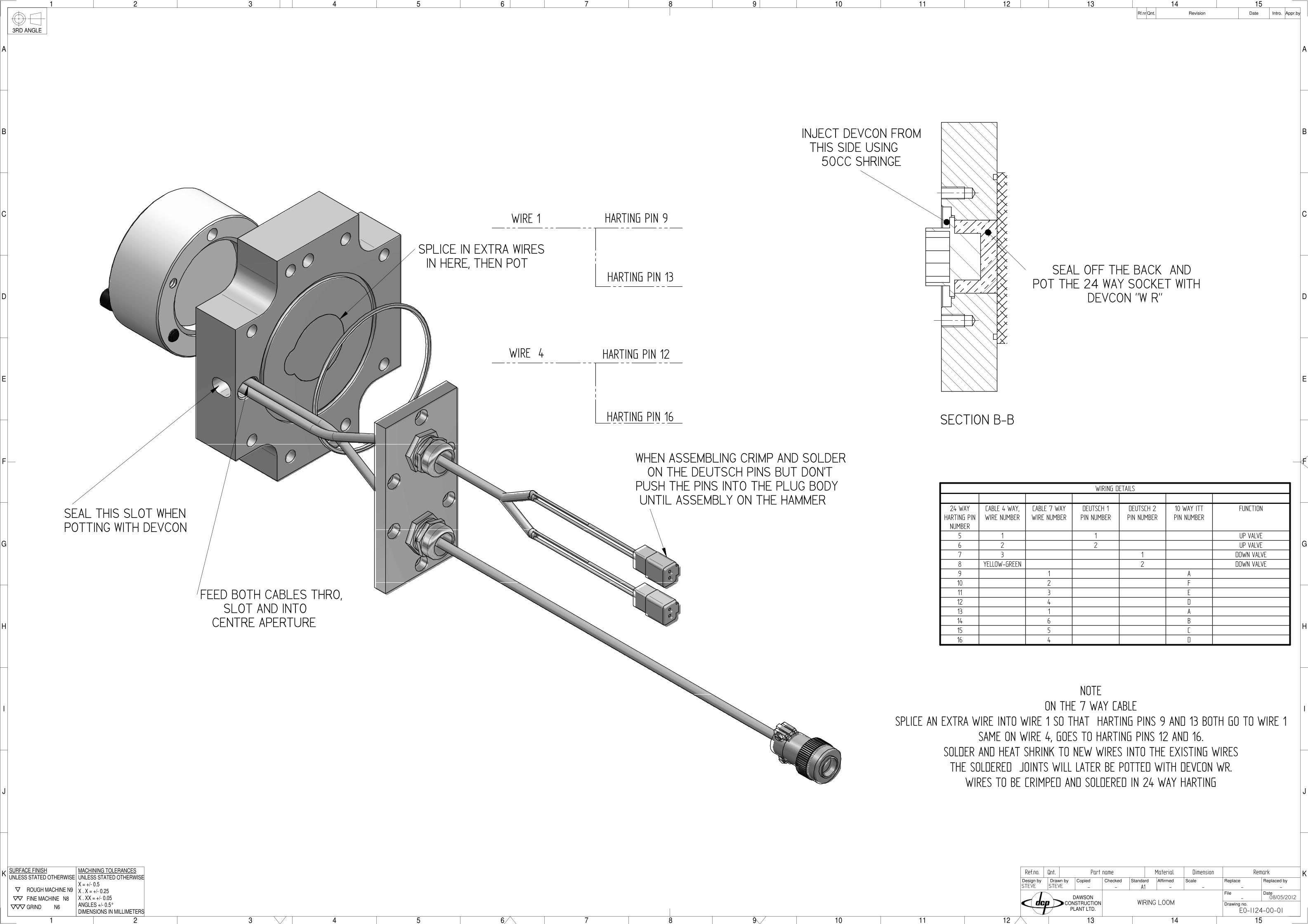
23 1 WIRING LOOM E0-1124-00-01
22 2 1.5 BSP BLANKING PLUG 1.5 BSP 2-018-29-01E
21 1 TOLERANCE WASHER 2-018-27-01E
20 2 40x3 O-RING 2-018-26-01
19 2 100 x 3.5 O-RING 2-018-25-01E
18 1 INLET MANIFOLD 2-018-23-03E
17 2 PISTON RING WISECO2402CD
2-018-15-01
16 3 PISTON RING WISECO2598CD
2-018-13-01
15 1 END CAP 2-018-05-02E
14 1 END CAP 2-018-04-02E
13 1 SLEEVE 2-018-03-02E
12 1 SPOOL 2-018-02-05E
11 1 Valve Block 2-018-01-01E
10 2 Hollow Dowel 18-018-31-00
9 4 DRAIN PLUG VS-R 1 WD 1" BSP 1-064-00-01
8 4 ACCUMULATOR 1-048-00-06
7 2 O-RING 8 x1.9 1-018-20-01
6 1 BLANKING PLUG VS-R 1/4WD 1/4" BSP 1-018-18-01
5 2 BLANKING PLUG 1 1/4" BSP 1-018-07-01
4 4 SOCKET HEAD CAP SCREW 12.9 M24 x 200LG
0M24-200-02
3 4 NORD-LOCK WASHER M24 0M24-000-27
2 16 NORD-LOCK WASHER M16 0M16.000.27
1 28 SOCKET HEAD CAP SCREW M16 x 50 LG 0M16-050-02
VALVE BLOCK ASSEMBLY SECTION
1
22
9
6
19
8
1
11
ASSEMBLED VIEW
Qnt.A O-RING WAS Ø100 x 3.5mm CROSSSECTION WAS 3mm, Hollow dowels
added to GA
PLW28/11/12
23
23
B RE-ITEM PART NUMBERS MDB08/05/13
C RE-ITEM PART NUMBERS MDB04/06/13
16
17
TOP MANIFOLD 2C-018-23-01
1 1 TOP MANIFOLD Steel 2C-018-23A-01
2 2 TRANSFER MANIFOLD Steel 2C-018-23A-01
3 1 SOCKET FLANGE Steel 2C-018-23B-01
4 24 SEALING TUBE Steel 2C-018-23D-01
27
-
-----
SA 2-118-00-01E
03/04/2012
peter wattpeter watt
SUN MANIFOLD ASSEMBLY
-
Qnt.Ref.no. Part name Material Dimension Remark
1
H
G
F
2 3 4 5 6 7 8 9 10
H
G
F
E
7 8
D
C
B
9 10
A
CopiedDesign by Drawn by Checked Standard ScaleAffirmed
Drawing no.
File
Replace
Date
Replaced by
Qnt.Rf.nr Revision Appr.byDate Intro.
DAWSONCONSTRUCTION
PLANT LTD.
ROUGH MACHINE N9
FINE MACHINE N8
GRIND N6
UNLESS STATED OTHERWISESURFACE FINISH
X . X = +/- 0.25
ANGLES +/- 0.5°
MACHINING TOLERANCESUNLESS STATED OTHERWISE
X . XX = +/- 0.05
DIMENSIONS IN MILLIMETERS
X = +/- 0.5 A3
E
D
C
B
A
1 2 3 4 5 6
3RD ANGLE
UNDER WATER SET UP
8 8 SOCKET HEAD CAP SCREW OM10-80-02
7 2 SOLENOID E0-1093-00-01
6 1 VALVE INTERFACE BLOCK 2-018-37-01E
5 1 COVER 2-018-36-01E
4 2 CARTRIDGE VALVE 2-018-06-01E
3 1 O-RING SEAL 2-018-032-01
2 2 BLANKING PLUG VS-R 3/8 WD 3/8" BSP 1-018-28-01
1 4 BLANKING PLUG VS-R 1/4WD 1/4" BSP 1-018-18-01
1
8
3
5
2
4
6
ASSEMBLED ISO VIEW
A CHANGE SOLENOID PART No. 21/02/12 MDBB CHANGE M6x85 > M6x80 04/05/16 MDB
7
- - - - - -
-
Qnt.Ref.no. Part name Material Dimension Remark
F
K
J
1 2
I
H
G
3 4 5 6 7
E
D
C
B
A
1 2 3 4 5 6 7
F
8 9 10 11 12 13 14 15
K
J
I
H
G
8 9 10 11 12
E
D
C
13 14 15
B
A
CopiedDesign by Drawn by Checked Standard ScaleAffirmed
Drawing no.
File
Replace
Date
Replaced by
Qnt.Rf.nr Revision Appr.byDate Intro.
DAWSONCONSTRUCTION
PLANT LTD.
3RD ANGLE
ROUGH MACHINE N9
FINE MACHINE N8
GRIND N6
UNLESS STATED OTHERWISESURFACE FINISH
X . X = +/- 0.25
ANGLES +/- 0.5°
MACHINING TOLERANCESUNLESS STATED OTHERWISE
X . XX = +/- 0.05
DIMENSIONS IN MILLIMETERS
X = +/- 0.5 A1
E0-1124-00-01
08/05/2012
STEVESTEVE
WIRING LOOM
WIRE 1
HARTING PIN 13
HARTING PIN 9
HARTING PIN 12
HARTING PIN 16
WIRE 4
SECTION B-B
SEAL OFF THE BACK AND POT THE 24 WAY SOCKET WITH DEVCON "W R"
INJECT DEVCON FROM THIS SIDE USING 50CC SHRINGE
FEED BOTH CABLES THRO, SLOT AND INTO CENTRE APERTURE
SEAL THIS SLOT WHENPOTTING WITH DEVCON
WIRING DETAILS
24 WAYHARTING PINNUMBER
CABLE 4 WAY,WIRE NUMBER
CABLE 7 WAYWIRE NUMBER
DEUTSCH 1PIN NUMBER
DEUTSCH 2PIN NUMBER
10 WAY ITTPIN NUMBER
FUNCTION
5 1 1 UP VALVE6 2 2 UP VALVE7 3 1 DOWN VALVE8 YELLOW-GREEN 2 DOWN VALVE9 1 A10 2 F11 3 E12 4 D13 1 A14 6 B15 5 C16 4 D
NOTEON THE 7 WAY CABLE
SPLICE AN EXTRA WIRE INTO WIRE 1 SO THAT HARTING PINS 9 AND 13 BOTH GO TO WIRE 1SAME ON WIRE 4, GOES TO HARTING PINS 12 AND 16.
SOLDER AND HEAT SHRINK TO NEW WIRES INTO THE EXISTING WIRESTHE SOLDERED JOINTS WILL LATER BE POTTED WITH DEVCON WR.
WIRES TO BE CRIMPED AND SOLDERED IN 24 WAY HARTING
SPLICE IN EXTRA WIRES IN HERE, THEN POT
WHEN ASSEMBLING CRIMP AND SOLDER ON THE DEUTSCH PINS BUT DON'TPUSH THE PINS INTO THE PLUG BODY UNTIL ASSEMBLY ON THE HAMMER
1
H
G
F
2 3 4 5 6 7 8 9 10
H
G
F
E
7 8
D
C
B
9 10
A
CopiedDesign by Drawn by Checked Standard ScaleAffirmed
Drawing no.
Sheet
Replace
Date
Replaced by
Qnt.Rf.nr Revision Appr.byDate Intro.
DAWSONCONSTRUCTION
PLANT LTD.
ROUGH MACHINE N9
FINE MACHINE N8GRIND N6
UNLESS STATED OTHERWISESURFACE FINISH
X . X = +/- 0.25
ANGLES +/- 0.5°
MACHINING TOLERANCESUNLESS STATED OTHERWISE
X . XX = +/- 0.05
DIMENSIONS IN MILLIMETERS
X = +/- 0.5
E
D
C
B
A
1 2 3 4 5 6
3RD ANGLE
- - - - - -
08/05/2013
MDBMDB
Qnt.Ref.no. Part name Material Dimension Remark
1 2
J
I
H
G
F
3 4 5 6
E
D
C
B
A
1 2 3 4 5 6
7 8 9 10 11 12
J
I
H
G
F
7 8 9 10
E
D
C
11 12
B
A
CopiedDesign by Drawn by Checked Standard ScaleAffirmed
Drawing no.
Sheet
Replace
Date
Replaced by
Qnt.Rf.nr Revision Appr.byDate Intro.
DAWSONCONSTRUCTION
PLANT LTD.
3RD ANGLE
ROUGH MACHINE N9
FINE MACHINE N8
GRIND N6
UNLESS STATED OTHERWISESURFACE FINISH
X . X = +/- 0.25
ANGLES +/- 0.5°
MACHINING TOLERANCESUNLESS STATED OTHERWISE
X . XX = +/- 0.05
DIMENSIONS IN MILLIMETERS
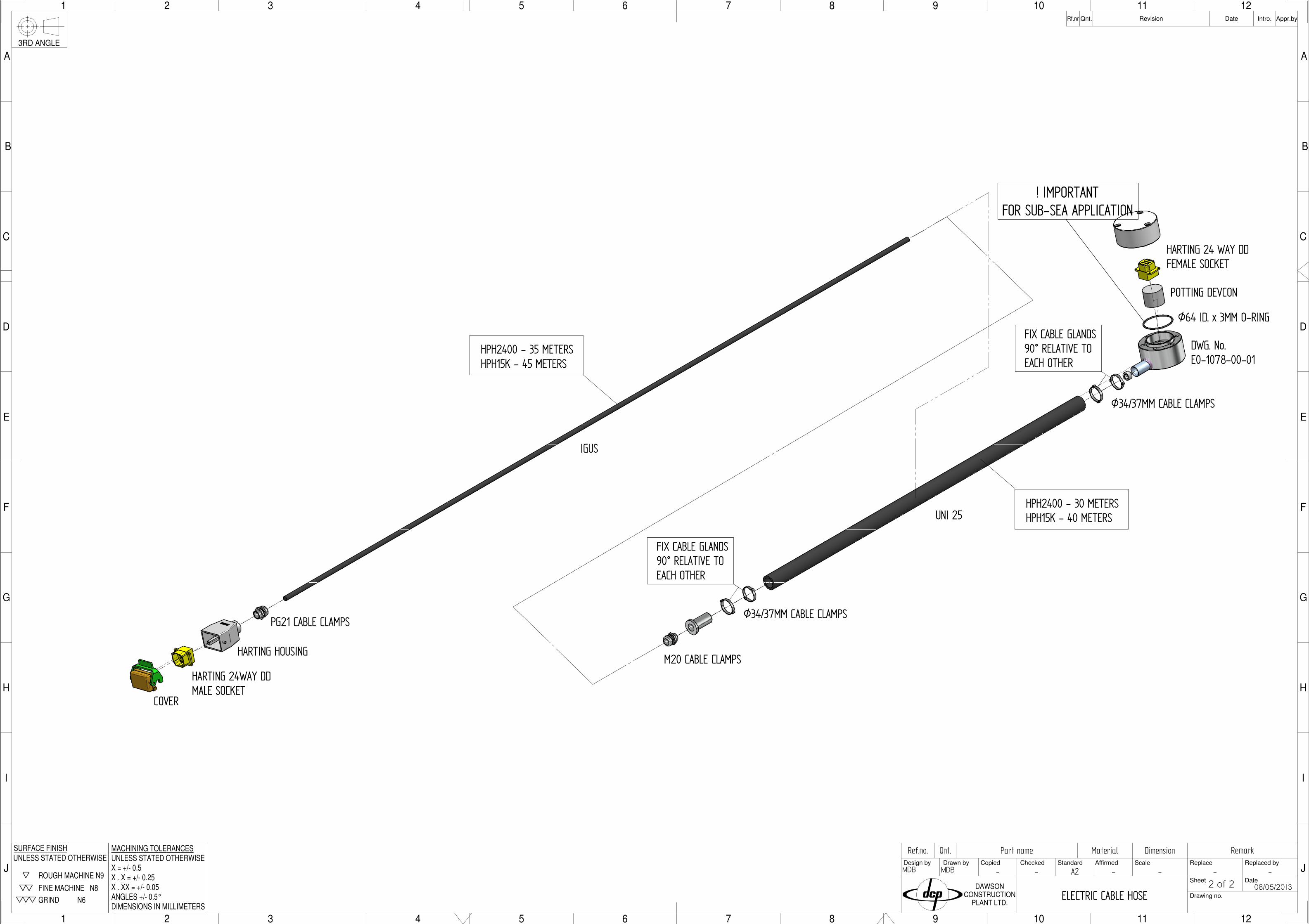
X = +/- 0.5 A22 of 2
COVER
HARTING 24WAY DDMALE SOCKET
HARTING HOUSING
PG21 CABLE CLAMPS
IGUS
HPH2400 - 35 METERSHPH15K - 45 METERS
M20 CABLE CLAMPS
Ø34/37MM CABLE CLAMPS
FIX CABLE GLANDS90° RELATIVE TOEACH OTHER
UNI 25HPH2400 - 30 METERSHPH15K - 40 METERS
Ø34/37MM CABLE CLAMPS
FIX CABLE GLANDS90° RELATIVE TOEACH OTHER
DWG. No.E0-1078-00-01
Ø64 ID. x 3MM O-RING
POTTING DEVCON
HARTING 24 WAY DDFEMALE SOCKET
! IMPORTANTFOR SUB-SEA APPLICATION
ELECTRIC CABLE HOSE
3RD ANGLE
X = +/- 0.5
DIMENSIONS IN MILLIMETERS
X . XX = +/- 0.05
UNLESS STATED OTHERWISEMACHINING TOLERANCES
ANGLES +/- 0.5°
X . X = +/- 0.25
SURFACE FINISH
UNLESS STATED OTHERWISE
GRIND N6
FINE MACHINE N8
ROUGH MACHINE N9
Intro.Date Appr.byRevisionRf.nr Qnt.
DAWSONCONSTRUCTION
PLANT LTD.
Replaced by
Date
Replace
Sheet
Drawing no.
Affirmed ScaleStandardCheckedDrawn byDesign by Copied
A
5
B
C
D
43
E
F
G
H
543
21
A
B
C
D
21
E
G
F
H
HPH2400E - DAWSON CONSTRUCTION PLANT
36
HPH2400E - DAWSON CONSTRUCTION PLANT
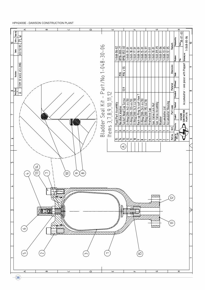
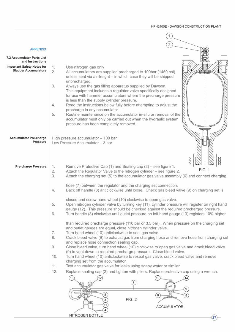
1. Use nitrogen gas only2. All accumulators are supplied precharged to 100bar (1450 psi) unless sent via air-freight – in which case they will be shipped unprecharged.3. Always use the gas filling apparatus supplied by Dawson. This equipment includes a regulator valve specifically designed for use with hammer accumulators where the precharge pressure is less than the supply cylinder pressure.4. Read the instructions below fully before attempting to adjust the precharge in any accumulator5. Routine maintenance on the accumulator in-situ or removal of the accumulator must only be carried out when the hydraulic system pressure has been completely removed.
High pressure accumulator – 100 bar Low Pressure Accumulator – 3 bar
1. Remove Protective Cap (1) and Sealing cap (2) – see figure 1. 2. Attach the Regulator Valve to the nitrogen cylinder – see figure 2.3. Attach the charging set (5) to the accumulator gas valve assembly (6) and connect charging
hose (7) between the regulator and the charging set connection.4. Back off handle (8) anticlockwise until loose. Check gas bleed valve (9) on charging set is
closed and screw hand wheel (10) clockwise to open gas valve.5. Open nitrogen cylinder valve by turning key (11), cylinder pressure will register on right hand gauge (12). This pressure should be checked against the required precharged pressure.6. Turn handle (8) clockwise until outlet pressure on left hand gauge (13) registers 10% higher
than required precharge pressure (110 bar or 3.5 bar). When pressure on the charging set and outlet gauges are equal, close nitrogen cylinder valve.7. Turn hand wheel (10) anticlockwise to seal gas valve.8. Crack bleed valve (9) to exhaust gas from charging hose and remove hose from charging set and replace hose connection sealing cap.9. Close bleed valve, turn hand wheel (10) clockwise to open gas valve and crack bleed valve (9) to vent down to required precharge pressure. Close bleed valve.10. Turn hand wheel (10) anticlockwise to reseal gas valve, crack bleed valve and remove charging set from the accumulator.11. Test accumulator gas valve for leaks using soapy water or similar.12. Replace sealing cap (2) and tighten with pliers. Replace protective cap using a wrench.
FIG. 1
7.2 Accumulator Parts List and Instructions
APPENDIX
FIG. 2
Important Safety Notes for Bladder Accumulators
Accumulator Pre-charge Pressure
Pre-charge Pressure
1
2
NITROGEN BOTTLE
ACCUMULATOR
1313 12
83114
710
6
14
9
5
37
HPH2400E - DAWSON CONSTRUCTION PLANT
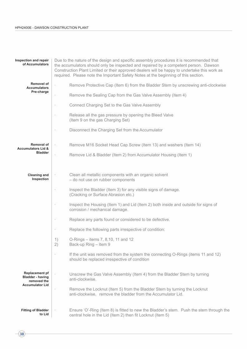
Due to the nature of the design and specific assembly procedures it is recommended that the accumulators should only be inspected and repaired by a competent person. Dawson Construction Plant Limited or their approved dealers will be happy to undertake this work as required. Please note the Important Safety Notes at the beginning of this section.
· Remove Protective Cap (Item 6) from the Bladder Stem by unscrewing anti-clockwise
· Remove the Sealing Cap from the Gas Valve Assembly (Item 4)
· Connect Charging Set to the Gas Valve Assembly
· Release all the gas pressure by opening the Bleed Valve (Item 9 on the gas Charging Set)
· Disconnect the Charging Set from the Accumulator
· Remove M16 Socket Head Cap Screw (Item 13) and washers (Item 14)
· Remove Lid & Bladder (Item 2) from Accumulator Housing (Item 1)
· Clean all metallic components with an organic solvent – do not use on rubber components
· Inspect the Bladder (Item 3) for any visible signs of damage. (Cracking or Surface Abrasion etc.)
· Inspect the Housing (Item 1) and Lid (Item 2) both inside and outside for signs of corrosion / mechanical damage.
· Replace any parts found or considered to be defective.
· Replace the following parts irrespective of condition:
1) O-Rings – items 7, 8,10, 11 and 12 2) Back-up Ring – item 9
· If the unit was removed from the system the connecting O-Rings (items 11 and 12) should be replaced irrespective of condition
· Unscrew the Gas Valve Assembly (Item 4) from the Bladder Stem by turning anti-clockwise.
· Remove the Locknut (Item 5) from the Bladder Stem by turning the Locknut anti-clockwise, remove the bladder from the Accumulator Lid.
· Ensure ‘O’-Ring (Item 8) is fitted to new the Bladder’s stem. Push the stem through the central hole in the Lid (Item 2) then fit Locknut (Item 5)
Inspection and repair of Accumulators
Removel of Accumulators
Pre-charge
Removal of Accumulators Lid &
Bladder
Cleaning and Inspection
Replacement pf Bladder - having
removed the Accumulator Lid
Fitting of Bladder to Lid
38

HPH2400E - DAWSON CONSTRUCTION PLANT
Fitting of Bladder & Lid to Accumulator
Body
· Checking that all O-Rings & Back-up Rings are in Place. Expel all nitrogen from the Bladder (Item 2) to enable it to pass through the top opening in the Housing (Item 1).
· Insert the assembled Bladder & Lid into the Accumulator Housing aligning the holes in the Lid with the M16 tapped holes in the Housing.· Ensure the M16 Socket Head Cap Screws (Items 13) are in good clean condition then install them together with the M16 Nordlock washers (Items 14) into the top of the Housing
· Tighten Items 13 to a torque of 231Nm (173 lbs.ft)
· Re-fit the Gas Valve Assembly (Item 4) and tighten
· Re-fit the Protective Cap (Item 6) and tighten.
Re-Assembly is now complete and the accumulator is ready to be Pre-charged – see details at the top of this section.
PRIOR TO APPLYING HYDRAULIC PRESSURE TO THE SYSTEM THE ACCUMULATOR MUST BE PRECHARGED WITH NITROGEN IN ACCORDANCE WITH THE ABOVE INSTRUCTIONS. FAILURE TO DO SO WILL RESULT IN BLADDER FAILURE.
39
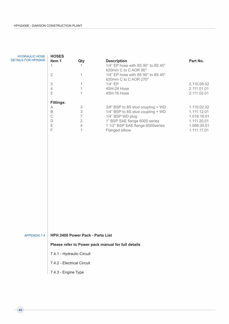
HPH2400E - DAWSON CONSTRUCTION PLANT
HOSESItem 1 Qty Description Part No.1 1 1/4” EP hose with 8S 90° to 8S 45° 620mm C to C AOR 90° 2 1 1/4” EP hose with 8S 90° to 8S 45° 620mm C to C AOR 270°3 1 1/4” EP 2.110.08.02 4 1 4SH-24 Hose 2.111.01.01 5 1 4SH-16 Hose 2.111.02.01
Fittings:A 3 3/8” BSP to 8S stud coupling + WD 1.110.02.02B 3 1/4” BSP to 8S stud coupling + WD 1.111.12.01 C 7 1/4” BSP WD plug 1.018.18.01 D 2 1” BSP SAE flange 6000 series 1.111.20.01 E 4 1 1/2” BSP SAE flange 6000series 1.088.00.01 F 1 Flanged elbow 1.111.17.01
HYDRAULIC HOSE DETAILS FOR HPH2400
HPH 2400 Power Pack - Parts List
Please refer to Power pack manual for full details
7.4.1 - Hydraulic Circuit
7.4.2 - Electrical Circuit
7.4.3 - Engine Type
APPENDIX 7.4
40
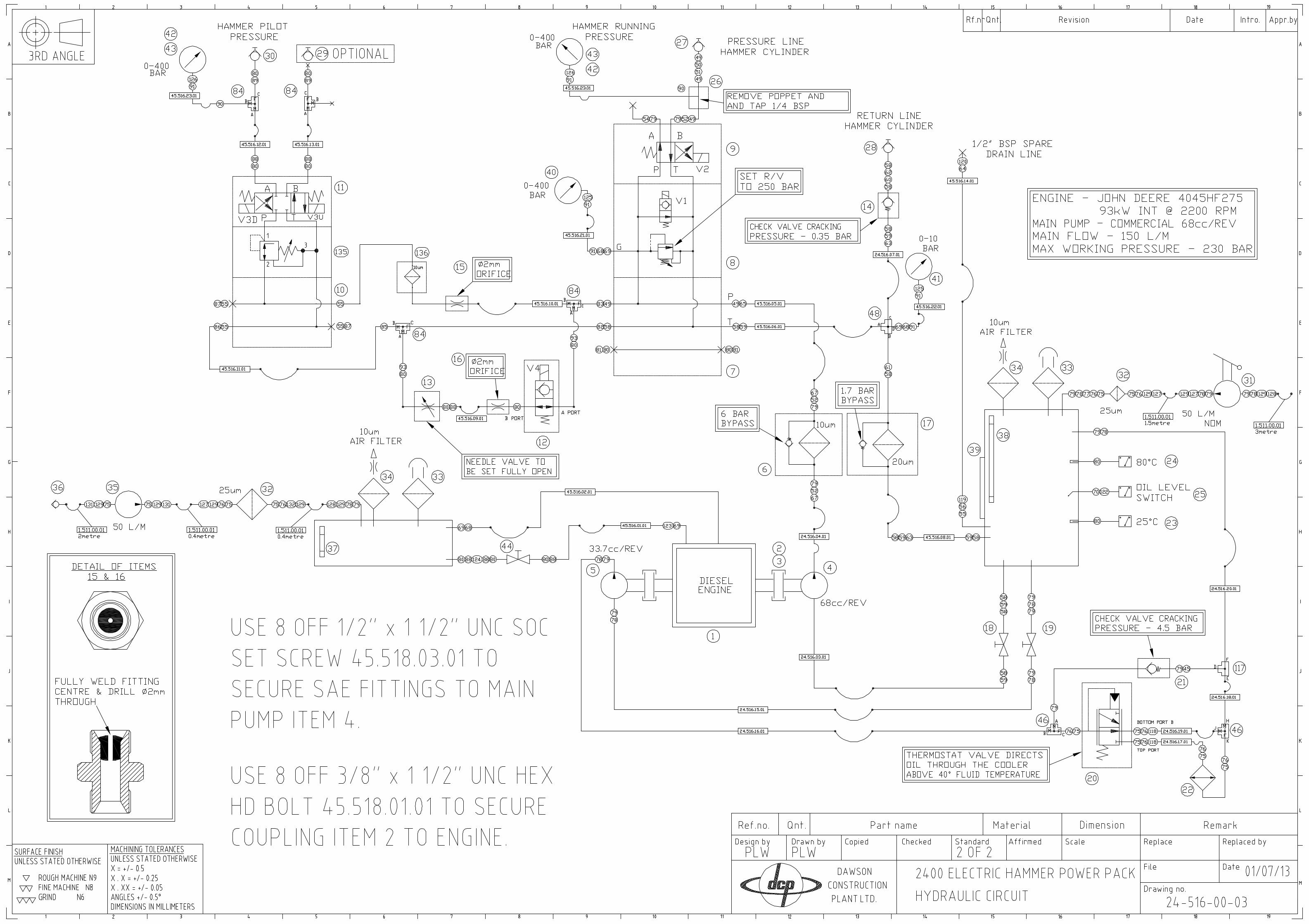
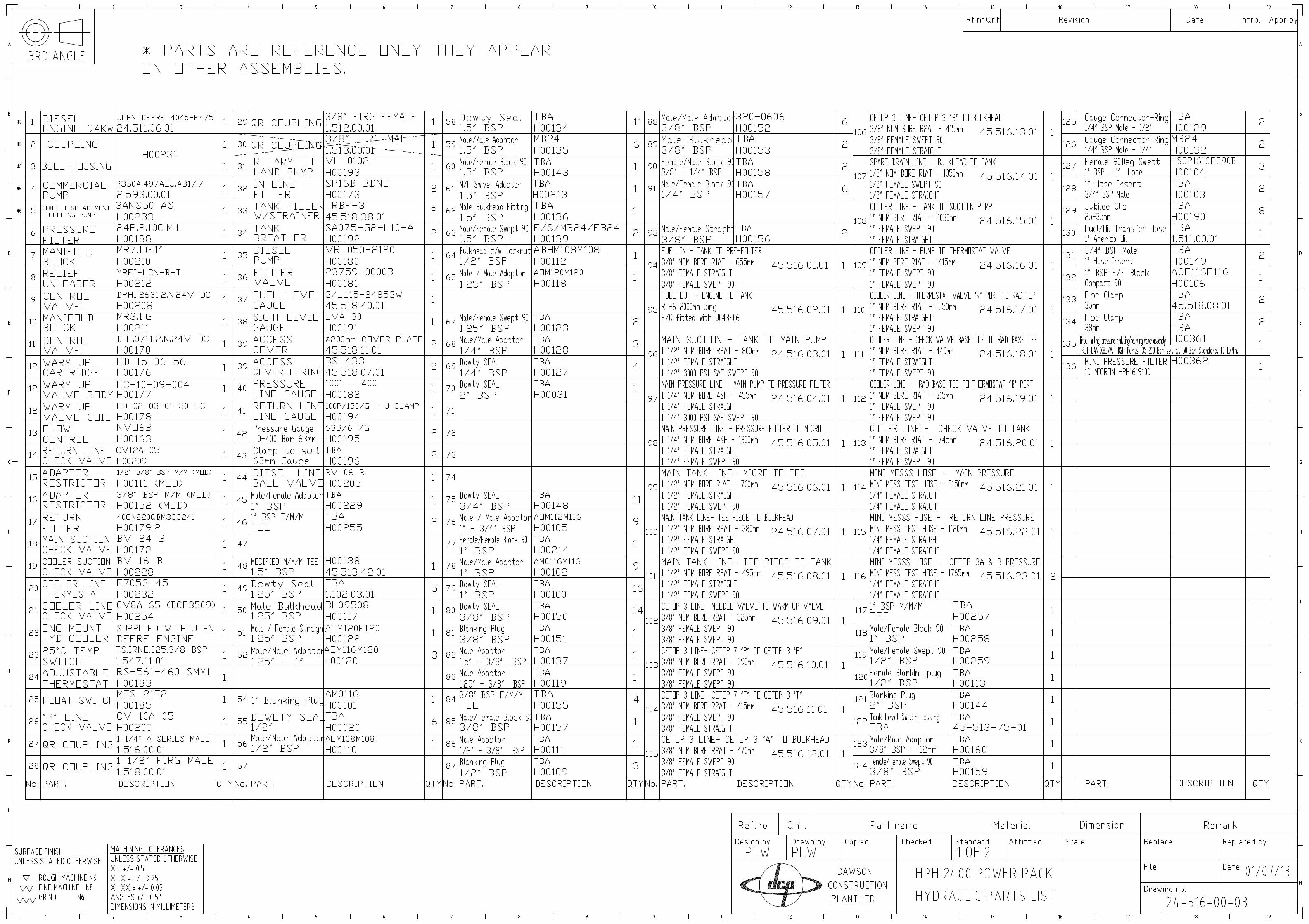
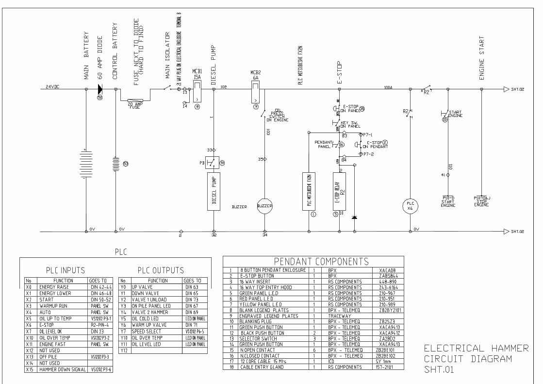
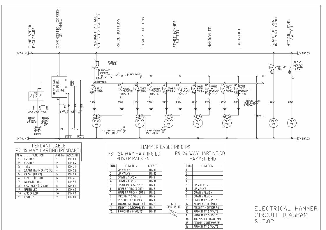
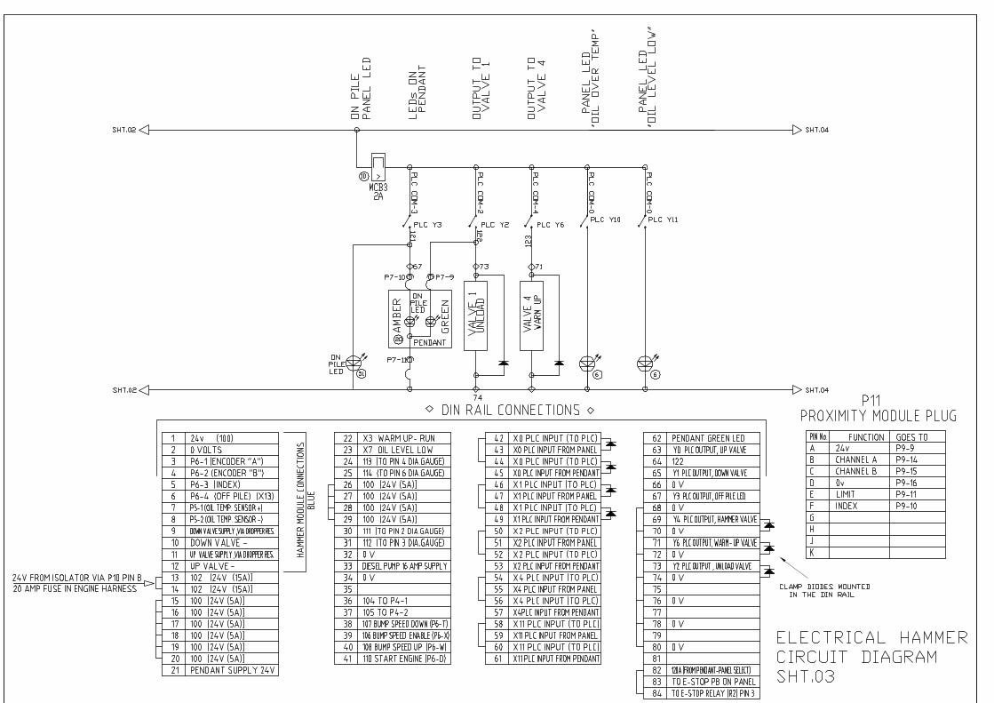
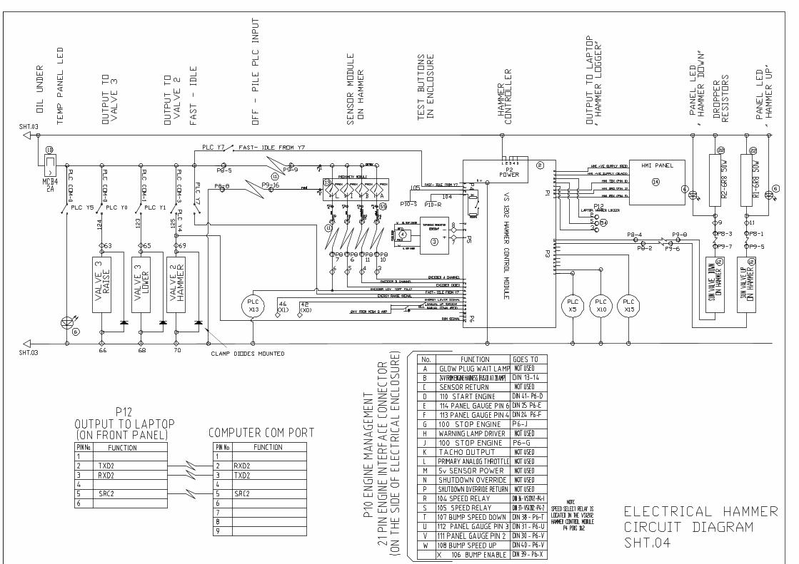
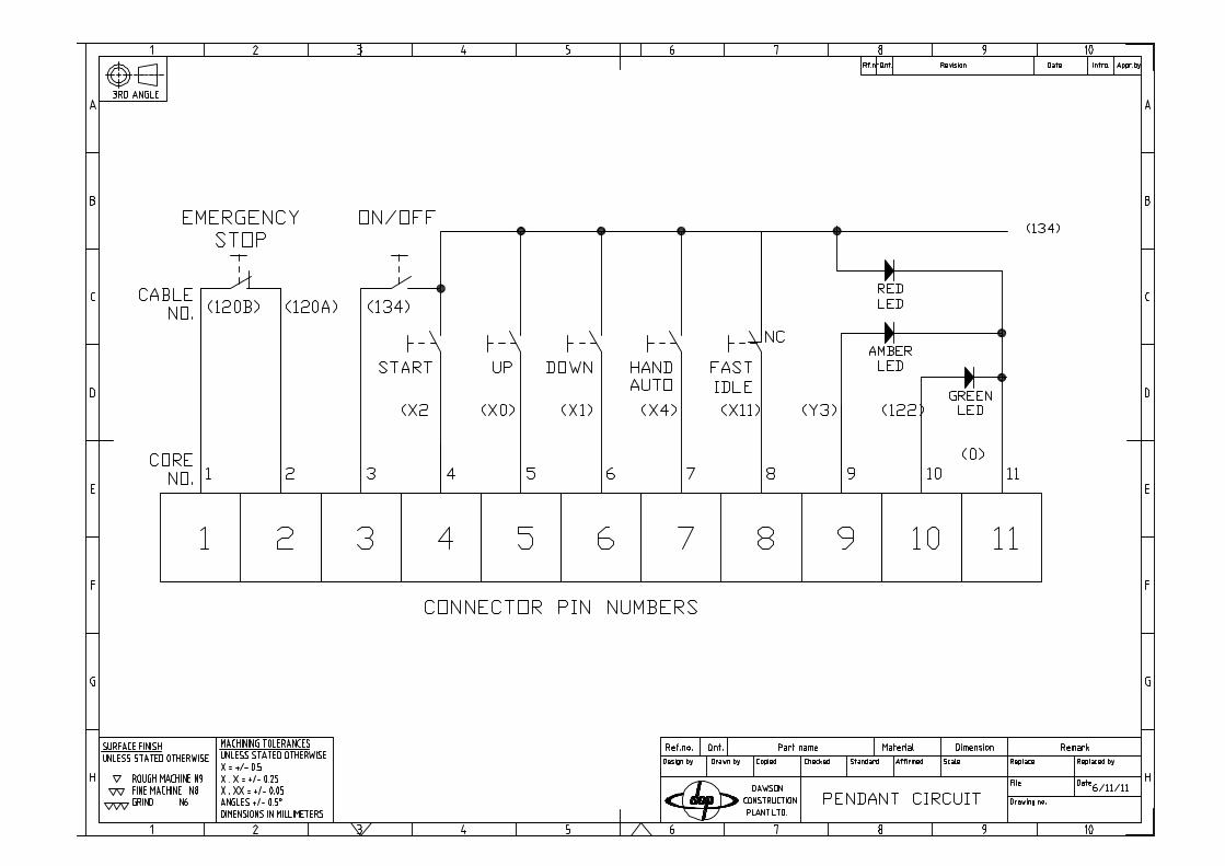
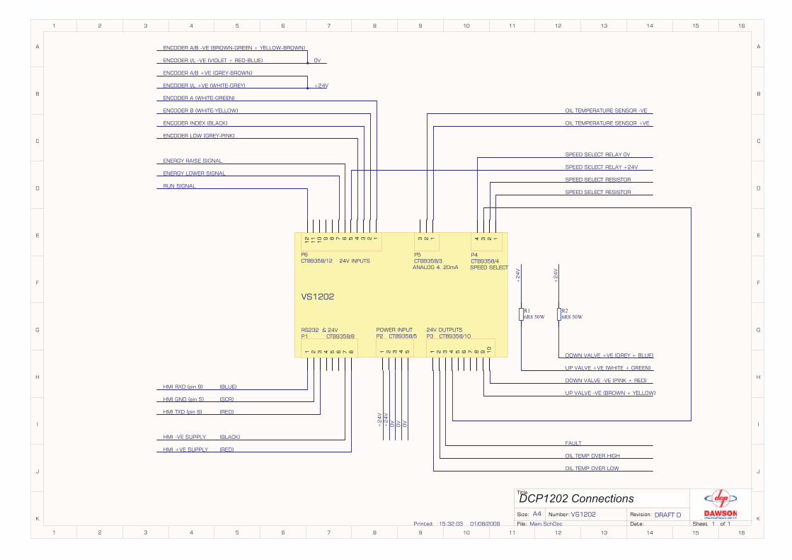
DCP1202 Connections
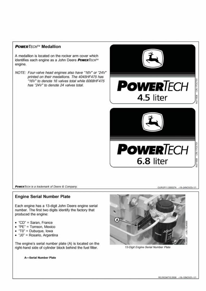
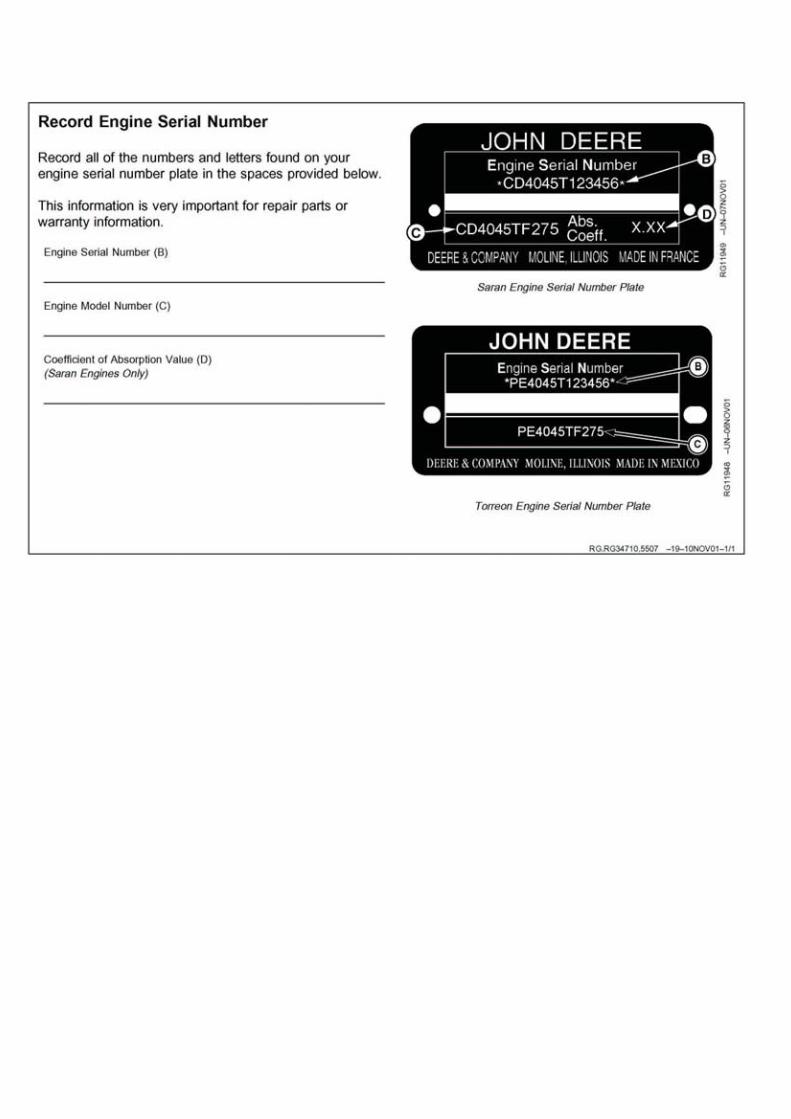
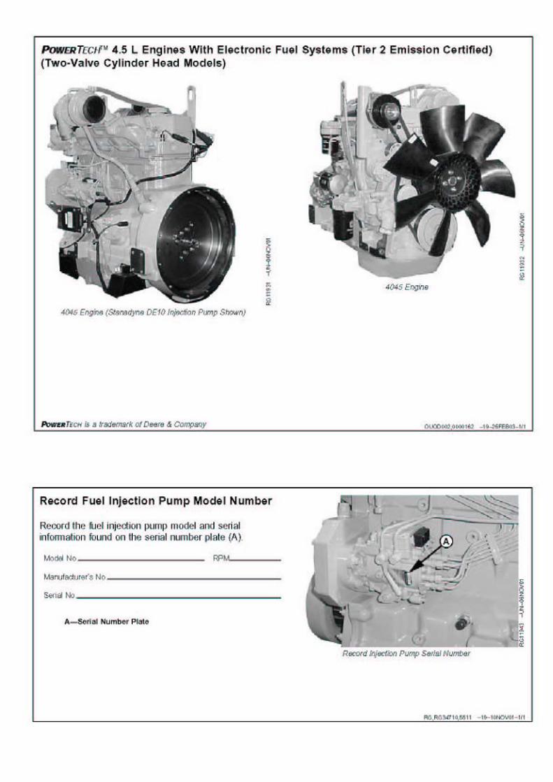
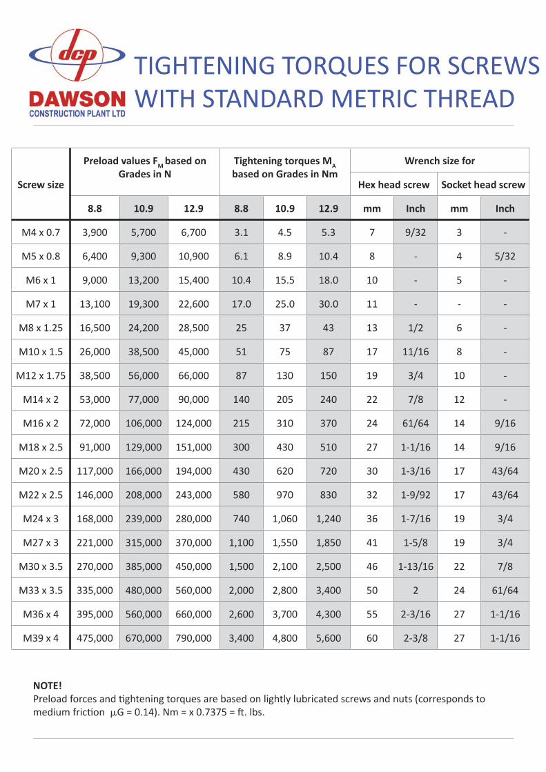
TIGHTENING TORQUES FOR SCREWS WITH STANDARD METRIC THREAD
Screw size
Preload values FM based on Grades in N
Tightening torques MA based on Grades in Nm
Wrench size for
Hex head screw Socket head screw
8.8 10.9 12.9 8.8 10.9 12.9 mm Inch mm Inch
M4 x 0.7 3,900 5,700 6,700 3.1 4.5 5.3 7 9/32 3 -
M5 x 0.8 6,400 9,300 10,900 6.1 8.9 10.4 8 - 4 5/32
M6 x 1 9,000 13,200 15,400 10.4 15.5 18.0 10 - 5 -
M7 x 1 13,100 19,300 22,600 17.0 25.0 30.0 11 - - -
M8 x 1.25 16,500 24,200 28,500 25 37 43 13 1/2 6 -
M10 x 1.5 26,000 38,500 45,000 51 75 87 17 11/16 8 -
M12 x 1.75 38,500 56,000 66,000 87 130 150 19 3/4 10 -
M14 x 2 53,000 77,000 90,000 140 205 240 22 7/8 12 -
M16 x 2 72,000 106,000 124,000 215 310 370 24 61/64 14 9/16
M18 x 2.5 91,000 129,000 151,000 300 430 510 27 1-1/16 14 9/16
M20 x 2.5 117,000 166,000 194,000 430 620 720 30 1-3/16 17 43/64
M22 x 2.5 146,000 208,000 243,000 580 970 830 32 1-9/92 17 43/64
M24 x 3 168,000 239,000 280,000 740 1,060 1,240 36 1-7/16 19 3/4
M27 x 3 221,000 315,000 370,000 1,100 1,550 1,850 41 1-5/8 19 3/4
M30 x 3.5 270,000 385,000 450,000 1,500 2,100 2,500 46 1-13/16 22 7/8
M33 x 3.5 335,000 480,000 560,000 2,000 2,800 3,400 50 2 24 61/64
M36 x 4 395,000 560,000 660,000 2,600 3,700 4,300 55 2-3/16 27 1-1/16
M39 x 4 475,000 670,000 790,000 3,400 4,800 5,600 60 2-3/8 27 1-1/16
NOTE!Preload forces and �ghtening torques are based on lightly lubricated screws and nuts (corresponds to medium fric�on G = 0.14). Nm = x 0.7375 = �. lbs.
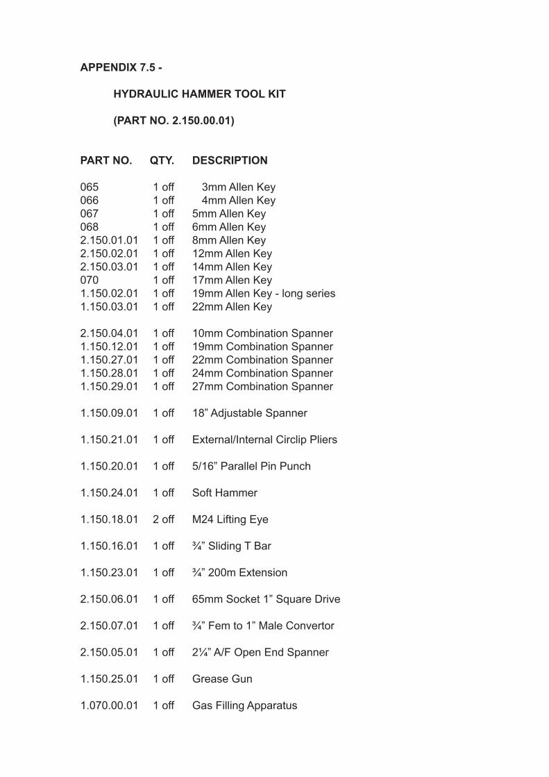
APPENDIX 7.5 -
HYDRAULIC HAMMER TOOL KIT
(PART NO. 2.150.00.01)
PART NO. QTY. DESCRIPTION
065 1 off 3mm Allen Key066 1 off 4mm Allen Key067 1 off 5mm Allen Key 068 1 off 6mm Allen Key2.150.01.01 1 off 8mm Allen Key2.150.02.01 1 off 12mm Allen Key2.150.03.01 1 off 14mm Allen Key070 1 off 17mm Allen Key1.150.02.01 1 off 19mm Allen Key - long series1.150.03.01 1 off 22mm Allen Key
2.150.04.01 1 off 10mm Combination Spanner1.150.12.01 1 off 19mm Combination Spanner1.150.27.01 1 off 22mm Combination Spanner1.150.28.01 1 off 24mm Combination Spanner1.150.29.01 1 off 27mm Combination Spanner
1.150.09.01 1 off 18” Adjustable Spanner
1.150.21.01 1 off External/Internal Circlip Pliers
1.150.20.01 1 off 5/16” Parallel Pin Punch
1.150.24.01 1 off Soft Hammer
1.150.18.01 2 off M24 Lifting Eye
1.150.16.01 1 off ¾” Sliding T Bar
1.150.23.01 1 off ¾” 200m Extension
2.150.06.01 1 off 65mm Socket 1” Square Drive
2.150.07.01 1 off ¾” Fem to 1” Male Convertor
2.150.05.01 1 off 2¼” A/F Open End Spanner
1.150.25.01 1 off Grease Gun
1.070.00.01 1 off Gas Filling Apparatus
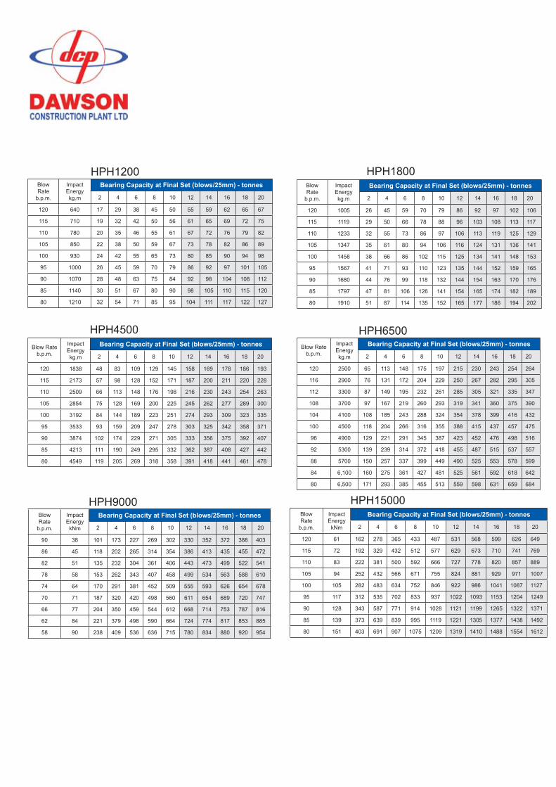
Blow Rateb.p.m.
ImpactEnergy kg.m
Bearing Capacity at Final Set (blows/25mm) - tonnes
2 4 6 8 10 12 14 16 18 20
120 1838 48 83 109 129 145 158 169 178 186 193
115 2173 57 98 128 152 171 187 200 211 220 228
110 2509 66 113 148 176 198 216 230 243 254 263
105 2854 75 128 169 200 225 245 262 277 289 300
100 3192 84 144 189 223 251 274 293 309 323 335
95 3533 93 159 209 247 278 303 325 342 358 371
90 3874 102 174 229 271 305 333 356 375 392 407
85 4213 111 190 249 295 332 362 387 408 427 442
80 4549 119 205 269 318 358 391 418 441 461 478
HPH4500Blow Rate
b.p.m.
ImpactEnergy kg.m
Bearing Capacity at Final Set (blows/25mm) - tonnes
2 4 6 8 10 12 14 16 18 20
120 2500 65 113 148 175 197 215 230 243 254 264
116 2900 76 131 172 204 229 250 267 282 295 305
112 3300 87 149 195 232 261 285 305 321 335 347
108 3700 97 167 219 260 293 319 341 360 375 390
104 4100 108 185 243 288 324 354 378 399 416 432
100 4500 118 204 266 316 355 388 415 437 457 475
96 4900 129 221 291 345 387 423 452 476 498 516
92 5300 139 239 314 372 418 455 487 515 537 557
88 5700 150 257 337 399 449 490 525 553 578 599
84 6,100 160 275 361 427 481 525 561 592 618 642
80 6,500 171 293 385 455 513 559 598 631 659 684
HPH6500
Blow Rate
b.p.m.
ImpactEnergy
kNm
Bearing Capacity at Final Set (blows/25mm) - tonnes
2 4 6 8 10 12 14 16 18 20
90 38 101 173 227 269 302 330 352 372 388 403
86 45 118 202 265 314 354 386 413 435 455 472
82 51 135 232 304 361 406 443 473 499 522 541
78 58 153 262 343 407 458 499 534 563 588 610
74 64 170 291 381 452 509 555 593 626 654 678
70 71 187 320 420 498 560 611 654 689 720 747
66 77 204 350 459 544 612 668 714 753 787 816
62 84 221 379 498 590 664 724 774 817 853 885
58 90 238 409 536 636 715 780 834 880 920 954
HPH9000Blow Rate
b.p.m.
ImpactEnergy
kNm
Bearing Capacity at Final Set (blows/25mm) - tonnes
2 4 6 8 10 12 14 16 18 20
120 61 162 278 365 433 487 531 568 599 626 649
115 72 192 329 432 512 577 629 673 710 741 769
110 83 222 381 500 592 666 727 778 820 857 889
105 94 252 432 566 671 755 824 881 929 971 1007
100 105 282 483 634 752 846 922 986 1041 1087 1127
95 117 312 535 702 833 937 1022 1093 1153 1204 1249
90 128 343 587 771 914 1028 1121 1199 1265 1322 1371
85 139 373 639 839 995 1119 1221 1305 1377 1438 1492
80 151 403 691 907 1075 1209 1319 1410 1488 1554 1612
HPH15000
Blow Rate
b.p.m.
ImpactEnergy kg.m
Bearing Capacity at Final Set (blows/25mm) - tonnes
2 4 6 8 10 12 14 16 18 20
120 640 17 29 38 45 50 55 59 62 65 67
115 710 19 32 42 50 56 61 65 69 72 75
110 780 20 35 46 55 61 67 72 76 79 82
105 850 22 38 50 59 67 73 78 82 86 89
100 930 24 42 55 65 73 80 85 90 94 98
95 1000 26 45 59 70 79 86 92 97 101 105
90 1070 28 48 63 75 84 92 98 104 108 112
85 1140 30 51 67 80 90 98 105 110 115 120
80 1210 32 54 71 85 95 104 111 117 122 127
HPH1200Blow Rate
b.p.m.
ImpactEnergy kg.m
Bearing Capacity at Final Set (blows/25mm) - tonnes
2 4 6 8 10 12 14 16 18 20
120 1005 26 45 59 70 79 86 92 97 102 106
115 1119 29 50 66 78 88 96 103 108 113 117
110 1233 32 55 73 86 97 106 113 119 125 129
105 1347 35 61 80 94 106 116 124 131 136 141
100 1458 38 66 86 102 115 125 134 141 148 153
95 1567 41 71 93 110 123 135 144 152 159 165
90 1680 44 76 99 118 132 144 154 163 170 176
85 1797 47 81 106 126 141 154 165 174 182 189
80 1910 51 87 114 135 152 165 177 186 194 202
HPH1800
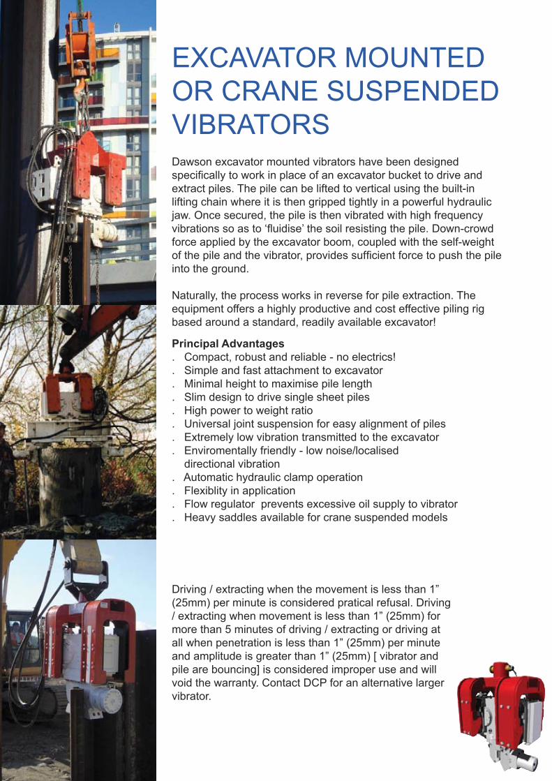
EXCAVATOR MOUNTED OR CRANE SUSPENDED VIBRATORS
Driving / extracting when the movement is less than 1” (25mm) per minute is considered pratical refusal. Driving / extracting when movement is less than 1” (25mm) for more than 5 minutes of driving / extracting or driving at all when penetration is less than 1” (25mm) per minute and amplitude is greater than 1” (25mm) [ vibrator and pile are bouncing] is considered improper use and will void the warranty. Contact DCP for an alternative larger vibrator.
Principal Advantages. Compact, robust and reliable - no electrics!. Simple and fast attachment to excavator. Minimal height to maximise pile length. Slim design to drive single sheet piles. High power to weight ratio. Universal joint suspension for easy alignment of piles. Extremely low vibration transmitted to the excavator. Enviromentally friendly - low noise/localised directional vibration. Automatic hydraulic clamp operation. Flexiblity in application. Flow regulator prevents excessive oil supply to vibrator. Heavy saddles available for crane suspended models
Dawson excavator mounted vibrators have been designed specifically to work in place of an excavator bucket to drive and extract piles. The pile can be lifted to vertical using the built-in lifting chain where it is then gripped tightly in a powerful hydraulic jaw. Once secured, the pile is then vibrated with high frequency vibrations so as to ‘fluidise’ the soil resisting the pile. Down-crowd force applied by the excavator boom, coupled with the self-weight of the pile and the vibrator, provides sufficient force to push the pile into the ground.
Naturally, the process works in reverse for pile extraction. The equipment offers a highly productive and cost effective piling rig based around a standard, readily available excavator!
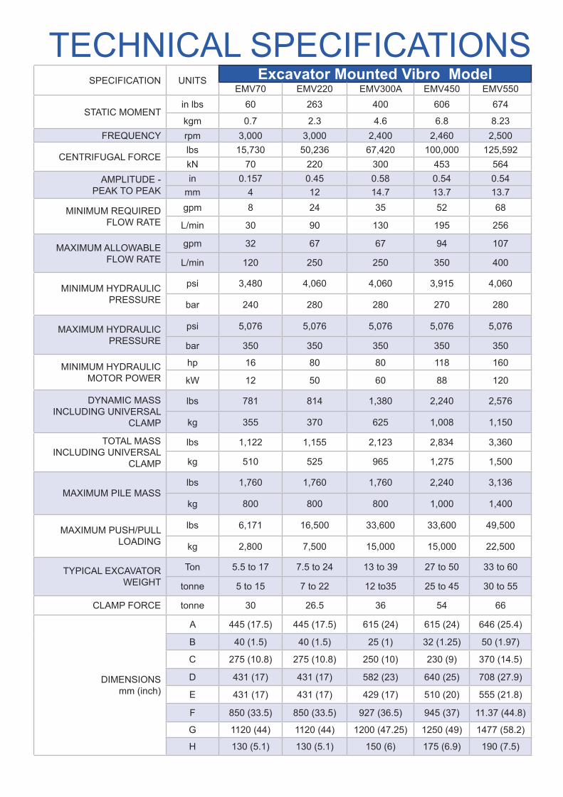
SPECIFICATION UNITS Excavator Mounted Vibro ModelEMV70 EMV220 EMV300A EMV450 EMV550
STATIC MOMENTin lbs 60 263 400 606 674
kgm 0.7 2.3 4.6 6.8 8.23FREQUENCY rpm 3,000 3,000 2,400 2,460 2,500
CENTRIFUGAL FORCElbs 15,730 50,236 67,420 100,000 125,592kN 70 220 300 453 564
AMPLITUDE - PEAK TO PEAK
in 0.157 0.45 0.58 0.54 0.54mm 4 12 14.7 13.7 13.7
MINIMUM REQUIRED FLOW RATE
gpm 8 24 35 52 68
L/min 30 90 130 195 256
MAXIMUM ALLOWABLEFLOW RATE
gpm 32 67 67 94 107
L/min 120 250 250 350 400
MINIMUM HYDRAULICPRESSURE
psi 3,480 4,060 4,060 3,915 4,060
bar 240 280 280 270 280
MAXIMUM HYDRAULICPRESSURE
psi 5,076 5,076 5,076 5,076 5,076
bar 350 350 350 350 350
MINIMUM HYDRAULICMOTOR POWER
hp 16 80 80 118 160
kW 12 50 60 88 120
DYNAMIC MASS INCLUDING UNIVERSAL
CLAMP
lbs 781 814 1,380 2,240 2,576
kg 355 370 625 1,008 1,150
TOTAL MASSINCLUDING UNIVERSAL
CLAMP
lbs 1,122 1,155 2,123 2,834 3,360
kg 510 525 965 1,275 1,500
MAXIMUM PILE MASSlbs 1,760 1,760 1,760 2,240 3,136
kg 800 800 800 1,000 1,400
MAXIMUM PUSH/PULLLOADING
lbs 6,171 16,500 33,600 33,600 49,500
kg 2,800 7,500 15,000 15,000 22,500
TYPICAL EXCAVATORWEIGHT
Ton 5.5 to 17 7.5 to 24 13 to 39 27 to 50 33 to 60
tonne 5 to 15 7 to 22 12 to35 25 to 45 30 to 55
CLAMP FORCE tonne 30 26.5 36 54 66
DIMENSIONSmm (inch)
A 445 (17.5) 445 (17.5) 615 (24) 615 (24) 646 (25.4)
B 40 (1.5) 40 (1.5) 25 (1) 32 (1.25) 50 (1.97)
C 275 (10.8) 275 (10.8) 250 (10) 230 (9) 370 (14.5)
D 431 (17) 431 (17) 582 (23) 640 (25) 708 (27.9)
E 431 (17) 431 (17) 429 (17) 510 (20) 555 (21.8)
F 850 (33.5) 850 (33.5) 927 (36.5) 945 (37) 11.37 (44.8)
G 1120 (44) 1120 (44) 1200 (47.25) 1250 (49) 1477 (58.2)
H 130 (5.1) 130 (5.1) 150 (6) 175 (6.9) 190 (7.5)
TECHNICAL SPECIFICATIONS
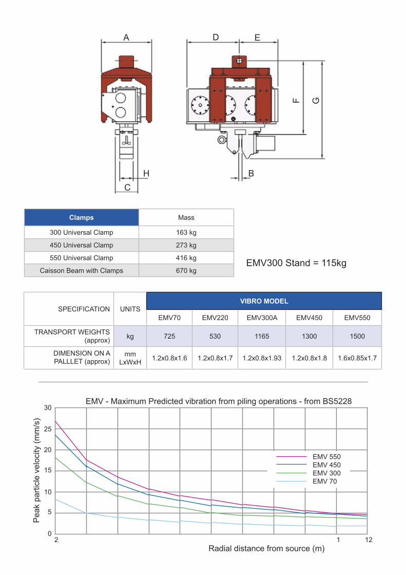
EDA
F G
HC
B
EMV300 Stand = 115kg
2 � 1 12
25
20
15
10
5
0
Radial distance from source (m)
Pea
k pa
rticl
e ve
loci
ty (m
m/s
)
EMV - Maximum Predicted vibration from piling operations - from BS5228
EMV 550EMV 450EMV 300EMV 70
30
Clamps Mass
300 Universal Clamp 163 kg
450 Universal Clamp 273 kg
550 Universal Clamp 416 kg
Caisson Beam with Clamps 670 kg
SPECIFICATION UNITSVIBRO MODEL
EMV70 EMV220 EMV300A EMV450 EMV550
TRANSPORT WEIGHTS(approx) kg 725 530 1165 1300 1500
DIMENSION ON A PALLLET (approx)
mmLxWxH 1.2x0.8x1.6 1.2x0.8x1.7 1.2x0.8x1.93 1.2x0.8x1.8 1.6x0.85x1.7
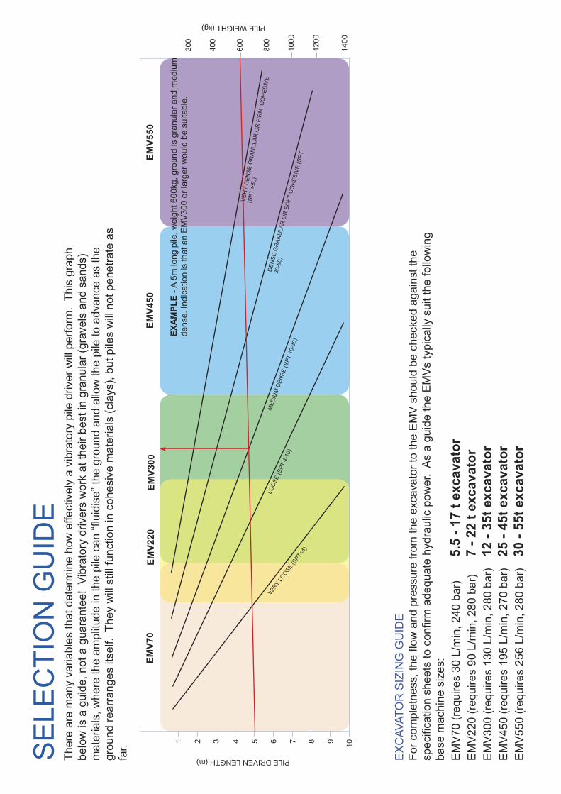
SE
LEC
TIO
N G
UID
ETh
ere
are
man
y va
riabl
es th
at d
eter
min
e ho
w e
ffect
ivel
y a
vibr
ator
y pi
le d
river
will
per
form
. Th
is g
raph
be
low
is a
gui
de, n
ot a
gua
rant
ee!
Vibr
ator
y dr
iver
s w
ork
at th
eir b
est i
n gr
anul
ar (g
rave
ls a
nd s
ands
) m
ater
ials
, whe
re th
e am
plitu
de in
the
pile
can
“flui
dise
” the
gro
und
and
allo
w th
e pi
le to
adv
ance
as
the
grou
nd re
arra
nges
itse
lf. T
hey
will
stil
l fun
ctio
n in
coh
esiv
e m
ater
ials
(cla
ys),
but p
iles
will
not
pen
etra
te a
s fa
r.
EX
CAV
ATO
R S
IZIN
G G
UID
EFo
r com
plet
ness
, the
flow
and
pre
ssur
e fro
m th
e ex
cava
tor t
o th
e E
MV
sho
uld
be c
heck
ed a
gain
st th
e sp
ecifi
catio
n sh
eets
to c
onfir
m a
dequ
ate
hydr
aulic
pow
er.
As
a gu
ide
the
EM
Vs
typi
cally
sui
t the
follo
win
g ba
se m
achi
ne s
izes
:E
MV
70 (r
equi
res
30 L
/min
, 240
bar
) 5.
5 - 1
7 t e
xcav
ator
E
MV
220
(req
uire
s 90
L/m
in, 2
80 b
ar)
7 - 2
2 t e
xcav
ator
EM
V30
0 (r
equi
res
130
L/m
in, 2
80 b
ar)
12 -
35t e
xcav
ator
EM
V45
0 (r
equi
res
195
L/m
in, 2
70 b
ar)
25 -
45t e
xcav
ator
EM
V55
0 (r
equi
res
256
L/m
in, 2
80 b
ar)
30 -
55t e
xcav
ator
EMV7
0EM
V300
EMV4
50EM
V550
1 2 3 4 5 6 7 8 9 10
PILE DRIVEN LENGTH (m)
EXA
MPL
E - A
5m
long
pile
, wei
ght 6
00kg
, gro
und
is g
ranu
lar a
nd m
ediu
m
dens
e. In
dica
tion
is th
at a
n E
MV
300
or la
rger
wou
ld b
e su
itabl
e.
1400
1200
1000
800
600
400
200
VERY
LOOSE
(SPT
<4)
LOO
SE (S
PT 4
-10)
MED
IUM
DEN
SE (S
PT 1
0-30
)
DEN
SE G
RAN
ULA
R O
R S
OFT
CO
HES
IVE
(SPT
30-5
0)
VER
Y D
ENSE
GR
ANU
LAR
OR
FIR
M C
OH
ESIV
E
(SPT
>50
)
PILE WEIGHT (kg)
EMV2
20
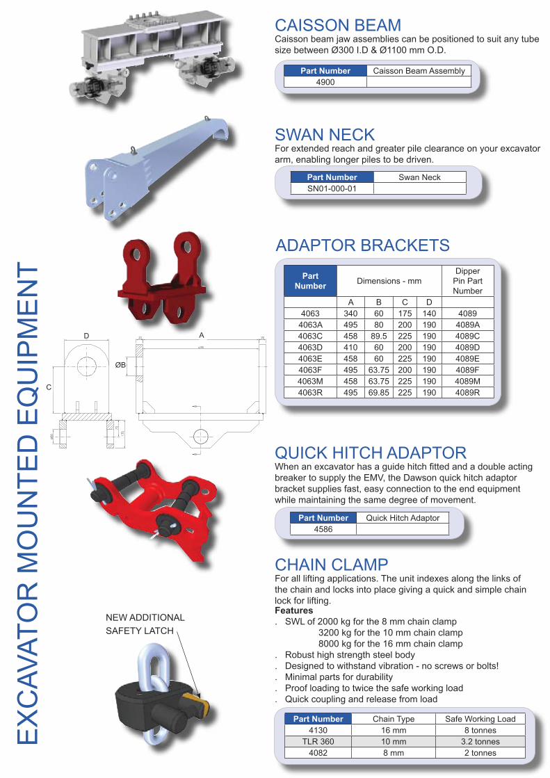
Part Number Quick Hitch Adaptor4586
QUICK HITCH ADAPTORWhen an excavator has a guide hitch fitted and a double acting breaker to supply the EMV, the Dawson quick hitch adaptor bracket supplies fast, easy connection to the end equipment while maintaining the same degree of movement.
Part Number Swan NeckSN01-000-01
SWAN NECKFor extended reach and greater pile clearance on your excavator arm, enabling longer piles to be driven.
CHAIN CLAMP For all lifting applications. The unit indexes along the links of the chain and locks into place giving a quick and simple chain lock for lifting.
Part Number Chain Type Safe Working Load4130 16 mm 8 tonnes
TLR 360 10 mm 3.2 tonnes4082 8 mm 2 tonnes
Features. SWL of 2000 kg for the 8 mm chain clamp 3200 kg for the 10 mm chain clamp 8000 kg for the 16 mm chain clamp. Robust high strength steel body. Designed to withstand vibration - no screws or bolts!. Minimal parts for durability. Proof loading to twice the safe working load. Quick coupling and release from load
NEW ADDITIONAL SAFETY LATCH
Part Number Caisson Beam Assembly4900
CAISSON BEAMCaisson beam jaw assemblies can be positioned to suit any tube size between Ø300 I.D & Ø1100 mm O.D.
Part Number Dimensions - mm
Dipper Pin Part Number
A B C D4063 340 60 175 140 4089
4063A 495 80 200 190 4089A4063C 458 89.5 225 190 4089C4063D 410 60 200 190 4089D4063E 458 60 225 190 4089E4063F 495 63.75 200 190 4089F4063M 458 63.75 225 190 4089M4063R 495 69.85 225 190 4089R
ADAPTOR BRACKETS
EX
CAV
ATO
R M
OU
NTE
D E
QU
IPM
EN
T
A
ØB
C
D
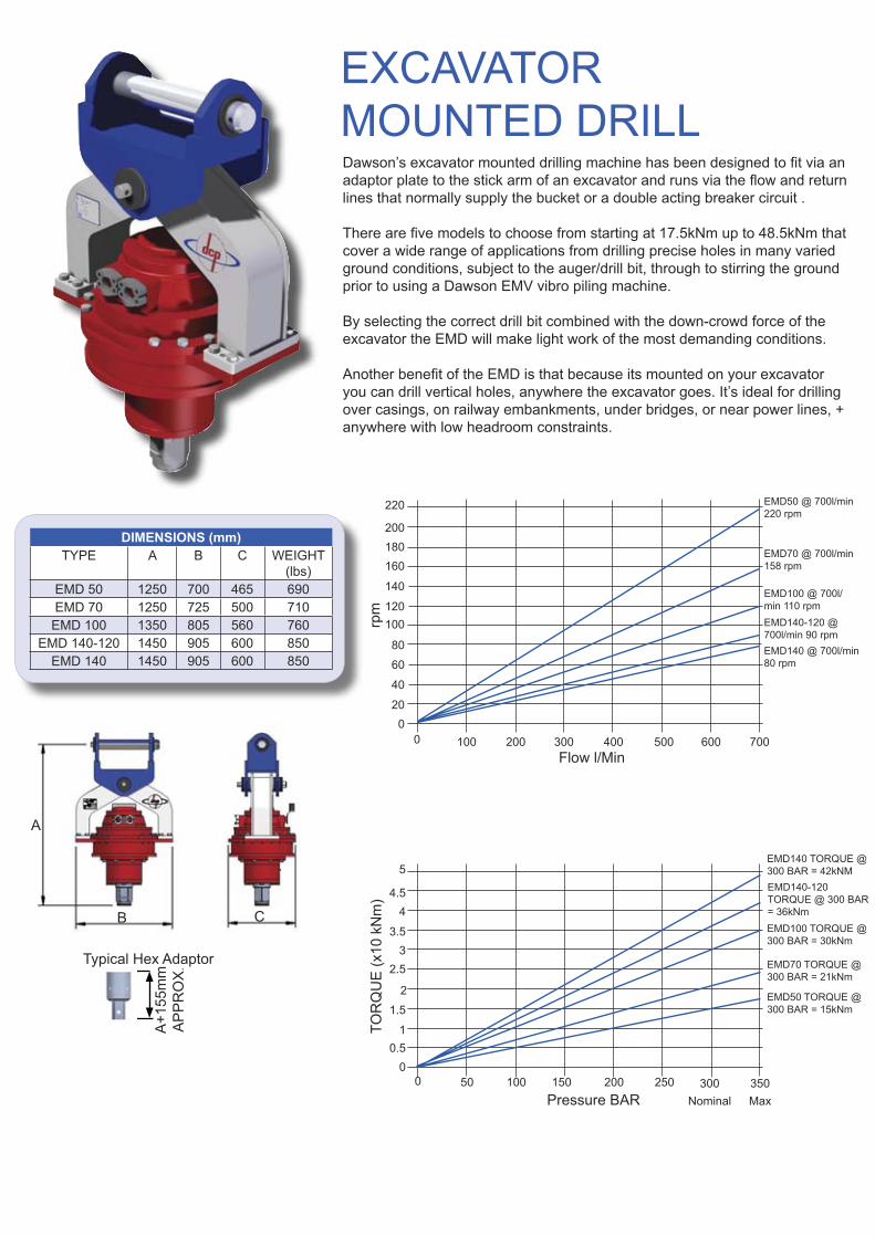
A
CB
Dawson’s excavator mounted drilling machine has been designed to fit via an adaptor plate to the stick arm of an excavator and runs via the flow and return lines that normally supply the bucket or a double acting breaker circuit .
There are five models to choose from starting at 17.5kNm up to 48.5kNm that cover a wide range of applications from drilling precise holes in many varied ground conditions, subject to the auger/drill bit, through to stirring the ground prior to using a Dawson EMV vibro piling machine.
By selecting the correct drill bit combined with the down-crowd force of the excavator the EMD will make light work of the most demanding conditions.
Another benefit of the EMD is that because its mounted on your excavator you can drill vertical holes, anywhere the excavator goes. It’s ideal for drilling over casings, on railway embankments, under bridges, or near power lines, + anywhere with low headroom constraints.
EXCAVATOR MOUNTED DRILL
DIMENSIONS (mm)TYPE A B C WEIGHT
(lbs) EMD 50 1250 700 465 690EMD 70 1250 725 500 710
EMD 100 1350 805 560 760EMD 140-120 1450 905 600 850
EMD 140 1450 905 600 850
0 50 100 150 200 250 300Nominal
350Max
EMD140 TORQUE @300 BAR = 42kNMEMD140-120 TORQUE @ 300 BAR = 36kNmEMD100 TORQUE @ 300 BAR = 30kNm
EMD70 TORQUE @ 300 BAR = 21kNm
EMD50 TORQUE @ 300 BAR = 15kNm
00.5
1
1.5
2
2.53
3.5
4 4.5
5
Pressure BAR
TOR
QU
E (x
10 k
Nm
)
0 100 200 300 400 500 600 7000
20
40
60
80
100120
140
160180200
220 EMD50 @ 700l/min220 rpm
EMD70 @ 700l/min158 rpm
EMD100 @ 700l/min 110 rpmEMD140-120 @ 700l/min 90 rpmEMD140 @ 700l/min80 rpm
Flow l/Min
rpm
Typical Hex Adaptor
A+1
55m
mA
PP
RO
X.

D.C.P. RESERVES THE RIGHT TO DISCONTINUE EQUIPMENT AT ANY TIME, OR CHANGE SPECIFICATIONS OR DESIGNS WITHOUT NOTICE OR INCURRING OBLIGATIONS
Rev.H24E-02
Dawson Construction Plant LtdChesney Wold.Bleak Hall,Milton Keynes,MK6 1NE, EnglandTel: +44 (0) 1908 240300Fax: +44 (0) 1908 240222
HPH2400EHYDRAULIC HAMMER