Embed Size (px)
Citation preview
OPERATION ANDMAINTENANCE MANUAL
HPS® IntegratedLoPro Valve (ILP)

HPS® Integrated LoPro valve
HPS® IntegratedLoPro Valve (ILP)
January 2002Part #100012201
HPS® Integrated LoPro valve
Part #
Please fill in these numbers and have themreadily available when calling or service oradditional information.
(The part number can be found on your packingslip, and both the port number serial number arelocated on the side of the housing.)
For more information or literature, contact:
MKS Instruments, Inc. HPS® Products5330 sterling driveBoulder, CO 80301 USA
Phone: 303-449-9861800-345-1967
Fax: 303-442-6880
HPS® Integrated LoPro valve
Table of Contents
1. IN THIS MANUAL ............................................................. 1
2. DESCRIPTION OF INTEGRATED LOPRO SERIESVALVES ................................................................................ 2
3. SAFETY PROCEDURES AND PRECAUTIONS .............. 3
3.1 Modification .............................................................................. 33.2 Maintenance ............................................................................. 33.3 Hazardous Materials ................................................................ 33.4 Installation ................................................................................ 33.5 Operation .................................................................................. 3
4. OPERATING PRINCIPLES .............................................. 4
4.1 Pneumatic Cycling .................................................................... 44.2 Limit Switch Actuation .............................................................. 54.3 Solenoid Operated Pilot Valve Operation ................................. 64.4 Heaters ...................................................................................... 7
5. SPECIFICATIONS ............................................................ 9
5.1 Environment ............................................................................... 95.1.1 Installation Orientation ...................................................... 9
5.1.2 Applied Forces ......................................................................... 95.1.3 Temperature Extremes ...................................................... 9
5.2 Operation & Performance ....................................................... 105.2.1 Cycle Rate and Life ......................................................... 105.2.2 System Pressure Limits .................................................. 105.2.3 Pneumatic Pressure Limits ............................................. 115.2.4 Pneumatic Flow .............................................................. 115.2.5 Limit Switch Ratings ........................................................ 115.2.6 Solenoid Duty Cycle and Power Requirements .............. 11
5.3 Physical Parameters ................................................................. 115.3.1 Dimensions ..................................................................... 115.3.2 Weight ............................................................................. 13
6. INSTALLATION INFORMATION ..................................... 14
6.1 Pneumatic Supply .................................................................. 146.2 Electrical Connections ............................................................ 146.3 Clean Installations .................................................................. 146.4 Flange Care ............................................................................ 15
Table of Contents
HPS® Integrated LoPro valve
7. SERVICE ........................................................................ 16
7.1 Removal from System .............................................................. 167.2 Actuator Assembly.................................................................. 17
7.2.1 Actuator Assembly Removal and Disassembly .............. 177.2.2 O-ring Replacement ........................................................ 177.2.3 Actuator Assembly Installation ........................................ 18
7.3 Solenoid Pilot Valve Service ..................................................... 197.4 Replacement Parts List ............................................................ 20
8. TROUBLE SHOOTING .................................................. 21
8.1 PROBLEMS AND DIAGNOSES ............................................... 228.1.1 Won’t close completely ................................................... 228.1.2 Won’t open completely .................................................... 228.1.3 Opens slowly or in jumps ................................................ 228.1.4 Won’t open at all ............................................................. 228.1.5 Squeaks when opening and/or closing ........................... 238.1.6 Leaks across closed nosepiece seal .............................. 238.1.7 Leaks from atmosphere when closed ............................. 238.1.8 Leaks from atmosphere when open ............................... 238.1.9 Leaks from atmosphere at all times ................................ 238.1.10 Air leaks from around piston when open ...................... 238.1.11 Air leaks from vent hole while operating ....................... 248.1.12 Air leaks from vent hole when open .............................. 248.1.13 Limit switches don’t send signal ................................... 248.1.14 Solenoid valve buzzes or doesn’t work ......................... 248.1.15 Air leaking from non-actuated port or solenoid ............ 24
8.2 CAUSES AND REMEDIES ....................................................... 248.2.1 Spring failure ................................................................... 248.2.2 Stem weld failure ............................................................. 248.2.3 Body damage .................................................................. 248.2.4 Port flange damage......................................................... 258.2.5 Particulates, condensation, and corrosion ...................... 258.2.6 Bellows failure ................................................................. 258.2.7 Nosepiece seal failure ..................................................... 258.2.8 Bonnet seal Failure ......................................................... 268.2.9 Piston seal failure ............................................................ 268.2.10 Stem seal failure ........................................................... 268.2.11 Bonnet seal omission .................................................... 268.2.12 Nosepiece seal omission .............................................. 268.2.13 Improper assembly ....................................................... 268.2.14 Loose piston .................................................................. 268.2.15 Inadequate lubrication .................................................. 278.2.16 Inadequate air pressure ................................................ 278.2.17 Inadequate air flow........................................................ 278.2.18 Limit switch failure ........................................................ 278.2.19 Solenoid valve failure .................................................... 278.2.20 Dynamic bypass seal failure ......................................... 28
HPS® Integrated LoPro valve
9 RETURN TO FACTORY FOR REPAIR OR SERVICES .. 29
9.2 Call the factory ......................................................................... 299.3 Prepare for shipment ................................................................ 299.4 Payment .................................................................................... 29
10 WARRANTY .................................................................. 30
10.1 Coverage .............................................................................. 3010.2 WARRANTY PERFORMANCE ............................................ 3010.3 WHAT IS NOT COVERED .................................................... 3010.4 THEIR RIGHTS AND REMEDIES ........................................ 31

HPS® Integrated LoPro valve
HPS® Integrated LoPro valve (ILP) 1
This manual details functional information for the HPS®
Integrated LoPro valve (ILP), a heatable 2-stage valvewith a bellows sealed poppet main stage and anintegrated dynamic o-ring sealed bypass.
1. IN THIS MANUAL
HPS® Integrated LoPro valve (ILP)2
The Integrated LoPro Valve is a pneumatically actuated 2-stage vacuumvalve used to minimize turbulent flow where particulate contamination isa concern. The bypass stage is an adjustable, low conductance internalvalve used to slow down pumping speed.
Main Stage: The main stage uses an o-ring as a static face seal on thebonnet and nosepiece, while the movement of the poppet is sealed by ametal bellows. See section 4.1 for more details.
Bypass: The bypass uses an o-ring as a static face seal on thenosepiece and a dynamic o-ring to seal the nosepiece movement. Seesection 4.1 for more details.
Limit Switches: Optional limit switches are available for remoteindication of the open and closed positions of the valve’s main stage. Seesection 4.2 for more details.
Solenoids: Solenoid operated pneumatic pilot valves may, optionally, beinstalled. This pilot valve allows electrical control of the ILP valve while itis connected directly to the facility pneumatic supply. Solenoid valvesare available in a variety of voltages. See section 4.3 for more details.
Heaters: Optional heaters are available to keep the internal operatingtemperature of the ILP valve at a minimum of 105°C. See section 4.4 formore details.
Figure 2 summarizes the available options for the Integrated LoProValve.
2. DESCRIPTION OF INTEGRATEDLOPRO SERIES VALVES
HPS® Integrated LoPro valve (ILP) 3
3.1 Modification
Unauthorized modification of the product voids the warranty and mayaffect its operation. Contact HPS® Applications Engineering for more
information on customizing your valve.
3.2 Maintenance
Install only HPS® replacement parts or theirequivalents following the procedures detailed insection 7.
3.3 Hazardous Materials
If hazardous materials are used, users musttake responsibility to observe the proper safetyprecautions and insure that the material used iscompatible with those from which the valve isfabricated.
3.4 Installation
All flanges and fittings interfacing with the valvemust be consistent with those on the valve.Assemble and tighten vacuum flanges andpneumatic fittings according to standards andcarefully check for leaks prior to operation.Valves with solenoid pilot valves should beproperly grounded.
3.5 Operation
Keep fingers, clothing, hair, and other intrusivematerials away from the valve ports duringoperation. Never exceed the upper limits for theinternal or pneumatic pressure. If equipped withsolenoid pilot valve or limit switches, do notoperate in explosive atmospheres.
3. SAFETY PROCEDURESAND PRECAUTIONS
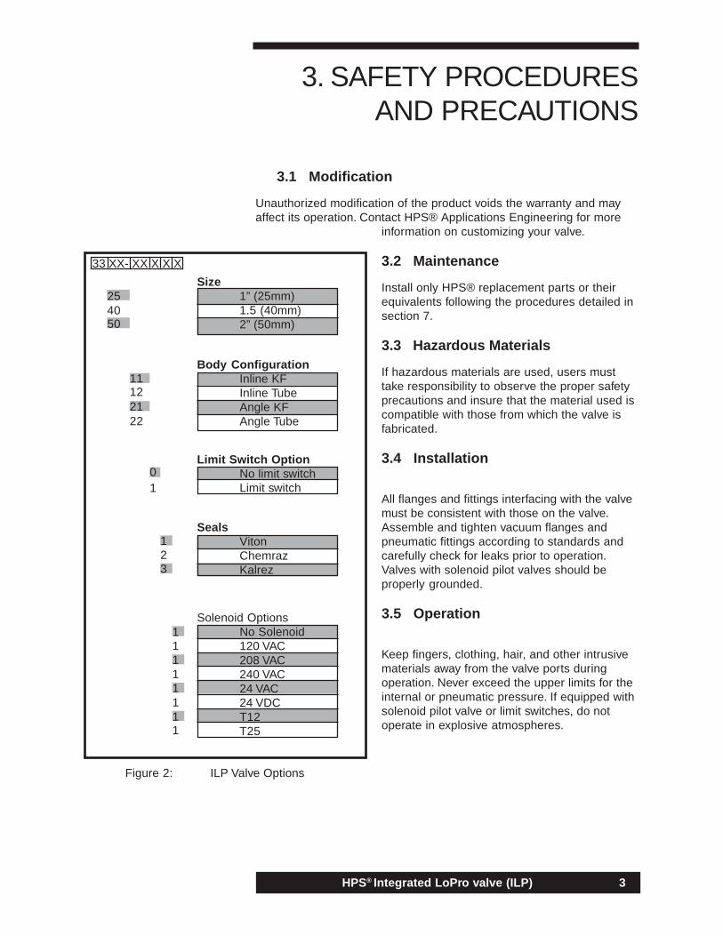
Figure 2: ILP Valve Options
Size1” (25mm)1.5 (40mm)2” (50mm)
Body ConfigurationInline KFInline TubeAngle KFAngle Tube
Limit Switch OptionNo limit switchLimit switch
SealsVitonChemrazKalrez
Solenoid OptionsNo Solenoid120 VAC208 VAC240 VAC24 VAC24 VDCT12T25
33 XX- XX X X X
50
2540
11122122
01
11111111
123
HPS® Integrated LoPro valve (ILP)4
4.1 Pneumatic Cycling
See Figure 8 for valve drawing with part identification, i.e. “bellows (15).”From its normally closed position, the main and bypass valve are openedwith the admission of compressed air to the pneumatic cylinder (23) throughthe 1/8" female NPT ports in the side of the cylinder. A small orifice betweenthis port and the cylinder interior serves as a flow restrictor to determinethe valve opening and closing time. Both stages are normally closed andare held closed with a compression spring (16, 17).
On the main stage, when the pneumatic pressure is applied to the leftport, the cylinder (23) reaches a value sufficient to over come the force ofthe spring, (16) the piston (19) starts to rise, pulling the nosepiece (21)off of the seat. The piston (19) is mechanically attached to the stem thatis welded to the nosepiece. (21) As the nosepiece (21) rises, the bellows(15) is compressed. A small vent groove is located 180 degrees from theactuation ports. This vent allows air to escape from the compressedbellows (18) and to allow for easy Helium leak checking of thebellows(15). The nosepiece (21) is sealed against the seat with anelastomer o-ring (2) that is contained in a trapezoidal groove. The bellows(15) forms a flexible hermetic seal between the nosepiece (21) and thefixed elements of the body. As long as adequate pneumatic pressure andflow is applied, the piston (19) continues to travel upward, furthercompressing the spring, (16) until the valve reaches full open position.Conductance of the main stage is roughly equivalent to 85% of a similarlydimensioned 90° elbow.
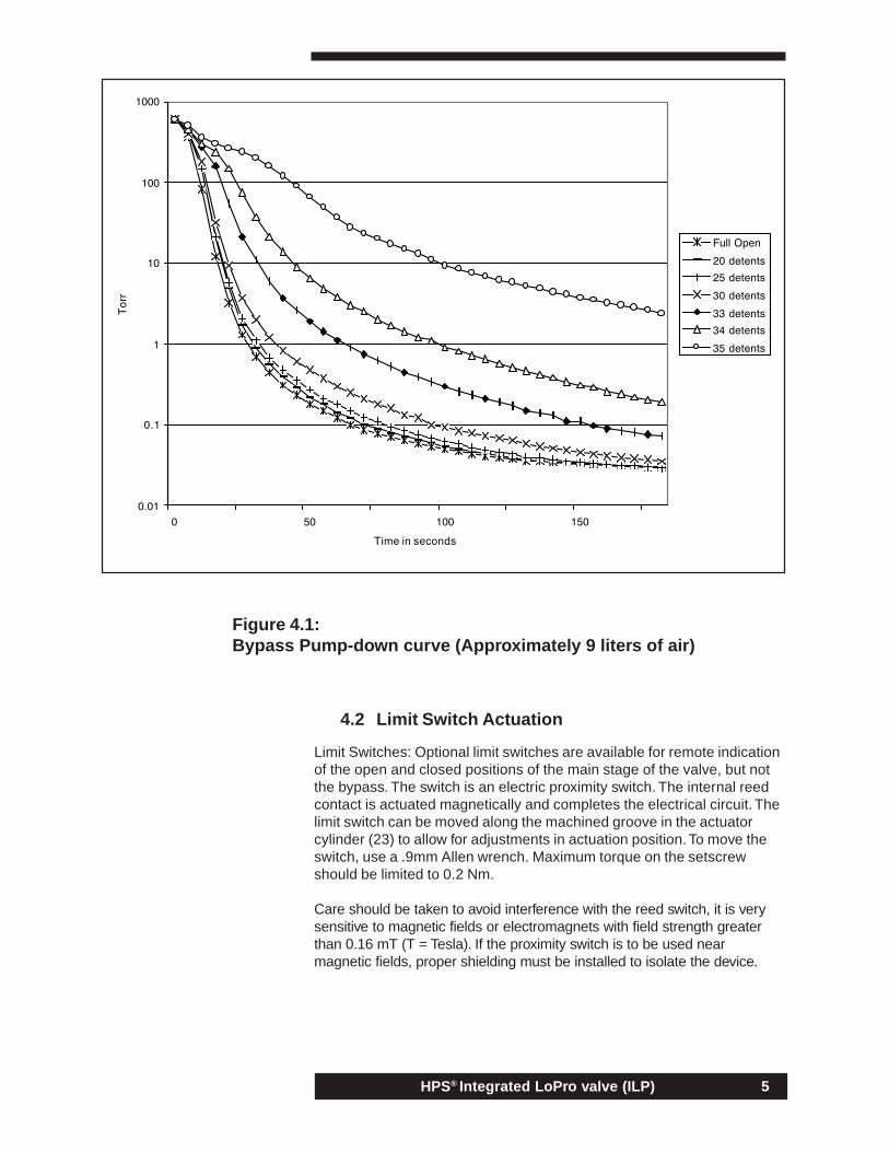
The bypass stage of the valve is also pneumatically actuated throughthe right port. As pressure is applied, the bypass piston (20) is forcedupward, lifting the bypass nosepiece (22) off the seat (18) andcompressing the closing spring (17). This allows for a restricted flowthrough the small orifice on the bypass seat (18). A restricted flow willextend pumpdown times and reduce turbulent flow that may disturbparticles throughout a vacuum system causing particulatecontamination. Once the bypass has allowed for a soft pumpdown to auser specified pressure, the main stage may safely be opened for ahigher conductance and lower base pressure. The bypass stageconductance is adjustable by turning the bypass adjustment screw (13).Turning the bypass screw fully counter-clockwise will allow for maximumconductance. The bypass screw (13) may be turned approximately 3 1/2turns clockwise before it makes contact with the bypass piston (20),which will prevent the bypass from allowing any flow across the ports.The bypass screw (13) has machined detents that lock the screw intoplace during cycling. There are 10 detents per full turn. See figure 4.1for the bypass pump-down curve.
4. OPERATING PRINCIPLES
HPS® Integrated LoPro valve (ILP) 5
4.2 Limit Switch Actuation
Limit Switches: Optional limit switches are available for remote indicationof the open and closed positions of the main stage of the valve, but notthe bypass. The switch is an electric proximity switch. The internal reedcontact is actuated magnetically and completes the electrical circuit. Thelimit switch can be moved along the machined groove in the actuatorcylinder (23) to allow for adjustments in actuation position. To move theswitch, use a .9mm Allen wrench. Maximum torque on the setscrewshould be limited to 0.2 Nm.
Care should be taken to avoid interference with the reed switch, it is verysensitive to magnetic fields or electromagnets with field strength greaterthan 0.16 mT (T = Tesla). If the proximity switch is to be used nearmagnetic fields, proper shielding must be installed to isolate the device.
Figure 4.1:Bypass Pump-down curve (Approximately 9 liters of air)
HPS® Integrated LoPro valve (ILP)6
Observing that the closed position limit switch is actuated does notnecessarily verify that the valve is sealed in a leak tight state, ascontamination or damage to the seal or seat could affect seal integrity. Itdoes confirm, however that the valve and its control obeyed thecommand to move to the closed position.
Technical data:* Function of actuation Normally Open* Operating voltage range 12-27 VDC (24 VDC nominal)* Switching current max. 100mA* Contact rating max. (DC) 1W* Response time on: <0.6 ms* Short-circuit-proof no* Polarity-reversal protection no* Temperature range -20C to +70C* Housing material PPS- reinforced, epoxy resin* Cable material PUR
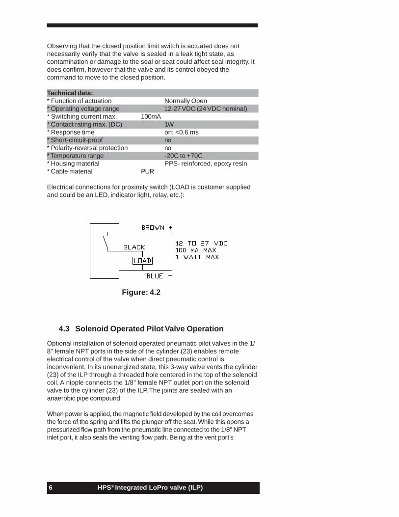
Electrical connections for proximity switch (LOAD is customer suppliedand could be an LED, indicator light, relay, etc.):
4.3 Solenoid Operated Pilot Valve Operation
Optional installation of solenoid operated pneumatic pilot valves in the 1/8" female NPT ports in the side of the cylinder (23) enables remoteelectrical control of the valve when direct pneumatic control isinconvenient. In its unenergized state, this 3-way valve vents the cylinder(23) of the ILP through a threaded hole centered in the top of the solenoidcoil. A nipple connects the 1/8" female NPT outlet port on the solenoidvalve to the cylinder (23) of the ILP. The joints are sealed with ananaerobic pipe compound.
When power is applied, the magnetic field developed by the coil overcomesthe force of the spring and lifts the plunger off the seat. While this opens apressurized flow path from the pneumatic line connected to the 1/8" NPTinlet port, it also seals the venting flow path. Being at the vent port’s
Figure: 4.2
HPS® Integrated LoPro valve (ILP) 7
pressure (usually, but not necessarily atmospheric), the cylinder (23) of theILP is quickly pressurized and the ILP opens.
When power to the solenoid is turned off, the spring forces the plungerback to its original position, simultaneously closing the pressurized portand opening the vent port. Pressurized air in the cylinder (23) of the ILPquickly escapes through grooves on the outside of the plunger and outthe vent port, allowing the ILP to close.
Users may supply their own solenoid operated pilot valve. A solenoidvalve rated for > 1 million cycles continuous duty and a conductance >0.05 cubic inches per minute is recommended. The lengths anddiameters of pneumatic feed lines must also be considered for peakperformance.
4.4 Heaters
The optional heaters available for the ILP valves will keep the minimuminternal operating temperature to 105°C while maintaining a low outsidetemperature. From room temperature, the heaters typically reach theirset temperature in less than 30 minutes.
Heat is distributed with wire heating elements closely and evenlyspaced. Any potential for hot and cold spots is virtually eliminated. Sinceeach heater is uniformly heating a component, there is no need forcostly controllers or thermocouples with messy wires.
The heaters are made of a 1/2 -inch thick silicone foam insulationbonded, using a patented technology, onto a reinforced silicone rubbermat. The heaters’ elastic, conforming shape and convenient snaps makeinstallation and removal fast and easy.
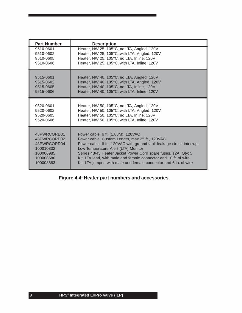
The heaters are easily daisy chained to other HPS® heaters orpowered from a separate power cable (sold separately). Heater optionsinclude 120 or 240 Volt and optional low temperature alert. See Figure4.4 for heater options and part numbers.
HPS® Integrated LoPro valve (ILP)8
Figure 4.4: Heater part numbers and accessories.
Part Number Description9510-0601 Heater, NW 25, 105°C, no LTA, Angled, 120V9510-0602 Heater, NW 25, 105°C, with LTA, Angled, 120V9510-0605 Heater, NW 25, 105°C, no LTA, Inline, 120V9510-0606 Heater, NW 25, 105°C, with LTA, Inline, 120V
9515-0601 Heater, NW 40, 105°C, no LTA, Angled, 120V9515-0602 Heater, NW 40, 105°C, with LTA, Angled, 120V9515-0605 Heater, NW 40, 105°C, no LTA, Inline, 120V9515-0606 Heater, NW 40, 105°C, with LTA, Inline, 120V
9520-0601 Heater, NW 50, 105°C, no LTA, Angled, 120V9520-0602 Heater, NW 50, 105°C, with LTA, Angled, 120V9520-0605 Heater, NW 50, 105°C, no LTA, Inline, 120V9520-0606 Heater, NW 50, 105°C, with LTA, Inline, 120V
43PWRCORD01 Power cable, 6 ft. (1.83M), 120VAC43PWRCORD02 Power cable, Custom Length, max 25 ft., 120VAC43PWRCORD04 Power cable, 6 ft., 120VAC with ground fault leakage circuit interrupt100010832 Low Temperature Alert (LTA) Monitor100006985 Series 43/45 Heater Jacket Power Cord spare fuses, 12A, Qty: 5100008680 Kit, LTA lead, with male and female connector and 10 ft. of wire100008683 Kit, LTA jumper, with male and female connector and 6 in. of wire
HPS® Integrated LoPro valve (ILP) 9
5.1 Environment
5.1.1 Installation Orientation
The Integrated LoPro Series valves function equally well installed in anyorientation.
5.1.2 Applied Forces
As with any vacuum-piping component, improper installation in thevacuum line may result in damage to the component. The strength ofthe Integrated LoPro body is roughly equivalent to an elbow of similarsize. Care must be taken to protect the body of the Integrated LoProfrom excessive stress resulting from torque, thermal expansion, or highamplitude vibration. Where such forces might be encountered, stressbuildup in the vacuum line may be avoided by the proper installation offlexible metal hose(s). The HPS® Applications Engineering departmentis available to help with such problems.
5.1.3 Temperature Extremes
Excessive temperatures, especially in combination with dry air or gas,can cause o-rings and seals to dry out, harden, crack, or even melt,possibly resulting in a vacuum or pneumatic leak.
Lubricating grease used on the stem and piston seal increase theirviscosity at low temperatures, which increases the force required tomove the poppet. Lighter fractions of these lubricants also begin toevaporate at higher temperatures, ultimately resulting in dried lubricant,increased friction on the sliding surfaces, and increasing the forcerequired to move the poppet. While the operating temperatures of theselubricants do not pose immediate problems, regular maintenance, withattention to the condition of the piston and stem lubricants, should beperformed on valves run for extended periods at or near the hightemperature limit.
Heaters are available for the ILP series valves at 105( C. While the ILPvalves may withstand slight intermittent temperature spikes, the valvesare rated for an operating temperature of only 105( C.
5. SPECIFICATIONS
HPS® Integrated LoPro valve (ILP)10
5.2 Operation & Performance
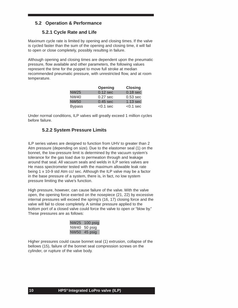
5.2.1 Cycle Rate and Life
Maximum cycle rate is limited by opening and closing times. If the valveis cycled faster than the sum of the opening and closing time, it will failto open or close completely, possibly resulting in failure.
Although opening and closing times are dependent upon the pneumaticpressure, flow available and other parameters, the following valuesrepresent the time for the poppet to move full stroke at medianrecommended pneumatic pressure, with unrestricted flow, and at roomtemperature.
Opening ClosingNW25 0.12 sec 0.18 secNW40 0.27 sec 0.53 secNW50 0.45 sec 1.13 secBypass <0.1 sec <0.1 sec
Under normal conditions, ILP valves will greatly exceed 1 million cyclesbefore failure.
5.2.2 System Pressure Limits
ILP series valves are designed to function from UHV to greater than 2Atm pressure (depending on size). Due to the elastomer seal (1) on thebonnet, the low-pressure limit is determined by the vacuum system’stolerance for the gas load due to permeation through and leakagearound that seal. All vacuum seals and welds in ILP series valves areHe mass spectrometer tested with the maximum allowable leak ratebeing 1 x 10⁻⁹ std Atm cc/ sec. Although the ILP valve may be a factorin the base pressure of a system, there is, in fact, no low systempressure limiting the valve’s function.
High pressure, however, can cause failure of the valve. With the valveopen, the opening force exerted on the nosepiece (21, 22) by excessiveinternal pressures will exceed the spring’s (16, 17) closing force and thevalve will fail to close completely. A similar pressure applied to thebottom port of a closed valve could force the valve to open or “blow by.”These pressures are as follows:
NW25 100 psigNW40 50 psigNW50 45 psig
Higher pressures could cause bonnet seal (1) extrusion, collapse of thebellows (15), failure of the bonnet seal compression screws on thecylinder, or rupture of the valve body.
HPS® Integrated LoPro valve (ILP) 11
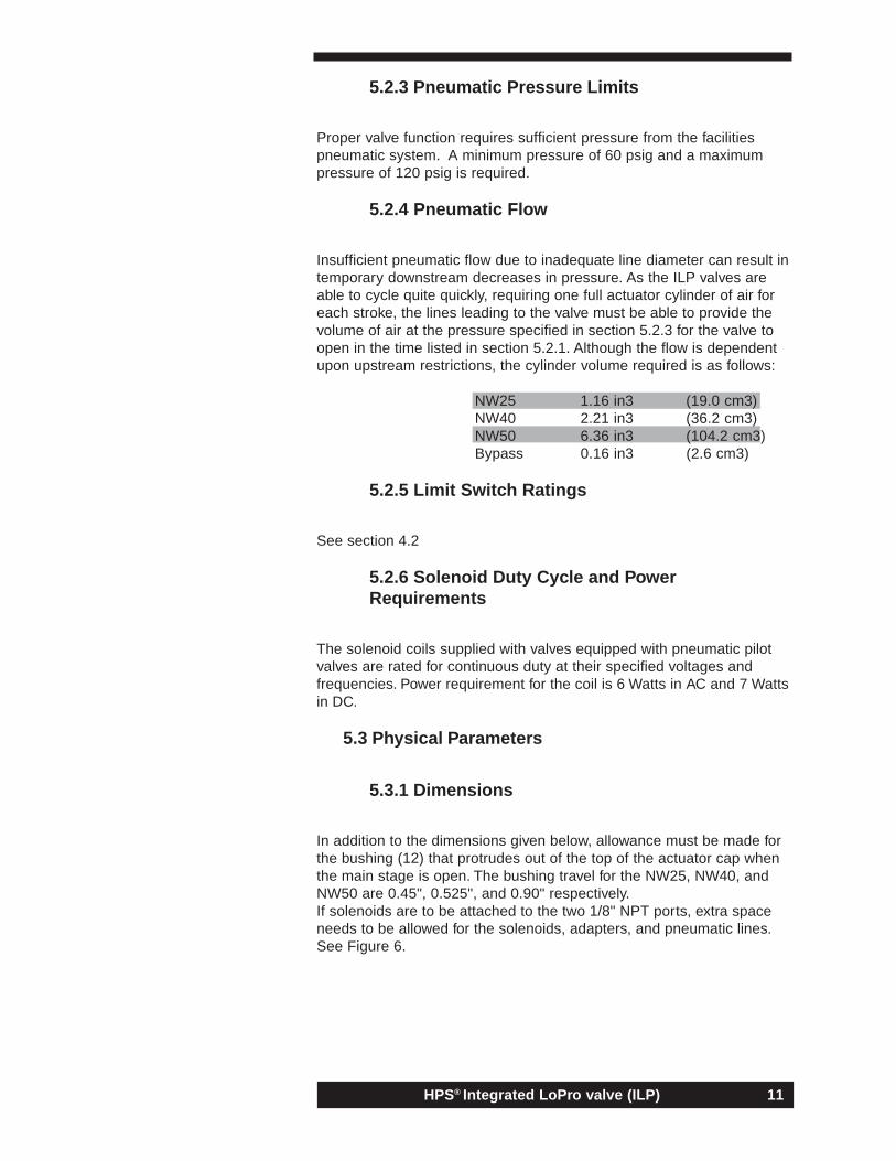
5.2.3 Pneumatic Pressure Limits
Proper valve function requires sufficient pressure from the facilitiespneumatic system. A minimum pressure of 60 psig and a maximumpressure of 120 psig is required.
5.2.4 Pneumatic Flow
Insufficient pneumatic flow due to inadequate line diameter can result intemporary downstream decreases in pressure. As the ILP valves areable to cycle quite quickly, requiring one full actuator cylinder of air foreach stroke, the lines leading to the valve must be able to provide thevolume of air at the pressure specified in section 5.2.3 for the valve toopen in the time listed in section 5.2.1. Although the flow is dependentupon upstream restrictions, the cylinder volume required is as follows:
NW25 1.16 in3 (19.0 cm3)NW40 2.21 in3 (36.2 cm3)NW50 6.36 in3 (104.2 cm3)Bypass 0.16 in3 (2.6 cm3)
5.2.5 Limit Switch Ratings
See section 4.2
5.2.6 Solenoid Duty Cycle and PowerRequirements
The solenoid coils supplied with valves equipped with pneumatic pilotvalves are rated for continuous duty at their specified voltages andfrequencies. Power requirement for the coil is 6 Watts in AC and 7 Wattsin DC.
5.3 Physical Parameters
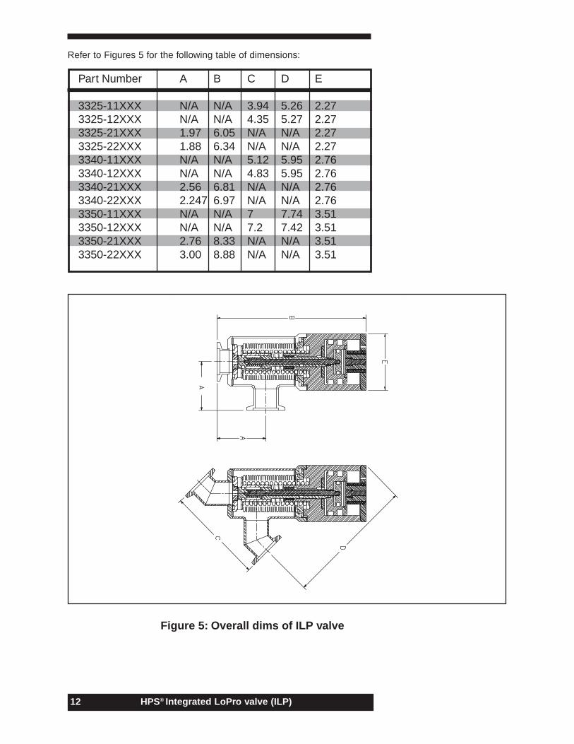
5.3.1 Dimensions
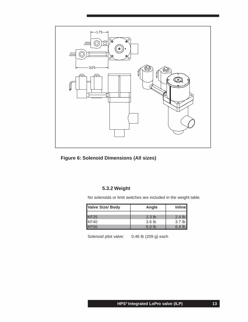
In addition to the dimensions given below, allowance must be made forthe bushing (12) that protrudes out of the top of the actuator cap whenthe main stage is open. The bushing travel for the NW25, NW40, andNW50 are 0.45", 0.525", and 0.90" respectively.If solenoids are to be attached to the two 1/8" NPT ports, extra spaceneeds to be allowed for the solenoids, adapters, and pneumatic lines.See Figure 6.
HPS® Integrated LoPro valve (ILP)12
Part Number A B C D E
3325-11XXX N/A N/A 3.94 5.26 2.273325-12XXX N/A N/A 4.35 5.27 2.273325-21XXX 1.97 6.05 N/A N/A 2.273325-22XXX 1.88 6.34 N/A N/A 2.273340-11XXX N/A N/A 5.12 5.95 2.763340-12XXX N/A N/A 4.83 5.95 2.763340-21XXX 2.56 6.81 N/A N/A 2.763340-22XXX 2.247 6.97 N/A N/A 2.763350-11XXX N/A N/A 7 7.74 3.513350-12XXX N/A N/A 7.2 7.42 3.513350-21XXX 2.76 8.33 N/A N/A 3.513350-22XXX 3.00 8.88 N/A N/A 3.51
Refer to Figures 5 for the following table of dimensions:
Figure 5: Overall dims of ILP valve
HPS® Integrated LoPro valve (ILP) 13
5.3.2 Weight
No solenoids or limit switches are included in the weight table.
Valve Size/ Body Angle Inline
KF25 2.3 lb 2.4 lbKF40 3.6 lb 3.7 lbKF50 6.0 lb 6.4 lb
Solenoid pilot valve: 0.46 lb (209 g) each
Figure 6: Solenoid Dimensions (All sizes)
HPS® Integrated LoPro valve (ILP)14
6.1 Pneumatic Supply
Facility pneumatic supplies often contain contamination including rust,metal particles, oil, and water. The particulate contamination may beremoved by a simple in-line filter in series with the supply for eachvalve, or the supply for an entire system. Available from HPS®, partnumber 100001504, the Master Pneumatic - Detroit, Inc. model FC50-1is a suitable filter for local filtration of typical pneumatic supplies.
The exhaust vents on the solenoid valves originally provided with HPS®valves are internally tapped to accept 10-32 UNF fittings to attach to avent manifold if local external venting is not desired. If desired, a non-restrictive exhaust muffler can be fitted to the valves to help reduce thevent noise.
The piston seal’s sliding surface has been lubricated, making possiblethe use of “dry” pneumatic supplies without harm to the ILP valve.However, the life of the solenoid pilot valve is considerably longer whenthe air supply contains trace quantities of moisture or oil.
6.2 Electrical Connections
Electrical connections must be made whenever the valve is equippedwith limit switches or when using the optional solenoid pilot valves.
Care must be used when soldering leads to the terminals of the limitswitches or solenoid valves. A soldering iron with thermostaticallycontrolled tip should be used. The soldering iron should not be incontact with the switch terminals for longer than 10 seconds.
6.3 Clean Installations
Valves are shipped with plastic covers over the ports. These coversshould be left in place until the valve is installed. All ILP valves arecleaned at the factory for direct installation and high vacuum service.Normal clean assembly techniques should be practiced, as thepresence of airborne particulates on the nosepiece seal, the seat, or onthe sealing surfaces of the port flanges may result in leakage.
6. INSTALLATIONINFORMATION
HPS® Integrated LoPro valve (ILP) 15
6.4 Flange Care
Care should be taken not to damage the flanges. To help protect theflanges, the plastic caps supplied with the valve should remain in placeuntil installation and be replaced when removed from a system. A smallscratch on the flange seal surface of an elastomer sealed flange couldprevent a leak tight seal. Since the flanges are integral with the body, adefective flange could result in a replacement of the body.
When installing the valve, adequate clearance should be allowedbetween adjacent components so there is no sliding of the seal surfacesagainst one another. Flanges that have been assembled for some timemay have a tendency to stick together. Care should be exercised whenprying flanges apart as to avoid damaging their sealing surfaces.
HPS® Integrated LoPro valve (ILP)16
7.1 Removal from System
Prior to removing the entire valve or a valve’s actuator assembly from avacuum system, it is necessary to bring the system up to atmosphericpressure. Purge and vent hazardous gasses appropriately.
Detach the pneumatic supply. To avoid injury, be sure the pneumatic lineis depressurized prior to disconnection from the valve.
If the valve is equipped with the solenoid operated pilot valve, it will benecessary to disconnect these leads. To avoid electric shock orelectrocution, be sure the power to the pilot valve is off prior todisconnection. Refer to section 7.7 for details on solenoid pilot valverepair.
If the valve is equipped with limit switches, the limit switches may beremoved from the valve without disconnecting the leads. The switchesare locked into place with a small setscrew. Before removing the switch,marking the switch’s location with a piece of tape or marker will savetime when reinstalling. To loosen the setscrew, use a 0.9 mm Allenwrench and turn counter-clockwise. Once loose, the switch is free toslide along the groove. The switches may be removed from the top orbottom of the groove. If the actuator is to be removed, the switch mayslide out the bottom. Otherwise, remove the screws that hold the lid(24) in place on the top of the actuator (23), 4 screws on the NW25 andNW40, 6 screws on the NW50. Once the lid (24) is removed the,switches may be slid out the top.
Loosen and remove the clamps or bolts on the port flanges. If possible,pull one of the flanges mating to a port flange directly away from thevalve to allow removal of the valve without scraping sealing surfaces.Replace the protective plastic caps on the port flanges or cover theports with aluminum foil.
Avoid touching the interior surfaces of the valve. Moisture, skin oils, anddirt may contaminate the interior of the valve, affecting its performanceupon reinstallation, and/or, more importantly, films deposited on theinterior surfaces of the valve may be toxic.
7. SERVICE
HPS® Integrated LoPro valve (ILP) 17
7.2 Actuator Assembly
7.2.1 Actuator Assembly Removal andDisassembly
The following procedure does not require removal of the valve bodyfrom the system. However, several aspects of the procedure are moreeasily performed if the entire valve is removed. Section 7.1 should beread for information on solenoid and limit switch removal
The actuator assembly is attached to the bonnet of the valve by 4screws. These screws have been silver plated to ensure easy removalafter thermal cycling.
Sometimes the elastomer nosepiece o-ring seal (2) and the bonnet seal(1) will stick to clean metal sealing surfaces. This is most prevalent withvalves that have been run warm.
After the screws have been removed, pull the actuator assembly out ofthe valve body. The bellows (15) is fabricated of .006" thick 321stainless steel. While withdrawing the actuator assembly (23), careshould be exercised to avoid damaging the bellows. If the bonnet o-ring(1) has adhered to the sealing surface in the body, carefully remove it byhand. If a tool is required for this task, it should be made of a materialsofter than stainless steel to avoid scratching the sealing surface.
CAUTION: The actuator assembly contains a powerful spring (16) undersome compression at all times. Special fixture is required for further,safe disassembly of the actuator. Replacement of malfunctioningactuators with new assemblies is recommended (see parts list insection 7.4 for details).
7.2.2 O-ring Replacement
The bonnet o-ring (1) may be removed easily without special fixturing.With a little stretch, the bonnet o-ring clears the bellow (15) and dropsoff of the actuator assembly (23).
Removal of the nosepiece o-ring (2) on the main stage usually requiresa thin tool to pry it out of its trapezoidal groove. Exercise care to avoiddamaging the sealing surface at the bottom of the groove. Start pryingat the vent hole and carefully move around far enough to allow graspingthe seal with the fingers. Then pull the seal from the remainder of thegroove.
Be sure that no dust or other contamination is in the grooves or on theo-rings. To install the o-rings into the trapezoidal grooves, nest the o-ring on the opening of the groove. With the thumbs at points 180( apart,firmly press the o-ring into the groove. Move 90( and press again. Move45( and press again. Alternately press the o-ring into the groove until itis completely in the groove. Hand installation will likely leave humps on
HPS® Integrated LoPro valve (ILP)18
the installed o-ring. As long as the o-ring has not twisted duringassembly, this will disappear after a small number of cycles, after whichthe valve should function properly.
The bypass has two o-rings that are easily accessible for replacement.A 3/16" Allen wrench is required to remove the bypass seat (18),located in the center of the main stage nosepiece (21). Once the seat(18) is removed, the first o-ring (3) will easily slide off of the seat. Thebypass nosepiece o-ring (4) requires a thin tool to pry it out of thetrapezoidal groove. Care should be taken to avoid damage to thenosepiece sealing surface during removal. Since the seat o-ring (3) iscompressed with a twisting motion, a light coat of vacuum grease isrecommended to prevent damage during reassembly.
The dynamic o-ring (6) in the bypass can be removed and replaced butrequires special tools to access. It is recommended that the entire valvebe removed from the system and returned to an approved MKS servicecenter for repair or replacement.
7.2.3 Actuator Assembly Installation
If applicable, replace the limit switches by sliding them into themachined grooves from the bottom of the actuating cylinder.
Insert the actuator assembly (23) into the valve body. As with removal,take care to avoid damaging the bellows (15). Be sure that the bonneto-ring (1) is in place. The bellows flange is appropriately tapered to aidin retaining the o-ring in the proper position during assembly. Tightenthe four actuator-cap screws until the cap bottoms out on the valvebody. The screws should be lightly tightened in an X pattern, the Xpattern should be repeated 2 to 3 times to ensure all screws are fullyseated. These screws should be sufficiently tight to compress thebonnet o-ring and prevent themselves from loosening.
Reconnect the pneumatic supply and electrical connections (ifapplicable).
It is highly recommended to check the assembly for leaks using a highquality Helium mass spectrometer leak detector. The small rectangularvent located 180 degrees from the pneumatic ports is used for leakdetection. With the interior of the valve evacuated through the side portand attached to the He mass spectrometer, point the tracer gas probetoward this vent. The bellows (15), dynamic o-ring (5), and bonnet seal(1) are accessed for leak detection through this vent. The nosepieceseal and port flange seals may be tested through a variety of methodsand will not be detailed here.
HPS® Integrated LoPro valve (ILP) 19
7.3 Solenoid Pilot Valve Service
In normal use, solenoid pilot valves should last millions of cycles,although this number is reduced by about a factor of ten when a drypneumatic supply is used.
The solenoid valve is held to the actuator cylinder by a 1/8" NPT nippleand the threads are sealed with a jointing compound or TFE thread sealtape. If TFE tape is used, excess tape overlapping the end of the nipplein the assembly can be sheared off, resulting in blockage of pneumaticflow and possible valve failure.
The entire solenoid valve must be replaced in the event of solenoid pilotvalve malfunction. See replacement parts lists, Section 7.4 for solenoidpart numbers.
HPS® Integrated LoPro valve (ILP)20
7.4 Replacement Parts List
NW25 ILP valvesActuator Assembly w/ Viton(R) 100011461Actuator Assembly w/ Chemraz(R) 100011464Actuator Assembly w/ Kalrez(R) 100011467Viton(R) seal kit 100011470Chemraz(R) seal kit 100011473Kalrez(R) seal kit 100011476Limit switch kit (qty: 2) 100011479
NW40 ILP valvesActuator Assembly w/ Viton(R) 100011462Actuator Assembly w/ Chemraz(R) 100011465Actuator Assembly w/ Kalrez(R) 100011468Viton(R) seal kit 100011471Chemraz(R) seal kit 100011474Kalrez(R) seal kit 100011477Limit switch kit (qty: 2) 100011479
NW50 ILP valvesActuator Assembly w/ Viton(R) 100011463Actuator Assembly w/ Chemraz(R) 100011466Actuator Assembly w/ Kalrez(R) 100011469Viton(R) seal kit 100011472Chemraz(R) seal kit 100011475Kalrez(R) seal kit 100011478Limit switch kit (qty: 2) 100011479
Solenoid pilot valves24 VDC (7.0 Watts) 10000816324 VAC 50/60 Hz (6.0 Watts) 100008164120VAC 50/60 Hz (7.5 Watts) 100008165208VAC 50/60 Hz (7.5 Watts) 100008166220VAC 50/60 Hz (7.5 Watts) 10000816712VDC (7.0 Watts) 100008539
HPS® Integrated LoPro valve (ILP) 21
The following sections outline diagnoses of possible problemsencountered when using HPS® Integrated LoPro Series valves anddetail possible causes and their remedies.
8. TROUBLE SHOOTING
Figure 8: Part Identification
HPS® Integrated LoPro valve (ILP)22
8.1 PROBLEMS AND DIAGNOSES
8.1.1 Won’t close completely
The most common reason for either the main or bypass stage of the ILPnot to close completely is due to failure of the compression springs (16,17). Further evidence of main-stage spring failure would include; highmagnitude leak across nosepiece seal (2), bushing (12) not flush withtop of valve and/or the limit switch not indicating full close.If you suspect the bypass stage is not closing completely due to a highmagnitude leak, you can manually shut the bypass by fully closing(clockwise) the adjustment screw (13) on the top of the valve. If thisseals the valve, the bypass spring (17) has likely failed. See section8.2.1 for recommended service.
8.1.2 Won’t open completely
Failure to open completely can be detected directly by the absence of asignal from the open limit switch (if so equipped). It can also beobserved by the position of the main-stage bushing (12). When thebypass stage opens there should be a sharp metallic sound as thebypass piston (20) hits the bypass adjustment screw (13). Lastly, asignificant decrease in the valve’s conductance may be an indication.
First, see section 8.2.16 on inadequate air pressure. If pneumatic pressureis within recommended limits and compressed air is leaking and possiblyheard through the hole in the piston lid (24) but is not coming out of theside vent located 180 degrees from the pneumatic ports, then see section8.2.9 on piston seal leakage. If the air is spraying through the side ventwhile the valve is static, see section 8.2.10 on stem seal leakage. Lastly, ifthere are no other symptoms other than incomplete opening, see section8.2.14 on loose pistons (19, 20).
8.1.3 Opens slowly or in jumps
An abnormally long delay between signals from the two limit switches isdirect evidence of slow opening. It can also be observed from thebushing (12) location and comparing the actuation time to that in thespecifications. The vibration caused by slip stick jumps can often be feltmanually and sometimes heard.
First, see section 8.2.16 on inadequate air pressure. If pneumaticpressure is within recommended limits, refer to section 8.2.17 coveringinadequate airflow. Lastly, see section 8.2.15 on inadequate orexhausted lubrication.
8.1.4 Won’t open at all
Continuation of the signal from the closed limit switch (if so equipped)and zero conductance through the valve are both good indications thatthe valve has not opened. Visual observation of the piston’s failure to
HPS® Integrated LoPro valve (ILP) 23
move can be made from the bushing (12) position on the main stage.First, see section 8.2.16 on inadequate air pressure. If pneumaticpressure is within recommended limits, refer to section 8.2.2 on stemweld failure. Lastly, if air is leaking from the side vent when the valve istrying to open, see section 8.2.14 on loose pistons (19, 20).
8.1.5 Squeaks when opening and/or closing
ILP valves normally make a barely audible squeak when they open andclose. This is caused by the spring (16) making contact with the bushing(NW40 and 50 only) that prevents the spring from buckling anddamaging critical components.
A loud grinding or squeaking may be indicative of a problem. If there seemsto be loose components rattling about inside the valve, see section 8.2.1 onspring failure. Also check section 8.2.15 on inadequate lubrication.
8.1.6 Leaks across closed nosepiece seal
Detection of leakage across the nosepiece seal (2) when the valve isclosed can be symptomatic of several problems. See section 8.1.1 if thevalve is also not closing completely.
Refer to section 8.2.12 on nosepiece seal (2) omission. If the o-ring ispresent, particles, contamination, and corrosion may be the problem, seesection 8.2.5. If the valve continues to leak after the seat and sealing areahave been cleaned, see section 8.2.8 on bonnet seal failure.
8.1.7 Leaks from atmosphere when closed
If leakage is detected from atmosphere when the valve is closed, seesection 8.2.13 on improper assembly. If the assembly is correct, refer tosection 8.2.8 on bonnet seal failure and 8.2.20 on dynamic seal failure.Last, see section 8.2.3 on body damage.
8.1.8 Leaks from atmosphere when open
If leakage is detected from atmosphere when the valve is open, seesection 8.2.6 on bellows failure and 8.2.20 on dynamic seal failure.
8.1.9 Leaks from atmosphere at all times
If leakage is detected from atmosphere at all times, see section 8.2.6 onbellows failure. If the bellows (15) has not failed, refer to section 8.2.8 onbonnet seal failure. Also see sections 8.2.11 on bonnet seal omission,8.2.13 on improper assembly, 8.2.3 on body damage, and 8.2.4 on portflange damage.
HPS® Integrated LoPro valve (ILP)24
8.1.10 Air leaks from around piston when open
If compressed air can be heard and possibly felt escaping from the venthole in the actuator lid (24), but is not emanating from the vent in the sideof the actuator (23), 180 degrees from the pneumatic ports, see section8.2.9 on piston seal failure.
8.1.11 Air leaks from vent hole while operating
The vent located on the side of the actuator (23), vents the interior of thebellows as its volume changes during the stroke. This venting is normal andnecessary while the valve is dynamic (opening or closing), and can be feltas a puff of air through the hole in the piston cover while opening.
8.1.12 Air leaks from vent hole when open
If compressed air can be felt escaping from the side vent, see section8.2.10 on stem seal (7,8,9) failure.
8.1.13 Limit switches don’t send signal
Be sure that the valve is opening and/or closing completely, seesections 8.1.1 and 8.1.2. If the valve has traveled its full stroke, seesection 8.2.18 about limit switch failure.
8.1.14 Solenoid valve buzzes or doesn’t work
If air is not passing through the solenoid pilot valve or is buzzing duringactivation, see section 8.2.19 on solenoid valve failure.
8.1.15 Air leaking from non-actuated port orsolenoid
When air leaks from one pneumatic port or solenoid vent while theother is actuated, stem seal failure is likely. See section 8.2.10 on Stemseal failure.
8.2 CAUSES AND REMEDIES
8.2.1 Spring failure
The normal Integrated LoPro valve springs have lifetimes greater than 1x 10⁶ cycles. In the rare event of a failure, due to the special fixturingrequired for complete disassembly of the actuator assembly the valvemust be returned for service. See section 9 for Return to Factory forRepair or Service.
8.2.2 Stem weld failure
If the piston is actuating but the valve remains closed, stem weld failure(or a loose piston) could be the problem. See section 9 for Return toFactory for Repair or Service.
HPS® Integrated LoPro valve (ILP) 25
8.2.3 Body damage
All Integrated LoPro valves are thoroughly tested after assembly. Bodydamage serious enough to result in detectable leakage could be causeby mishandling or abuse in shipping or in the installation. A damagedbody is not easily repaired, usually costing more than a replacement.Often, with serious body damage, the actuator assembly has also beendamaged, making replacement of the entire valve the best solution.
8.2.4 Port flange damage
Flanges are easily damaged after the protectors have been removed.Avoid contact between the flanges and any surface. Small sealingsurface defects can sometimes be corrected with application of a goodquality vacuum grease, such as Apiezon*, to the seal. Larger defectsmight be repaired by rubbing out the scratch or dent with a lightabrasive, such as Scotch Bright*. Working of the abrasive should alwaysbe parallel to the direction of the seal. For example, a scratch on asurface sealed by a circular o-ring- should, likewise, be worked with theabrasive in a circular fashion. Heavier damage would requirereplacement of the body.
8.2.5 Particulates, condensation, and corrosion
In normal use, airborne particulates, process condensation, and/orcorrosion, may affect seal integrity. Particulates might be moved bysimple turbulent gas flow. However, condensed or sublimates filmsnearly always require further cleaning. Additionally, corroded sealingsurfaces may be irreparable. In this case, replacing the componentwould be the only remedy.
8.2.6 Bellows failure
Although the mean time between failures for the Integrated LoProbellows is greater than (106) cycles, nearly all valve failures are the resultof bellows failures. Stress cracks in the convolution crowns are firstdetected when the valve is open and the bellows are in compression. Atthis time, the outside of the bellows material is in tension, opening minutecracks wider than when the bellows is relaxed or in extension. Eventually,the crack(s) will propagate around the entire convolution and the bellowswill separate. Long before, the atmospheric leak will be detectedconstantly. The only remedy is to replace the actuator assembly.
8.2.7 Nosepiece seal failure
Elastomer seals that have remained in a compressed condition for longperiods of time may not return to their circular cross sectional shapewhen released. Such seals may stick to the mating sealing surface asthey are pulled apart, leaving bits of the seal behind. Old elastomerstend to lose some of their elasticity and may crack. Various processgasses and/or high temperatures accelerate all of these effects.Reference section 7.2.2 on o-ring replacement.
HPS® Integrated LoPro valve (ILP)26
8.2.8 Bonnet seal Failure
Elastomer seals that have remained in a compressed condition for longperiods of time may not return to their circular cross sectional shapewhen released. Such seals may stick to the mating sealing surface asthey are pulled apart, leaving bits of the seal behind. Old elastomerstend to lose some of their elasticity and may crack. Various processgasses and/or high temperatures accelerate all of these effects.Reference section 7.2.2 on 0-ring replacement.
8.2.9 Piston seal failure
The seals (10, 14) used on the ILP’s pistons are normally good for morethan 106 cycles. However, an occasional defect in the material, damagecaused during the seal’s installation, or inadequate lubrication couldcause seal failure, resulting in a pneumatic leak. Due to the specialfixturing required to fully disassemble the actuator assembly, factoryrepair or replacement is recommended.
8.2.10 Stem seal failure
The seals used on the ILP’s stem are normally rated for much morethan 106 cycles. However, an occasional defect in the material, damagecaused during the seal’s installation, or inadequate lubrication couldcause seal failure, resulting in a pneumatic leak. Due to the specialfixturing required to fully disassemble the actuator assembly, factoryrepair or replacement is recommended.
8.2.11 Bonnet seal omission
After service, during reassembly, omission of the bonnet seal will causethe valve to leak from atmosphere at all times. Remove the actuatorassembly and install the seal.
8.2.12 Nosepiece seal omission
After service, during reassembly, omission of the seals (2, 3 or 4) willcause the valve to leak from one port to the other when the valve isclosed. Remove the actuator assembly and install the seal.
8.2.13 Improper assembly
After service, the actuator must be inserted to its stop, referencesection7.2.3 on actuator assembly installation. Failure to do so could resultin the valve not closing completely, or leaking in its closed position.
8.2.14 Loose piston
In the unlikely case that either piston, bypass (20) or main (19) shouldunscrew itself, the valve would no longer be able to open. Due to thespecial fixturing required to fully disassemble the actuator assembly,factory repair or replacement is recommended.
HPS® Integrated LoPro valve (ILP) 27
8.2.15 Inadequate lubrication
Normally the ILP’s dynamic components require very little lubrication.However, dry environments, high temperatures, and corrosiveatmospheres may exhaust most of the lubricating properties of thegreases used. This could increase the friction on the piston and stemand could result to damaged components and failure. Remove thepiston lid (24) and apply a film of a high quality lubricant for elastomer/metal interfaces to the inside of the cylinder. Cycle the valve severaltimes and reapply the grease.
8.2.16 Inadequate air pressure
The specifications define minimum operating pressures for ILP valves. Ifthe pneumatic supply pressure is too low, it must be increased.
8.2.17 Inadequate air flow
More difficult to detect than inadequate pressure, low flow may cause slowactuation of the valve. If the pneumatic line is equipped with a gauge, watchthe pressure as the valve is actuated. If it decreases significantly with eachslow actuation then pneumatic flow is inadequate. Check for kinks or otherblockages in the line. If the low flow is due to demand greater than capacity,installation of additional capacity must be considered.
8.2.18 Limit switch failure
First, refer to section 4.2 to insure the switch is wired properly. Second,if the switch appears to be wired properly, try adjusting the switchlocation by loosening the setscrew and sliding it along the groove untilyou get a visual indication from the integrated LED. Next, if the switch iswired properly, remove it from the groove and check its function with apermanent magnet. If the switch is operating properly with thepermanent magnet, the piston magnet (11) may have been omitted ordemagnetized by a strong magnetic field or excessive heat. If theswitch does not function, it must be replaced, see section 7.4 for thereplacement parts list.
8.2.19 Solenoid valve failure
During long or quickly repeated duty cycles, the solenoid valve’s coil willnormally exceed 70o C. Voltages lower than specified can increase thattemperature and accelerate the failure of the coil. Incorrect voltages cancause immediate failure and subsequent replacement of the solenoidvalve’s coil.
Dirt or other contamination from the pneumatic supply can inhibit themovement of the plunger and cause the valve to leak. Sometimes thisproblem manifests itself in an oscillation of the plunger, resulting in areadily audible buzz. The best remedy is to replace the entire solenoidvalve. Installation of a filter in the pneumatic line upstream from the valvecan prolong the life of the valve.
HPS® Integrated LoPro valve (ILP)28
8.2.20 Dynamic bypass seal failure
Due to the special tools and fixturing required to replace this seal, returnof the valve to the factory for service is recommended.
HPS® Integrated LoPro valve (ILP) 29
Before shipping an Integrated LoPro valve to the factory, pleaseobserve the following procedure:
9.2 Call the factory
The HPS® Customer Service Department or any MKS Service Center willprepare a Returned Materials Report (RMR). Consequently, when the itemis received, it will be dispositioned in a timely manner.
The customer service person will need information on the following:* What is the problem?* What are the symptoms, and how were they observed?* What is the application?* Is it an urgent repair?* What is the valve’s serial number?* What is the user’s name and where can he/she be reached?* Was the valve used with any dangerous, toxic, or radioactivematerials?HPS® is not equipped to handle such items. Items having ANYunidentified coatings or films will be treated as hazardous waste andappropriately disposed at the sender’s expense. Additionally, theshipment of hazardous materials through the mail or on any privatecarrier not specifically licensed for the handling of such materials is afederal offense.
With this information, the customer service person will issue an RMRnumber specific to this return.
9.3 Prepare for shipment
Be sure the valve is clean and free of any hazardous materials. Cap theports to prevent entry of foreign material and to protect the sealingsurfaces. Place the valve in a sealed plastic bag, and pack securely in asturdy shipping container. Poor packing can result in damage to thevalve. Insert a packing slip or letter referencing the RMR number issuedby the customer service person.
9.4 Payment
Warranty repairs or replacement are performed at no cost. If the itemreturned is no longer under warranty, a purchase order for the cost ofthe repair will be required. Of course, an estimate of the repair cost willbe provided.
9 RETURN TO FACTORY FORREPAIR OR SERVICES
HPS® Integrated LoPro valve (ILP)30
10.1 Coverage
HPS® Products of MKS Instruments, Inc. (“HPS®”) warrants IntegratedLoPro Series valves to be free from defects in materials andworkmanship for a period of (ONE YEAR) from the date of shipment byHPS® or it’s authorized representative to the original purchaser(“Purchaser”). Any product or parts of the product repaired or replacedby HPS® under this warranty are warranted only for the remainingunexpired portion of the (one year) original warranty period applicableto the product that has been repaired or replaced. After expiration of theapplicable warranty period, the Purchaser shall be charged currentprices for parts and labor, plus any transportation for any repairs orreplacement.
The obligation of HPS® under this warranty shall be, at its option, torepair, replace or adjust the product so that it meets applicable productspecifications published by HPS®, or to refund the purchase price.
10.2 WARRANTY PERFORMANCE
To obtain warranty satisfaction, contact your local MKS Instruments, Inc.district sales office or:
HPS® Division of MKS Instruments, Inc.5330 Sterling DriveBoulder, CO 80301Voice 303-449-9861 Fax 303-442-6880
10.3 WHAT IS NOT COVERED
The above warranties do not apply to the following:
> Damages or malfunction due to failure to provide reasonable andnecessary maintenance in accordance with HPS® operating instructions.> Damages or malfunctions due to chemical or electrolyte influences, oruse of the product in working environments outside the specifications.> Seals, bellows, and all expendable items which by their nature orlimited lifetime may not function for one year. (If such items fail to givereasonable service for a reasonable period of time within the warrantyperiod of the product, they will, at the option of HPS®, be repaired orreplaced.)> Defects, damages, or malfunctions caused by modifications and/orrepairs effected by the Purchaser or unauthorized third parties.
10 WARRANTY
HPS® Integrated LoPro valve (ILP) 31
10.4 THEIR RIGHTS AND REMEDIES
HPS® SHALL NOT BE LIABLE FOR CONSEQUENTIAL DAMGES, FORANTICIPATED OR LOST PROFITS, INCIDENTAL DAMAGES, OR LOSSOF TME OR OTHER LOSSES INCURRED BY THE PURCHASER OR BYANY THIRD PARTY IN CONNECTION WITH THE PRODUCT COVEREDBY THIS WARRANTY, OR OTHERWISE. Some states do not allow theexclusion or limitation of incidental or consequential damages, so theabove limitation or exclusion may not apply.
Any implied warranty on these products shall be limited to (one year)from date of shipment to Purchaser. Some states do not allowlimitations on how long an implied warranty lasts, so the above limitationmay not apply.
Unless otherwise explicitly agreed in writing, it is understood that theseare the only written warranties given by HPS®. Any statements made byany persons including representatives of HPS® which are inconsistent orin conflict with the terms of the warranty shall not be binding on HPS®
unless reduced to writing and approved by an authorized officer of HPS®.
This warranty gives you specific legal rights and you may also haveother rights which may vary from state to state.1
1

HPS® Integrated LoPro valve (ILP)32