Embed Size (px)
Citation preview
HPUSB, USB, HPPCI and MSP430Emulators Users Guide
Revision 2.0, January 2005
Part Number82-000760-01
Analog Devices, Inc.One Technology WayNorwood, Mass. 02062-9106
a
Copyright Information© 2005 Analog Devices, Inc., ALL RIGHTS RESERVED. This docu-ment may not be reproduced in any form without prior, express written consent from Analog Devices, Inc.
Printed in the USA.
NoticeAnalog Devices, Inc. reserves the right to make changes to or to discon-tinue any product or service identified in this publication without notice.
Analog Devices assumes no liability for Analog Devices applications assis-tance, customer product design, customer software performance, or infringement of patents or services described herein. In addition, Analog Devices shall not be held liable for special, collateral, incidental or conse-quential damages in connection with or arising out of the furnishing, performance, or use of this product.
Analog Devices products are not intended for use in life-support applica-tions, devices, or systems. Use of an Analog Devices product in such applications without the written consent of the appropriate Analog Devices officer is prohibited.
Users are restricted from copying, modifying, distributing, reverse engi-neering and reverse assembling or reverse compiling the Analog Devices emulator operational software (one copy may be made for back-up pur-poses only).
Limited WarrantyThe USB and PCI based emulators hardware is warranted against defects in materials and workmanship for a period of one year from the date of purchase from Analog Devices or from an authorized dealer.
Trademark and Service Mark NoticeThe Analog Devices logo, VisualDSP++, Blackfin, TigerSHARC, SHARC, the CROSSCORE logo, EZ-KIT Lite, and EZ-ICE are regis-tered trademarks are registered trademarks of Analog Devices, Inc.
All other brand and product names are trademarks or service marks of their respective owners.
Regulatory Compliance The USB and PCI based emulators are designed to be used solely in a lab-oratory environment. The emulator is not intended to be used in any end products or as a portion of an end product. The emulators may cause interference to other electronic devices operating at close proximity. The emulators should not be used in or near any medical equipment or RF devices.
The USB and PCI based emulators have been certified to comply with the essential requirements of the European EMC directive 89/336/EEC (inclusive 93/68/EEC) and, therefore, carries the “CE” mark.

The USB and PCI based emulators have been appended to Analog Devices Development Tools Technical Construction File referenced “DSPTOOLS1” dated December 21, 1997 and was awarded CE Certifi-cation by an appointed European Competent Body and is on file.
The EZ-KIT Lite evaluation system contains ESD (electrostatic discharge) sensitive devices. Electro-static charges readily accumulate on the human body and equipment and can discharge without detection. Permanent damage may occur on devices subjected to high-energy discharges. Proper ESD precautions are recommended to avoid performance degradation or loss of functionality. Store unused EZ-KIT Lite boards in the protective shipping package.
CONTENTS
PREFACE
Purpose of This Manual .................................................................. ix
Intended Audience .......................................................................... ix
Manual Contents ............................................................................. x
Technical or Customer Support ........................................................ x
GETTING STARTED
Contents of Emulator Package ....................................................... 1-2
PC Configuration ......................................................................... 1-2
Installation Tasks .......................................................................... 1-3
Installing USB Based Emulators ............................................... 1-3
Installing PCI Based Emulators ................................................ 1-3
Verifying Driver Installation .................................................... 1-4
Attaching Cable to Emulation Target ............................................. 1-5
JTAG Frequency Selection ............................................................. 1-6
HPPCI JTAG Voltage Detection ................................................... 1-8
HPUSB/USB Legacy Mode ..................................................... 1-8
HPPCI Legacy/Auto Detection Mode .................................... 1-10
Legacy Mode (Factory Default Setting) .................................. 1-11
HPUSB, USB, HPPCI and MSP430 Emulators User’s Guide v
CONTENTS
Auto Detection Mode ........................................................... 1-12
HARDWARE DESCRIPTION
LEDs ........................................................................................... 2-1
HPUSB-ICE/USB-ICE LEDs ................................................. 2-1
HPPCI-ICE LEDs .................................................................. 2-2
Pod LEDs ............................................................................... 2-2
Board LEDs ............................................................................ 2-3
MSP430-ICE LED ................................................................. 2-4
Designing Custom Processor Boards .............................................. 2-4
Mechanical Specifications ............................................................. 2-5
HPPCI-ICE ............................................................................ 2-5
SUPPORT
Technical Support ......................................................................... 3-1
Quality Assurance ......................................................................... 3-1
REFERENCES
INDEX
vi HPUSB, USB, HPPCI and MSP430 Emulators User’s Guide
PREFACE
Thank you for purchasing an Analog Devices USB or PCI based JTAG
emulator. The USB-based emulator family consists of the High Perfor-mance USB JTAG emulator, the USB JTAG emulator, and the MS430 emulator. The USB and PCI based emulators are used in conjunction with the VisualDSP++® development environment to create, test, and debug advanced processor application software on all of Analog Devices fixed point and floating point JTAG based DSPs.The HPUSB-ICE system provides state-of-the-art support for JTAG-com-pliant Analog Devices processors. Key features of the HPUSB-ICE include:
• Plug-n-Play, USB 2.0 compliant
• High speed USB device
• Windows® 2000 or Windows XP operation
• Multiple processor IO voltage support
1.8V, 2.5V, and 3.3V compliance
5V tolerant in all ranges
• Multiprocessor support
• JTAG clock operation up to 50 MHz
HPUSB, USB, HPPCI and MSP430 Emulators User’s Guide vii
The HPPCI-ICE system provides state-of-the-art support for JTAG-com-pliant Analog Devices processors. Key features of the HPPCI-ICE include:
• Plug-n-Play, PCI 2.2 compliant
• Windows 2000 or Windows XP operation
• Multiple processor IO voltage support
1.8V, 2.5V, and 3.3V compliance
5V tolerant in all ranges
• Multiprocessor support
• JTAG clock operation up to 50 MHz
The JTAG clock frequency is dependent on the delay characteris-tics of the JTAG interface and processor on the target board.
The USB-ICE system provides state-of-the-art support for selected proces-sors within the Analog Devices MCP430 processor family. Key features of the USB-ICE include:
• Plug-n-Play, USB 2.0 compliant
• High-speed USB device
• Windows 2000 or Windows XP operation
• Multiple processor I/O voltage support
1.8V, 2.5V, and 3.3V compliance
5V tolerant in all ranges
• Multiprocessor support
• JTAG clock operation of 10 MHz
viii HPUSB, USB, HPPCI and MSP430 Emulators User’s Guide
Preface
The MSP430-ICE system provides state-of-the-art support for selected processors within the Analog Devices MSP430 processor family. Key fea-tures of the MSP430-ICE include:
• Plug-n-Play, USB 2.0 compliant
• Full-speed USB device
• Windows 2000 or Windows XP operation
• Processor I/O voltage support
3.3V compliance
Purpose of This Manual The HPUSB, USB, HPPCI and MSP430 Emulators User’s Guide provides directions for installing the High Performance USB-ICE, USB ICE, High Performance HPPCI-ICE, and MSP430-ICE hardware and software on your PC. The manual also describes how to configure and use the compo-nents of the USB and PCI based emulators.
Intended AudienceThis manual is intended to help the customer understand the features and operation of the HPUSB-ICE, HPPCI-ICE, USB-ICE, and MSP430-ICE so they can begin using VisualDSP++.
HPUSB, USB, HPPCI and MSP430 Emulators User’s Guide ix
Manual Contents
Manual ContentsThe manual consists of:
• Chapter 1, “Getting Started” on page 1-1Provides software and hardware installation procedures, PC system requirements, and basic board information.
• Chapter 2, “Hardware Description” on page 2-1Provides information on hardware aspects of the USB-based emulators.
• Chapter 3, “Support” on page 3-1Provides technical support contact information.
• Chapter 4, “References” on page 4-1Provides information on different resources available in developing an ADI processor application.
Technical or Customer SupportYou can reach DSP Tools Support in the following ways.
• Visit the Embedded Processing and DSP products Web site athttp://www.analog.com/processors/technicalSupport
• E-mail tools questions [email protected]
• E-mail processor questions [email protected]
• Phone questions to 1-800-ANALOGD
x HPUSB, USB, HPPCI and MSP430 Emulators User’s Guide
Preface
• Contact your Analog Devices, Inc. local sales office or authorized distributor
• Send questions by mail to:
Analog Devices, Inc.
One Technology Way
P.O. Box 9106
Norwood, MA 02062-9106
USA
HPUSB, USB, HPPCI and MSP430 Emulators User’s Guide xi
Technical or Customer Support
xii HPUSB, USB, HPPCI and MSP430 Emulators User’s Guide
1 GETTING STARTED
This chapter provides the information needed to begin using the USB and
PCI based emulators.This chapter includes the following sections.
• “Contents of Emulator Package” on page 1-2Provides a list of the components that are shipped with the USB and PCI based emulators.
• “PC Configuration” on page 1-2Describes the minimal PC requirements.
• “Installation Tasks” on page 1-3Describes the step-by-step procedure for setting up the emulator hardware.
• “Attaching Cable to Emulation Target” on page 1-5 Describes how to connect a USB, PCI, and MSP43 emulators to your target board.
• “JTAG Frequency Selection” on page 1-6Describes how to change the JTAG frequency.
• “HPPCI JTAG Voltage Detection” on page 1-8Describes the JTAG voltage detection features of the emulators.
HPUSB, USB, HPPCI and MSP430 Emulators User’s Guide 1-1
Contents of Emulator Package
Contents of Emulator PackageUSB Based Emulator:
Your USB based emulator package contains the following items.
• HPUSB-ICE, USB-ICE, or MSP430 assembly
• 5 volt power supply
• 3 meter USB type-A to mini-B cable
• Registration card – please fill out and return
HPPCI-PCI Emulator:
Your High Performance PCI emulator package contains the following items.
• HPPCI-ICE or JTAG daughter card
• HPPCI-ICE pod assembly
• Registration card – please fill out and return
PC ConfigurationFor correct operation of the USB or PCI based emulator, your computer must have the minimal configuration:
1. Windows 2000 or Windows XP
2. VisualDSP++ 3.5 or later
3. USB full or high speed port (for USB based emulators)
4. One available PCI slot (for PCI based emulators)
1-2 HPUSB, USB, HPPCI and MSP430 Emulators User’s Guide
Getting Started
Installation TasksThe following tasks are provided for the safe and effective installation of the USB and PCI based emulator. Follow these instructions in the pre-sented order to ensure correct operation of your software and hardware.
Installing USB Based Emulators1. Connect power to the USB assembly.
2. Connect the USB cable to the USB assembly and a USB port of your computer.
3. Install VisualDSP++ 3.5 or later. VisualDSP++ includes the USB driver needed for your USB emulation hardware. VisualDSP++ can be installed on Windows 2000 or Windows XP. Refer to the Instal-lation Quick Reference Card for details.
4. Verify driver installation.
Installing PCI Based Emulators1. Install the HPPCI -ICE hardware. For specific instructions on
installing a PCI card into your computer, consult the documenta-tion provided by the computer manufacturer.
2. Install VisualDSP++ 3.5 or later. VisualDSP++ includes the HPPCI driver needed for your PCI emulation hardware. Visu-alDSP++ can be installed on Windows 2000 or Windows XP. Refer to the Installation Quick Reference Card for details.
3. Verify driver installation
The driver must be installed before you start the HPPCI-ICE for the first time.
HPUSB, USB, HPPCI and MSP430 Emulators User’s Guide 1-3
Installation Tasks
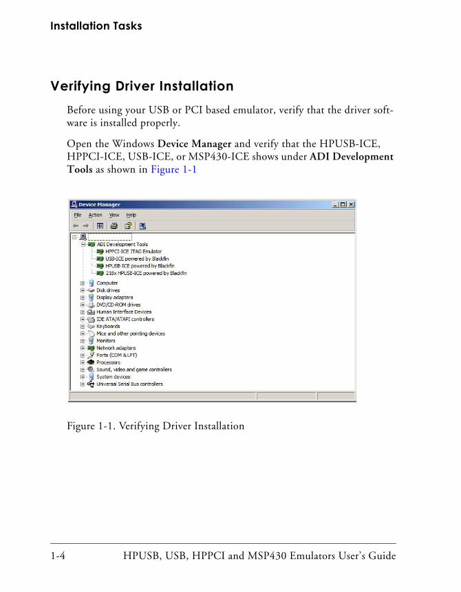
Verifying Driver InstallationBefore using your USB or PCI based emulator, verify that the driver soft-ware is installed properly.
Open the Windows Device Manager and verify that the HPUSB-ICE, HPPCI-ICE, USB-ICE, or MSP430-ICE shows under ADI Development Tools as shown in Figure 1-1
Figure 1-1. Verifying Driver Installation
1-4 HPUSB, USB, HPPCI and MSP430 Emulators User’s Guide
Getting Started
Attaching Cable to Emulation TargetHPUSB, HPPCI, USB JTAG (not MSP430):
The final step is to connect the 14-pin header side of the pod cable to the target board via the debug interface. This connection should only be made while power is applied to the emulator. The 14-pin connector is keyed at pin 3 on the pod cable to ensure the cable correctly sits on the 14-pin tar-get emulation header. The target board should also have pin 3 keyed.
For custom processor boards still in design, refer to engineering note EE-68 found at http://www.analog.com/Uploaded-Files/Application_Notes/4280679728866EE068v09.pdf
as a technical reference for implementing the JTAG interface on your target.
MSP430:
The final step is to connect the 14-pin header side of the pod cable to the target board via the JTAG interface. This connection must only be made while power is applied to the emulator. The 14-pin connector is keyed at pin 7 on the pod cable to ensure the cable correctly sits on the 14-pin tar-get emulation header. The target board must also have pin 7 keyed.
For custom processor boards still in design, refer to Engineering Note EE-68, found at http://www.analog.com/Uploaded-Files/Application_Notes/4280679728866EE068v09.pdf, as a technical reference for implementing the JTAG interface on your target.
The emulator hardware now is ready to be used in conjunction with Visu-alDSP++ to debug a processor target system.
HPUSB, USB, HPPCI and MSP430 Emulators User’s Guide 1-5
JTAG Frequency Selection
JTAG Frequency SelectionHigh Performance PCI-ICE and High Performance USB-ICE support a JTAG clock operation up to 50 MHz, while USB-ICE supports a JTAG clock operation of 10 MHz.
There is a relationship between the JTAG frequency and the core clock frequency of the processor. Typically, the core clock runs at the frequency that is more than 2x the JTAG clock’s frequency. On Analog Devices modern processors, the core clock is a variable, sometimes being set by switches or by software.
If the core/JTAG clock relation is not followed, scan failures may prevent the emulator from connecting to the processor.
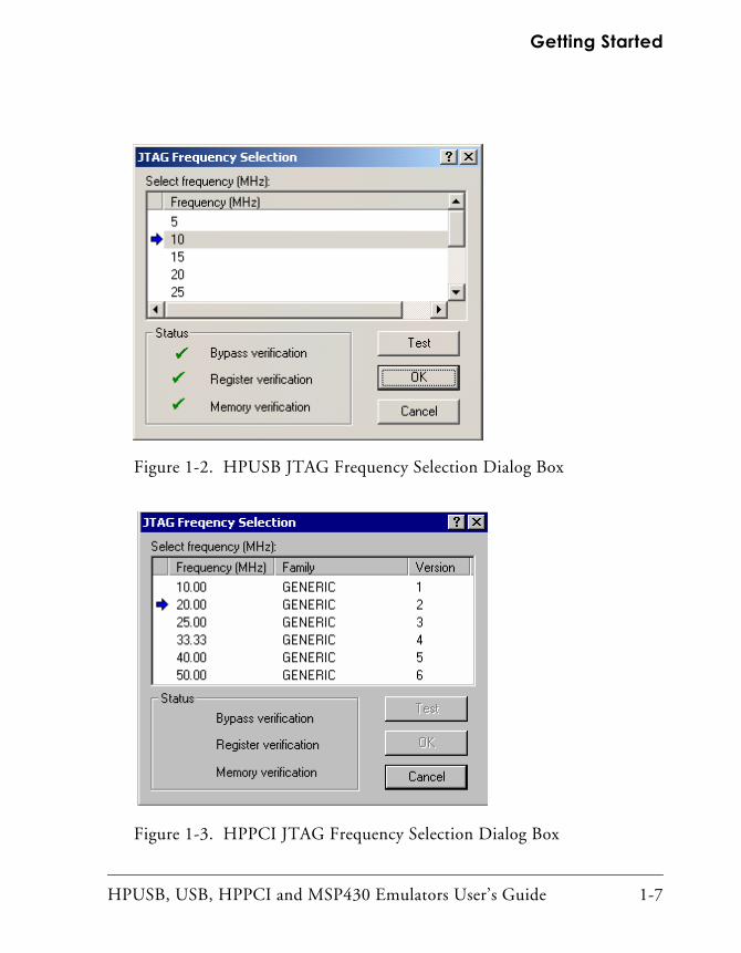
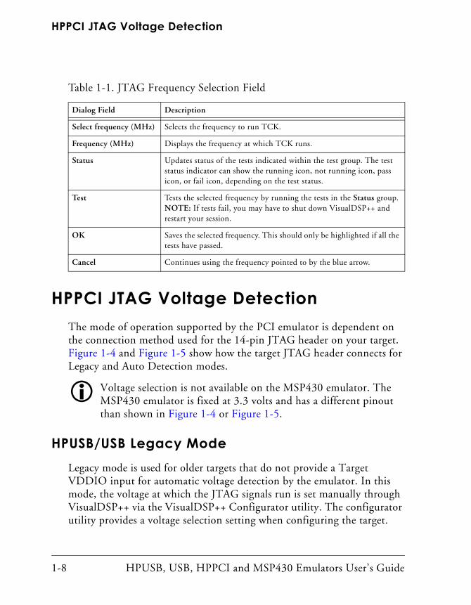
Choosing the JTAG Frequency Selection from the Settings menu in VisualDSP++ opens the JTAG Frequency Selection dialog box shown in Figure 1-2 and Figure 1-3. The dialog box is used to change the rate at which the JTAG Test Clock signal (TCK) runs.
Not all frequencies shown above appear for all processor families. Displayed frequencies depend on the processor family.
The entries in the Status box are the tests that are run when clicking Test on the JTAG Frequency Selection dialog box. The blue arrow points to the frequency currently being used. The arrow does not change after you run the tests because pressing the Cancel button goes back to using the frequency pointed to by the blue arrow. To use a different frequency, select the appropriate frequency from the list and click Test. Clicking OK uses the frequency that is highlighted and that has already been tested.
Table 1-1 lists and describes each of the available options.
If a problems is encountered when launching VisualDSP++ at a certain frequency, delete your session in VisualDSP++ and create a new one. This sets TCK back to the default value of 10 MHz.
1-6 HPUSB, USB, HPPCI and MSP430 Emulators User’s Guide
Getting Started
Figure 1-2. HPUSB JTAG Frequency Selection Dialog Box
Figure 1-3. HPPCI JTAG Frequency Selection Dialog Box
HPUSB, USB, HPPCI and MSP430 Emulators User’s Guide 1-7
HPPCI JTAG Voltage Detection
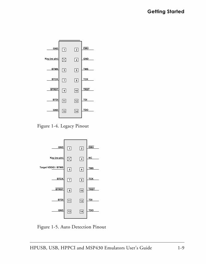
HPPCI JTAG Voltage Detection The mode of operation supported by the PCI emulator is dependent on the connection method used for the 14-pin JTAG header on your target. Figure 1-4 and Figure 1-5 show how the target JTAG header connects for Legacy and Auto Detection modes.
Voltage selection is not available on the MSP430 emulator. The MSP430 emulator is fixed at 3.3 volts and has a different pinout than shown in Figure 1-4 or Figure 1-5.
HPUSB/USB Legacy ModeLegacy mode is used for older targets that do not provide a Target VDDIO input for automatic voltage detection by the emulator. In this mode, the voltage at which the JTAG signals run is set manually through VisualDSP++ via the VisualDSP++ Configurator utility. The configurator utility provides a voltage selection setting when configuring the target.
Table 1-1. JTAG Frequency Selection Field
Dialog Field Description
Select frequency (MHz) Selects the frequency to run TCK.
Frequency (MHz) Displays the frequency at which TCK runs.
Status Updates status of the tests indicated within the test group. The test status indicator can show the running icon, not running icon, pass icon, or fail icon, depending on the test status.
Test Tests the selected frequency by running the tests in the Status group. NOTE: If tests fail, you may have to shut down VisualDSP++ and restart your session.
OK Saves the selected frequency. This should only be highlighted if all the tests have passed.
Cancel Continues using the frequency pointed to by the blue arrow.
1-8 HPUSB, USB, HPPCI and MSP430 Emulators User’s Guide
Getting Started
Figure 1-4. Legacy Pinout
Figure 1-5. Auto Detection Pinout
1 2
4
5 6
7 8
9 10
11 12
13 14
GND
Key (no pin)
EMU
GND
TMS
TCK
TRST
TDI
TDOGND
BTMS
BTCK
BTRST
BTDI
1 2
4
5 6
7 8
9 10
11 12
13 14
GND
Key (no pin)
EMU
GND
TMS
TCK
TRST
TDI
TDOGND
BTMS
BTCK
BTRST
BTDI
1 2
4
5 6
7 8
9 10
11 12
13 14
GND
Key (no pin)
EMU
NC
TMS
TCK
TRST
TDI
TDOGND
Target VDDIO / BTMS
BTCK
BTRST
BTDI
HPUSB, USB, HPPCI and MSP430 Emulators User’s Guide 1-9
HPPCI JTAG Voltage Detection
The HPUSB and USB emulators do not support the Auto Voltage Detection mode.
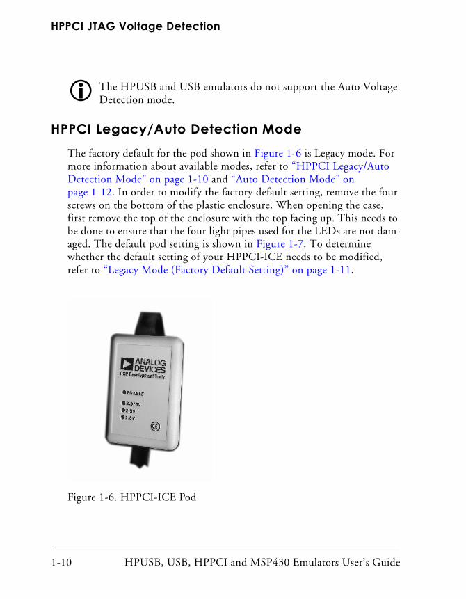
HPPCI Legacy/Auto Detection ModeThe factory default for the pod shown in Figure 1-6 is Legacy mode. For more information about available modes, refer to “HPPCI Legacy/Auto Detection Mode” on page 1-10 and “Auto Detection Mode” on page 1-12. In order to modify the factory default setting, remove the four screws on the bottom of the plastic enclosure. When opening the case, first remove the top of the enclosure with the top facing up. This needs to be done to ensure that the four light pipes used for the LEDs are not dam-aged. The default pod setting is shown in Figure 1-7. To determine whether the default setting of your HPPCI-ICE needs to be modified, refer to “Legacy Mode (Factory Default Setting)” on page 1-11.
Figure 1-6. HPPCI-ICE Pod
1-10 HPUSB, USB, HPPCI and MSP430 Emulators User’s Guide
Getting Started
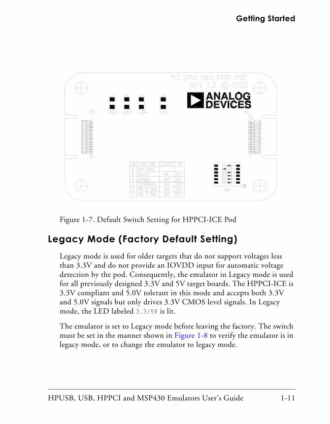
Legacy Mode (Factory Default Setting)Legacy mode is used for older targets that do not support voltages less than 3.3V and do not provide an IOVDD input for automatic voltage detection by the pod. Consequently, the emulator in Legacy mode is used for all previously designed 3.3V and 5V target boards. The HPPCI-ICE is 3.3V compliant and 5.0V tolerant in this mode and accepts both 3.3V and 5.0V signals but only drives 3.3V CMOS level signals. In Legacy mode, the LED labeled 3.3/5V is lit.
The emulator is set to Legacy mode before leaving the factory. The switch must be set in the manner shown in Figure 1-8 to verify the emulator is in legacy mode, or to change the emulator to legacy mode.
Figure 1-7. Default Switch Setting for HPPCI-ICE Pod
HPUSB, USB, HPPCI and MSP430 Emulators User’s Guide 1-11
HPPCI JTAG Voltage Detection
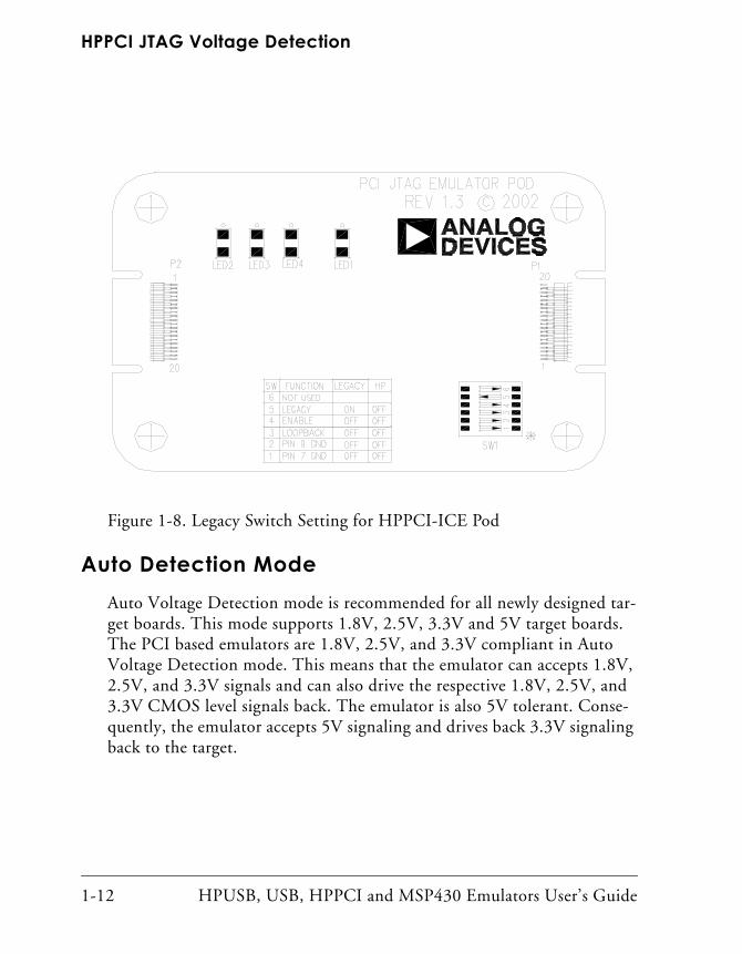
Auto Detection ModeAuto Voltage Detection mode is recommended for all newly designed tar-get boards. This mode supports 1.8V, 2.5V, 3.3V and 5V target boards. The PCI based emulators are 1.8V, 2.5V, and 3.3V compliant in Auto Voltage Detection mode. This means that the emulator can accepts 1.8V, 2.5V, and 3.3V signals and can also drive the respective 1.8V, 2.5V, and 3.3V CMOS level signals back. The emulator is also 5V tolerant. Conse-quently, the emulator accepts 5V signaling and drives back 3.3V signaling back to the target.
Figure 1-8. Legacy Switch Setting for HPPCI-ICE Pod
1-12 HPUSB, USB, HPPCI and MSP430 Emulators User’s Guide
Getting Started
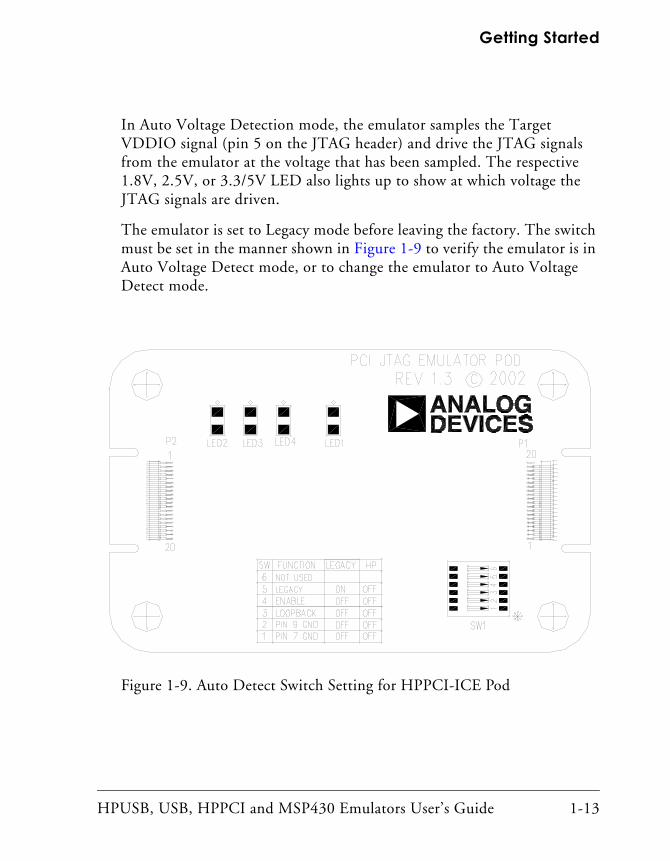
In Auto Voltage Detection mode, the emulator samples the Target VDDIO signal (pin 5 on the JTAG header) and drive the JTAG signals from the emulator at the voltage that has been sampled. The respective 1.8V, 2.5V, or 3.3/5V LED also lights up to show at which voltage the JTAG signals are driven.
The emulator is set to Legacy mode before leaving the factory. The switch must be set in the manner shown in Figure 1-9 to verify the emulator is in Auto Voltage Detect mode, or to change the emulator to Auto Voltage Detect mode.
Figure 1-9. Auto Detect Switch Setting for HPPCI-ICE Pod
HPUSB, USB, HPPCI and MSP430 Emulators User’s Guide 1-13

HPPCI JTAG Voltage Detection
1-14 HPUSB, USB, HPPCI and MSP430 Emulators User’s Guide
2 HARDWARE DESCRIPTION
This chapter describes the hardware design of the USB and PCI based
emulators.LEDs
HPUSB-ICE/USB-ICE LEDsThere are four LEDs located on the enclosure. The following text explains what each LED signifies.
• 1.8V LED – This LED signifies that the ICE drives all signals at 1.8V compliant levels.
• 2.5V LED – This LED signifies that the ICE drives all signals at 2.5V compliant levels.
• 3.3/5V LED – This LED signifies that the ICE drives all signals at 3.3V compliant levels.
• ENABLE – This LED is turned on when a VisualDSP++ session is running. The LED shuts off every time the VisualDSP++ session is closed. When the LED is off, it signifies that all outputs of the pod logic connected to the target have been tri-stated. Tri-stating the outputs of the pod when VisualDSP++ is inactive prevents the tar-get processor from entering an unknown state during the target power up sequencing.
HPUSB, USB, HPPCI and MSP430 Emulators User’s Guide 2-1
LEDs
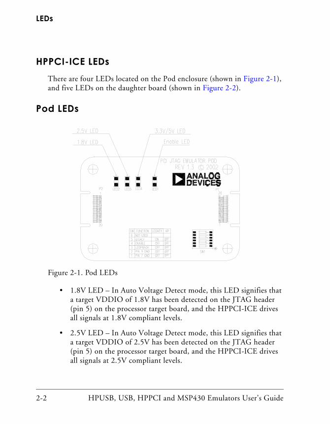
HPPCI-ICE LEDsThere are four LEDs located on the Pod enclosure (shown in Figure 2-1), and five LEDs on the daughter board (shown in Figure 2-2).
Pod LEDs
• 1.8V LED – In Auto Voltage Detect mode, this LED signifies that a target VDDIO of 1.8V has been detected on the JTAG header (pin 5) on the processor target board, and the HPPCI-ICE drives all signals at 1.8V compliant levels.
• 2.5V LED – In Auto Voltage Detect mode, this LED signifies that a target VDDIO of 2.5V has been detected on the JTAG header (pin 5) on the processor target board, and the HPPCI-ICE drives all signals at 2.5V compliant levels.
Figure 2-1. Pod LEDs
2-2 HPUSB, USB, HPPCI and MSP430 Emulators User’s Guide
Hardware Description
• 3.3/5V LED – In Auto Voltage Detect mode, this LED signifies that a target VDDIO of 3.3V or 5V has been detected on the JTAG header (pin 5) on the processor target board, and the HPPCI-ICE drives all signals at 3.3V compliant levels. In Legacy mode, this LED is automatically powered, and pin 5 of the JTAG header on the target board is not used to detect the target VDDIO voltage.
• ENABLE – This LED is turned on when a VisualDSP++ session is running. This LED shuts off every time the VisualDSP++ session is closed. When this LED is off, it signifies all outputs of the pod logic connected to the target have been tri-stated. Tri-stating the outputs of the pod when VisualDSP++ is inactive prevents the tar-get processor from entering an unknown state during the target power up sequencing.
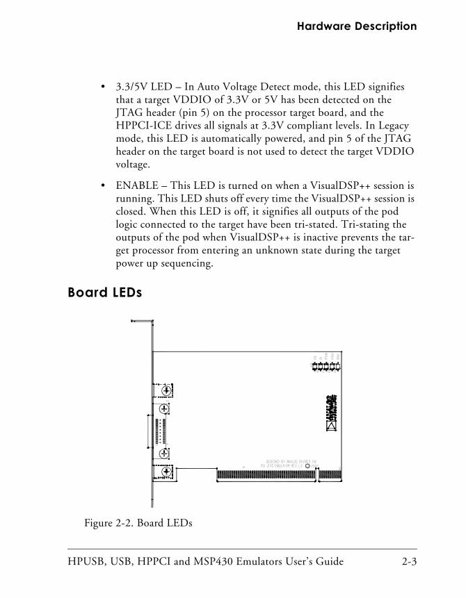
Board LEDs
Figure 2-2. Board LEDs
HPUSB, USB, HPPCI and MSP430 Emulators User’s Guide 2-3
Designing Custom Processor Boards
• VCC – This LED signifies that the board is receiving 5V power. If this LED is not active, the HPPCI-ICE does not function properly.
• 3V – This LED signifies that the board is receiving 3.3V power. If this LED is not active, the HPPCI-ICE does not function properly.
• FPGA[1:0] – These two LEDs are used for factory purposes only.
• DONE – This LED is activated when a VisualDSP++ session is started. The LED should remain active even after the respective session has been terminated. The LED shuts off and re-activates at the beginning of every new VisualDSP++ session.
MSP430-ICE LEDThere is one LED located on the enclosure.
ENABLE – This LED is turned on when a VisualDSP++ session is run-ning. The LED shuts off every time the VisualDSP++ session is closed. When this LED is off, it signifies all outputs of the pod logic connected to the target have been tri-stated. Tri-stating the outputs of the pod when VisualDSP++ is inactive prevents the target processor from entering an unknown state during the target power up sequencing.
Designing Custom Processor BoardsWhen designing a custom processor board using ADI DSPs, special care must be taken to ensure that the JTAG interface is designed and laid out correctly. If the board is not designed correctly, communication via the JTAG port may not work. Another side effect can be that the interface works, but the user is not able to run at the highest possible JTAG clock frequency. The JTAG clock frequency is dependant on the particular Ana-log Devices processor, as well as the delay characteristics of the custom processor board.
2-4 HPUSB, USB, HPPCI and MSP430 Emulators User’s Guide
Hardware Description
To ensure that the custom board’s JTAG interface is designed and laid out correctly, refer to the EE-68 found at http://www.analog.com/Uploaded-
Files/Application_Notes/42866710583EE068.pdf.
Mechanical Specifications
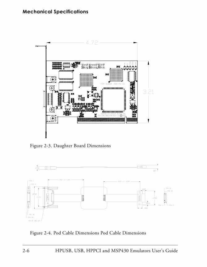
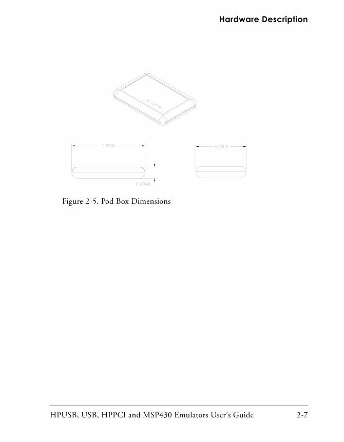
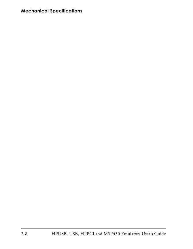
HPPCI-ICEThe HPPCI-ICE consists of a daughter board and a pod cable. The system is compliant with revision 2.2 of the PCI specification and plugs into 5V only motherboards. It uses only the 5V from the PC’s PCI slot. The pod cable consists of a small PCB that has a multi-conductor cable soldered at each end. The multi-conductor cable is constructed with individual coax-ial cables that are encapsulated by shield ground. The PCB in the pod is fully enclosed in a copper-sprayed plastic enclosure. The multi-conductor cables and copper spray reduce system noise and electromagnetic interfer-ence. The mechanical dimensions of the daughter board, pod cable assembly, and pod enclosure are shown in Figure 2-3, Figure 2-4, and Figure 2-5, respectively. Unless specified, all dimensions are in inches.
HPUSB, USB, HPPCI and MSP430 Emulators User’s Guide 2-5
Mechanical Specifications
Figure 2-3. Daughter Board Dimensions
Figure 2-4. Pod Cable Dimensions Pod Cable Dimensions
2-6 HPUSB, USB, HPPCI and MSP430 Emulators User’s Guide
Hardware Description
Figure 2-5. Pod Box Dimensions
HPUSB, USB, HPPCI and MSP430 Emulators User’s Guide 2-7
Mechanical Specifications
2-8 HPUSB, USB, HPPCI and MSP430 Emulators User’s Guide
3 SUPPORT
Analog Devices provides free technical support.
Technical SupportFor technical support, you may contact the Analog Devices DSP Tools Technical Support group in any of the following ways.
• Fill out the DSP Tools Technical Support Web site form athttp://forms.analog.com/Form_Pages/DSP/tools/con-
tactDSP.asp
• Send a description of the problem by e-mail [email protected]
• Call the customer support hotline at 1-800-ANALOG-D (1-800-262-5643 U.S.A. only).
For direct support of the Analog Devices processors, call the Analog Devices DSP Applications Engineering group at 1-800-ANALOG-D or email [email protected].
Quality AssuranceAnalog Devices is committed to providing quality products and services. To continually provide this quality, please contact our Quality Assurance Department directly if you have any concerns at (603) 883-2430, Monday
HPUSB, USB, HPPCI and MSP430 Emulators User’s Guide 3-1

Quality Assurance
through Friday during normal business hours, or via e-mail at [email protected]. Our Quality Assurance manager will listen to your concerns and provide a timely and effective solution.
3-2 HPUSB, USB, HPPCI and MSP430 Emulators User’s Guide
4 REFERENCES
This section describes documentation resources helpful in your applica-
tion development.• For information on designing the interface between an Analog Devices SHARC processor and the emulation header on your cus-tom processor target board, refer to the latest version of Analog Devices EE-68 found athttp://www.analog.com/Uploaded-
Files/Application_Notes/42866710583EE068.pdf.
• For information on the architecture and system interface of the ADI processor, refer to the appropriate Analog Devices processor’s Hardware Reference.
• For ADSP timing specification and other hardware design informa-tion, refer to the appropriate processor’s Data Sheet.
• For complete information on software development tools (assem-bler, compiler, linker, and so on), refer to the documentation included with VisualDSP++. This information is available in printed format, online help, and online in PDF format.
• For information about your development platform, refer to your operating system manuals and hardware system manuals.
HPUSB, USB, HPPCI and MSP430 Emulators User’s Guide 4-1
• For information about digital signal processing theory and applica-tions, you may wish to consult:
Higgins. Digital Signal Processing In VLSI. Prentice-Hall, 1990.Oppenheim and Schafer. Digital Signal Processing. Pren-tice-Hall, 1975.
4-2 HPUSB, USB, HPPCI and MSP430 Emulators User’s Guide
I INDEX
Numerics Device Manager window, 1-4
1.8V LED, 2-1, 2-22.5V LED, 2-1, 2-23.3/5V LED, 2-1, 2-3
Aassembly, 1-2attaching JTAG cable, 1-5auto detection mode, 1-12
Bboard LEDs, 2-3
Ccables, 1-2closing a session, 2-1CMOS signals, 1-12Configurator utility, 1-8connecting
pod cable to target board, 1-5USB cable, 1-3
contents, emulator package, 1-2customer support, -xcustom processor boards, 1-5, 2-4
Ddata sheets, 4-1default setting, 1-10designing custom boards, 2-4
digital signal processing theory, 4-2documentation resources, 4-1drivers, 1-4
EEE-68, 1-5, 2-5enable LED, 2-1, 2-3, 2-4
Ffactory default setting, 1-10, 1-11frequency, 1-6, 1-8, 2-4full/high speed USB port, -viii, -ix, 1-2
Hhardware
description, 2-1references, 4-1
high-speed USB device, -viiHPPCI emulators
attaching cable, 1-5installing, 1-3package contents, 1-2
HPPCI-ICEJTAG voltage detection, 1-8LEDs, 2-2legacy mode, 1-10mechanical specifications, 2-5voltage support, -viii
HPUSB, USB, HPPCI and MSP430 Emulators User’s Guide I-1
INDEX
Iinstallation tasks, 1-3IOVDD input, 1-11IO voltage, -vii, -viii, -ix
JJTAG
clock frequency, -viii, 1-6, 2-4see also TCK
daughter card, 1-2frequency selection, 1-6, 1-8header, 1-5, 1-8, 1-13, 2-4port, 2-4signals, 1-8, 1-13voltage detection, 1-8
JTAG Frequency Selection dialog box, 1-6
LLEDs, 2-1, 2-2
1.8V LED, 2-1, 2-22.5V LED, 2-1, 2-23.3/5V LED, 2-1, 2-3enable LED, 2-1HPPCI-ICE, 2-2HPUSB/USB ICE, 2-1MSP430-ICE, 2-4
legacy mode, 1-11
Mmechanical specifications, 2-5MSP430-ICE
also see USB based emulatorsattaching cable, 1-5LED, 2-4voltage support, -ix
multiprocessor support, -vii, -viii
Ooperating systems, 1-2
PPC configuration, 1-2PCI based emulators
see HPPCI-ICEPCI slot, 1-2plug-n-play, -vii, -viii, -ixpod
assembly, 1-2cable, 1-5LEDs, 2-2logic, 2-1
Qquality assurance, 3-1
Rrestarting sessions, 1-8
Ssaving selected frequency, 1-8status, 1-8support
line, 3-1web site, 3-1
Ttechnical support, 3-1Test Clock signal (TCK), 1-6, 1-8testing
JTAG frequency, 1-8testing JTAG frequency, 1-8
I-2 HPUSB, USB, HPPCI and MSP430 Emulators User’s Guide
INDEX
UUSB based emulators
attaching cable, 1-5installing, 1-3LEDs, 2-1legacy mode, 1-8package contents, 1-2USB port, 1-2voltage support, -viii
USB port, 1-3
VVDDIO signal, 1-8, 1-13verifying driver installation, 1-4VisualDSP++, -vii, 1-2, 1-3, 1-8
documentation, 4-1session, 2-1
voltagecompliance, -viii, 1-12compliance levels, 1-12
HPUSB, USB, HPPCI and MSP430 Emulators User’s Guide I-3