Embed Size (px)
Citation preview

51-3951
1
HR Series Hydraulic Windrow Sweepers
800-456-7100 www.paladinlcg.com Sweepster: 2800 N. Zeeb Road, Dexter, MI, 48130, United States of America Copyright ©
Serial NumberManual Number: 51-3951Release Date: November, 2012Serial Number 0815001 and UP

51-39512
Notes

51-3951
3
Table of Contents
Installation & Safety .............................................................................................................. 5-13 Introduction .......................................................................................................................... 5 Safety ................................................................................................................................ 6-9 Product Information ....................................................................................................... 10-11 Operation and Maintenance ............................................................................................... 12-18Service & Troubleshooting.................................................................................................. 19-21Parts ................................................................................................................................... 22-39 Brush Head Frame ............................................................................................................. 22 Core Assemblies ................................................................................................................ 23 Shaft Assembly .................................................................................................................. 24 Hydraulic Assemblies .................................................................................................... 25-26 Motor Bucket ...................................................................................................................... 27 Brush Head Labels............................................................................................................. 28 Linkage............................................................................................................................... 29 Hydraulic Tank .................................................................................................................... 30 Pump/Hose Assembly ........................................................................................................ 31 Hood Kits....................................................................................................................... 32-33 Dust Suppression .......................................................................................................... 34-35 Hose Kit 3Pt Tank ............................................................................................................... 36 Sight Indicator Kits ............................................................................................................. 37Appendix............................................................................................................................. 38-44 TorqueSpecifications .................................................................................................... 38-40 Warranty ............................................................................................................................. 41

51-39514
Notes
51-3951
5
INTRODUCTION
Purpose of Sweeper
This sweeper is designed solely for the use in construction cleanup, road maintenance and similar operations. Use in any other way is considered contrary to the intended use. Compliance with and strict adherence to operation, service and repair conditions,asspecifiedbythemanufacturer,arealso essential elements of the intended use.
Contacting Sweepster
If you have any questions about information in this manual or need to order parts, please call, write, fax or e-mail SWEEPSTER.
Sweepster2800 North Zeeb RoadDexter, Michigan 48130
Phone: (734)-996-9116 - (800)-456-7100Fax: (734) 996-9014
e-mail: [email protected]
For help with installation, operation or maintenance procedures, contact our Technical Service Department. Direct product questions and parts orders to our Sales Department.
When ordering parts or accessories, be prepared to give the following information:
•Sweepermodel,serialnumberanddateof purchase•Primemover,makeandmodel•Partnumber,descriptionandquantity
Terms Used in Manual
Right-hand, left-hand, front and rear are determined from the operator’s perspective (either the operator’s seat or standing behind a walk-behind unit), facing forward in the normal operating position.
Warranty
Tovalidatethewarrantyforthisunit,filloutthewarranty card or warranty pages located in the back of this manual. Then send this information to SWEEPSTER.
SAFETY STATEMENTS
DANGER! THIS STATEMENT IS USED WHERE SERIOUS INJURY OR DEATH WILL RESULT IF THE INSTRUCTIONS ARE NOT FOLLOWED PROPERLY.
WARNING! THIS STATEMENT IS USED WHERE SERIOUS INJURY OR DEATH COULD RESULT IF THE INSTRUCTIONS ARE NOT FOLLOWED PROPERLY.
CAUTION! THIS STATEMENT IS USED WHERE MINOR INJURY COULD RESULT IF THE INSTRUCTIONS ARE NOT FOLLOWED PROPERLY.
NOTICE! THIS STATEMENT IS USED WHERE EQUIPMENT OR PROPERTY DAMAGE COULD RESULT IF THE INSTRUCTIONS ARE NOT FOLLOWED PROPERLY.
THIS SYMBOL BY ITSELF OR USED WITH A SAFETY SIGNAL WORD THROUGHOUT THIS MANUAL IS USED TO CALL YOUR ATTENTION TO INSTRUCTIONS INVOLVING YOUR PERSONAL SAFETY OR THE SAFETY OF OTHERS. FAILURE TO FOLLOW THESE INSTRUCTIONS CAN RESULT IN INJURY OR DEATH.

51-39516
GENERAL SAFETY PRECAUTIONS
WARNING! READ MANUAL PRIOR TO INSTALL
Improper installation, operation, or maintenance of this equipment could result in serious injury or death. Operators and maintenance personnel should read this manual as well as all manuals related to this equipment and the prime mover thoroughly before beginning installation, operation, or maintenance. FOLLOW ALL SAFETY INSTRUCTIONS IN THIS MANUAL AND THE PRIME MOVERS MANUAL.
WARNING! READ AND UNDERSTAND ALL SAFETY STATEMENTS
Read all safety decals and safety statements in all manuals prior to operating or working on this equipment. Know and obey all OSHA regulations, local laws and other professional guidelines for your operation. Know and follow good work practices when assembling, maintaining, repairing, mounting, removing or operating this equipment.
KNOW YOUR EQUIPMENT Know your equipment’s capabilities,
dimensions and operations before operating. Visually inspect your equipment before you start, and never operate equipment that is not in proper working order with all safety devices intact. Check all hardware to assure it is tight. Make certain that all locking pins, latches, and connection devices are properly installed and secured. Remove and replace any damaged, fatigued or excessively worn parts. Make certain all safety decals are in place and are legible. Keep decals clean, and replace them if they become worn and hard to read.
GENERAL SAFETY PRECAUTIONS
WARNING! PROTECT AGAINST FLYING DEBRIS
Always wear proper safety glasses, goggles or a face shield when driving pins in or out or when operationcausesdust,flyingdebris,or any other hazardous material.
WARNING! LOWER OR SUPPORT RAISED EQUIPMENT
Do not work under raised booms without supporting them. Do not use support material made of concrete blocks, logs, buckets, barrels or any other material that could suddenly collapse or shift positions. Make sure support material is solid, not decayed, warped, twisted, or tapered. Lower booms to ground level or onto blocks. Lower booms and attachments to the ground before leaving the cab or operator’s station.
WARNING! USE CARE WITH HYDRAULIC FLUID PRESSURE
Hydraulicfluidunderpressurecan penetrate the skin and cause serious injury or death. Hydraulic leaks under pressure may not be visible. Before connecting or disconnecting hydraulic hoses, read your prime movers operator’s manual for detailed instructions on connecting and disconnecting hydraulichosesorfittings.
•Keep unprotected body parts, such as face, eyes, and arms as far away as possible from a suspected leak. Flesh injected withhydraulicfluidmaydevelop gangrene or other permanent disabilities. •Ifinjuredbyinjectedfluid,seea doctor at once. If your doctor is not familiar with this type of injury, ask him to research immediately to determine proper treatment.

51-3951
7
•Wear safety glasses, protective clothing, and use a sound piece of cardboard or wood when searching for hydraulic leaks. DO NOT USE YOUR HANDS! SEE ILLUSTRATION.
WARNING! DO NOT MODIFY MACHINE OR ATTACHMENTS
Modificationsmayweakentheintegrity of the attachment and may impair the function, safety, life and performance of the attachment. When making repairs, use only the manufacturer’s genuine parts, following authorized instructions. Other parts may be substandard infitandquality.NevermodifyanyROPS (Roll Over Protection
WARNING! SAFELY MAINTAIN AND REPAIR EQUIPMENT
•Donotwearlooseclothing,orany accessories that can catch in moving parts. If you have long hair, cover or secure it so that it does not become entangled in the equipment. •Workonalevelsurfaceinawell-lit area. •Useproperlygroundedelectrical outlets and tools. •Usethecorrecttoolforthejobat hand. Make sure they are in good condition for the task required. •Weartheprotectiveclothingequipmentspecifiedbythetool manufacturer.
WARNING! SAFELY OPERATE EQUIPMENT Do not operate equipment until you
arecompletelytrainedbyaqualifiedoperator in how to use the controls, know its capabilities, dimensions, and all safety requirements. See your prime movers manual for these instructions.
•Keepallstepplates,grabbars, pedals, and controls free of dirt, grease, debris, and oil. •Neverallowanyonetobearound the equipment when it is operating. •Donotallowridersonthe attachment or the prime mover. •Donotoperatetheequipment from anywhere other than the correct operators position. •Neverleaveequipment unattended with the engine running or with this attachment in a raise position. •Donotalterorremoveanysafety feature from the prime mover or this attachment. •Knowyourworksitesafetyrulesaswellastrafficrulesandflow. When in doubt on any safety issue, contact your supervisor or safety coordinator for an explanation.
WARNING! EXPOSURE TO RESPIRABLE
CRYSTALLINE SILICA DUST ALONG WITH OTHER
HAZARDOUS DUSTS MAY CAUSE SERIOUS OR FATAL RESPIRATORY DISEASE.
It is recommended to use dust suppression, dust collection and if necessary personal protective equipment during the operation of any attachment that may cause high levels of dust.
GENERAL SAFETY PRECAUTIONS GENERAL SAFETY PRECAUTIONS

51-39518
Item Part Qty Description
1. 41043 1 Decal, Warning, Hazardous Dust3. 50-0643 2 Label, Tie Down Point4. 50-0721 4 Label, Warning, Crush Hazard5. 50-0722 1 Label, Warning, Misuse Hazard6. 50-0724 1 Label, Warning, High Pressure Fluid Hazard7. 50-0726 2 Label, Warning, Flying Objects & Entanglement
7
7
3
4
16
5
4
24
SAFETY SIGNS & LABELS
SAFETY SIGNS & LABELSThereareseveralspecificsignsonthissweeper.Theexact location of the hazards and description of the hazards are reviewed.
Placement or replacement of Safety Signs
1. Cleantheareaofapplicationwithnonflammablesolvent, and then wash the same area with soap and water.
2. Allow the surface to fully dry.
3. Remove the backing from the safety sign, exposing the adhesive surface.
4. Apply the safety sign to the position shown in the diagram above and smooth out any bubbles.
Instructions
1. Keep all safety signs clean and legible.
2. Replace all missing, illegible, or damaged safety signs.
3. Replacement parts, for parts with safety signs attached, must also have safety signs attached.
4. Safety signs are available, free of charge, from your dealer or from SWEEPSTER.
Serial Tag Location

51-3951
9
3. 50-0643
6. 50-0724
4. 50-0721
5. 50-0722
7. 50-0726
1. 41043
SAFETY SIGNS & LABELS

51-395110
29.7 52.7
82.4
42.4
84.8
Maxim
um Length at 0° A
rticulationM
aximum
Length at Full Articulation
Product InformationSection
SpecificationsandModelViews
29.7 52.7
82.4
42.4
84.8
Maximum Width at Full Articulation
Maximum Width at 0° Articulation HR Brush HeadApproximate Weight Single Motor Dual Motor
677 lbs 720 lbs 6 Ft 708 lbs 752 lbs 7 Ft 739 lbs 783 lbs 8 Ft
Maximum Length at 0º Articulation
74 inches
Maximum Width at 0º Articulation
84.8 inches 6 Ft96.8 inches 7 Ft108.8 inches 8 Ft
Maximum Length at Full Articulation
86.7 inches 6 Ft90.6 inches 7 Ft94.5 inches 8 Ft
Maximum Width at Full Articulation
84.5 inches 6 Ft93.7 inches 7 Ft103 inches 8 Ft
Sweeping Width at 0º Articulation
72 inches 6 Ft84 inches 7 Ft96 inches 8 Ft
Sweeping Width at Full Articulation
54.3 inches 6 Ft63.5 inches 7 Ft 73 inches 8 Ft
Range of Hydraulic Oil Flow
14-25 gpm Single Motor 22-36 gpm Dual Motor
Maximum Hydraulic Oil Pressure
3000 psi 3500 psi

51-3951
11
Storage
NOTICE! Do not store the sweeper with weight on the brush. Weight will deform the bristles, destroying the sweeping effectiveness. To avoid this problem, place the sweeper on blocks or use storage stands.
Do not store polypropylene brushes in direct sunlight. The material can deteriorate and crumble before the bristles are worn out.
Keeppolypropylenebrushmaterialawayfromintenseheatorflame.
General Storage:
Storage:
• Cleantheunitthoroughly,removingallsnow,dirtandgrease.• Inspectforvisiblesignsofwear,breakageordamage.Orderanypartsrequiredandmakethe
necessary repairs to avoid delays upon removal from storage.• Tightenloosenuts,capscrewsandhydraulicconnections.• Coatexposedportionsofthecylinderrodswithgrease.• Lubricategreasefittings.• Sealhydraulicsystemfromcontaminantsandsecureallhydraulichosesoffthegroundtohelpprevent
damage.• Storeunitinadryandprotectedplace.Leavingtheunitoutsidewillmateriallyshortenitslife.
Additional Precautions for Long Term Storage:
• Touchupallunpaintedsurfaceswithpainttoavoidrust.• Inflatetirestorecommendedtirepressure.• Fillfueltankandhydraulicoiltanktomaximum.• Checkantifreezepropertiesanddrainfluidsasappropriate.
Removal from Storage:
• Removecover.• Washunitandreplaceanydamageand/ormissingparts.• Lubricategreasefittings.• Checkhydraulichosesfordamageandreplaceasnecessary.

51-395112
Sweeping
To sweep:
1. Swing the brush head assembly the direction that you want to direct debris.
2. Engage the brush and then lower it to the ground.
3. Increase prime mover engine rpm to sweeping speed. 4. Travel forward at 2-3 mph (3-5 kph) or less.
CAUTION - Avoid sweeper damage. Reduce travel
speed to avoid hitting immovable objects.
Before Each Use
Perform daily maintenance as indicated in MaintenanceSchedule.
Run the prime mover and sweeper at a slow idle. Check for hydraulic leaks or other problems and makecorrections, if necessary, before using the sweeper. See “Hydraulic Inspection Guideline” .
WARNING! Avoid serious injury. Check for large objects that could
harm the operator or others if thrown by the sweeper. Remove these items before operating.
Directing Debris
Carry the sweeper low to the ground so that the operator has good visibility and stability. Avoid any sudden movements.
Avoid excessive downward pressure on the brush sections to prevent excessive wear. A two to four inch widepatternissufficientformostapplications.Ensurethat the adjustment bolts are equally adjusted in order to prevent an uneven wear pattern. To adjust brush pattern see “Adjusting Brush Pattern”. Direct debris by angling the brush head in that direction.
Observe wind direction. Sweeping with the wind makes sweeping more effective and helps keep debris off the operator.
The terms swing and angle are used interchangeably.
Hydraulic Angle
1. Start the prime mover.
2. Position the brush head at the desired angle by using the valve control for the swing function.
During Use
Operating Tips
NOTICE - Avoid sweeper damage. Do not ram into piles. Use an appropriate attachment for this type of job.
Brush, Engine & Travel Speeds
Vary brush, engine and travel speeds to match sweeping conditions.
Large Areas
When sweeping a large area, such as a parking lot, make a path down the middle and sweep to both sides. This reduces the amount of debris that the sweeper must sweep to one side.
Snow
Fast brush speeds and slow travel speeds are needed to sweep snow effectively. Start at 3/4 throttle and the lowest gear of the prime mover. For wet and/or deep snow, increase to almost full throttle. This helps keep snow from packing up inside the brush hood.
In deep snow you may need to make multiple passes to get down to a clean surface.
To keep snow from blowing back onto a swept area, always sweep so the wind is at your back.

51-3951
13
CAUTION! Avoid Injury. Before adjusting the sweeper, always turn off the sweeper and the prime mover engine and remove the key.
1. Movethetractortoaflat,pavedsurface.
2. Verify that the pressure is correct in tractor tires. Refer to the tractor operator’s manual.
3. Make sure that the tractor parking brake is on; start the tractor and sweeper. Lower the brush head so the brush is 2 inches (51mm) above the ground. Adjust sweeper to be level left and right. To check swing level use a bubble level and refer tofigure2.
4. Check to see if broom is level when angled. Swing the sweeper to the right; stop the tractor. Then, on both sides of the sweeper measure from the groundtothebottomofthebrushframe(figure1).
5. Start the tractor. Swing the sweeper to the left; stop the tractor. then, on both sides of the sweeper measure from the ground to the bottom of the brush frame.
6. If measurements in step 4 and 5 are all equal, the sweeper is level.
Ifnot,makeadjustmentsasshowninfigures3-5.
Leveling
Level the sweeper for even brush wear and effective use.
suppression kit or plan sweeping for days when it is overcast and humid or after it has rained. Also, sweep so the wind blows at your back.
Low brush speeds and moderate travel speeds work best for cleaning debris from hard surfaces. Brush speeds that are too fast tend to raise dust because of the aggressive sweeper action.
To sweep gravel, use just enough brush speed to “roll” the gravel, not throw it.
Heavy Debris
Travel slowly - 1-2 mph.
Sweep a path less than the full width of the sweeper.
High
Low
Left
RightSwung
Swung
Swung
Swung
High
High High
Low
LowLow
Right
Left
Dirt & Gravel
To keep dust at a minimum, use the optional dust
figure1.
figure3.
figure2.
figure4.
figure5.
To correct this leveling problem, turn nuts on adjustment links away from the tractor
To correct this leveling problem, turn nuts on adjustment links toward from the tractor
1 41 8
16

51-395114
Setting Brush Pattern
A properly adjusted brush offers the best sweeperperformance. To check the brush pattern:
1.Movethesweepertoadusty,flatsurface.
2. Set the prime mover’s parking brake and leave the engine running.
3. Start the sweeper at a slow speed: lower it so the bristle tips touch the ground. Run the sweeper in a stationary position for 10 seconds.
4. Raise the sweeper and back away; switch off the engine and remove the key. The brush pattern left in the dust should be 2-4 inches (51-102 mm) wide, running the length of the brush. (Compare the swept areawith(figure1)
Adjusting the Brush Pattern
1. Lower the sweeper.
2. To adjust brush pattern rotate the cylinder rod ontheliftrodassembly(figure2).Turningtherod counter clockwise will lessen brush pressure and decrease the width of the brush pattern. Turning the rod clockwise will increase pressure on the brush and widen brush pattern. To relieve pressure from the rod assembly when adjusting lower the brush head completely.
Swept Area
2-4 in.(51-102 mm)
Figure 1
Figure 2
Worn Section Standard ReferenceInformation
Section OD, New
Ring ID SectionOD, Worn
ExposedBristle, Worn
BristleLength
ExposedBristle, New
24 6.38 17 3.8 8.50 7.526 8.00 18 4.0 9.00 8.032 10.00 22 5.0 11.00 10.036 10.00 24 6.0 13.00 12.036 10.63 25 6.0 12.69 11.446 19.38 34 6.0 13.31 12.1

51-3951
15
Maintenance Schedule
Procedure Before Each Use
After Each Use
100 Hours
500 Hours
See Prime Mover Manual
Brush head assembly - LevelBrush pattern - Check (See Pattern Adj. Section)Cylinders - Retract rodsFilter, air, prime mover- CleanFittings/hoses, hydraulic - Check for leaks/tighten Check for damageFittings, zerk - Grease (See lubrication points)Oil, hydraulic - Check levelHardware - Check for tightnessRemovehydraulicoilfilter - ReplaceWash Unit - Remove grease and debris from all components, especially hoses, tank, motor, pump

51-395116
Maintenance Record
Use this log to record maintenance performed on the sweeper.
Date Maintenance Procedure Performed Performed by Comments
51-3951
17
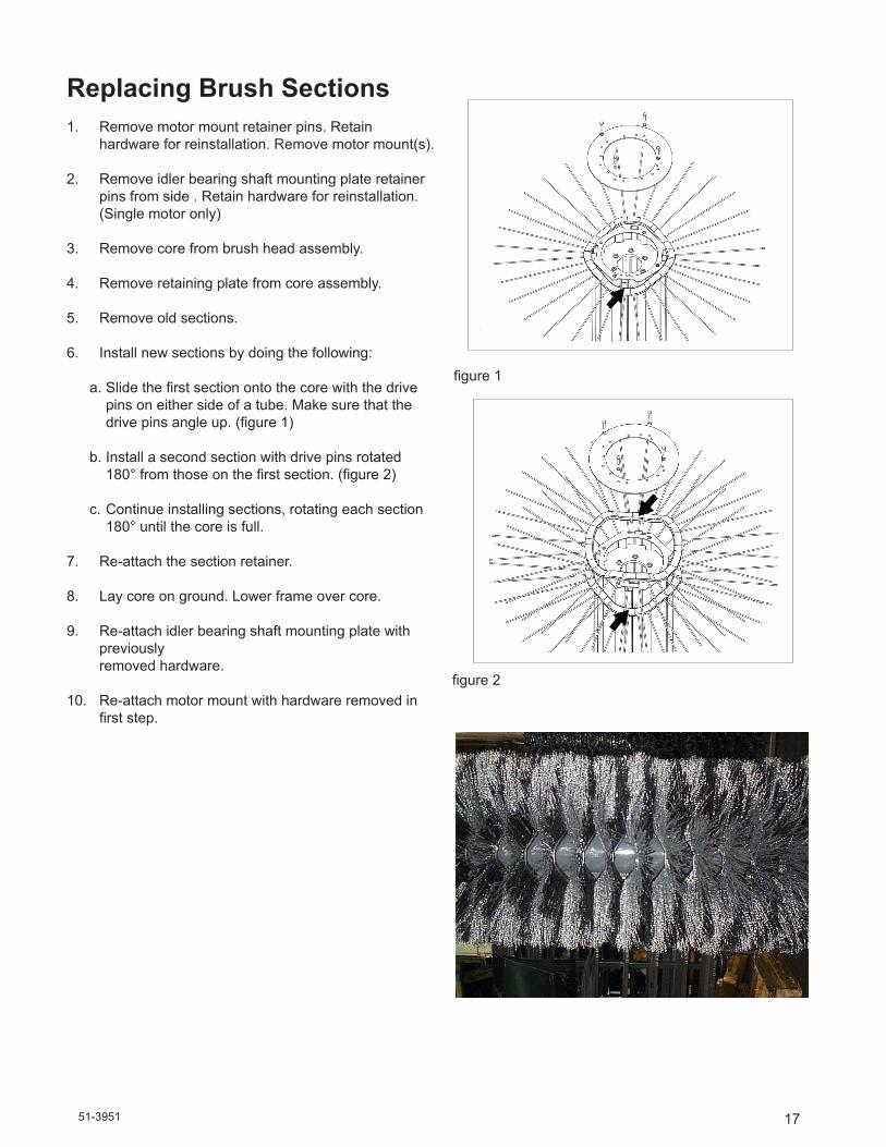
Replacing Brush Sections1. Remove motor mount retainer pins. Retain
hardware for reinstallation. Remove motor mount(s).
2. Remove idler bearing shaft mounting plate retainer pins from side . Retain hardware for reinstallation. (Single motor only)
3. Remove core from brush head assembly.
4. Remove retaining plate from core assembly.
5. Remove old sections.
6. Install new sections by doing the following:
a.Slidethefirstsectionontothecorewiththedrive pins on either side of a tube. Make sure that the drivepinsangleup.(figure1)
b. Install a second section with drive pins rotated 180°fromthoseonthefirstsection.(figure2)
c. Continue installing sections, rotating each section 180° until the core is full.
7. Re-attach the section retainer.
8. Lay core on ground. Lower frame over core.
9. Re-attach idler bearing shaft mounting plate with previously
removed hardware.
10. Re-attach motor mount with hardware removed in firststep.
figure1
figure2
51-395118
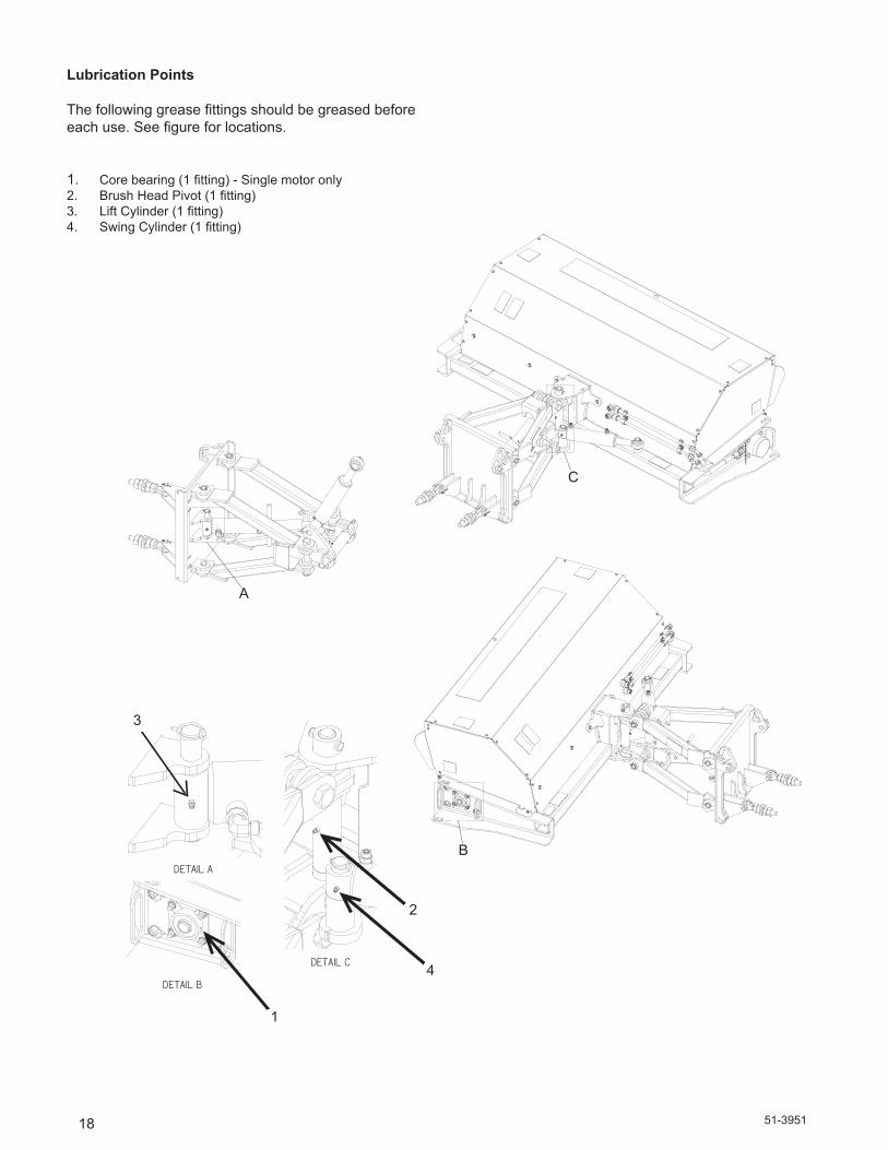
Lubrication Points
Thefollowinggreasefittingsshouldbegreasedbeforeeachuse.Seefigureforlocations.
1. Corebearing(1fitting)-Singlemotoronly2. BrushHeadPivot(1fitting)3. LiftCylinder(1fitting)4. SwingCylinder(1fitting)
A
DETAIL A
B
DETAIL B
C
DETAIL C
A
DETAIL A
B
DETAIL B
C
DETAIL C
A
DETAIL A
B
DETAIL B
C
DETAIL C
C
B
A
3
1
2
4

51-3951
19
Brush Head Troubleshooting
Problem Possible Cause Possible SolutionBrush rotates wrong direction Hoses installed incorrectly Switch hoses at brush head tubes
Brush slows or stops when sweeping
Brush pattern too wide Adjust pattern to 2-4 inches (51-101mm) wide: see Maintenance: Adjusting Brush Pattern
Travel speed too fast Travel no more than 5mph (8 kph) while sweeping (2-3mph recommended)
Trying to sweep too much material at once
Make several passes with sweeper
Relief pressure set too low Set relief pressure to 2000psi (138.0 bars)
Filter plugging Changeorcleanhydraulicoilfilter
Brush head assembly “bounces” during sweeping
Travel speed too fast and/or brush speed too slow
Find correct combination of ground and brush speeds: do not travel at more than 5 mph (8 kph)
Brush wears into cone shape Sweeper is not level Level sweeper before each use: see Maintenance: Leveling
Tires on prime mover at different pressures or are different sizes
Check tire sizes and rating: make corrections as necessary
Brush wears very quickly Brush pattern too wide Adjust brush pattern to 2-4 inches (51-101mm) wide: see Maintenance: Setting Brush Pattern

51-395120
Hydraulic Cylinders - Lift & Swing Troubleshooting
Problem Possible Cause Possible SolutionHydraulic cylinder neither extends nor retracts
Control rods not connected or are binding
Check control rod linkage; make sure all parts are connected and arenotbinding;fixifnecessary
Hydraulic oil level too low Fill tank to 2-3 inches (51-76mm) from top of tank with ISO VG-46 oil
Hosesorfittingslooseordisconnected
Tightenhosesandfittings
Restriction in hoses Remove bends in hoses, remove obstructions inside hoses
Hydraulic cylinder only extends or only retracts
Dirt or debris in spools Contact Sweepster Technical Service
Hydraulic cylinder extends or retracts too quickly
Flow too high because restrictor fittingmissingfromcylinder
Reinstallrestrictorfittingonbarrelend of cylinder
Flow too high even though restrictorfittingisinstalled
Contact Sweepster for smaller orificefitting
Problem Possible Cause Possible SolutionHydraulic system overheats Hydraulic oil level too low Add hydraulic oil to tank until it
comes to 2 inches (51mm) from top
Restriction in hoses Remove bends in hoses; remove obstructions inside hoses
Hostpumpflowrateexceedsmaximum rate of broom
Contact host manufacturer for properflowcontrolmethod
Hydraulic motor seals leak Back pressure exceeds 1000psi Contact SweepsterMotor is failing High number of hours on motor;
Contact dealer to rebuild or replace

51-3951
21
Hydraulic System Troubleshooting
Problem Possible Cause Possible SolutionHydraulic system overheats Hydraulic oil level too low Add hydraulic oil to tank until it
comes to 2 inches (51mm) from top
Restriction in hoses Remove bends in hoses; remove obstructions inside hoses
Hostpumpflowrateexceedsmaximum rate of broom
Contact host manufacturer for properflowcontrolmethod
Hydraulic motor seals leak Back pressure exceeds 1000psi Contact SweepsterMotor is failing High number of hours on motor;
Contact dealer to rebuild or replace

51-395122
Brush Head Frames
Item Part Qty Description
1. 07-2952 18 Screw, HFH, CL10.9, M6-1 x 202. 07-3617 29 Nut, Insert, M6 x 1, 6 ft 07-3617 30 Nut, Insert, M6 x 1, 7,8 ft3. 07-3747 8 Washer, Lock, Split, Medium, M104. 07-4927 6 Washer, Fender, CL8.8, M65. 07-6769 8 Screw, HHC, CL10.9, M10-1.5 x 16mm6. 07-7115 2 Nut, Insert, M8-1.25, 22-10ga7. 07-7116 4 Nut, Insert, M8-1.25, 3/16-5/168. 13-14059-6 1 Weld, Brush Frame, 6 ft 13-14059-7 1 Weld, Brush Frame, 7 ft 13-14059-8 1 Weld, Brush Frame, 8 ft9. 13-14077 1 Sheet, Hood, Side, Left10. 13-14078 1 Sheet, Hood, Side. Right11. 13-14079 1 Sheet, Hood, 6 ft 13-14080 1 Sheet, Hood, 7 ft 13-14081 1 Sheet, Hood, 8 ft12. 13-14083 8 Stud, Mounting, Motor13. RHW8068 8 Pin, Linch, .25-1.56
10
9
6
8
14
13 12
7
11
1
2
5 310
9
6
8
14
13 12
7
11
1
2
5 3
Apply Loctite to #5

51-3951
23
Item Part Qty Description
1. 07-3617 4 Nut, Insert, M6 x 12. 07-3730 4 Washer, Lock, Split, Medium, M63. 07-3731 4 Screw, HHC, CL10.9, M6-1 x 30mm4. 13-13166 1 Plate. Ring, Core, End5. 13-15866-6 1 Weld, Core, 6 ft 13-15866-7 1 Weld, Core, 7 ft 13-15866-8 1 Weld, Core, 8 ft
Core Assemblies
3
2
4
5
1
01-1211-6 1 Section, Set, 36, 10, Mixed, Convoluted, 6 ft 01-1211-7 1 Section, Set, 36, 10, Mixed, Convoluted, 7 ft 01-1211-8 1 Section, Set, 36, 10, Mixed, Convoluted, 8 ft 01-1212-6 1 Section, Set, 36, Poly, Convoluted, 6 ft 01-1212-7 1 Section, Set, 36, Poly, Convoluted, 7 ft 01-1212-8 1 Section, Set, 36, Poly, Convoluted, 8 ft
Part Qty Description

51-395124
Shaft Assembly
Item Part Qty Description
1. 07-3747 6 Washer, Lock, Split, Medium, M102. 07-3749 6 Screw, HHC, CL10.9, M10-1.5 x 30mm3. 07-3755 4 Nut, Hex, CL10.9, M12-1.754. 07-3756 4 Washer, Lock, Split, Medium, M125. 07-3762 4 Screw, HHC, CL10.9, M12-1.75 x 50mm6. 07-3842 1 Ring, Snap7. 07-6196 1 Ring, Retaining, 2.758. 08-0067 2 Bearing, 1 1/4, 4 Bolt9 . 13-14133 1 Plate, Mounting, Bearing10. 13-14135 1 Hub, Hex, 2 1/2, Single Motor11. 13-16225 1 Plate, Receiver, Hex, 2.5
11
10
21
7
6
3
4
9
5
8
POSITION ZERKAS SHOWN

51-3951
25
Item Part Qty Description
1. 03-5160 2 Fitting, Tee, Bulkhead, RH, 12FSA All Sides2. 03-5167 2 Hose, .50 x 44, 10FF-12FF, 3.5K (6 Ft) 03-5168 2 Hose, .50 x 50, 10FF-12FF, 3.5K (7 Ft) 03-5179 2 Hose, .50 x 56, 10FF-12FF, 3.5K (8 Ft)3. 03-5582 2 Hose, .50 x 67, 10FF-12FF, 3.5K (6 Ft) 03-5583 2 Hose, .50 x 73, 10FF-12FF, 3.5K (7 Ft) 03-5584 2 Hose, .50 x 79, 10FF-12FF, 3.5K (8 Ft)4. 03-5901 4 Fitting, 10MB-10MF5. 07-3740 1 Screw, HHC, CL10.9, M8-1.25 x 30mm6. 07-5287 3 Screw, HHC, CL10.9, M8-1.25 x 65mm7. 13-15094 1 Bracket, Mounting, Bulkhead, Tees8. RHW8614 3 Cover, Plate9. RHW8616 3 Hose, Cradle
Hydraulic Assemblies - Dual Motor
AB
98
6
DETAIL A
12
5
73
DETAIL B42

51-395126
Hydraulic Assemblies - Single Motor
Item Part Qty Description
1. 03-1920 2 Fitting, Union, 12MF-12MF 2. 03-5167 2 Hose, .50 x 44, 10FF-12FF, 3.5K (6Ft) 03-5168 2 Hose, .50 x 50, 10FF-12FF, 3.5K (7 Ft) 03-5179 2 Hose, .50 x 56, 10FF-12FF, 3.5K (8 Ft)3. 03-5901 2 Fitting, 10MB-10MF4. 07-3736 4 Washer, Flat, CL8.8, M85. 07-3738 4 Washer, Lock, Split, Medium, M86. 07-3740 5 Screw, HHC, CL10.9, M8-1.25 x 30mm7. 07-5287 2 Screw, HHC, CL10.9, M8-1.25 x 65mm8. RHW8614 2 Cover, Plate9. RHW8616 2 Hose, Cradle
AB
5 4
6
1
2
DETAIL A
32
DETAIL B
98
4
76
5

51-3951
27
Item Part Qty Description
1. 03-6444 1 Motor, 17.1 CID, 1.25 TPR (Serial # 1234001 & Up) 03-5612 1 Motor, 18.3 CID, 1.25 TPR (Serial # 1233199 & Down) 03-6335 1 Motor, 24.7 CID, 1.25 TPR (Serial # 1234001 & Up) 03-5613 1 Motor, 28.3 CID, 1.25TPR (Serial # 1233199 & Down) 2. 07-3747 6 Washer, Lock, Split, Medium, M103. 07-3749 6 Screw, HHC, CL10.9, M10-1.5 x 30mm4. 07-3754 4 Washer, Flat, CL8.8, M125. 07-3755 4 Nut, Hex, CL10.9, M126. 07-3756 4 Washer, Lock, Split, Medium, M127. 07-6683 4 Screw, HHC, CL10.9, M12-1.75 x 65mm8. 13-14085 1 Plate, Mounting, Motor9. 13-14086 1 Plate, Handle, Motor10. 13-15206 1 Hub, Hex, 2 1/2 x 1 1/4, Tapered Bore x 3.7511. 13-16225 1 Plate, Receiver, Hex, 2.5
Replacement Part for 03-561203-5503 Seal Kit 07-7286 Replacement Key
Motor Mount Assemblies
Replacement Part for 03-561303-5644 Seal Kit 07-7286 Replacement Key
11
8
1
9
10
6
5
4
7
32
NOTE:APPLY LOCTITE TO MOTOR SHAFT NUT.1.
Replacement Part for 03-6444 03-6468 Seal Kit 07-7529 Replacement Key07-8215 Motor Shaft Nut
Replacement Part for 03-633503-6468 Seal Kit 07-7529 Replacement Key07-8215 Motor Shaft Nut

51-395128
Brush Head Labels
Item Part Qty Description
1. 07-3522 2 Screw, CL10.9, M6 x 1 x 202. 07-3617 2 Nut, Insert, M6 x 13. 07-6869 1 Manual Holder4. 41043 1 Decal, Warning, Hazardous Dust5. 50-0252 1 Label, Logo, Large, White6. 50-0634 1 Label, Serial Number7. 50-0643 2 Label, Tie Down Point8. 50-0721 4 Label, Warning, Crush Hazard9. 50-0722 1 Label, Warning, Misuse Hazard10. 50-0724 1 Label, Warning, High Pressure Fluid Hazard11. 50-0726 2 Label, Warning, Flying Objects & Entanglement12. 50-0752 1 Label, Brush Pattern Adjustment
11
5
11
7
8
12
410
9
8
68
2
13

51-3951
29
Lift Linkage
Item Part Qty Description
1. 03-1957 1 Fitting, Vent, 9/16-18MOR, Hex, with Screen
2. 03-2092 1 Fitting, Elbow, HP, 90°, 9/16MOR 3/8MFS
3. 03-2291 2 Fitting, Adapter, HP, 3/8MFS, 9/16MOR
4. 03-5890 1 Cylinder, 2.5 x 1.5 x 6.755. 03-6062 1 Cylinder, 2.5 x 1.25 x 7.5 x 156. 07-0206 2 Pin, Cotter, Gr2, 3/16 x 27. 07-1044 4 Pin, Cotter, Gr2, 5/32 x 1 1/28. 07-1284 4 Nut, Hex, Gr8, 1 1/8-79. 07-2843 5 Pin, Klick, 3/16 x 1 5/810. 07-3112 1 Fitting, Zerk, 1/4-28, Self Tap11. 07-3473 2 Pin, Clevis, Gr2, 3/4 x 312. 07-3664 1 Nut, Hex, Nylock, Gr8, 7/16-1413. 07-3669 1 Screw, HHC, Gr8, 7/16-14 x 2 1/214. 07-4041 4 Washer, Flat, Gr8, 1 1/815. 07-5277 2 Screw, HHC, Gr8, 1-8 x 8
16. 07-5938 2 Nut, Hex, Nylock, Gr8, 1-817. 07-6691 4 Pin, Clevis, 1 x 218. 07-6692 2 Toplink, 3/4, 1-819. 07-6889 1 Pin, Clevis, 1 x 520. 13-14018 1 Weld, Mounting21. 13-14024 2 Weld, Arm22. 13-14028 2 Weld, Pivot, Upper23. 13-14043 1 Pin, 1.25 x 15.53, with Holes24. 13-14048 1 Bushing, 2 x 1.26 x 7.12525. 13-14250 1 Toplink, 5.8126. 13-14252 1 Tube, Adjustment27. 13-14254 1 Rod, Adjustment28. 13-14787 2 Pin, 1 1/4 x 4, with Holes29. 13-17153 1 Weld, Bracket, Mounting30. 13-17157 1 Pin, 1.25 x 5.531. RHW8068 5 Pin, Linch, 1/4
Replacement Parts: 03-5061 Seal Kit for 03-4888 03-5037 Seal Kit for 03-5665
Item Part Qty Description
814
18
28
19
11
7
20
21
21
16
15
31
17
9
2
1
7
26
4
25
27
1312
23
22
24
10
22
16
3
5
3
630
29

51-395130
Hydraulic Tank
Item Part Qty Description
1. 03-1074 1 Gauge, Sight, Hydraulic2. 03-1457 1 Fitting, HP, 45°, 1 1/4, 1 5/8MOR3. 03-1520 1 Fitting, Plug, HP, Hex, 1 5/164. 03-1945 2 Fitting, Adapter, HP, 1 1/16MOR,
3/4MFS5. 03-2177 1 Fitting, Elbow, HP, 90°, 3/4FFS, 1 1/16MOR6. 03-2291 3 Fitting, Adapter, HP, 3/8MFS,
9/16MOR7. 03-3135 1 Tee, 12MB-12MF-12MF8. 03-3138 1 Valve, Prince, 2 Spool9. 03-3142 1 Fitting, 12FB-16MB10. 03-4642 1 Strainer, Filler Spout11. 03-5054 1 Filter, Hydraulic, Return Line12. 03-5055 1 Cap, Breather13. 03-5171 1 Hose, 3/4 x 17, TC, 12FFS90,
12FFS
14. 07-1718 3 Washer, Lock, Split, Medium, 3/815. 07-1973 2 Screw, HHC, Gr8, 5/16-18 x 1 1/416. 07-3273 2 Washer, Lock, Split, Medium, 5/1617. 07-3654 3 Nut, Hex, Gr8, 3/8-1618. 07-3703 3 Bolt, Carriage, Gr5, 3/8-16 x 2 1/419. 07-4032 2 Washer, Flat, Gr8, 1/420. 13-13975 1 Weld, Tank21. 50-0184 1 Label, Logo, Sweepster22. 50-0272 1 Label, oil, ISO VG 4623. 50-0725 1 Label, Warning, High Pressure Fluid
Hazard
Replacement Parts for 03-3138 : 03-3178 Seal Kit for Swing Spool03-2179 Seal Kit for Run/Lift
Item Part Qty Description
15
16
19
11
13
7 9
46
5
1714
8
18
1
2
3
20
23
22
21
12
10
4

51-3951
31
Hydraulic Pump/Hose Assembly
Item Part Qty Description
1. 03-0597 1 Pump, PTO, 20gpm2. 03-0710 1 Fitting, Barb, HP, 90°, 1 1/4, 1 5/16MOR3. 03-0785 4 Clamp, Hydraulic, Metal, 3 Position4. 03-0788 4 Nut, Stack, Socket Head5. 03-1184 2 Stud, Self Tapping, 5/16, 5/166. 03-2177 1 Fitting, Elbow, HP, 90°, 3/4MFS, 1 1/16MOR7. 03-3345 3 Hose, 3/8 x 120, TC, 3/8FFS, 3/8FFS8. 03-3987 1 Hose, 3/4 x 126, TC, 3/4FFS90, 3/4FFS9. 03-4101 1 Hose, 3/4 x 142, TC, 3/4FFS, 3/4FFS10. 03-4101 1 Hose, 3/4 x 142, TC, 3/4FFS, 3/4FFS11. 07-1192 2 Clamp, T-Bolt, 1 1/412. 07-1714 4 Screw, HHC, Gr8, 5/16-18 x 113. 07-3273 4 Washer, Lock, Split, Medium, 5/1614. 09-0020 8ft Hose, Suction, 1 1/415. 09-0223 3 Bushing, Rubber, Split, 3/816. 09-0224 2 Bushing, Rubber, Split, 3/4
Replacement Part for 03-0597 : 03-0597A Seal Kit
�
�
��
��
�
�
�
��
��
��
��
��
��
�
����������
1613
151017
18
11
2
8
9
2012
519
7 43
9
14 6 1

51-395132
180° Hood with Drape
Item Part Qty Description
1. 07-2952 19 Screw, HFH, CL10.9, M6-1 x 20, 6 ft 07-2952 20 Screw, HFH, CL10.9, M6-1 x 20, 7,8 ft2. 07-3736 10 Washer, Flat, CL8.8, M8, 6,7 ft 07-3736 14 Washer, Flat, CL8.8, M8, 8 ft3. 07-3737 5 Nut, Hex, CL10, M8-1.25, 6,7 ft 07-3737 7 Nut, Hex, CL10, M8-1.25, 8 ft4. 07-3738 5 Washer, Lock, Split, Medium, M8, 6,7 ft 07-3738 7 Washer, Lock, Split, Medium, M8, 8 ft5. 07-3739 5 Screw, HHC, CL10.9, M8-1.25 x 25mm, 6,7 ft 07-3739 7 Screw, HHC, CL10.9, M8-1.25 x 25mm, 8 ft6. 13-12298 1 Plate, Retainer, 6 ft 13-12806 1 Plate, Retainer, 7 ft 13-12509 1 Plate, Retainer, 8 ft7. 13-13302 1 Flap, Neoprene, 6 ft 13-13272 1 Flap, Neoprene, 7 ft 13-13301 1 Flap, Neoprene, 8 ft8. 13-14536 1 Sheet, Hood, 6 ft 13-14537 1 Sheet, Hood, 7 ft 13-14538 1 Sheet, Hood, 8 ft 9. 07-3617 8 Nut, Hex, Insert, M6 x 110. 13-14545 1 Sheet, Side, Left11. 13-14546 1 Sheet, Side, Right
Assemblies
28-9918-628-9918-728-9918-8
2
3
1
2
3
4
5
8
1
7
6

51-3951
33
2
3
1
2
1
180° Hood Kits
Item Part Qty Description
1. 07-3617 8 Nut, Insert, Hex, M6 x 12. 13-14545 1 Sheet, Side, Left3. 13-14546 1 Sheet, Side, Right4. 07-2952 19 Screw, HFH, CL10.9, M6-1 x 20, 6 Ft 07-2952 20 Screw, HFH, CL10.9, M6-1 x 20, 7/8 Ft5. 13-14536 1 Sheet, Hood, 6 ft 13-14537 1 Sheet, Hood, 7 ft 13-14538 1 Sheet, Hood, 8 ft
4
5
Assemblies
28-9930-628-9930-728-9930-8

51-395134
Dust Suppression System
Item Part Qty Description
1. 03-0457 1 Fitting, Barb, Nylon, 3/8-3/8MP2. 03-1226 1 Fitting, Barb, HP, 5/8, 1/2MP3. 03-1326 1 Pump, Flojet, Water, 2.9 gpm, 12 volt4. 03-3537 2 O-Ring, #8 Face Seal 5. 07-0140 4 Washer, Lock, Gr2, #106 07-0141 4 Nut, Hex, Gr2, 10-247. 07-0413 2 Nozzle, Cap, Nylon8. 07-0414 2 Nozzle, Tip, Brass9. 07-0532 1 Strainer, Hypro, Water10. 07-0547 1 Clamp, Spring, 7/8 Hose11. 07-0549 6 Clamp, Spring, 5/8 Hose12. 07-1430 8 Washer, Flat, #1013. 07-3869 1 Fitting, Barb, Tee, Nylon, 3/814. 07-4804 1 Grommet, Rubber15. 07-4831 4 Screw, BHC, 10-24UNC, 2B x 3/4 16. 07-4862 2 Nozzle, Elbow, without Clamp17. 07-5127 22ft Hose, Clear, Vinyl, 3/8, 6 ft 07-5127 21.5ft Hose, Clear, Vinyl, 3/8, 7 ft 07-5127 21ft Hose, Clear, Vinyl, 3/8, 8 ft18. 07-6862 1 Valve, Shut-off, 1/2, Nylon19. 07-6863 1 Fitting, Nipple, 1/2, Nylon20. 07-6864 1 Fitting, Nipple, 1/2 x 3/8, Nylon21. LAF8316 1 Wire, Harness, with Box, for Water Pump22. LAF8320 1 Wire, Assembly x 11 inches23. 07-5127 1.5ft Hose, Clear, Vinyl, 3/8, 6 ft 07-5127 1.75ft Hose, Clear, Vinyl, 3/8, 7 ft 07-5127 2ft Hose, Clear, Vinyl, 3/8, 8 ft24. 07-5127 1.5ft Hose, Clear, Vinyl, 3/8, 6 ft 07-5127 1.75ft Hose, Clear, Vinyl, 3/8, 7 ft 07-5127 2ft Hose, Clear, Vinyl, 3/8, 8 ft
Replacement Parts for 03-1326 : 07-6565 Fan Shroud 07-6566 Grommet Set (Qty 4) 07-6567 Motor Base Plate
Replacement Parts for LAF8316 : 07-7492 Switch 07-3152 Circuit Breaker 07-1824 Rubber Boot

51-3951
35
Dust Suppression System
Assembly 28-9919
13
12
1
2
NOTE 1: MOUNT SPRINKLER KIT IN THIS POSITION WHEN USING 180 DEGREE HOOD OR DIRT DEFLECTOR OPTION.
17
21
22
10
2
9
65
1215
111
3
2
1
18
14
20
19
7
8
4
1616
11
NOTE: MOUNT SPRINKLER KIT IN THIS POSITION WHEN USING 180° HOOD OR DIRT DEFLECTOR OPTION.
23
24

51-395136
HOSE KIT for 3PT TANK
1417
5
12
318
15
4
6
8
10
7
11
9
1
2
13
16
Item Part Qty Description
1. 03-0597 1 Pump, 909 CID, Front PTO, CW, 21gpm2. 03-0710 1 Barb, 20-16MB903. 03-0785 4 Clamp, Hydraulic, Metal, 3 Position4. 03-0788 4 Nut, Stake, Socket Head5. 03-1184 2 Stud, Self Tapping, 5/16-5/166. 03-1920 2 Fitting, 12MF-12MF7. 03-2177 1 Elbow, 90º, 12MB-12MF8. 03-2495 3 Fitting, 6MF-6MF9. 03-3262 6 Hose, .38 x 126, 6FF-6FF, 5K10. 03-4101 2 Hose, .75 x 142, 12FF-12FF, 3K11. 03-4314 1 Hose, .75 x 64, 12FF-12FF90, 3K12. 03-4613 2 Hose, .75 x 108, 12FF-12FF, 3K13. 07-1192 2 Clamp, T-Bolt, 1 1/414. 07-1714 4 Screw, HHC, Gr8, 5/16-18 x 115. 07-3273 4 Washer, Lock, Split, Medium, 5/1616. 09-0020 1ft Hose, Suction, 1 1/417. 09-0223 3 Bushing, Rubber, Split, 3/818. 09-0224 2 Bushing, Rubber, Split, 3/4

51-3951
37
Sight Indicator Kits
Kit Number: 11-5897
Kit Number: 28-9965
3
4
5
2
1
Item Part Qty Description
1. 07-3279 2 Washer, Flat, Gr8, 3/82. 07-5839 2 Nut, Hex, Lock, Gr C, 3/8-243. 07-6597 4 Screw, HFH, CL10.9, M6-1 x 304. 13-14857 2 Weld, Sight Indicator5. 13-9567 2 Ball, 2 1/8, Red, with Hole

51-395138
BoltTorqueSpecifications

51-3951
39
Face Seal: Assembly, Tube to Fitting
Note-Facesealfittingshavethemostreliablesealingmethodandtherefore,shouldbe used whenever possible
Installation
1. Make sure threads and sealing surfaces are free of burrs, nicks, scratches, or any foreign materials.
2.InstallproperSAEo-ringtoendoffitting if not already installed. Ensure o-ring is fully seated and retained properly.
3. Lubricate o-ring with a light coating of clean hydraulic oil.
4.Positiontubeandnutsquarelyonfacesealoffittingandtightennutfingertight.
5. Using appropriate torquing device, tighten to given torque rating from the table below.
Torque Values
SAE Dash Size Tube Side Thread Size In-lbs Ft-lbs
-4 9/16 - 18 220 ± 10 18 ± 1 -6 11/16 - 16 320 ± 25 27 ± 2 -8 13/16 - 16 480 ± 25 40 ± 2 -10 1 - 14 750 ± 35 63 ± 3 -12 1 3/16 - 12 1080 ± 45 90 ± 4 -16 1 7/16 - 12 1440 ± 90 120 ± 8 -20 1 11/16 - 12 1680 ± 90 140 ± 8 -24 2 - 12 1980 ± 100 165 ± 8
NOTE - ft-lb may be converted to Newton Meters by multiplying by 1.35582.NOTE - in-lbs may be converted to Newton Meters by multiplying by 0.11298.
HydraulicTorqueSpecifications
51-395140
HydraulicTorqueSpecifications
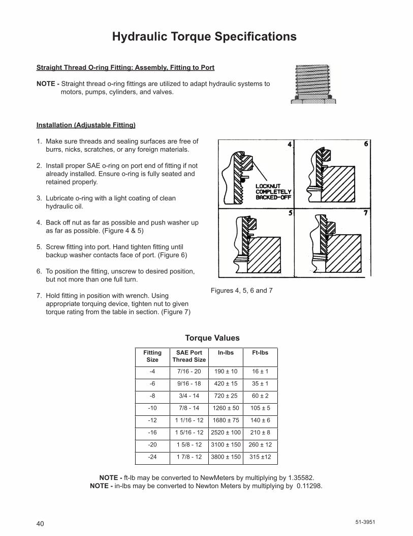
Straight Thread O-ring Fitting: Assembly, Fitting to Port
NOTE - Straightthreado-ringfittingsareutilizedtoadapthydraulicsystemsto motors, pumps, cylinders, and valves.
Installation (Adjustable Fitting)
1. Make sure threads and sealing surfaces are free of burrs, nicks, scratches, or any foreign materials.
2.InstallproperSAEo-ringonportendoffittingifnot already installed. Ensure o-ring is fully seated and retained properly.
3. Lubricate o-ring with a light coating of clean hydraulic oil.
4. Back off nut as far as possible and push washer up as far as possible. (Figure 4 & 5)
5.Screwfittingintoport.Handtightenfittinguntil backup washer contacts face of port. (Figure 6)
6.Topositionthefitting,unscrewtodesiredposition, but not more than one full turn.
7.Holdfittinginpositionwithwrench.Using appropriate torquing device, tighten nut to given torque rating from the table in section. (Figure 7)
Torque Values
Figures 4, 5, 6 and 7
NOTE - ft-lb may be converted to NewMeters by multiplying by 1.35582. NOTE - in-lbs may be converted to Newton Meters by multiplying by 0.11298.
Fitting Size
SAE Port Thread Size
In-lbs Ft-lbs
-4 7/16 - 20 190 ± 10 16 ± 1
-6 9/16 - 18 420 ± 15 35 ± 1
-8 3/4 - 14 720 ± 25 60 ± 2
-10 7/8 - 14 1260 ± 50 105 ± 5
-12 1 1/16 - 12 1680 ± 75 140 ± 6
-16 1 5/16 - 12 2520 ± 100 210 ± 8
-20 1 5/8 - 12 3100 ± 150 260 ± 12
-24 1 7/8 - 12 3800 ± 150 315 ±12

51-3951
41
Limited WarrantyExcept for the Excluded Products as described below, all new products are warranted to be free from defects in material and/or workmanship during the Warranty Period, in accordance with and subject to the terms and conditions of this Limited Warranty.
1. Excluded Products. The following products are excluded from this Limited Warranty:
(a) Any cable, part that engages with the ground (i.e. sprockets), digging chain, bearing, teeth, tamping and/or demolition head, blade cutting edge, pilot bit, auger teeth and broom brush that either constitutes or is part of a product.
(b) Any product, merchandise or component that, in the opinion of Paladin Light Construction1, has been (i)misused;(ii)modifiedinanyunauthorizedmanner;(iii)altered;(iv)damaged;(v)involvedinanaccident;or(vi)repaired using parts not obtained through Paladin Light Construction.
2. Warranty Period. The Limited Warranty is provided only to those defects that occur during the Warranty Period, which is the period that begins on the firsttooccur of: (i) the date of initial purchase by an end-user, (ii) the datetheproductisfirstleasedorrented,or(iii)thedatethatissix(6)monthsafterthedateofshipmentbyPaladinLight Construction as evidenced by the invoiced shipment date (the “Commencement Date”) and ends on the date that is twelve (12) months after the Commencement Date.
3. Terms and Conditions of Limited Warranty. The following terms and conditions apply to the Limited Warranty hereby provided:
(a) Option to Repair or Replace. Paladin Light Construction shall have the option to repair or replace the product.
(b) Timely Repair and Notice. In order to obtain the Limited Warranty, (i) the product must be repaired within thirty (30) days from the date of failure, and (ii) a claim under the warranty must be submitted to Paladin Light Construction in writing within thirty (30) days from the date of repair.
(c) Return of Defective Part or Product. If requested by Paladin Light Construction, the alleged defective part or product shall be shipped to Paladin Light Construction at its manufacturing facility or other location specifiedbyPaladinLightConstruction,withfreightPRE-PAIDbytheclaimant,toallowPaladinLightConstructionto inspect the part or product.
Claims that fail to comply with any of the above terms and conditions shall be denied.
LIMITATIONS AND EXCLUSIONS.
THIS LIMITED WARRANTY IS IN LIEU OF ALL OTHER WARRANTIES, EXPRESS OR IMPLIED, INCLUDING WITHOUT LIMITATION THE WARRANTIES OF MERCHANTABILITY, FITNESS FOR A PARTICULAR PURPOSE AND ANY WARRANTY BASED ON A COURSE OF DEALING OR USAGE OF TRADE.
IN NO EVENT SHALL PALADIN LIGHT CONSTRUCTION BE LIABLE FOR CONSEQUENTIAL OR SPECIAL DAMAGES.
IN NO EVENT SHALL PALADIN LIGHT CONSTRUCTION BE LIABLE FOR ANY LOSS OR CLAIM IN AN AMOUNT IN EXCESS OF THE PURCHASE PRICE, OR, AT THE OPTION OF PALADIN LIGHT CONSTRUCTION, THE REPAIR OR REPLACEMENT, OF THE PARTICULAR PRODUCT ON WHICH ANY CLAIM OF LOSS OR DAMAGE IS BASED. THIS LIMITATION OF LIABILITY APPLIES IRRESPECTIVE OF WHETHER THE CLAIM IS BASED ON BREACH OF CONTRACT, BREACH OF WARRANTY, NEGLIGENCE OR OTHER CAUSE AND WHETHER THE ALLEGED DEFECT IS DISCOVERABLE OR LATENT.
1Attachment Technologies Inc., a subsidiary of Paladin Brands Holding, Inc. (PBHI) is referred to herein as Paladin Light Construction.
February 10, 2010


![MLHPL,MLHRL HP,HR HW,MLHRW B/HR - Hydraulics Inthydraulicsint.com.au/specifications/msHydraulic/SAE3-MOTOR-BRAKE… · Hydraulic Motors Series MLHRL ... ISO code 20/16 ... [31,75]](https://img.pdfslide.net/doc/110x75/5aa177787f8b9a46238bc1b3/mlhplmlhrl-hphr-hwmlhrw-bhr-hydraulics-hydraulic-motors-series-mlhrl-.jpg)