Embed Size (px)
Citation preview

Integrated hydraulic studies to support the masterplan for Mundra Basin Port, Gujarat State, India
HRPP
343
Chesher T.J., McBride M., Shukla M.P. and Smallman J.V.
Reproduced from a paper presented at:The 7th International Conference on Coastal and Port Engineering in Developing Countries (COPEDEC)Dubai, United Arab Emirates24 to 28 February 2008


Integrated hydraulic studies to support the masterplan for Mundra Basin Port, Gujarat State, India 7th International Conference on Coastal and Port Engineering in Developing Countries (COPEDEC)
INTEGRATED HYDRAULIC STUDIES TO SUPPORT THE MASTERPLAN FOR MUNDRA BASIN PORT, GUJARAT STATE, INDIA TJ Chesher1, M McBride1, MP Shukla2 and JV Smallman1 1 HR Wallingford Ltd, OX10 8BA, UK 2 Gujarat Adani Port Ltd Abstract Mundra Port is located on the north side of the Gulf of Kachchh in the NW of India, approximately 100km from the Arabian Sea. The port has been developing over the past 20 years and presently comprises a multi-purpose jetty handling solid bulk, and Mundra International Container Terminal which operates 24 hrs a day, 365 days a year with no tidal restrictions, with vast area for storage and expansion and excellent connections by road and rail links to all the major cargo centres in the North West hinterland and thereby the rest of India. As part of the continuing development of the Port there are proposals to expand the operations by constructing up to five off-shore berths for bulk solids and liquid handling, an enclosed harbour basin with up to 14 alongside berths for container/general cargo/bulk handling, and an offshore berth for cryogenics/chemicals import. Gujarat Adani Port Ltd commissioned HR Wallingford to undertake studies to examine the proposed developments, in respect of navigation and mooring, sedimentation, impact on the existing (hydraulic and sediment) regime, and construction implications (outline breakwater design and sequencing issues). This paper summarises the studies undertaken, highlighting the way in which the often conflicting issues of wave penetration, navigability and sedimentation were resolved in order to arrive at a satisfactory design solution. Particular attention will be given to the issue which arose at this site in relation to the sequencing of the various phases: having established the overall design for the Phase 4 completed layout this had implications for the Phase 1 layout resulting in more complex navigation manoeuvres than would have occurred if designing the Phase 1 layout alone. 1. Introduction In 1998 HR Wallingford studied various development options for Mundra Port based on the Port Master Plan as prepared by Maunsell. Since this time, Mundra Port has been operational and its potential has become clearer, and after examination of the relevant aspects and revised forecasts, Maunsell reviewed the Master Plan, and arrived at a Recommended Development Plan for the period 2005-2010. Figure 1 shows the latest recommended developments, including a basin with substantially modified layout and orientation (compared to the previous Master Plan), two
Liquid Berths and a coal berth spurring off the basin bund, and possibly a cryogenics/chemical Terminal (further to the west of the basin). It is envisaged that this development will be carried out in phases to match the projected growth in traffic and to provide early cash flow as the development proceeds. At each phase it will be essential to determine the operational conditions, in terms of winds, waves, currents and the impact on vessel handling and operations as well as changes to the patterns of sediment movement as it affects dredging and coastal processes.
2008 1 HRPP 343

Integrated hydraulic studies to support the masterplan for Mundra Basin Port, Gujarat State, India 7th International Conference on Coastal and Port Engineering in Developing Countries (COPEDEC)
• Phase 1 – construction of west
breakwater arm, bulk solids and bulk liquid berths
• Phase 2 – construction of off-shore arm of western breakwater and harbour berths
• Phase 3 – completion of the harbour basin
• Phase 4 – construction of the cryogenics/chemical import terminal
The work was commissioned in two stages with Stage 1 comprising the Masterplan developments for Phases 4 and 1: Phase 4 to ensure that the overall Masterplan design will be effective, and Phase 1 to cover the initial phase of the development. This paper covers the studies for Stage 1.
Figure 1 Proposed Development of Mundra Basin Port Initial consideration by HR Wallingford raised concern that the basin would not be large enough, and the entrance would not be wide enough to allow safe passage of ships into the port whilst ensuring safe stopping distances. Accordingly, a revised layout was devised which comprised a larger basin with bunds extending out to beyond the -5mCD contour giving a stopping distance of order 1km, and with a wider entrance. Following this initial consideration, it was agreed that the methodology for the project should follow the following process:
1. Confirmation of the design basis; 2. Tidal flow modelling for the two
layouts of the Phase 4 basin to provide information to be used as input to navigation studies;
3. Navigation simulation studies to confirm the basin layout and thereafter to check entrance and berthing manoeuvres;
4. Finalise the flow modelling accounting for any modifications to the layout;
5. Wave propagation and wave disturbance modelling, taking into
2008 2 HRPP 343

Integrated hydraulic studies to support the masterplan for Mundra Basin Port, Gujarat State, India 7th International Conference on Coastal and Port Engineering in Developing Countries (COPEDEC)
consideration the design basis in respect of downtime in the basin;
6. Ship mooring analysis; 7. Channel and basin sedimentation
studies; 8. Engineering design support to
investigate specific issues associated with trestles, berths, bunds and other land-based issues.
2. Design basis A key issue in respect of the design basis was the requirement that there should be access to the Port in all conditions and all states of the tide. On this basis it was agreed that the Port basin be designed in order to allow safe access and hence an alternative basin arrangement was devised comprising wider entrance and larger basin. It was acknowledged that this more open design would give rise to greater penetration of wave energy and potential consequential downtime issues at some of the interior berths, but this was considered preferential to limiting the time-window of access for vessels to periods of slack water. It was anticipated that entry and exit manoeuvres will be difficult for a 24h basin access for large vessels. There are two main methods for entering the basin at high current flow: The vessel approaches across the tide, adopting a drift angle to ensure it tracks directly across the tide and hence through the entrance. This method requires the ship to go at least one and a half to two times the speed of the tidal flow. As the tidal stream comes off the bow, the ship will turn to being more parallel with the tidal stream, and so will tend to go along the line of the basin.
The vessel approaches slowly against the tide, and turn into the basin, allowing the tidal flow to take it into the basin. This requires a high level of control to be exercised over the ship. It is anticipated that the terminal should be designed to handle the typical vessels presented in Table 1 below. Table 1 Design vessels
Type LOA Max draught Beam
ULCC 367 15.0 42.8 Bulk Carrier 250 14.5 38.0 Feeder vessel 290 13.0 32.4
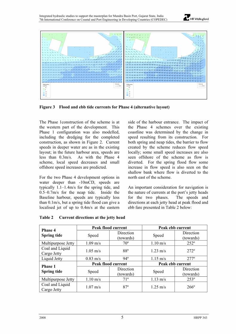
Note that most feeders are much smaller than the one presented in the above table. 3. Tidal currents and waves HR Wallingford has undertaken a number of projects at Mundra, and has developed a well-calibrated TELEMAC-2D flow model of the region which was used in the present study. Given the concern over navigability of the basin (Phase 4), the proposed scheme and alternative (larger, wider-entranced) scheme were included in the model. The two development options were modelled for input to the navigation simulation, in order to inform selection of the best scheme. Spring and neap tides were modelled for the layouts shown in Figure 2 below. Example flood and ebb tide currents for Phase 4 are shown in Figure 3 below.
2008 3 HRPP 343

Integrated hydraulic studies to support the masterplan for Mundra Basin Port, Gujarat State, India 7th International Conference on Coastal and Port Engineering in Developing Countries (COPEDEC)
EXISTING
ALTERNATIVE SCHEME, phase 4
BASELINE SCHEME, phase 4
BASELINE SCHEME, phase 1
Bathymetry(mCD)
-30
-24
-22
-20
-18
-16
-14
-12
-10
-8
-6
-4
-2
0
2
4
10
MPJ
coal and liquidcargo jetty
liquidjetty
-17mCD
Figure 2 Layouts simulated in the flow model
2008 4 HRPP 343
Integrated hydraulic studies to support the masterplan for Mundra Basin Port, Gujarat State, India 7th International Conference on Coastal and Port Engineering in Developing Countries (COPEDEC)
2008 5 HRPP 343
Bathymetry(mCD)
-30
-20
-10
0
10
Velocity1m/s
Bathymetry(mCD)
-30
-20
-10
0
10
Velocity1m/s
Figure 3 Flood and ebb tide currents for Phase 4 (alternative layout) The Phase 1construction of the scheme is at the western part of the development. This Phase 1 configuration was also modelled, including the dredging for the completed construction, as shown in Figure 2. Current speeds in deeper water are as in the existing layout; in the future harbour area, speeds are less than 0.3m/s. As with the Phase 4 scheme, local speed decreases and small offshore speed increases are predicted. For the two Phase 4 development options in water deeper than -10mCD, speeds are typically 1.1–1.4m/s for the spring tide, and 0.5–0.7m/s for the neap tide. Inside the Baseline harbour, speeds are typically less than 0.1m/s, but a spring tide flood can give a localised jet of up to 0.4m/s at the eastern
side of the harbour entrance. The impact of the Phase 4 schemes over the existing coastline was determined by the change in speed resulting from its construction. For both spring and neap tides, the barrier to flow created by the scheme reduces flow speed locally; some small speed increases are also seen offshore of the scheme as flow is diverted. For the spring flood flow some increase in flow speed is also seen on the shallow bank where flow is diverted to the north east of the scheme. An important consideration for navigation is the nature of currents at the port’s jetty heads for the two phases. The speeds and directions at each jetty head at peak flood and ebb fare presented in Table 2 below:
Table 2 Current directions at the jetty head
Peak flood current Peak ebb current Phase 4 Spring tide Speed Direction
(towards) Speed Direction (towards)
Multipurpose Jetty 1.09 m/s 70º 1.10 m/s 252º Coal and Liquid Cargo Jetty 1.05 m/s 88º 1.23 m/s 272º
Liquid Jetty 0.83 m/s 94º 1.15 m/s 277º Peak flood current Peak ebb current Phase 1
Spring tide Speed Direction (towards) Speed Direction
(towards) Multipurpose Jetty 1.10 m/s 71º 1.13 m/s 253º Coal and Liquid Cargo Jetty 1.07 m/s 87º 1.25 m/s 266º

Integrated hydraulic studies to support the masterplan for Mundra Basin Port, Gujarat State, India 7th International Conference on Coastal and Port Engineering in Developing Countries (COPEDEC)
Wave conditions at Mundra are a combination of swell waves incident from the Arabian Sea and wind waves generated locally across the Gulf of Kachchh. Two sets of wave conditions were studied: for the purposes of downtime estimation, relatively frequent conditions were derived from the wind climate and observed offshore wave climate. For the purposes of design, wave conditions were derived from available cyclone records. Extreme swell wave and wind wave conditions were derived in a previous study
and transformed inshore to a point in the area of the development at a depth of -15mCD. Swell waves were derived from the UK Meteorological Office Global wave model, transformed into the Gulf of Kachchh with the HR Wallingford TELURAY model. Locally generated wind waves were derived from extreme winds using the HR Wallingford JONSEY model. Four conditions previously tested were chosen as representative of the main wave sources and direction sectors. The conditions tested are shown in the table below.
Table 3 Wave conditions for tranquility and downtime assessment Return Period
Type of wave Offshore direction
Inshore Hs Inshore Tp Inshore direction
(years) (°N) (m) (s) (°N) 1 Swell 250 0.9 12.5 219 1 Windwave 230 1.2 5.1 231 5 Windwave 140 1.2 5.1 231 5 Windwave 190 0.8 3.6 194
After the conditions above were derived, a dataset of observations was been made available including observations of wave height in the area for 4 weeks during the south west monsoons of 1993 and 1994 (Reference 1) and this data set was used to verify the UKMO model data. Wave disturbance modelling was carried out using the ARTEMIS wave disturbance model which was developed by the National Hydraulics Laboratory (Laboratoire National d’Hydraulique – LNH) of the Research and Development Division of the French Electricity Board, Electricité de France (EDF-DER). ARTEMIS is a linear finite element model, which is used to calculate wave heights in an area of interest corresponding to a given incident wave condition. ARTEMIS includes the effects of depth refraction and shoaling, diffraction due to the seabed and around surface piercing structures and complete or partial reflections from harbour boundaries. The energy dissipation processes of wave breaking and
seabed friction are also included in the model. The ARTEMIS wave disturbance model was set up to model harbour layouts corresponding to Phase 1 and Phase 4 of the proposed development. The incident wave boundary follows the approximate line of the -17mCD contour, allowing full representation of the dredged entrance in Phase 4. For Phase 4, separate model meshes were created for the longer (Tp > 4s) and shorter waves (Tp < 4s), with coarser and finer mesh resolution respectively. The shorter period waves are incident from the south east, and in Phase 1 pass no significant barrier before reaching the quay, hence the transformation of these waves was directly. All conditions were run with a water level of +5.8mCD (MHWS). The reflection properties of the boundaries of the proposed harbour were represented in the ARTEMIS model by assigning an appropriate reflection coefficient (Cr) to each of the boundary types. These reflection
2008 6 HRPP 343

Integrated hydraulic studies to support the masterplan for Mundra Basin Port, Gujarat State, India 7th International Conference on Coastal and Port Engineering in Developing Countries (COPEDEC)
coefficients were calculated using a method developed at HR Wallingford, (Reference 2), which takes into account the type of construction and slope of the boundary as well as the incident wave conditions. A reflection coefficient of Cr = 1.0 indicates that all the incident wave energy will be reflected, while a lower reflection coefficient indicates that some wave energy will be dissipated. Vertical walls with or without sheet piles, and caissons were assigned a reflection coefficient of Cr = 0.95. The outer faces of the reclamations and breakwaters, and the inner face of the eastern breakwater, were taken to be constructed with a rock armour slope of 1:2 and assigned a reflection coefficient of Cr = 0.6 and Cr = 0.5 for the long and short period waves, respectively.
The shorter period waves are incident from the south east, and in Phase 1 pass no significant barrier before reaching the quay. Any refraction due to the shoaling bathymetry of the undredged bar that will host the western breakwater in Phase 4 is reversed as the bathymetry deepens into the basin. The bathymetry is sufficiently deep that breaking of the incident south-easterly waves would be restricted to a small area of the bar and low water only, providing negligible shelter to the quays. Hence the transformation of these waves can be calculated directly. The wave energy at the quay is made up of incident and reflected components, which were added on an energy basis. Example patterns of wave disturbance are shown in Figure 4 below.
Figure 4 Example wave disturbance pattern using ARTEMIS At Phase 1, while the south-westerly waves are directly incident, the berths are well sheltered as a relatively small proportion of the wave energy diffracts northward. There are significant reflections within the basin at Phase 4, with the greatest wave heights occurring in the northeast corner, and standing waves developing also in the northwest and southwest corners. Significant
wave heights around the proposed harbour corresponding to the four incident conditions under consideration are given in the tables below. Locations A to K correspond to sections of quay, location L is representative of the mid-basin wave height, and location M corresponds to the coal and liquid cargo jetties.
2008 7 HRPP 343

Integrated hydraulic studies to support the masterplan for Mundra Basin Port, Gujarat State, India 7th International Conference on Coastal and Port Engineering in Developing Countries (COPEDEC)
Table 4 Significant wave heights at locations around the proposed harbour - Phase 1
Wave condition
1/1year swell from 250N
1/1year windwave from 230N
1/5year windwave from 140N
1/5year windwave from 190N
Hs (m)
Tp (s)
Dir (°N)
Hs (m)
Tp (s)
Dir(°N)
Hs (m)
Tp (s)
Dir (°N)
Hs (m)
Tp (s)
Dir(°N)
Inshore wave conditions at -17mCD 0.9 12.5 219 1.2 5.1 231 0.7 3.4 138 0.8 3.6 194
Location C 0.5 0.3 1.0 1.1 Location D 0.3 0.2 1.0 1.1 Location L 0.9 1.0 0.7 0.8 Location M 1.0 1.2 0.7 0.8
2008 8 HRPP 343

Integrated hydraulic studies to support the masterplan for Mundra Basin Port, Gujarat State, India 7th International Conference on Coastal and Port Engineering in Developing Countries (COPEDEC)
2008 9 HRPP 343
Table 5 Significant wave heights (m) at locations around the proposed harbour – Phase 4
Wave condition
1/1year swell from 250N
1/1year windwave from
230N
1/5year windwave from
140N
1/5year windwave from
190N Hs (m)
Tp (s)
Dir (°N)
Hs(m)
Tp (s)
Dir (°N)
Hs(m)
Tp (s)
Dir (°N)
Hs (m)
Tp (s)
Dir (°N)
Inshore wave conditions at -17mCD 0.9 12.5 219 1.2 5.1 231 0.7 3.4 138 0.8 3.6 194 Location A 0.7 0.4 0.4 0.5 Location B 0.8 0.5 0.5 0.4 Location C 0.7 0.5 0.5 0.4 Location D 0.6 0.5 0.3 0.4 Location E 0.6 0.5 0.6 0.4 Location F 0.6 0.6 0.4 0.3 Location G 0.7 0.6 0.4 0.3 Location H 0.8 0.9 0.3 0.5 Location I 1.4 1.2 0.3 0.6 Location J 1.2 0.6 0.2 0.3 Location K 1.2 0.9 0.2 0.6 Location L 0.5 0.7 0.5 0.4 Location M 1.1 1.3 0.7 0.9

Integrated hydraulic studies to support the masterplan for Mundra Basin Port, Gujarat State, India 7th International Conference on Coastal and Port Engineering in Developing Countries (COPEDEC)
The potential resonance of the proposed Phase 4 basin was also investigated by running the ARTEMIS wave disturbance model in period scanning mode. The amplification of south westerly incident waves was assessed for periods between 5 and 75 seconds. No significant resonance was observed with only mild peaks of response occurring at wave periods of 23s and 68-70s. 4. Navigation and ship mooring studies This section describes a real time navigation simulation study undertaken by HR Wallingford to assess navigation at the proposed Port basin development. It builds directly on the initial flow modelling studies and the previous navigation studies HR Wallingford have undertaken at Mundra. The outcomes from the navigation assessment were used to establish the design of the port layouts considered in subsequent flow modelling and wave prediction studies. For this study, real time navigation simulation techniques were used to: • Establish the feasibility of manoeuvring
the design vessels at the proposed Port Basin development in a range of adverse conditions
• Optimise, from a navigation perspective, the design of the Port Basin development. Ship manoeuvres with three port layouts were simulated – Phase 1 and two alternative layouts for Phase 4 (Base Case and Alternative Case)
• Assess the safe operating limits, and associated tug requirements
• Determine the footprint of the dredged area required for safe manoeuvring (Phase 1 and Phase 4).
4.1 The HR Wallingford Ship Simulator The Ship Simulator at HR Wallingford is specifically designed for port design and ship operations applications. It has been used successfully in over 200 studies world-wide and has proved to be a reliable, flexible and cost-effective design and evaluation tool that
can be used for optimising harbour layouts, establishing operational strategy and training in safe manoeuvring procedures. The aim of the simulator is to present to pilots and/or mariners the visual and other information, such as the coastline and port infrastructure, which they would experience in bringing a ship into a port. In this way the essential features of the human input can be retained. Ship manoeuvring models of the design vessels will be produced so that the pilot receives realistic positioning cues during manoeuvres. The vessels can then be operated in a realistic manner. In the navigation simulation runs, the behaviour and performance of ships, in terms of response to any helm, engine or tug control, and the local wind, wave and current conditions, is governed by a mathematical ship manoeuvring model. The mathematical model of the ship must behave in such a way that the position, velocity, swept path and heading of the simulated ship are always representative of real ship behaviour. For this study, ship manoeuvring models of these ships were retrieved from HR Wallingford’s library of ship manoeuvring models. These ship models included motions in three degrees of freedom (3DOF), representing surge, sway and yaw motions (i.e. those directly affecting horizontal motions, and therefore navigation). However, the models also include determination of vessel squat and shallow water behaviour to ensure representative manoeuvring behaviour in relatively shallow water, where appropriate. The main focus for this study was the Phase 4 layout for the proposed Basin development. Initially two versions of the Phase 4 layout were simulated: • Base Case design (see Figure 2) which
features a “small” basin, rubble mound breakwaters, offset entrance with 200m wide full depth channel through entrance (approximately 425m between the breakwater tips)
2008 10 HRPP 343

Integrated hydraulic studies to support the masterplan for Mundra Basin Port, Gujarat State, India 7th International Conference on Coastal and Port Engineering in Developing Countries (COPEDEC)
2008 11 HRPP 343
• Alternative Case design which features a “larger” basin, rubble mound breakwaters, offset entrance with 400m wide full depth channel through entrance (approximately 585m between the breakwater tips). This alternative basin design was proposed by HR Wallingford in response to concerns regarding the navigability of the Base Case design.
During the simulation runs it became clear that, from a navigation perspective, the basin design could be improved. On this basis, modified versions of the Base Case layout were used to assess increased entrance widths. The flow data for the simulations were taken from the TELEMAC computational flow models (see Section 2). The flow patterns and height of tide (HoT) associated with four tidal snapshots from a spring tide (range 5.4m) were set up in the simulator for all three initial development layouts. The current speed in each cell could be scaled to achieve the desired current speed at a particular location. In particular, on the advice of the local mariners, the flows were scaled up to achieve current speeds of 3.1 knots approximately 500m south of the existing multi-purpose jetty, to represent the peak ebb and flood current speeds observed at some times of the year. Up to four tugs were available to assist the manoeuvring vessels. Each of the tugs was controlled independently in response to the Pilot’s orders. The maximum tug force deliverable by the tugs varied with vessel water speed, assist mode and the wave conditions. Realistic response times and performance limitations were used for the various tug operations.
For the purposes of this study it was assumed that all the tugs had twin ASD (azimuth stern drive) propulsion fitted with standard fittings, and static (conventional) winches. During the runs, the wave effectiveness of the tugs was reduced according to pre-determined tug effectiveness curves. A total of 34 runs were undertaken for this study. The run scenarios focused on standard arrival manoeuvres at the proposed development in a range of environmental conditions, along with some departures and scenarios where the vessel was simulated as suffering some form of credible equipment failure. To make best use of the time available the simulations focussed on key sections of the manoeuvres, e.g. the approach to the basin entrance. At the start of each run, the ship’s position, heading, and forward and transverse speeds were estimated by the Pilot and Simulator Operator, based on the type of manoeuvre, the wind and current conditions, and experience. Immediately after completion of the simulation, each run was graded by the Simulation Team as Successful, Marginal or Fail. The results from each navigation simulation run are available in the form of plots of the vessel tracks, and graphs of key data parameters recorded during the run. Video footage of some of the navigation simulation runs was also recorded from the Simulator Bridge. The figure below shows an example vessel track for one of the simulations.

Integrated hydraulic studies to support the masterplan for Mundra Basin Port, Gujarat State, India 7th International Conference on Coastal and Port Engineering in Developing Countries (COPEDEC)
Figure 5 Example ship simulator track plot
2008 12 HRPP 343

Integrated hydraulic studies to support the masterplan for Mundra Basin Port, Gujarat State, India 7th International Conference on Coastal and Port Engineering in Developing Countries (COPEDEC)
4.2 Conclusions and recommendations from the navigation study • The 200m wide navigable entrance,
initially proposed with the Phase 4 Base Case Basin layout design, was considered to be too narrow for the design container vessel to navigate safely, even in benign conditions. However, it is judged that the width of the Base Case Basin it is adequate, but there are limited options for actions to resolve any emergency or failure situation acceptably on entry.
• The 400m wide navigable entrance to the
Phase 4 Alternative Case Basin is considered to be navigationally feasible for the design container vessel at all states of the tide, and with monsoon winds of 30 to 38 knots from the SW, provided suitable manoeuvring strategies are used and adequate tug procedures are adopted. The navigation situation would, however, be enhanced by reducing the stagger between the breakwaters.
• The Phase 4 Base Case basin with a
navigable entrance width of 400m is considered to be navigationally feasible for the design vessels within the design operating limits, provided suitable manoeuvring strategies are used and adequate tug procedures are adopted. From a navigation perspective, it would be beneficial to move the entrance west, from its proposed offset position, to the middle of the basin. This would allow space for vessels to turn to starboard as well as to port inside the basin entrance, which would improve safety margins. On the basis of the wave disturbance modelling, however, where it was concluded that the NE berths would experience high wave energy, it is recommended that the basin entrance remain toward the eastern side of the basin thereby minimising the berth length affected by high wave action.
• On the basis of these studies, an
optimised Basin layout was devised, which was based on the Base case layout,
but with increased entrance width to 400m.
• If rubble mound breakwaters are used for
the Basin development, the extent of the full depth (navigable) channel through the entrance should be marked (with, for example, two buoys). If the construction of the breakwaters allows for full depth throughout the entrance gap (e.g. vertical-sided breakwater roundheads) the entrance gap will appear narrower on approach, but the Pilots can be confident of the extent of the fairway.
• It was demonstrated that at least four
tugs, each capable of delivering 70t of thrust will be required to manoeuvre the design container vessel safely during the SW monsoon period. This is due to the high wind loading associated with beam, and near-beam winds for this size and class of ship. Both the design container vessel and design bulker required two active tug escorts (i.e. tugs made fast on lines, and ready to assist immediately) on the bow and stern centre leads during the approach and entry to the basin.
• It is judged to be feasible for the design
container vessel to operate from the Phase 1 berth, although in adverse conditions the arrival manoeuvres in particular will be tug intensive. The vessel essentially used the full area of the future basin during the manoeuvres and on this basis it is recommended that the entrance area remains as tested in the Phase 4 layout (i.e. although the tests of the Phase 4 simulations concluded that it was preferable to relocate the entrance further to the west (to allow greater manoeuvring space within the basin to the east), the implications in terms of navigation in Phase 1 preclude this).
• The berthing line of the proposed Coal
and Liquid Cargo Jetty should be parallel to the natural seabed contours (and therefore the flood and ebb tidal flows) at approximately the natural -15mCD seabed contour. Overall, the navigation situation at the proposed Coal and Liquid
2008 13 HRPP 343

Integrated hydraulic studies to support the masterplan for Mundra Basin Port, Gujarat State, India 7th International Conference on Coastal and Port Engineering in Developing Countries (COPEDEC)
2008 14 HRPP 343
Cargo Jetty is expected to be similar to that at the existing Multi-purpose Jetty.
• Throughout the simulations, the vessels
manoeuvring in the approaches to the proposed Basin were able to maintain acceptable clearances to both the existing Multi-purpose Jetty and the proposed Coal and Liquid Jetty. The presence of these structures did, however, constrain the line of approach to the basin entrance in some combinations of wind and current conditions.
• It was recommended that the Pilots, Tug
Skippers and Tug Crews should all complete appropriate training and integrated familiarisation exercises for manoeuvring vessels with the proposed developments in place. Furthermore, it will also be important to develop, and practice, strategies for dealing with a range of failure events such as ship engine and steering failures, and tug line failures.
4.3 Ship mooring analysis Tests were carried out using computational modelling to evaluate the viability of proposed berths for moored ships subject to wave and current action. Four design ships were selected to be representative of the vessels expected to use the facilities, and were modelled moored at the appropriate berths in wave and current conditions predicted as described above. The magnitudes of the vessels’ movements, and mooring loads in these conditions were then compared with established criteria for safe cargo handling and survivability at berth to give estimates of the berths’ operational wave and current envelopes - and thus an indication of likely berth downtime. Tests were carried out using HR Wallingford’s UNDERKEEL and SHIPMOOR computational models. The testing procedure in outline is: UNDERKEEL is used to calculate wave forcing and damping coefficients in the frequency domain. Included in the calculations are long-period second-order force components, which have been shown to
be significant for driving large amplitude long period movements of moored ships. From the frequency coefficients, computed wave forcing sequences can be synthesised acting on the ship for any desired incident wave condition. These forcing sequences are then input to SHIPMOOR, which calculates the resulting movements of the ship, with the corresponding forces in mooring lines and fenders. In general, wind action was not expected to be a significant factor affecting moored ships at the proposed berths. In addition, the alignment of most berths is such that an onshore wind, which would be expected generally to coincide with most significant wave activity, would also be on-berth and thus generally inhibit vessel motion and cause a reduction in mooring line loads – although possibly with raised fender loads. Three design ships were selected for testing to be representative of ships expected to visit the harbour. The ships were: • A 295m LOA container vessel, based on
the ‘Shanghai Express’. This ship was modelled moored only at berths within the basin.
• A 150,000dwt Capesize bulk carrier, which was modelled moored both at berths within the basin and at the exterior Coal and Liquid Cargo Jetty.
• A 150,000m3, spherical containment LNG carrier. This was modelled moored only at the, external, LNG jetty.
The principal dimensions of the three ships are given below, Table 6. All were tested in both fully laden and in ballast conditions. Berth arrangements for the berths inside the basin and on the Coal and Liquid Cargo Jetty were assumed to be similar, with bollards and fenders at 19.5m intervals. This is a typical spacing for container and bulk carrier berths currently planned and being constructed, and it resulted in the mooring plans shown below, Figures 6,7. For the LNG berth, a typical current island berth design was selected, which gave the mooring arrangement shown, Figure 8.

Integrated hydraulic studies to support the masterplan for Mundra Basin Port, Gujarat State, India 7th International Conference on Coastal and Port Engineering in Developing Countries (COPEDEC)
Table 6 Design ships, principal characteristics Ship Shanghai Express Capesize bulker 150k m3 LNG
(spherical) Length, overall 294m 270m 283m Length, between perpend’s
281.5m 260m 270m
Beam 32.3m 43m 43.4m Draught (loaded) 12m 17.7m 12m Draught (ballast) 9.5m 10m 9m Displacement (loaded)
75,600t 161,500t 108,700t
Displacement (ballast)
57,700t 87,300t 78,100t
Depth 22m 25m 26m Windage lateral 7044m2 2355m2 8200m2 Windage frontal 1057m2 735m2 1800m2 Mooring lines, no. 14 14 18 Mooring lines, type 36mm, steel wire 36mm, steel wire 44mm, synthetic Mooring lines, MBL 89t 89t 138t Tails, length 11m 11m 11m Tails, type 96mm nylon 96mm nylon 64mm, synthetic Tails, MBL 129t 129t 188t
Figure 6 Shanghai Express mooring arrangement
2008 15 HRPP 343

Integrated hydraulic studies to support the masterplan for Mundra Basin Port, Gujarat State, India 7th International Conference on Coastal and Port Engineering in Developing Countries (COPEDEC)
2008 16 HRPP 343
Figure 7 Bulk carrier mooring arrangement
Figure 8 LNG carrier mooring arrangement
Ships were moored starboard-side to the berth in all cases, as shown in the figures. At the external berths, this arrangement resulted in the ships mooring with bows directed out to sea, which is the normally preferred orientation at most sites. Within the basin, the choice is arbitrary, but not significant: given the assumed uniform directional distribution of wave energy, vessel movements and mooring forces will be similar whichever the orientation of the mooring.
Fenders on the berths within the basin and at the Coal and Liquid Cargo Jetty were assumed for modelling purposes to have linear load-compression characteristics, with a rate of 1000tf per metre compression. On the LNG berth, Fentek SCN 1800(E3.1) type fenders were assumed and simulated. Ship motions were tracked and the extremes recorded for each test in each of the six modes of motion:
Mooring line characteristics for the three design ships are listed in Table 6. All ships were simulated moored with 10t pre-tension in mooring lines.
• Surge – fore-and-aft movement, positive being forward
• Sway – lateral movement, positive being to port

Integrated hydraulic studies to support the masterplan for Mundra Basin Port, Gujarat State, India 7th International Conference on Coastal and Port Engineering in Developing Countries (COPEDEC)
• Heave – vertical movement, positive being upward
• Roll – rotation about the longitudinal axis, positive being port side upward
• Pitch – rotation about the lateral axis, positive being bow down
• Yaw – rotation about the vertical axis, positive being bow to port
Thoresen (Reference 3) gives criteria for the maximum acceptable ship motions for safe operations, Table 7. Except for sway, these are ‘peak-to-peak’ values: sway values are maximum acceptable distances moved away from the berthing line:
Table 7 Recommended motion criteria for safe working conditions Surge (m) Sway (m) Heave (m) Roll (deg) Pitch (deg) Yaw (deg) Container ship, 100% efficiency
1.0 0.6 0.8 3 1 1
Container ship, 50% efficiency
2.0 1.2 1.2 6 2 1.5
Bulk carrier, crane unloading
2.0 1.0 1.0 6 2 2
LNG carrier
2.0 2.0 - 2 2 2
In addition, it is widely accepted that safe working loads in mooring lines should not exceed 55% of MBL, to avoid damaging and weakening the lines. Loads in fenders similarly must not exceed their rated capacity, which is 420t for the SCN1800((E3.1) type simulated here. These considerations implied the following limits on acceptable mooring loads: Shanghai Express mooring lines: 49t Bulk carrier mooring lines: 49t LNG carrier mooring lines: 76t Fenders: 420t The maximum loads in mooring lines and fenders were also recorded. This analysis resulted in a large dataset of conditions of vessel movement for comparison with the acceptable criteria. Two levels of acceptability were given for container ship motions: showing motions that exceed the threshold for handling cargo 100% efficiently and those exceeding the (higher) criterion for 50% efficiency.
Locally wind-generated waves do not cause disturbance of any of the test ships in any test case sufficient to disrupt cargo handling. Berth downtime due to locally generated wind waves is consequently predicted to be negligible. The generally longer period, distantly generated waves however can cause considerably greater disturbances of all the moored ships, and berth downtime is forecast due to distantly generated wave action. Wind and current effects on moored ships are relatively insignificant and do not contribute significantly to berth downtime at this site. 4.4 Berth unavailability/downtime estimate based on mooring analysis An initial downtime estimate (based on wave thresholds) was refined on the basis of the ship mooring studies. The thresholds of maximum operable significant wave height were refined taking into account the loading state of the vessel, and variation of direction of incident waves between berths (Table 8).
2008 17 HRPP 343

Integrated hydraulic studies to support the masterplan for Mundra Basin Port, Gujarat State, India 7th International Conference on Coastal and Port Engineering in Developing Countries (COPEDEC)
Estimates of berth unavailability based on these thresholds are given in Table 9, and these confirmed earlier findings, as expected,
that the berths on the eastern side of the basin are subject to higher downtime.
Table 8 Downtime thresholds for various classes of vessel based on mooring analysis, in
terms of significant wave height (Hs, m)
Class of vessel Location Loading state Threshold in Hs (m) for waves of peak
period 6-10s
Threshold in Hs (m) for waves of peak
period 10-15s Exterior Laden 1.50 1.45 LNG Ballast 1.35 1.50
Laden 0.65 0.45 Phase 1 Ballast 0.65 0.45 Laden 1.50 1.15
Shanghai Express (Containers) Basin
(Phase 4) Ballast 1.50 0.65 Laden 1.15 0.65 Phase 1 Ballast 1.05 1.05 Laden 1.35 0.35 Basin
(Phase 4) Ballast 0.95 0.45 Laden 1.05 0.45
Bulkers
Exterior Ballast 0.65 0.45 Table 9 Estimates of percentage of high waters when downtime due to waves would occur, based on mooring analysis
Phase 1 Phase 4 Location** Class of vessel
Loading State Thresholds
(m Hs) Total sea (swell)
downtime Thresholds (m Hs) Total sea (swell)
downtime
Laden - - >1.5(1.15) 2.0% A Shanghai Express (Container)
Ballast - - >1.5(0.65) 2.0%
Laden - - >1.5(1.15) 3.0% B Shanghai Express (Container)
Ballast - - >1.5(0.65) 3.0%
Laden 0.65(0.45) <0.1% >1.5(1.15) 2.0% C Shanghai Express (Container)
Ballast 0.65(0.45) <0.1% >1.5(0.65) 2.0%
Laden 0.65(0.45) <0.1% >1.5(1.15) 1.2% D Shanghai Express (Container)
Ballast 0.65(0.45) <0.1% >1.5(0.65) 1.2%
Laden - - >1.5(1.15) 1.2% E Shanghai Express (Container)
Ballast - - >1.5(0.65) 1.2%
Laden - - >1.5(1.15) 1.2% F Shanghai Express (Container)
Ballast - - >1.5(0.65) 1.2%
Laden - - >1.5(1.15) 2.0% G Shanghai Express (Container)
Ballast - - >1.5(0.65) 2.0%
2008 18 HRPP 343

Integrated hydraulic studies to support the masterplan for Mundra Basin Port, Gujarat State, India 7th International Conference on Coastal and Port Engineering in Developing Countries (COPEDEC)
Laden - - 1.35(0.35) 3.0% H Bulker Ballast - - 0.95(0.45) 6.5% Laden - - 1.35(0.35) 12%* I Bulker Ballast - - 0.95(0.45) 20%* Laden - - 1.35(0.35) 8.7% J Bulker Ballast - - 0.95(0.45) 6.0% Laden - - 1.35(0.35) 8.8% K Bulker Ballast - - 0.95(0.45) 12%* Laden 1.05(0.45) 10.0% 1.05(0.45) 13%* M Bulker/
Liquid tanker
Ballast 0.65(0.45) 6.0% 0.65(0.45) 7.2%
Laden >1.5(1.45) <0.1% >1.5(1.45) <0.1% LNG Jetty LNG Ballast 1.35(>1.5) 1.4% 1.35(>1.5) 1.4%
* Values quoted above 10% are extrapolated, and may be underestimates. ** See Table 5 for locations 5. Sedimentation and coastal impact Following the tidal flow modelling and navigation simulation studies which are described in the earlier sections, sediment transport modelling was carried out for the two confirmed phase layouts of the development in order to assess the potential sedimentation within the new Port area, and also to identify potential impacts in terms of coastal erosion. Simulations were carried out using the HR Wallingford model, SUBIEF which is a suspended sediment transport model. The simulations performed covered the range of sediments at the site ranging from silts to sand, as in the earlier study, and covering the range of suspended sediment concentration and sediment settling velocity. For the simulations of silt transport tests were carried out with settling velocities of 0.2mm/s, 1.5mm/s and with corresponding offshore suspended sediment concentrations of 400mg/l and 800mg/l respectively for the spring tide scenarios. Under neap tide conditions the offshore suspended sediment concentration levels were halved. For the sand transport modelling the offshore concentration was set to 100mg/l and the settling velocity was specified as 5mm/s. This approach is consistent with the previous modelling undertaken by HR Wallingford at this site and confirmed valid for the
sedimentation at the existing Container terminal. Simulations were performed for the Phase 4 (optimised) layout determined from the flow modelling and navigation simulation studies, and for the Phase 1 layout. In Phase 4 the basin and short approach channel was dredged to -17mCD, and whereas in Phase 1 it would not be necessary to dredge this entire amount, the simulations for Phase 1 were also carried out using the same dredged footprint as in Phase 4. This decision was based on the fact that the vessel swept path from the navigation simulations for Phase 1 indicated that all of the western areas of the “basin” would be required for manoeuvring and also a proportion of the eastern areas, and also because all of the area may be dredged due to land fill requirements. On this basis the estimates of sedimentation in the Phase 1 development may be considered as conservative. A comparison of the model geometry files for existing conditions and for the Phase 4 layout indicated that the (capital) volume of material removed from the dredging footprint was of the order of 30Mm3. For each simulation SUBIEF was run for spring and neap tide conditions and the results were presented in terms of the peak suspended sediment concentration (over the period simulated) and the net deposition
2008 19 HRPP 343

Integrated hydraulic studies to support the masterplan for Mundra Basin Port, Gujarat State, India 7th International Conference on Coastal and Port Engineering in Developing Countries (COPEDEC)
occurring over the tide. The depth of sediment presented was calculated from the mass of sedimentation and assuming a dry density of 500kg/m3 for the silt and 1300kg/m3 for the sand. 5.1 Phase 4 basin sedimentation Figure 9 shows example pattern of peak concentration and net deposition over the tide for the case of high levels of offshore concentration (and settling velocity), for spring tide conditions. The results suggested that the entrance area and eastern part of the basin are likely to experience higher levels of sedimentation than the berths in the western part of the basin, although it should be borne in mind that both ship motion and wave action (especially in the eastern portion of the
basin) will tend to inhibit the settling so that the infill pattern may be more uniform. Clearly, spring tide patterns of sedimentation are significantly higher than under neap tides. The annual deposition in the basin and channel approaches was calculated from the various results, as summarised in Table 10 below. This information confirms that the infill due to sand is a relatively small contribution when compared to that due to silt, and also that the volume of siltation arising from the simulations using a lower offshore concentration and settling velocity of 0.2mm/s gives rise to a worst case infill (total) of order 830,000m3/year.
Table 10 Phase 4 basin sedimentation prediction
Sediment type Infill contribution spring tides m3/year
Infill contribution neap tides m3/year
Annual infill m3/year
Silt (low offshore concentration low settling velocity) 661,500 164,500 826,000
Silt (high offshore concentration high settling velocity) 289,500 24,000 313,500
Fine sand 7,000 0 7000 Total infill (worst case sand and silt total) 833,000
5.2 Phase 1 sedimentation Simulations were repeated for the Phase 1 basin scenario. Figure 10 shows example pattern of peak concentration and net deposition over the tide for the case of high levels of offshore concentration (and settling velocity), for spring tide conditions. Note that as described above, these simulations were carried out assuming the same dredged footprint as for Phase 4. These results suggest that the dredged area will experience relatively high levels of infill which is mainly a consequence of the exposed nature of the dredged zone, and the extent (depth) of dredging. As predicted for the Phase 4 basin, the infill under spring tide conditions is much higher than that under neap tide conditions. However, in contrast to
the Phase 4 simulations, the results also suggest that for this Phase 1 layout there is tendency for greater infill under conditions of higher offshore concentration than under conditions of lower offshore concentrations. Simulations of sand transport highlighted the relatively low contribution of sand to the basin infill and also that sand infill under neap tide conditions is very small. The annual deposition in the basin and channel approaches was calculated from the various results, as summarised in the table below.
2008 20 HRPP 343

2513
000
2513
500
2514
000
2514
500
2515
000
2515
500
2516
000
5690
0057
0000
5710
0057
2000
5730
00
2513
000
2513
500
2514
000
2514
500
2515
000
2515
500
2516
000
5690
0057
0000
5710
0057
2000
5730
00
Pea
k C
once
ntra
tion
s
2513
000
2513
500
2514
000
2514
500
2515
000
2515
500
2516
000
5690
0057
0000
5710
0057
2000
5730
00
Dep
osit
ion
afte
r 1
tide
2513
000
2513
500
2514
000
2514
500
2515
000
2515
500
2516
000
5690
0057
0000
5710
0057
2000
5730
00
Ws
= 1
.5 m
m/s
Off
shor
e co
ncen
trat
ion
= 8
00 m
g/l
Ws
= 1
.5 m
m/s
Off
shor
e co
ncen
trat
ion
= 8
00 m
g/l
Con
cent
ratio
n (m
g/l)
01050100
150
200
300
400
800
Dep
ositi
on (
mm
/tide
)
0.0
0.5
1.0
1.5
2.0
4.0
5.0
10.0
15.0
25
1300
0
2513
500
2514
000
2514
500
2515
000
2515
500
2516
000
5690
0057
0000
5710
0057
2000
5730
00
2513
000
2513
500
2514
000
2514
500
2515
000
2515
500
2516
000
5690
0057
0000
5710
0057
2000
5730
00
Pea
k C
once
ntra
tion
s
2513
000
2513
500
2514
000
2514
500
2515
000
2515
500
2516
000
5690
0057
0000
5710
0057
2000
5730
00
Dep
osit
ion
afte
r 1
tide
Ws
= 1
.5 m
m/s
Off
shor
e co
ncen
trat
ion
= 8
00 m
g/l
Ws
= 1
.5 m
m/s
Off
shor
e co
ncen
trat
ion
= 8
00 m
g/l
Con
cent
ratio
n (m
g/l)
01050100
150
200
300
400
800
Dep
ositi
on (
mm
/tide
)
0.0
0.5
1.0
1.5
2.0
4.0
5.0
10.0
15.0
2513
000
2513
500
2514
000
2514
500
2515
000
2515
500
2516
000
5690
0057
0000
5710
0057
2000
5730
00
2513
000
2513
500
2514
000
2514
500
2515
000
2515
500
2516
000
5690
0057
0000
5710
0057
2000
5730
00
2513
000
2513
500
2514
000
2514
500
2515
000
2515
500
2516
000
5690
0057
0000
5710
0057
2000
5730
00
Dre
dged
box
Dre
dged
box
Fi
gure
9
Exa
mpl
e fin
e se
dim
ent d
epos
ition
(h
igh
offs
hore
con
cent
ratio
n)
Figu
re 1
0 E
xam
ple
fine
sedi
men
t dep
ositi
on
(hig
h of
fsho
re c
once
ntra
tion)

Integrated hydraulic studies to support the masterplan for Mundra Basin Port, Gujarat State, India 7th International Conference on Coastal and Port Engineering in Developing Countries (COPEDEC)
Phase 1 sedimentation prediction
Sediment type Infill contribution spring tides m3/year
Infill contribution neap tides m3/year
Annual infill m3/year
Silt (low offshore concentration low settling velocity) 1,302,000 480,000 1,782,000
Silt (high offshore concentration high settling velocity) 2,755,000 321,000 3,076,000
Fine sand 108,000 1,000 109,000 Total infill (worst case sand and silt total) 3,185,000
This information confirms that the infill due to sand is a relatively small contribution when compared to that due to silt, and also that the volume of siltation arising from the simulations using a higher offshore concentration and settling velocity of 1.5mm/s gives rise to a worst case infill (total) of order 3,185,000m3/year. These results indicate that under the Phase 1 scenario, the rate of infill in the dredged area (which is based on the footprint for the Phase 4 basin) is predicted to be relatively high (i.e. higher than when the basin is constructed) at order 10% of the capital volume. Reducing the size of the area dredged would have a corresponding reduction in infill, and there is scope to reduce the footprint of dredging for Phase 1 by leaving undredged that part of the area of the proposed which is not required for navigation in Phase 1. 5.3 Additional mechanisms for sedimentation The sedimentation estimates provided in the above sections are based on direct settling of sediment from the water column when the hydraulic conditions are sufficiently calm to allow deposition. In addition to this direct sedimentation, there are additional mechanisms which may give rise to infill of the navigation channel and basin areas, as follows: • Channel slumping. Following the capital
dredging it is possible that there is a degree of channel side slope slumping as the new bed adjusts to the modified hydraulic regime. Side slopes of the approach channel are proposed to be 1:10
which is generally appropriate for the type of sediment found at this location, however, the effects of wave action in combination with the large range in water levels could lead to a degree of slumping or decomposition of the side slopes. Similarly, seismic activity may also lead to significant slumping of the seabed and consequent morphological change.
• Bed fluidisation. The SUBIEF model does not represent the potential for fluidisation of the seabed due to waves or strong tidal action (or seismic activity) and should this occur there is the possibility of the formation of a thin layer of high density silt/mud close to the seabed which would flow down the gradient. If this occurred close to the channel there is the risk that sediment flows down the channel side slopes and settles in the navigation channel.
• Ship motion. Shipwash created by vessels as they passage the navigation channel may disturb the channel side slopes, especially at low water, which may lead to increased sedimentation.
5.4 Impact of the basin on the littoral drift The proposed port basin constitutes a significant structure on the open coastline and as a consequence there is a risk that there will be substantial interruption to the littoral drift and corresponding accretion on the updrift (western) side of the basin and erosion to the east. The degree of coastal impact due to the basin is difficult to quantify, not least because there
2008 22 HRPP 343

Integrated hydraulic studies to support the masterplan for Mundra Basin Port, Gujarat State, India 7th International Conference on Coastal and Port Engineering in Developing Countries (COPEDEC)
is a large range in the sediment grain size of the coastal sediment in the area. Studies associated with a proposed Ship Engineering Facility investigated the littoral drift considering a median grain diameter (sand) of 0.6mm whereas the grab samples taken nearer to the port suggested a finer grading of sediment with a median diameter of order 0.1mm. In this case it is appropriate to investigate evidence from the site as a means of assessing the risk of impact on the coast. In an earlier study the morphological changes associated with the construction of the bund at the Multipurpose Jetty was analysed where it was concluded that the build of drift evident at that time against the western side of this bund would continue, depending on the availability of sediment reaching this point. It was estimated that the total drift at this location was of the order of 320,000m3/year and that since the bund interrupted only a minor proportion of this drift, there was the risk of a substantial amount being transported in the lower intertidal and subtidal zone, and falling into the navigation channel. Since the time of this earlier study there has been little further build-up of the coastline against the bund as evidenced from recent satellite imagery (see http://earth.google.com/download-earth.html) although there may have been accretion of the lower intertidal. Construction of the bund which will form the western side of the basin (associated with Phase 1) will interrupt a substantial proportion of the littoral drift, and therefore limiting the amount of drift passing in front of the basin (and being intercepted by the basin access channel). Furthermore, the capacity of the area to the west of the basin is such that the timescale for large-scale build up of the coastline adjacent to the basin will be relatively long (order decades). During this time the amount of littoral drift passing along the front face of the basin will be relatively small (since the basin bunds will
extend far offshore and this will limit the proportion of the tidal cycle to near low tide when wave action is able to mobilise sediment. On this basis it is estimated that the proportion of the littoral drift that will be deposit in the navigation channel or entrance to the basin) will be small. Note that under storm conditions, however, there is the potential for increased littoral drift rates which may give rise to occasional sedimentation in the approach channel when such events occur. Erosion of the coastline to the east of the basin is not anticipated to be significant, since when the eastern bund of the basin is constructed the region to the east will also be reclaimed. Note that the sedimentation which presently occurs in the turning basin and berths in Navinal Creek is unlikely to be substantially reduced as a consequence of the basin construction because the infill in this area occurs predominantly due to southerly (ebb tide) transport. 6. Engineering design support Design levels for the breakwater, jetties and reclaimed areas were assessed. It is noted that in the earlier design studies the effects of cyclones were not fully taken into account. For the present study the effects of cyclones on surge and wave generation were considered and whereas the occurrence of such events is relatively low at this location, there have been a number of cyclones in the vicinity in the last decade. Clearly it is important that the design takes into consideration these effects since they have a bearing on the structural design as well as on the potential for inundation and overtopping of the structures. In particular, the risk of damage due to wave-in-deck loads on the jetty deck under surge and storm conditions should not be ignored. The design levels for the breakwater, jetties and reclaimed areas were then optimised to provide a lower cost option albeit which would result in greater levels of damage/overtopping.
2008 23 HRPP 343

Integrated hydraulic studies to support the masterplan for Mundra Basin Port, Gujarat State, India 7th International Conference on Coastal and Port Engineering in Developing Countries (COPEDEC)
7. References 1. Gujarat Maritime Board, Mundra Port Project. Detailed project report, volume Two – B. 2. Allsop N W H (1990), Reflection Performance of Rock Armoured Slopes in Random
Waves. Proc Int Conf Coastal Engineering, Delft. 3. Thoresen, Carl A, “Port Designer’s Handbook: Recommendations and Guidelines”, Thomas
Telford, London, 2003
2008 24 HRPP 343


HR Wallingford LtdHowbery ParkWallingfordOxfordshire OX10 8BAUK
tel +44 (0)1491 835381fax +44 (0)1491 832233email [email protected]
www.hrwallingford.co.uk
Fluid thinking…smart solutionsg y , pp
hydraulics, and in the management of
water and the water environment. Created as the Hydraulics Research
Station of the UK Government in 1947, the Company became a private
entity in 1982, and has since operated as a independent, non profi t
distributing fi rm committed to building knowledge and solving problems,
expertly and appropriately.
Today, HR Wallingford has a 50 year track record of achievement in applied
research and consultancy, and a unique mix of know-how, assets and
facilities, including state of the art physical modelling laboratories, a full
range of computational modelling tools, and above all, expert staff with
world-renowned skills and experience.
The Company has a pedigree of excellence and a tradition of innovation,
which it sustains by re-investing profi ts from operations into programmes of
strategic research and development designed to keep it – and its clients and
partners – at the leading edge.
Headquartered in the UK, HR Wallingford reaches clients and partners
globally through a network of offi ces, agents and alliances around the
world.


![Effects of level soil bunds and stone bunds on soil properties and … · 2013. 12. 24. · bunds are adaptation options to mitigate the problems caused by climate change [16]. Since](https://img.pdfslide.net/doc/110x75/60d9de683895e61e3b21a619/effects-of-level-soil-bunds-and-stone-bunds-on-soil-properties-and-2013-12-24.jpg)