Embed Size (px)
Citation preview
March 2018 1
WHITE PAPER
Safety issues associated with the use of alternative fuel tanks: What can the hydrogen community learn from the CNG experience?
1.0 Acknowledgement
This document was developed by the Hydrogen Safety Panel (HSP) and its members (https://www.h2tools.org/hsp/members). For questions or additional information, please contact [email protected].
2.0 Foreword
The HSP was formed in 2003 by the Fuel Cell Technologies Office from the Office of Energy Efficiency & Renewable Energy of the U.S. Department of Energy to help develop and implement practices and procedures that would ensure safety in the operation, handling and use of hydrogen and hydrogen systems. The primary objective is to enable the safe and timely transition to hydrogen and fuel cell technologies. This is accomplished by:
• Providing expertise and recommendations and assist with identifying safety-related technical data gaps, best practices, and lessons learned, and
• Ensuring that safety planning and safety practices are incorporated into hydrogen projects.
The HSP’s members collectively have over 400 years of experience and represent a cross-section of expertise from the commercial, industrial, government, and academic sectors. HSP members participate in a variety of standards development organizations including the American Society of Mechanical Engineers (ASME), CSA Group (CSA), International Organization for Standardization (ISO), National Fire Protection Association (NFPA), Society of Automotive Engineers (SAE), and Underwriters Laboratories (UL). HSP members also contribute to peer-reviewed literature and trade magazines on hydrogen safety and present at national and international forums. The HSP has reviewed over 325 projects covering vehicle fueling stations, auxiliary power, backup power, combined heat and power, industrial truck fueling, portable power, mobile applications, and research & development activities.
For more information on the HSP and additional hydrogen safety resources, please visit http://h2tools.org.
3.0 Introduction
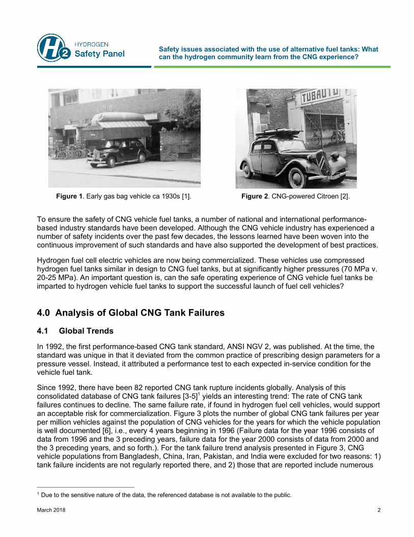
Natural gas was first used as a vehicle fuel as far back as the 1930s. The first natural gas vehicles, which ran on uncompressed natural gas, were called “gas bag” vehicles (Figure 1) and were used to combat gasoline shortages during World War I [1]. During and after World War II, compressed natural gas (CNG) vehicles using fuel tanks mounted on the roof (Figure 2) gained popularity in France and Italy [2]. Today, there are more than 24 million CNG vehicles in service worldwide, including CNG buses that continue the early tradition of mounting fuel tanks on the roof.
Safety issues associated with the use of alternative fuel tanks: What can the hydrogen community learn from the CNG experience?
March 2018 2
Figure 1. Early gas bag vehicle ca 1930s [1]. Figure 2. CNG-powered Citroen [2].
To ensure the safety of CNG vehicle fuel tanks, a number of national and international performance-based industry standards have been developed. Although the CNG vehicle industry has experienced a number of safety incidents over the past few decades, the lessons learned have been woven into the continuous improvement of such standards and have also supported the development of best practices.
Hydrogen fuel cell electric vehicles are now being commercialized. These vehicles use compressed hydrogen fuel tanks similar in design to CNG fuel tanks, but at significantly higher pressures (70 MPa v. 20-25 MPa). An important question is, can the safe operating experience of CNG vehicle fuel tanks be imparted to hydrogen vehicle fuel tanks to support the successful launch of fuel cell vehicles?
4.0 Analysis of Global CNG Tank Failures
4.1 Global Trends
In 1992, the first performance-based CNG tank standard, ANSI NGV 2, was published. At the time, the standard was unique in that it deviated from the common practice of prescribing design parameters for a pressure vessel. Instead, it attributed a performance test to each expected in-service condition for the vehicle fuel tank.
Since 1992, there have been 82 reported CNG tank rupture incidents globally. Analysis of this consolidated database of CNG tank failures [3-5]1 yields an interesting trend: The rate of CNG tank failures continues to decline. The same failure rate, if found in hydrogen fuel cell vehicles, would support an acceptable risk for commercialization. Figure 3 plots the number of global CNG tank failures per year per million vehicles against the population of CNG vehicles for the years for which the vehicle population is well documented [6], i.e., every 4 years beginning in 1996 (Failure data for the year 1996 consists of data from 1996 and the 3 preceding years, failure data for the year 2000 consists of data from 2000 and the 3 preceding years, and so forth.). For the tank failure trend analysis presented in Figure 3, CNG vehicle populations from Bangladesh, China, Iran, Pakistan, and India were excluded for two reasons: 1) tank failure incidents are not regularly reported there, and 2) those that are reported include numerous
1 Due to the sensitive nature of the data, the referenced database is not available to the public.

Safety issues associated with the use of alternative fuel tanks: What can the hydrogen community learn from the CNG experience?
March 2018 3
instances of the use of unauthorized pressure vessels (liquefied petroleum gas [LPG], re-worked, or repaired vessels).
Figure 3. Global CNG tank failures per year per million vehicles showing publication dates of key performance-
based CNG tank standards [3-5].
As of 2016, the failure rate is trending toward approximately 0.1 ruptures per million vehicles, or 1 rupture per 10 million vehicles. The introduction of additional performance-based standards in Canada (CSA B51 Part 2) in 1995 and the development of an International Standard (ISO 11439) in 2000 have positively affected the trend. In 2001, the European Union adopted a draft version of ISO 11439 for the ECE R110 regulation on CNG vehicles. ANSI NGV 2 was improved in 1998, 2000, 2007, and 2016, whereas ISO 11439 was republished in 2013. As discussed later in this paper, the recent development of hydrogen tank testing protocols that further refine and improve upon the performance-based philosophy of CNG tank test standards will be instrumental in ensuring a safe hydrogen vehicle industry.
4.2 Failure Modes
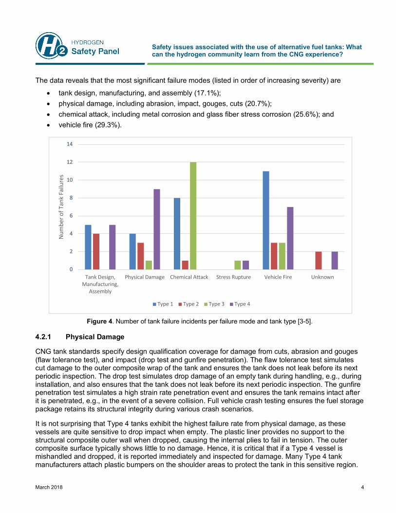
The consolidated database was further analyzed to discern the failure modes for the reported tank ruptures. The goal was to identify gaps in current CNG tank performance standards. Figure 4 shows the number of tank failure incidents per failure mode and per tank type. Tank type refers to the general construction of the pressure vessel and includes the following four types:
• Type 1 – all metal construction • Type 2 – metal liner construction and hoop-wrapped with resin impregnated continuous filaments • Type 3 – metal liner construction and fully-wrapped with resin impregnated continuous filaments • Type 4 – plastic liner construction and fully-wrapped with resin impregnated continuous filaments
Safety issues associated with the use of alternative fuel tanks: What can the hydrogen community learn from the CNG experience?
March 2018 4
The data reveals that the most significant failure modes (listed in order of increasing severity) are
• tank design, manufacturing, and assembly (17.1%); • physical damage, including abrasion, impact, gouges, cuts (20.7%); • chemical attack, including metal corrosion and glass fiber stress corrosion (25.6%); and • vehicle fire (29.3%).
Figure 4. Number of tank failure incidents per failure mode and tank type [3-5].
4.2.1 Physical Damage
CNG tank standards specify design qualification coverage for damage from cuts, abrasion and gouges (flaw tolerance test), and impact (drop test and gunfire penetration). The flaw tolerance test simulates cut damage to the outer composite wrap of the tank and ensures the tank does not leak before its next periodic inspection. The drop test simulates drop damage of an empty tank during handling, e.g., during installation, and also ensures that the tank does not leak before its next periodic inspection. The gunfire penetration test simulates a high strain rate penetration event and ensures the tank remains intact after it is penetrated, e.g., in the event of a severe collision. Full vehicle crash testing ensures the fuel storage package retains its structural integrity during various crash scenarios.
It is not surprising that Type 4 tanks exhibit the highest failure rate from physical damage, as these vessels are quite sensitive to drop impact when empty. The plastic liner provides no support to the structural composite outer wall when dropped, causing the internal plies to fail in tension. The outer composite surface typically shows little to no damage. Hence, it is critical that if a Type 4 vessel is mishandled and dropped, it is reported immediately and inspected for damage. Many Type 4 tank manufacturers attach plastic bumpers on the shoulder areas to protect the tank in this sensitive region.
Tank Design,Manufacturing,
Assembly
Physical Damage Chemical Attack Stress Rupture Vehicle Fire Unknown
Num
ber o
f Tan
k Fa
ilure
s
Type 1 Type 2 Type 3 Type 4
Safety issues associated with the use of alternative fuel tanks: What can the hydrogen community learn from the CNG experience?
March 2018 5
4.2.2 Tank Design, Manufacturing, and Assembly
The very nature of performance-based standards is such that poor designs are weeded out during the design qualification testing phase. CNG tank failures attributed to design issues have generally occurred in countries that have not adopted performance-based industry standards (e.g., Argentina and China). Today, nearly all CNG tanks are qualified to performance-based industry standards or regulations.
CNG tank standards have adequate coverage to mitigate tank failures arising from manufacturing issues since manufacturing quality control, including inspection and testing procedures, is well established in these documents. A lapse in quality control processes is the typical root cause for tanks that have ruptured due to a manufacturing issue.
CNG tank failures attributed to poor assembly or installation are expected to become increasingly rare due to the recent publication of a best practices document, CSA NGV 6.1, “Compressed Natural Gas (CNG) fuel storage and delivery systems for road vehicles.” The recommended practice applies to the design, installation, inspection, repair, and maintenance of fuel storage and delivery systems. The document is supplemental to both NFPA 52, “Vehicular Natural Gas Fuel Systems Code,” in the United States and CSA B109 Part 1, “Natural gas for vehicles installation code,” in Canada.
4.2.3 Chemical Attack
CNG tank failures due to chemical attack can be divided into two categories: 1) external corrosion of Type 1 (all-metal) tanks and Type 2 (hoop-wrapped) liners, and 2) stress corrosion cracking of the glass fibers on Type 3 (fully-wrapped) tanks. Both failure modes have been largely addressed in CNG tank standards via the addition of new performance-based test procedures to simulate an accelerated cycling corrosion environment for the former, and an environmental test to simulate exposure to acids, bases, and other automotive chemicals for the latter.
4.2.4 Stress Rupture
Very few CNG tanks fail by virtue of stress rupture. The stress rupture of composite wrapped CNG tanks was first reported in the early 1990s, when certain Type 2 tanks experienced failures of the glass fiber composite overwrap arising from high stresses imparted to the fibers during manufacture involving a high-tension filament winding process. Other glass fiber wrapped composite CNG tanks have experienced stress rupture failures due to abnormally high stresses in the glass fibers after autofrettage. The stress rupture failure mode is accounted for via the specification of minimum fiber stress ratios in CNG tank standards (depending on fiber type). In addition, the standards specify a stress rupture test consisting of subjecting the test vessel to a combination of elevated temperature and pressure for 1,000 hours followed by a burst test.
4.2.5 Vehicle Fire
Vehicle fire accounts for the largest percentage of CNG tank failures, and it is the lone remaining failure mode whose resolution eludes the industry. The primary reason is that none of the fire test specifications in any existing fire test requirements for pressure vessels is sufficient to reproducibly simulate vehicle fire conditions. Localized vehicle fires also continue to plague both light duty and heavy duty CNG vehicles.
Safety issues associated with the use of alternative fuel tanks: What can the hydrogen community learn from the CNG experience?
March 2018 6
5.0 Vehicle Fires and Localized Effects
5.1 Bonfire Test
Vehicular fires are a known in-service stressor for CNG vehicle tanks. When a pressurized vehicle tank is exposed to excessive heat arising from a vehicle fire, the tank materials begin to degrade and the pressure increases. In this scenario, the tanks are protected from rupture via a pressure relief device (PRD) that releases the fuel either by overpressure (in the case of a burst disk device [P-PRD]) or over-temperature (in the case of a thermally activated device [T-PRD]). Although P-PRDs have been used successfully to protect Type 1 pressure vessels in some applications, they have proven to be largely ineffective in protecting CNG vehicle tanks in a fire. When the P-PRD is exposed to a fire the burst disk begins to anneal, lowering its strength to the point where the increasing pressure in the tank will cause it to burst and vent the contents. Composite wrapped CNG tanks (Types 2, 3 and 4) do not increase in pressure as significantly as Type 1 tanks, nor do they have the same withstand resistance as Type 1 tanks in a fire. For the case of partially full tanks, P-PRDs will not activate at all. As a result, CNG vehicle tanks are protected from the effects of fire almost exclusively through the use of T-PRDs. The use of P-PRDs in CNG vehicle applications has now been generally relegated to the over-pressure protection of the tank arising from a fueling infrastructure fault.
In a fire, the T-PRD must demonstrate its ability to activate quickly and exhibit sufficient flow capacity so as to completely vent the tank before it ruptures. This service condition is simulated in performance-based CNG tank standards by a bonfire test. The bonfire test was adapted from several old U.S. Department of Transportation specifications for a 1.65 m long burner test for industrial composite cylinders (DOT FRP-1 and DOT FRP-2). The 1.65 m length was adopted by the CNG vehicle industry and believed to be representative of actual vehicle fires. The CNG standard tank fire can be generated using any fuel type including gasoline, diesel, and propane. However, two of three thermocouples positioned 25 mm below the surface of the tank must achieve an average temperature of 430°C over any 1-minute interval during the first five minutes of the test. Unfortunately, different fuel types have different thermal emissivities, resulting in different heat input into the test article. In addition, each fuel type can create a different fire “shape factor.” For example, a diesel pan fire manifests itself as a billowing and voluminous “bonfire” fully engulfing the test article, creating a potentially less conservative result since the T-PRD will always be fully engulfed and will activate quickly. In contrast, a propane burner fire typically stays within the 1.65 m length and below the test article, typically resulting in a more conservative result.
For the case of CNG tanks exceeding the 1.65 m burner length specified in standards and regulations, there exists an opportunity for selective interpretation of the test requirements. Long tanks that are fitted with a T-PRD at one end of the tank are positioned so that the center of the 1.65 m long fire source is 0.825 m from the non-T-PRD end of the container. Long tanks that are fitted with multiple T-PRDs along the length are positioned so that the center of the 1.65 m fire source is midway between the two T-PRDs that are separated by the greatest distance. Tanks longer than 1.65 m that are protected by T-PRDs at both ends will likely fail the bonfire test because the T-PRDs will not detect sufficient heat from the fire. Failure may be avoided by changing the T-PRD installation for the fire test, e.g., by plumbing the T-PRD down the side of the tank to be within 1.65 m of the other T-PRD and thereby fully exposing it or both to the fire. When these tanks are installed in service, the T-PRDs may not necessarily be installed as they were tested. In fact, there is a high probability that they will be installed at both ends of the long CNG tank, leaving the entire midsection of the tank exposed to a localized fire threat.

Safety issues associated with the use of alternative fuel tanks: What can the hydrogen community learn from the CNG experience?
March 2018 7
Vehicle fires can manifest themselves in many ways: fuel pool fire underneath the vehicle, internal passenger compartment fire, engine compartment fire, transported load fire, and tire fire, among others. It is impossible to assume that such fires will always create a perfect “bonfire test” scenario where the point source fire protection device (T-PRD) will activate. It is more likely that CNG tanks will experience flame impingement or localized fire, thus leaving T-PRD activation to chance. The combination of an assumed 1.65 m fire using a variable fuel source to simulate a vehicle fire, along with point source fire protection charged with mitigating against fires of various sizes, durations, intensities, and exposure locations, is the “perfect storm” for an increased probability of tank failure in vehicle fires.
5.2 Localized/Engulfing Fire Test
In response to the continued rash of CNG tank failures arising from localized vehicle fires, the SAE Fuel Cell Safety Committee developed a combined localized/engulfing fire test that was eventually adopted by the UN GTR 13 regulation, “Global Technical Regulation on Hydrogen and Fuel Cell Vehicles.” The test procedure was specifically developed for light duty vehicles as it was based on light duty vehicle fire test data from the Japanese Automobile Research Institute (JARI) and U.S. vehicle manufacturers [7].
The development of the localized/engulfing fire test procedure is described in UN GTR 13 and is summarized below.
The findings from the vehicle fire test data from JARI and the U.S. vehicle manufacturers were as follows:
• About 40% of the vehicle laboratory fires investigated resulted in conditions that could be categorized as a localized fire since the data indicated that a composite compressed gas tank could have been locally degraded before conventional T-PRDs on end bosses (away from the local fire exposure) would have activated. A temperature of 300°C was selected as the temperature where the localized fire condition could start because thermal gravimetric analysis indicated that tank materials begin to degrade rapidly at this temperature.
• While vehicle laboratory fires often lasted 30-60 minutes, the period of localized fire degradation on the storage containers lasted less than 10 minutes.
• The average of the maximum temperature during the localized fire period was less than 570°C, with peak temperatures reaching approximately between 600°C and 880°C in some cases.
• The rise in peak temperature near the end of the localized fire period often signaled the transition to an engulfing fire condition.
Based on the above findings, the temperature profile in Figure 5 was adopted. The selection of 600°C as the minimum temperature for the localized fire hold period ensured that the average temperature and time of localized fire test exposure were consistent with the test data. Thermocouples located 25 mm ± 10 mm from the outside surface of the test article were used to control the heat input and confirm that the required temperature profile was met. In order to improve the response and controllability of the fire during testing, the use of LPG and wind guards were specified.
Safety issues associated with the use of alternative fuel tanks: What can the hydrogen community learn from the CNG experience?
March 2018 8
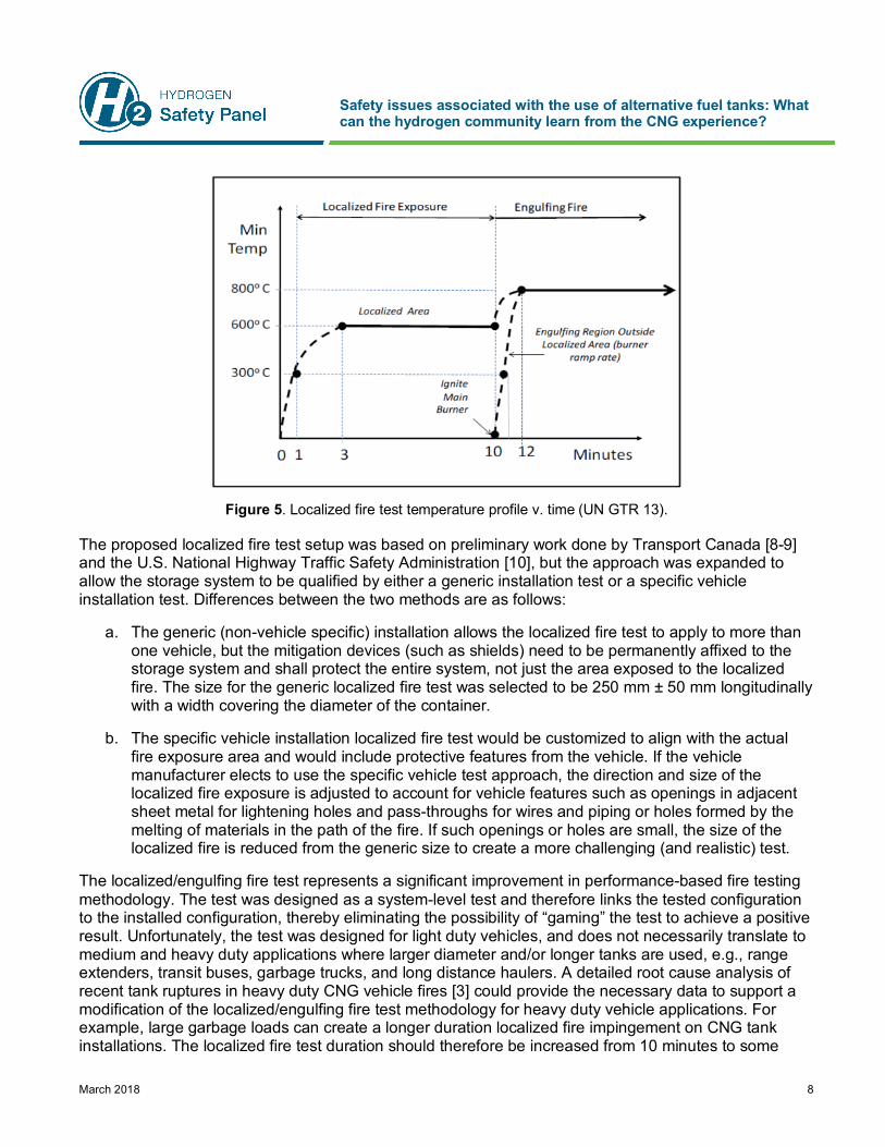
Figure 5. Localized fire test temperature profile v. time (UN GTR 13).
The proposed localized fire test setup was based on preliminary work done by Transport Canada [8-9] and the U.S. National Highway Traffic Safety Administration [10], but the approach was expanded to allow the storage system to be qualified by either a generic installation test or a specific vehicle installation test. Differences between the two methods are as follows:
a. The generic (non-vehicle specific) installation allows the localized fire test to apply to more than one vehicle, but the mitigation devices (such as shields) need to be permanently affixed to the storage system and shall protect the entire system, not just the area exposed to the localized fire. The size for the generic localized fire test was selected to be 250 mm ± 50 mm longitudinally with a width covering the diameter of the container.
b. The specific vehicle installation localized fire test would be customized to align with the actual fire exposure area and would include protective features from the vehicle. If the vehicle manufacturer elects to use the specific vehicle test approach, the direction and size of the localized fire exposure is adjusted to account for vehicle features such as openings in adjacent sheet metal for lightening holes and pass-throughs for wires and piping or holes formed by the melting of materials in the path of the fire. If such openings or holes are small, the size of the localized fire is reduced from the generic size to create a more challenging (and realistic) test.
The localized/engulfing fire test represents a significant improvement in performance-based fire testing methodology. The test was designed as a system-level test and therefore links the tested configuration to the installed configuration, thereby eliminating the possibility of “gaming” the test to achieve a positive result. Unfortunately, the test was designed for light duty vehicles, and does not necessarily translate to medium and heavy duty applications where larger diameter and/or longer tanks are used, e.g., range extenders, transit buses, garbage trucks, and long distance haulers. A detailed root cause analysis of recent tank ruptures in heavy duty CNG vehicle fires [3] could provide the necessary data to support a modification of the localized/engulfing fire test methodology for heavy duty vehicle applications. For example, large garbage loads can create a longer duration localized fire impingement on CNG tank installations. The localized fire test duration should therefore be increased from 10 minutes to some
Safety issues associated with the use of alternative fuel tanks: What can the hydrogen community learn from the CNG experience?
March 2018 9
higher value. The root cause analysis should also attempt to inform changes to the dimensions of the 1.65 m long fire source. For example, is it fair to assume the width of the fire equals the width of the tank? Presumably, the fire dimensions should be standardized.
Although the original intent of specifying the use of LPG fuel for the localized/engulfing fire test was to improve the reproducibility of test results, actual testing experience has shown that significant lab-to-lab variability exists. The issue lies in the fact that specifying a fire temperature profile alone does not guarantee the same heat input from test article to test article. Other industries where withstanding fire is a critical performance consideration specify an additional fire test parameter in the procedure.
The thermal exposure requirements for a container designed to transport nuclear material must comply with the U.S. Nuclear Regulatory Commission 10 CFR 71.73, “Hypothetical accident conditions,” which requires a hydrocarbon fuel/air fire of sufficient extent to provide an average emissivity coefficient of at least 0.9, with an average flame temperature of at least 800°C for a period of 30 minutes. The fuel source dimension is defined as extending at least 1 m, but not more than 3 m, beyond any external surface of the test article, and the test article must be positioned 1 m above the surface of the fuel source.
A key difference in the fire testing methodologies is the specification of a fire emissivity coefficient for the case of the radioactive material container. An emissivity coefficient of 0.9 equates to a total heat flux of approximately 90 kW/m2. In comparison, the total heat flux for large pool fires with engulfed objects is 100 kW/m2. The addition of a heat flux specification to the localized/engulfing fire test may be all that is required to resolve lab-to-lab test variability with the current methodology. The curved shape of the test specimen should also be considered when specifying heat flux requirements. Preliminary localized fire tests conducted at CSA Group [11] using a heat flux sensor installed at the six o’clock position on a CNG tank exposed to 800°C flame temperatures yielded a heat flux of 117-165 kW/m2. The variability was due to swirling wind effects during the experiment, which would not be expected during a standard test under the required quiescent conditions.
Another way of resolving the issue of lab-to-lab test variability is to specify the design of the fire test apparatus (including length and width), and specify the LPG flow rate during the localized and engulfing portions of the test. This approach would require industry consensus on the burner design and LPG flow rates.
5.3 Fire Withstand Resistance
The concept of fire withstand resistance is an additional consideration in the debate surrounding the efficacy of simulated vehicle fire tests to demonstrate fire safety through T-PRD protection. Fuel tanks can be protected from fire effects by thermal insulation or other vehicle level protection systems. In these cases, the fuel contents would not be evacuated from the tank. A disadvantage is that, depending on the length, intensity, and duration of the fire impinging on the fuel tank, there is a possibility that at the termination of the fire threat, the fuel storage system would be in a potentially weakened state, leaving second and third responders with the issue of defueling a possibly weakened pressure vessel.
The demonstration of fire withstand resistance would still require subjecting the test article to a localized/engulfing fire test procedure, but the goal would be to specify a total withstand duration representative of worst case vehicle or cargo fire (e.g., 30 minutes? 60 minutes?). Determining this value would require an analysis of vehicle fire durations.
Safety issues associated with the use of alternative fuel tanks: What can the hydrogen community learn from the CNG experience?
March 2018 10
6.0 CNG Tank Inspection, Maintenance, and End of Life Considerations
CNG tank inspection is critical to ensuring the in-service safety of CNG tanks. Inspection is a component that is factored into performance standards such as ANSI NGV 2 since certain test parameters and acceptance criteria were developed with the assumption that fuel tanks would be inspected in accordance with the standard requirement, i.e., using a recognized inspection standard in combination with the manufacturer’s inspection criteria every 3 years or 36,000 miles, whichever comes first. Unfortunately, many CNG tanks are not being periodically inspected due to a lack of jurisdictional enforcement, and so it is left to the various fleet managers and private owners to do the prudent thing and get their tanks inspected every 3 years or less. Apart from the obvious safety benefits, periodic tank inspection/requalification also mitigates owner liability in the event of a tank failure.
Hydrogen vehicle tank standards are silent on the subject of periodic tank inspection. This is because the thinking is that the vast majority of hydrogen vehicles will be developed, produced, and launched by vehicle original equipment manufacturers (OEMs) who have the means to develop and package safe fuel storage systems. Hydrogen tank testing protocols are considered to be more stringent than those found in CNG tank standards. For example, SAE J2579 and the UN GTR 13 regulation consider the cumulative effect of multiple in-service stressors on hydrogen fuel tanks, resulting in presumably more robust tanks. This design qualification approach, combined with vehicle OEM design principles where the fuel storage system is protected and therefore less susceptible to damage, justifies the elimination of periodic tank inspection. An inspection of the fuel storage system is still required if the vehicle has been involved in a collision or fire.
Pressurized fuel systems should only be handled by trained personnel – a fatality that occurred when a pressurized valve was ejected from a tank as it was being removed for maintenance spurred the CNG vehicle industry into action, resulting in the creation of CSA NGV 6.1. Perhaps at a minimum, the hydrogen vehicle industry should consider developing a hydrogen version to promote safe maintenance and repair practices. For example, the temperatures achieved in vehicle paint and drying booths may exceed the activation temperature of the T-PRD. This would not be a typical consideration for a gasoline powered vehicle.
Tank end of life has also recently become a significant topic of discussion as more CNG tanks approach their 15 to 20 year end of life. Ensuring the safe defueling, decommissioning, and disposal of time-expired or damaged CNG tanks is now possible via a new CSA express document (CSA EXP 2.1). The document is intended to be used by industry, tank manufacturers, and authorities having jurisdiction to safely and effectively remove CNG tanks from service. A similar hydrogen version should be developed by the hydrogen vehicle industry.
7.0 Research and Testing Gaps
It is clear that the hydrogen vehicle industry has already reaped the benefits of the CNG vehicle industry’s approach of developing performance-based industry standards. An analysis of CNG tank failures since 1992 reveals that the rate of CNG tank failures continues to fall and is approaching acceptable levels for the commercialization of hydrogen fuel cell vehicles. This is largely due to the continual improvement of CNG tank standards. Hydrogen tank standards have gone a step further by refining the approach to include a more severe sequential/cumulative stressor testing protocol, as well as adopting a systems-based approach to design qualification. In response to the continued rash of CNG tank failures arising from localized vehicle fires, the hydrogen vehicle industry has developed an
Safety issues associated with the use of alternative fuel tanks: What can the hydrogen community learn from the CNG experience?
March 2018 11
improved localized/engulfing fire test to simulate such service conditions. Suggested further refinements to the testing methodology that require additional study include the following:
1. Perform a detailed root cause analysis of recent tank ruptures in heavy duty CNG vehicle fires to provide the necessary data to support a modification of the localized/engulfing fire test methodology for medium and heavy duty vehicle applications. Determine if T-PRD activation time was a factor and consider specifying a minimum activation time in T-PRD component-level standards.
2. Add a heat flux specification to the localized and engulfing portions of the fire test (while considering the curved shape of the test specimen), or specify both the design of the fire test apparatus (including length and width) and the LPG flow rate during the localized and engulfing portions of the fire test.
3. Evaluate the concept of fuel tank fire withstand resistance in a vehicle fire.
Additional recommendations to fill the gaps identified to promote the safe life cycle of hydrogen fuel tanks include the following:
1. Develop a recommended practice for the design, installation, inspection, repair, and maintenance of hydrogen fuel storage and delivery systems, similar to CSA NGV 6.1.
2. Develop guidelines for the safe defueling, decommissioning, and disposal of time-expired or damaged hydrogen tanks.
8.0 Other Applications
This paper discusses the standards and regulations for vehicle fuel tanks as applicable to CNG and hydrogen powered vehicles. Other applications where pressure vessels are not used for providing motive power, such as in the transportation of compressed gases, mobile fuelers, auxiliary power units, etc., should not reference the standards and regulations indicated herein to validate their acceptability or safe use without further study and validation.
9.0 References
1. CNG Complete. 2014. “A Natural Gas History.” http://www.cngcomplete.com/blog/natural-gas-history-vehicles/
2. Low-Tech Magazine (undated), “Gas Bag Vehicles,” http://www.lowtechmagazine.com/2011/11/gas-bag-vehicles.html.
3. Bowerson, D., NGV America, personal communication, October 24, 2017. 4. Webster, C., CSA Group, personal communication, December 18, 2017. 5. Scheffler, G., GWS Solutions of Tolland, LLC, personal communication, March 15, 2017. 6. NGV Global. 2017. “Natural Gas Vehicles by Country,” http://www.iangv.org/current-ngv-stats/. 7. Scheffler, G., McClory, M. et al., “Establishing Localized Fire Test Methods and Progressing
Safety Standards for FCVs and Hydrogen Vehicles,” SAE Technical Paper 2011-01-0251.
Safety issues associated with the use of alternative fuel tanks: What can the hydrogen community learn from the CNG experience?
March 2018 12
8. Gambone, L. et al. 2008. “Hydrogen Vehicle Fuel Systems – Localized Fire Protection Considerations, Milestone 2, Vehicle Fire Condition Report, Report to Transport Canada Road Safety, February 29, 2008.
9. Webster, C. 2008. “Hydrogen Vehicle Fuel Systems – Localized Fire Protection Considerations, Milestone 3, Localized Fire Test Procedure,” Report to Transport Canada Road Safety, March 30, 2008.
10. Webster, C. 2010. “Localized Fire Protection Assessment for Vehicle Compressed Hydrogen Containers”, Report to DOT NHTSA, Report DOT HS 811 303, March 2010.
11. Gambone, L. 2016. Data presented at the 23rd Hydrogen Safety Panel Meeting, Washington, DC, November 16, 2016.
Disclaimer: This document was were prepared as an account of work sponsored by an agency of the United States Government. Neither the United States Government nor any agency thereof, nor Battelle Memorial Institute, nor any of their employees, makes any warranty, express or implied, or assumes any legal liability or responsibility for the accuracy, completeness, or usefulness of any information, apparatus, product, or process disclosed, or represents that its use would not infringe privately owned rights. Reference herein to any specific commercial product, process, or service by trade name, trademark, manufacturer, or otherwise does not necessarily constitute or imply its endorsement, recommendation, or favoring by the United States Government or any agency thereof, or Battelle Memorial Institute. The views and opinions of authors expressed herein do not necessarily state or reflect those of the United States Government or any agency thereof. Additionally, the document does not provide any approval or endorsement by the United States Government, Battelle, or the Hydrogen Safety Panel of any system(s), material(s) or equipment discussed in the report.