Embed Size (px)
Citation preview
harwin.com
Harwin Test Report Summary
HT04301
M300 Connector Series Testing Electrical, Mechanical & Environmental

2 Issue: 1 Date: 17/03/2015 C/Note: -----
HT04301 M300 Connector Series, Electrical, Mechanical & Environmental Testing
1. Introduction.
1.1. Description and Purpose. The Harwin M300 Series is a range of High Reliability 5 & 10A Power connectors on a 3mm pitch. The following tests were carried out to establish or validate the claims made in the M300 component specification CO48XX (where XX is issue 01, 02 etc.).
1.2. Conclusion. The following data has been collated from Harwin test report 1106, with additional dimensional verification to be found in reports 1089-92, 1097-99 and 1101. The connectors met the test requirements set out in section 2.3 of this test report summary – all electrical, mechanical and environmental requirements were fulfilled. These results are representative of all the M300 series connectors. Further information available on request – please contact [email protected].
2. Test Method, Requirements and Results.
2.1. List of Test Samples. a) M300-FV1034500 - Female Vertical SIL 3 Position PC Tail Connector.
b) M300-FV3064500 - Female Vertical DIL 6 Position PC Tail Connector.
c) M300-MV10345M1 - Male Vertical SIL 3 Position PC Tail Connector with Jackscrew.
d) M300-MV30645M1 - Male Vertical DIL 6 Position PC Tail Connector Jackscrew.
e) M300-0010045 - Female 18/20 AWG Cable Crimp Contacts.
f) M300-0020045 - Female 22 AWG Cable Crimp Contacts.
g) M300-1010045 - Male 18/20 AWG Cable Crimp Contacts.
h) M300-1020045 - Male 22 AWG Cable Crimp Contacts.
i) M300-2240600F2 - Female Cable DIL 6 Position Housing with Jackscrew.
j) M300-2250300F2 - Female Cable SIL 3 Position Housing with Jackscrew.
k) M300-3240600M1 - Male Cable DIL 6 Position Housing with Jackscrew.
l) M300-3250300M1 - Male Cable SIL 3 Position Housing with Jackscrew.
2.2. Specification Parameters. Tests were carried out in accordance with the following standards:
Testing Standard Description of Test Page No.
EIA-364-01B: 2000 Acceleration: Test Condition A 3
EIA-364-05B: 1998 Contact Insertion, Release and Removal force in Housing 4
EIA-364-08B: 1998 Crimp Tensile Strength 5
EIA-364-09C: 1999 Durability (Mechanical Operations) 6
EIA-364-13C: 2006 Mating and Un-Mating Forces: Test Method B 6
EIA-364-17B: 1999 Temperature Life: Test Method A, Condition 6D 7
EIA-364-20C: 2004 Withstanding Voltage (Proof): Test Method B, Conditions I & IV 8
EIA-364-21C: 2000 Insulation Resistance 8
EIA-364-23B: 2000 Low Level Contact Resistance 9

3 Issue: 1 Date: 17/03/2015 C/Note: -----
HT04301 M300 Connector Series, Electrical, Mechanical & Environmental Testing
EIA-364-28D: 2006 Vibration: Test Condition II and IV 9
EIA-364-31B: 2000 Humidity (Damp Heat): Test Method II, Conditions A and D 10
EIA-364-32C: 2000 Thermal Shock (Temperature Cycling): Test Condition V 11
EIA-364-70A: 1998 Temperature Rise v. Current (Power Rating): Test Method 2 11
BS EN 60068-2-27: 2009 Environmental Testing (Bump and Shock) 14
Note: BS EN 60068-2-27 is a replacement for obsolete standard EIA-364-27B – Bump and Shock.
2.3. Test Method and Results.
All testing was carried out using standard parts. For the mating force testing, Female Jackscrews were removed.
a) Acceleration to EIA-364-01A Test Condition A
Specification: 50G (490m/s²), 5 minutes, 3 Axes both directions.
Method: 2 samples of all types of connectors listed in section 2.1 in Cable-to-Board combinations, with a minimum of 200mm free length of 22 AWG wire assembled to the cable connectors. Mated pairs are mounted to the test equipment as shown. During this test, the samples were monitored continuously for discontinuity with a constant current source of 100mA DC. Parts were visually inspected for damage after testing.
A summary of the findings are as follows:
Mated Connector Pair Type Pass/Fail Visual Insp. Damage Observation
Female PC Tail / Male Cable SIL 3 Position No Jackscrew Pass Pass None
Female PC Tail / Male Cable DIL 6 Position No Jackscrew Pass Pass None
Female Cable / Male PC Tail SIL 3 Position With Jackscrew Pass Pass None
Female Cable / Male PC Tail DIL 6 Position With Jackscrew Pass Pass None

4 Issue: 1 Date: 17/03/2015 C/Note: -----
HT04301 M300 Connector Series, Electrical, Mechanical & Environmental Testing
b) Contact Insertion and Removal Force in Housing to EIA-364-05B
Specification: 45N max. Insertion / 15N min. Removal. (Specification will be increased.)
Method: 3 samples of all types of connectors listed in section 2.1 had contacts assembled to their specified assembly position in housings, while having the force required to insert each contact measured. Then the force required to remove the contact was also measured.
The average, maximum and minimum forces recorded for each type is as follows:
Connector Type Insertion Force (N) Removal Force (N)
Female Vertical PC Tail 73.1 avg., 93.3 max. 61.1 avg., 49.5 min.
Male Vertical PC Tail 53.3 avg., 67.7 max. 43.2 avg., 33.5 min.
Female Cable 57.2 avg., 71.1 max. 45.6 avg., 33.1 min.
Male Cable 59.4 avg., 72.3 max. 72.3 avg., 61.2 min.
c) Contact Replacement in Housing to EIA-364-05B
Specification: 2 Replacements minimum. (Specification will be increased.)
Method: 3 samples of all Cable types of connectors listed in section 2.1 had contacts assembled to their specified assembly position in housings, while having the force required to insert each contact measured. Then the force required to remove the contact also measured. This operation was then repeated using the same contacts and housings 10 times, or until the force required for removing contact fell below the minimum requirement of 15N.
The average, maximum and minimum forces recorded for each type is as follows:
Connector Type / Replacements Insertion Force (N) Removal Force (N)
Female Cable 1st Operation 52.6 avg., 63.1 max. 44.7 avg., 31.6 min.
Female Cable 3rd Operation 41.2 avg., 48.4 max. 35.9 avg., 27.7 min.
Female Cable 10th Operation 22.7 avg., 28.1 max. 21.8 avg., 16.1 min.
Male Cable 1st Operation 63.8 avg., 81.5 max. 72.3 avg., 59.1 min.
Male Cable 3rd Operation 45.1 avg., 53.9 max. 44.2 avg., 30.6 min.
Male Cable 10th Operation 23.4 avg., 29.9 max. 23.8 avg., 20.1 min.

5 Issue: 1 Date: 17/03/2015 C/Note: -----
HT04301 M300 Connector Series, Electrical, Mechanical & Environmental Testing
d) Contact Crimp Integrity to EIA-364-08B
Specification: 22 AWG = 50N min., 20 AWG = 80N min., 18 AWG = 140N min.
Method: 3 Samples of all types of Cable Crimp contacts listed in section 2.1 were assembled with the following types of wire as applicable:
• 22 AWG (19x0.15) BS 3G 210 Type A
• 20 AWG (19x0.20) BS 3G 210 Type A
• 18 AWG (19x0.25) MIL-16878 Type E
Crimping was completed using crimp tool M22520/2-01 (position 8) fitted with Z80-058 positioner. Parts were inspected for cracks under at least 10x magnification. The wire was then separated from the contact at a speed of 25mm per minute, and the force required to achieve separation of wire from contact recorded, as well as the type of separation (Wire Break or Pull Out). Samples were also micro sectioned to check for voids.
A summary of the findings are as follows:
Contact and Wire Type Crack
Inspection Pass/Fail
Void Inspection Pass/Fail
Wire Separation Force (Min.)
Separation Type
Female Contact with 18 AWG wire Pass Pass 186N Wire Break
Male Contact with 18 AWG wire Pass Pass 150N Wire Break
Female Contact with 20 AWG wire Pass Pass 106N Wire Break & Pull-Out
Male Contact with 20 AWG wire Pass Pass 119N Wire Break & Pull-Out
Female Contact with 22 AWG wire Pass Pass 50N Wire Break
Male Contact with 22 AWG wire Pass Pass 57N Wire Break

6 Issue: 1 Date: 17/03/2015 C/Note: -----
HT04301 M300 Connector Series, Electrical, Mechanical & Environmental Testing
e) Durability (Mechanical Operations) to EIA-364-09C
Specification: 1000 Operations.
Method: For this test, 3 sets of Female cable SIL 3 position connectors and mating Male PC Tail connectors were used (as listed in section 2.1). In separate tests, the mated pairs were clamped in a holding fixture, allowing one-half of the pair to float. Automatic of cycling took place at 25.4mm/minute, fully mating by 4.45mm after female enters male moulding, for 1000 cycles.
Contact Resistance, Insulation Resistance and Dielectric Withstanding Voltage were measured prior to cycling. Mating/Un-Mating forces were measured throughout cycling. After 10, 30, 50, 100, 200, 300, 400, 500, 750 and 1000 cycles, electrical tests and visual inspection took place. After 1000 cycles and other tests completed, Contact retention in housing also measured and recorded.
Result: No failures reported.
f) Mating and Un-Mating Force to EIA-364-13C
Specification: 9N max. mating (Insertion) force, 1N min. un-mating (Withdrawal) force per contact.
Method: 3 samples of all types of connectors listed in section 2.1, in separate tests, were clamped in holding fixture allowing one half of set to float. The pairs were then fully mated and un-mated at 25.4mm/minute (same setup as Durability). Peak mating and un-mating forces measured and recorded.
The average, maximum and minimum forces recorded for each type is as follows:
Mated Connector Pair Type Mating Force (N) Un-Mating Force (N) Pass/Fail
Female PC Tail / Male Cable SIL 3 Position 10.6 avg., 11.5 max. 8.3 avg., 7.7 min. Pass
Female Cable / Male Cable SIL 3 Position 15.0 avg., 16.9 max. 10.8 avg., 9.5 min. Pass
Female Cable / Male PC Tail SIL 3 Position 13.1 avg., 15.4 max. 9.2 avg., 8.4 min. Pass
Female PC Tail / Male PC Tail SIL 3 Position 10.6 avg., 11.6 max. 9.2 avg., 8.2 min. Pass
Female PC Tail / Male Cable DIL 6 Position 24.3 avg., 26.7 max. 18.5 avg., 17.4 min. Pass
Female Cable / Male Cable DIL 6 Position 21.2 avg., 21.7 max. 15.6 avg., 14.9 min. Pass
Female Cable / Male PC Tail DIL 6 Position 31.2 avg., 36.6 max. 18.3 avg., 16.1 min. Pass
Female PC Tail / Male PC Tail DIL 6 Position 21.0 avg., 23.1 max. 17.2 avg., 16.0 min. Pass
g) Temperature Life, Test Method A, Condition 6D to EIA-364-17B

7 Issue: 1 Date: 17/03/2015 C/Note: -----
HT04301 M300 Connector Series, Electrical, Mechanical & Environmental Testing
Specification: After conditioning at 175°C for 1000 hours the following specifications must be met: Un-mating force per contact = 1N min.; Contact resistance per contact = 25mΩ max.; Visual inspection to reveal no sign of cracking, crazing, delamination or damage caused by fusing or seizure; 15N min. contact removal force in housing; 50N min. contact crimp integrity pull out force on 22AWG wire and 140N on 18AWG.
Method: 12 samples of all cable connector assemblies listed in section 2.1 had 45cm of wire crimped to each contact: 6 with 18 AWG wire and 6 with 22 AWG. These were checked before conditioning that parts met specification. Half of these were then suspended as shown in an oven set at 175±5°C and remained there for 1000 hours. The remaining samples were then suspended in a similar manner but at normal ambient temperature for the same period of time.
After conditioning, samples were removed, visually inspected and checked that all properties were in specification. A summary of the findings are as follows:
Mated Connector Pair Type Un-Mate
Force Pass/Fail
Contact Resistance Pass/Fail
Contact Removal
Force Pass/Fail
Contact Crimp
Integrity Pass/Fail
Visual Inspection Pass/Fail
Female/Male Cable SIL 3 Pos. 18 AWG Pass Pass Pass Pass Pass
Female/Male Cable SIL 3 Pos. 22 AWG Pass Pass Pass Pass Pass
Female/Male Cable DIL 6 Pos. 18 AWG Pass Pass Pass Pass Pass
Female/Male Cable DIL 6 Pos. 22 AWG Pass Pass Pass Pass Pass
Note: Visual Inspection showed housings conditioned at 175°C darkened in colour due to Oxidation. But Electrical and Mechanical properties were not significantly affected.
Assemblies Suspended in Oven

8 Issue: 1 Date: 17/03/2015 C/Note: -----
HT04301 M300 Connector Series, Electrical, Mechanical & Environmental Testing
h) Withstanding Voltage (Proof) Test Method B, Conditions I and IV to EIA-364-20C
Specification: Condition I (Sea Level 913/1050mb) = 1200V DC min. and Condition IV (Altitude 70,000ft. / 44mb max.) = 300V DC min. (Specification will be increased.)
Method: 3 Samples of all types of connectors listed in section 2.1 were mated with connectors that had all adjacent contacts linked in series with 22 AWG wire. A voltage was passed through all contacts and maintained for 60 seconds – this was raised at 500V per second to various test voltages, each level maintained for 60 seconds. Voltage is then reduced back to zero, while being monitored for leakage current not to exceed 5mA, or evidence of disruptive discharge (Flashover or Spark).
A summary of the findings are as follows:
Connector Type 300V DC Altitude Pass/Fail
400V DC Altitude Pass/Fail
450V DC Altitude Pass/Fail
1200V DC Sea Level Pass/Fail
1600V DC Sea Level Pass/Fail
1800V DC Sea Level Pass/Fail
All Single Row Female Conn. Pass Pass Pass Pass Pass Pass
All Dual Row Female Conn. Pass Pass Pass Pass Pass Pass
All Single Row Male Conn. Pass Pass Pass Pass Pass Pass
All Dual Row Male Conn. Pass Pass Pass Pass Pass Pass
i) Insulation Resistance to EIA-364-21C
Specification: 100MΩ min. at 500V DC. (Specification will be increased.)
Method: 3 Samples of all types of connectors listed in section 2.1 were assembled with 22 AWG, BS 3G 210 Type A wire, so a voltage could be passed through all adjacent contacts. Results were monitored using a Megger MIT400 insulation tester, set at 500V DC for a 2 minute period. The test was then repeated at 1000V DC.
j) Low Level Contact Resistance to EIA-364-23C
Specification: 25mΩ max. (Specification will be reduced.)
Method: Unused mated combinations (shown in the table below), made from the connectors listed in section 2.1 were prepared by attaching 100mm of 18 AWG (19/30) MIL-16878E Type E wire to all contacts.
Using a Fluke 8808A multimeter, the test current was set at 100mA max., 20mV open circuit (source) voltage max. The resistance of two of the 100mm lengths of the 18AWG wire only were measured, to establish the wire resistance alone.
Connectors were mated for the first time, then each mated contact (including wire) measured for resistance. The initial results were recorded as this reading minus the wire resistance. The connectors were then separated and mated for a second time, before re-measuring for an “After conditioning” result.
Results: All results for 500V DC were greater than 10,000MΩ. All results for 1000V DC were greater than 20,000MΩ.

9 Issue: 1 Date: 17/03/2015 C/Note: -----
HT04301 M300 Connector Series, Electrical, Mechanical & Environmental Testing
A summary of the findings are as follows:
Mated Connector Pair Type Contact Resistance (Initial)
Contact Resistance (After Conditioning) Pass/Fail
Female PC Tail / Male PC Tail SIL 3 Position 2mΩ max. 2mΩ max. Pass
Female PC Tail / Male Cable DIL 6 Position 2mΩ max. 2mΩ max. Pass
Female Cable / Male Cable DIL 6 Position 3mΩ max. 3mΩ max. Pass
Female Cable / Male PC Tail DIL 6 Position 3mΩ max. 3mΩ max. Pass
Female PC Tail / Male PC Tail DIL 6 Position 3mΩ max. 3mΩ max. Pass
k) Vibration Test Condition II and IV to EIA-364-28D
Specification: Condition II – 10Hz to 500Hz, 1.52mm, 98.1m/s² (10G), 9 hours. Specification will be increased.
Method: 2 samples of all types of connectors listed in section 2.1, in cable-to-board combinations, were subjected to above Condition II vibration in all 3 Axes, while being monitored for discontinuities of 1 millisecond or more using a constant current source of 100mA. Parts were visually inspected for damage or wear before and after. The same samples were then tested again to a higher level of vibration: Condition IV – 10Hz to 2000Hz, 1.52mm, 196.1m/ s² (20G), 12 hours.
X-axis typical setup Y-axis typical setup Z-axis typical setup.

10 Issue: 1 Date: 17/03/2015 C/Note: -----
HT04301 M300 Connector Series, Electrical, Mechanical & Environmental Testing
A summary of the findings are as follows:
Mated Connector Pair Type Condition II
(10G) Pass/Fail
Condition IV (20G)
Pass/Fail
Visual Insp. Damage/Wear Observation
Female PC Tail / Male Cable SIL 3 Position, no Jackscrew
Pass X, Z Fail Y
Pass X, Z Fail Y Pass Failure due to mated
pair separating Female PC Tail / Male Cable DIL
6 Position, no Jackscrew Pass Pass Pass None
Female Cable / Male PC Tail SIL 3 Position, with Jackscrew Pass Pass Pass None
Female Cable / Male PC Tail DIL 6 Position, with Jackscrew Pass Pass Pass None
l) Humidity (Damp Heat) Test Method II, Conditions A and D to EIA-364-31B
Specification: 96 hour or 56 day, 90% RH (relative humidity) at 40°C.
Method: Samples of all cable-to-board, mated and un-mated pairs of connectors listed in section 2.1 were prepared with sufficient lengths of wire, and suspended vertically in a drying oven while having a polarising voltage applied. They were subject to 50°C for 24 hours. Immediately after conditioning, the samples were measured for bulk contact resistance (including test circuit) in ambient conditions. The samples were returned to the test chamber with a 100V DC polarising voltage, a relative humidity of 90-95% and 40±2°C. After 96 hours, a sample of each type was removed, leaving the remaining samples to complete the 56 day period. Bulk contact resistance on 1 control sample was measured immediately after removal from the test chamber. All sampleswere measured after 5 hours (to recover to standard ambient conditions).
A summary of the findings are as follows:
Mated or Un-mated Connector Pair Type
Pre-Test bulk Contact Resistance
Post-Test bulk Contact Resistance
5 hrs Post-Test bulk Contact Resistance
Observations
Female Cable / Male PC Tail SIL 3 Position, Mated 0.138 Ω max. n/a 0.140 Ω max. None
Female PC Tail / Male Cable SIL 3 Position, Un-Mated 0.138 Ω max. n/a 0.140 Ω max. None
Female Cable / Male PC Tail DIL 6 Position, Mated 0.138 Ω max. 0.138 Ω max. 0.138 Ω max. None
Female PC Tail / Male Cable DIL 6 Position, Un-Mated 0.139 Ω max. n/a 0.141 Ω max. None
11 Issue: 1 Date: 17/03/2015 C/Note: -----
HT04301 M300 Connector Series, Electrical, Mechanical & Environmental Testing
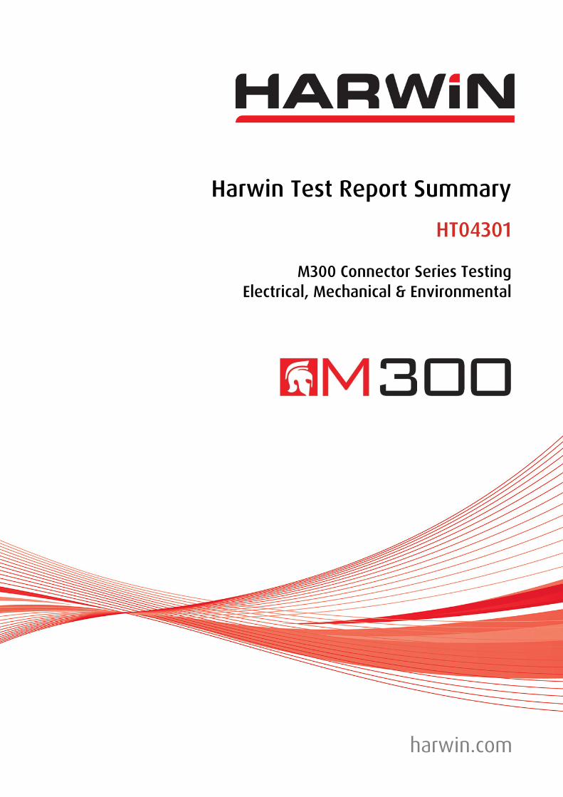
m) Thermal Shock (Temperature Cycling) Test Condition V to EIA-364-32C
Specification: +175/-65°C.
Method: Samples of all cable-to-board mated pairs of connectors listed in 2.1, prepared with sufficient lengths of wire, were checked for Mating/Un-Mating force, Voltage Proof, Insulation Resistance and Contact Resistance. Parts were also visually inspected for signs of damage, cracking, crazing or delamination of surfaces or finishes.
These samples were then placed in a Temperature Cycling oven as shown, cycled 5 times from +175/178°C to -65/70°C with dwell time 30 minutes min. Parts were then removed from the oven and allowed to return to ambient temperature before final checks were made.
A summary of the findings are as follows:
Mated Connector Pair Type Mate / Un-Mate Force Pass/Fail
Voltage Proof
Pass/Fail
Insulation Resistance Pass/Fail
Contact Resistance Pass/Fail
Visual Inspection Pass/Fail
Female Cable / Male PC Tail SIL 3 Pos. Pass Pass Pass Pass Pass
Female PC Tail / Male Cable SIL 3 Pos. Pass Pass Pass Pass Pass
Female Cable / Male PC Tail DIL 6 Pos. Pass Pass Pass Pass Pass
Female PC Tail / Male Cable DIL 6 Pos. Pass Pass Pass Pass Pass
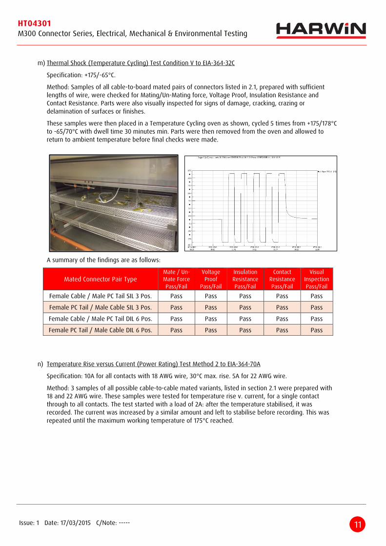
n) Temperature Rise versus Current (Power Rating) Test Method 2 to EIA-364-70A
Specification: 10A for all contacts with 18 AWG wire, 30°C max. rise. 5A for 22 AWG wire.
Method: 3 samples of all possible cable-to-cable mated variants, listed in section 2.1 were prepared with 18 and 22 AWG wire. These samples were tested for temperature rise v. current, for a single contact through to all contacts. The test started with a load of 2A: after the temperature stabilised, it was recorded. The current was increased by a similar amount and left to stabilise before recording. This was repeated until the maximum working temperature of 175°C reached.
12 Issue: 1 Date: 17/03/2015 C/Note: -----
HT04301 M300 Connector Series, Electrical, Mechanical & Environmental Testing
0
5
10
15
20
25
30
35
10 20 30 40 50 60 70 80 90 100 110 120 130 140 150 160 170 180
Current (A)
AmbientTemperature (°C)
Derate Curves for Current versus Ambient Temperature18 AWG Contact
1 Contact
3 Contacts
6 Contacts
Max. Operating temperature
0
20
40
60
80
100
120
140
160
180
2 4 6 8 10 12 14 16 18 20 22 24 26 28 30 32
T-Rise (°C)
Current (A)
Temperature Rise versus Current18 AWG Contact
1 Contact
3 Contacts
6 Contacts
The following temperature rise and de-rate curve graphs were produced from the recorded results:
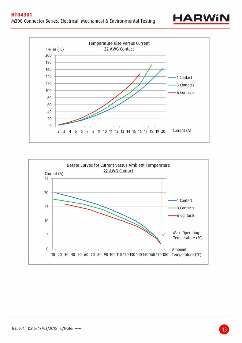
13 Issue: 1 Date: 17/03/2015 C/Note: -----
HT04301 M300 Connector Series, Electrical, Mechanical & Environmental Testing
0
20
40
60
80
100
120
140
160
180
200
2 3 4 5 6 7 8 9 10 11 12 13 14 15 16 17 18 19 20
T-Rise (°C)
Current (A)
Temperature Rise versus Current22 AWG Contact
1 Contact
3 Contacts
6 Contacts
0
5
10
15
20
25
10 20 30 40 50 60 70 80 90 100 110 120 130 140 150 160 170 180
Current (A)
AmbientTemperature (°C)
Derate Curves for Current versus Ambient Temperature22 AWG Contact
1 Contact
3 Contacts
6 Contacts
Max. OperatingTemperature (°C)

14 Issue: 1 Date: 17/03/2015 C/Note: -----
HT04301 M300 Connector Series, Electrical, Mechanical & Environmental Testing
o) Bump Environmental Testing to BS EN 60068-2-27
Specification: 40G (392m/s²), 6ms, Half-Sine, 4000 Bumps (split between 3 axes, both directions).
Method: 2 samples of all types of connectors listed in section 2.1, in cable-to-board combinations, were subjected to the above test specification, whilst being monitored for discontinuities of 1 millisecond min., using a constant current source of 100mA. Parts were visually inspected for damage or wear before and after. The typical test setup was as shown for Vibration testing.
A summary of the findings are as follows:
Mated Connector Pair Type Pass/Fail Visual Inspection: Damage/Wear Observation
Female PC Tail / Male Cable SIL 3 Position, no Jackscrew
Pass Z Fail X,Y Pass Failure due to mated
pair separating Female PC Tail / Male Cable DIL 6
Position, no Jackscrew Pass Pass None
Female Cable / Male PC Tail SIL 3 Position, with Jackscrew Pass Pass None
Female Cable / Male PC Tail DIL 6 Position, with Jackscrew Pass Pass None
p) Shock Environmental Testing to BS EN 60068-2-27
Specification: 100G (981m/s²), 6ms, Trapezoidal, 6 Shocks (one in all 3 axes, both directions).
Method: 2 samples of all types of connectors listed in section 2.1, in cable-to-board combinations, were subjected to the above test specification, while being monitored for discontinuities of 1 millisecond min., using a constant current source of 100mA. Parts were visually inspected for damage or wear before and after. The typical test setup is shown:
A summary of the findings are as follows:
Mated Connector Pair Type Pass/Fail Visual Inspection: Damage/Wear Observation
Female PC Tail / Male Cable SIL 3 Position, no Jackscrew
Pass X, Y Fail Z Pass Failure due to mated
pair separating Female PC Tail / Male Cable DIL 6
Position, No Jackscrew Pass Pass None
Female Cable / Male PC Tail SIL 3 Position, with Jackscrew Pass Pass None
Female Cable / Male PC Tail DIL 6 Position, with Jackscrew Pass Pass None