Embed Size (px)
Citation preview

Document ID: TEV-953Revision ID: 0
Effective Date: 09/15/2010
Technical Evaluation Study
Project No. 23843
HTGR-Integrated Hydrogen Production via Steam Methane Reforming (SMR) Process Analysis
Form 412.09 (Rev. 10)
Idaho National Laboratory HTGR-INTEGRATED HYDROGEN
PRODUCTION VIA STEAM METHANE REFORMING (SMR) PROCESS
ANALYSIS
Identifier: Revision: Effective Date:
TEV-953 0 09/15/2010 Page: 2 of 32
REVISION LOG
Rev. Date Affected Pages Revision Description
0 08/31/10 All Newly issued document.
09/15/10

Form 412.09 (Rev. 10)
Idaho National Laboratory HTGR-INTEGRATED HYDROGEN
PRODUCTION VIA STEAM METHANE REFORMING (SMR) PROCESS
ANALYSIS
Identifier: Revision: Effective Date:
TEV-953 0 09/15/2010 Page: 3 of 32
EXECUTIVE SUMMARY
This technical evaluation (TEV) has been prepared as part of a study for the Next Generation Nuclear Plant Project to evaluate integration of High Temperature Gas-cooled Reactor (HTGR) technology with conventional chemical processes. This TEV addresses the integration of an HTGR for hydrogen production via steam methane reforming (SMR) of natural gas.
The HTGR can produce electricity and/or heat in the form of steam or high-temperature helium. In conventional chemical processes these products are generated by the combustion of fossil fuels such as coal and natural gas, resulting in significant greenhouse gas (GHG) emissions, including carbon dioxide. Heat or electricity produced in an HTGR could be used to supply process heat or electricity to conventional chemical processes without generating any GHGs. This report describes how nuclear-generated heat and electricity could be integrated into conventional SMR processes for hydrogen production. For this study, the HTGR outlet temperature was set at 750°C (1,382°F) and a 40% electrical generation efficiency was assumed for the Rankine cycle.
Two baseline SMR cases were developed for this evaluation: one that includes carbon capture (CC) and one that does not. Similarly, two corresponding HTGR-integrated cases were developed. The hydrogen production capacity for all cases was held constant at 130 MMSCFD (approximately 1/100 of the current U.S. production capacity). Significant results from this evaluation are:
� Including CC in the conventional flowsheet results in an overall process efficiency penalty of 4.7%. However, this penalty is manifest as a reduction in export steam generation capability—hydrogen product yield is actually slightly better for the flowsheet that includes CC.
� For this application, the HTGR is used primarily to supply process heat. Only a small fraction of the energy from the HTGR is required as electrical power.
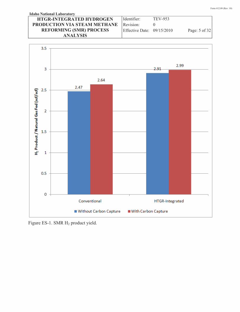
� Integration of nuclear heat can reduce the amount of natural gas required to produce a given quantity of hydrogen. If CC is not included in the design, these results indicate that natural gas consumption can be reduced by 15.3%. For a design that incorporates CC, the reduction is 11.6%. These results are reflected in the H2 product yield, as shown in ES-1.
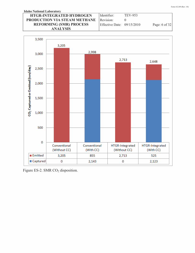
� CO2 emissions are reduced as a result of integrating nuclear heat. If CC is not included in the design, nuclear integration results in a 15.4% reduction in CO2 emissions. For a design that incorporates CC, the CO2 emissions reduction is 38.6%. CO2 disposition for each case is shown graphically in ES-2.
� The requirements to integrate HTGR technology with SMR for hydrogen production are quite modest—¼ or less of a 600-MWt reactor would be sufficient to support a world-scale single-train hydrogen plant (130 MMSCFD). Large
Form 412.09 (Rev. 10)
Idaho National Laboratory HTGR-INTEGRATED HYDROGEN
PRODUCTION VIA STEAM METHANE REFORMING (SMR) PROCESS
ANALYSIS
Identifier: Revision: Effective Date:
TEV-953 0 09/15/2010 Page: 4 of 32
industrial processes may require multiple trains of this size to meet their hydrogen demand, therefore justifying construction of one or more HTGRs.
Based on the results of this study, several follow-on activities are recommended. The most significant of these recommendations are listed below.
� An economic analysis should be performed using the modeling results from this study as input. It is believed that such an analysis would further quantify the benefits of integrating HTGR heat with SMR technology for hydrogen production.
� It is likely that process results for the HTGR-integrated case could be improved if the HTGR temperature could be increased beyond 750°C (1,382°F). Hence, a study to quantify the performance improvement is recommended. Observations from this study indicate that CC should be included in the baseline configuration for the temperature sensitivity study.
� Additional work is warranted to scope out initial equipment design and further assess the feasibility of a HTGR-integrated SMR. As indicated in this report, the mode of heat transfer would shift from radiation in a conventional design to convection in a HTGR-integrated design.
Form 412.09 (Rev. 10)
Idaho National Laboratory HTGR-INTEGRATED HYDROGEN
PRODUCTION VIA STEAM METHANE REFORMING (SMR) PROCESS
ANALYSIS
Identifier: Revision: Effective Date:
TEV-953 0 09/15/2010 Page: 5 of 32
Figure ES-1. SMR H2 product yield.
Form 412.09 (Rev. 10)
Idaho National Laboratory HTGR-INTEGRATED HYDROGEN
PRODUCTION VIA STEAM METHANE REFORMING (SMR) PROCESS
ANALYSIS
Identifier: Revision: Effective Date:
TEV-953 0 09/15/2010 Page: 6 of 32
Figure ES-2. SMR CO2 disposition.

Form 412.09 (Rev. 10)
Idaho National Laboratory HTGR-INTEGRATED HYDROGEN
PRODUCTION VIA STEAM METHANE REFORMING (SMR) PROCESS
ANALYSIS
Identifier: Revision: Effective Date:
TEV-953 0 09/15/2010 Page: 7 of 32
CONTENTS
EXECUTIVE SUMMARY .............................................................................................................3�
ACRONYMS AND NOMENCLATURE .......................................................................................8�
1.� INTRODUCTION ...............................................................................................................9�
2.� PROCESS DESCRIPTION ...............................................................................................10�
2.1� Conventional Production of Hydrogen via SMR ...................................................10�
2.2� Nuclear-Integration Study Considerations .............................................................14�
3.� PROCESS MODELING OVERVIEW..............................................................................15�
3.1� Conventional SMR Process (Without CC) ............................................................16�
3.2� Conventional SMR Process (With CC) .................................................................19�
3.3� HTGR-integrated SMR Process (Without CC)......................................................21�
3.4� HTGR-integrated SMR Process (With CC) ...........................................................23�
4.� PROCESS MODELING RESULTS AND OBSERVATIONS ........................................25�
5.� FUTURE WORK AND RECOMMENDATIONS ...........................................................31�
6.� REFERENCES ..................................................................................................................31�
7.� APPENDIXES ...................................................................................................................32�

Form 412.09 (Rev. 10)
Idaho National Laboratory HTGR-INTEGRATED HYDROGEN
PRODUCTION VIA STEAM METHANE REFORMING (SMR) PROCESS
ANALYSIS
Identifier: Revision: Effective Date:
TEV-953 0 09/15/2010 Page: 8 of 32
ACRONYMS AND NOMENCLATURE
CC carbon capture
DOE Department of Energy
GHG greenhouse gases
HHV higher heating value
HTGR High Temperature Gas-cooled Reactor
HTSE high-temperature steam electrolysis
INL Idaho National Laboratory
MMBTU 1,000,000 British thermal units
MMSCF 1,000,000 standard cubic feet
NGNP Next Generation Nuclear Plant
PSA pressure swing absorption
ROT reactor outlet temperature
SMR steam methane reformer
TEV technical evaluation
Form 412.09 (Rev. 10)
Idaho National Laboratory HTGR-INTEGRATED HYDROGEN
PRODUCTION VIA STEAM METHANE REFORMING (SMR) PROCESS
ANALYSIS
Identifier: Revision: Effective Date:
TEV-953 0 09/15/2010 Page: 9 of 32
1. INTRODUCTION
This technical evaluation (TEV) has been prepared as part of a study for the Next Generation Nuclear Plant (NGNP) Project to evaluate integration of High Temperature Gas-cooled Reactor (HTGR) technology with conventional chemical processes. The NGNP Project is being conducted under U.S. Department of Energy (DOE) direction to meet a national strategic need identified in the 2005 Energy Policy Act to promote reliance on safe, clean, economic nuclear energy and to establish a greenhouse-gas (GHG)-free technology for the production of hydrogen. The NGNP represents an integration of high-temperature reactor technology with advanced hydrogen, electricity, and process heat production capabilities, thereby meeting the mission need identified by DOE. The strategic goal of the NGNP Project is to broaden the environmental and economic benefits of nuclear energy in the U.S. economy by demonstrating its applicability to market sectors not being served by light water reactors.
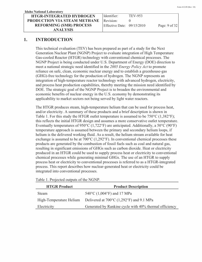
The HTGR produces steam, high-temperature helium that can be used for process heat, and/or electricity. A summary of these products and a brief description is shown in Table 1. For this study the HTGR outlet temperature is assumed to be 750°C (1,382°F); this reflects the initial HTGR design and assumes a more conservative outlet temperature. Eventually temperatures of 950°C (1,722°F) are anticipated. Additionally, a 50°C (90°F) temperature approach is assumed between the primary and secondary helium loops, if helium is the delivered working fluid. As a result, the helium stream available for heat exchange is assumed to be at 700°C (1,292°F). In conventional chemical processes these products are generated by the combustion of fossil fuels such as coal and natural gas, resulting in significant emissions of GHGs such as carbon dioxide. Heat or electricity produced in an HTGR could be used to supply process heat or electricity to conventional chemical processes while generating minimal GHGs. The use of an HTGR to supply process heat or electricity to conventional processes is referred to as a HTGR-integrated process. This report describes how nuclear-generated heat or electricity could be integrated into conventional processes.
Table 1. Projected outputs of the NGNP.
HTGR Product Product Description
Steam 540°C (1,004°F) and 17 MPa
High-Temperature Helium Delivered at 700°C (1,292°F) and 9.1 MPa
Electricity Generated by Rankine cycle with 40% thermal efficiency
Form 412.09 (Rev. 10)
Idaho National Laboratory HTGR-INTEGRATED HYDROGEN
PRODUCTION VIA STEAM METHANE REFORMING (SMR) PROCESS
ANALYSIS
Identifier: Revision: Effective Date:
TEV-953 0 09/15/2010 Page: 10 of 32
This TEV addresses potential integration opportunities for hydrogen production via steam methane reforming (SMR) of natural gas. More specifically, this TEV considers only integration of nuclear heat and electricity into the process—hydrogen production via high-temperature steam electrolysis (HTSE) is not addressed.a The HTGR would produce electricity and heat, and would be located near the SMR facility. Details of the specific cases considered are described in Sections 2 and 3 of this report. A separate study should be conducted to assess the optimal siting of the HTGR with respect to the SMR facilities, balancing safety concerns associated with separation distance and heat losses associated with transporting high-temperature heat long distances.
The Advanced Process and Decision Systems Department at Idaho National Laboratory (INL) has spent several years developing detailed process simulations of chemical processes, typically utilizing fossil fuels such as coal, biomass, or natural gas as the feedstock. These simulations have been developed using Aspen Plus, a state-of-the-art, steady-state chemical process simulator (Aspen 2006). This study makes extensive use of these models and the modeling capability at INL to evaluate the integration of HTGR technology with commercial hydrogen production methods.
This TEV assumes familiarity with Aspen Plus; hence, a detailed explanation of the software capabilities, thermodynamic packages, unit operation models, and solver routines is beyond the scope of this study.
This TEV first presents a general discussion of conventional steam methane reforming technologies used to produce hydrogen. Next, the specific processes selected for modeling are presented. A description of each process model is then provided. Finally, the results of the process modeling are discussed with emphasis placed on the impact of the HTGR integration.
2. PROCESS DESCRIPTION
2.1 Conventional Production of Hydrogen via SMR
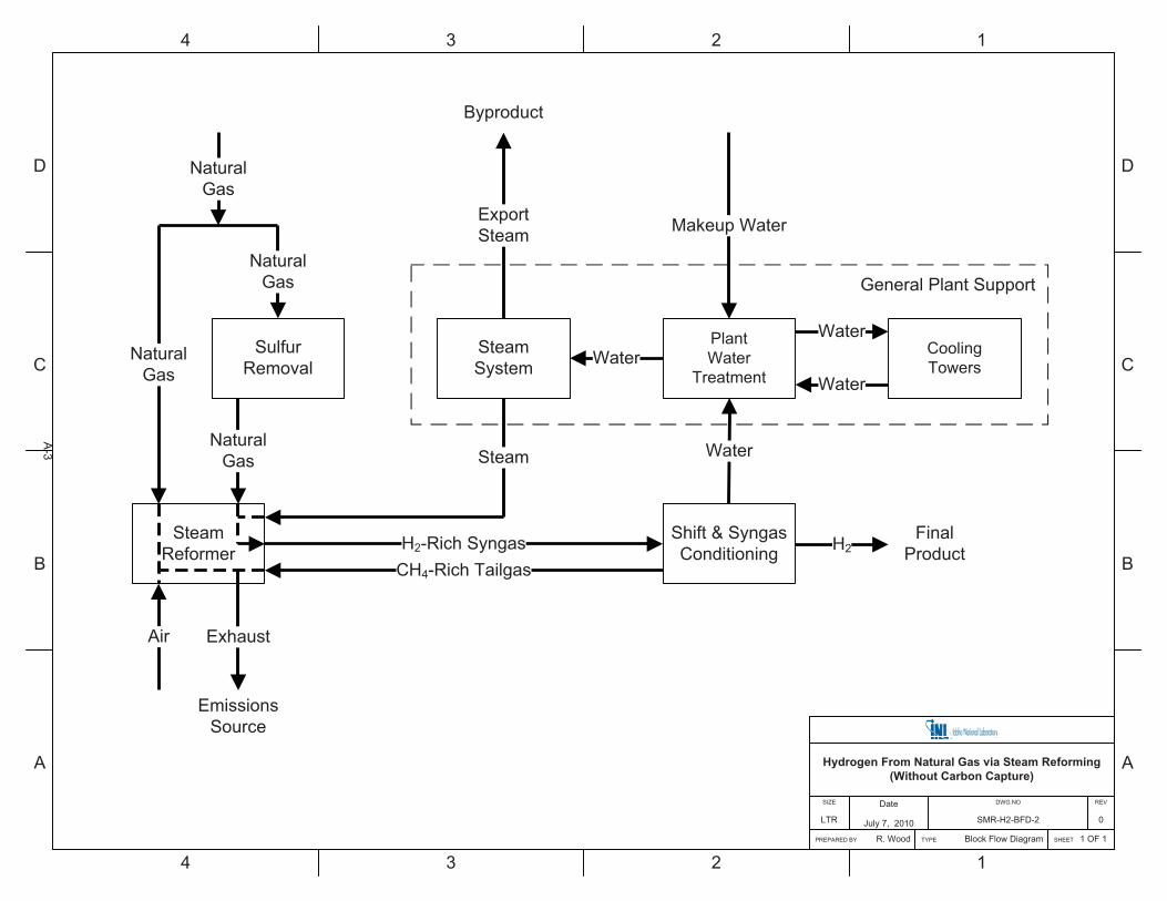
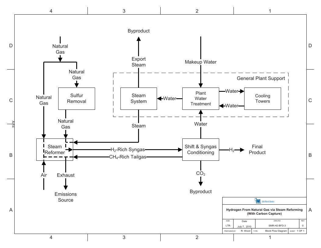
A block flow diagram for a typical hydrogen production plant is shown in Figure 1. A majority of the natural gas fed to the plant is first desulfurized. The desulfurized natural gas is mixed with steam and reformed in catalyst-filled tubes via the following endothermic reactions to produce hydrogen:
COHOHCH ��� 224 3 (1)
2224 42 COHOHCH ��� (2)
a. HTGR-integrated hydrogen production using HTSE has previously been addressed in TEV-693,
“Nuclear-Integrated Hydrogen Production Analysis.”

Form 412.09 (Rev. 10)
Idaho National Laboratory HTGR-INTEGRATED HYDROGEN
PRODUCTION VIA STEAM METHANE REFORMING (SMR) PROCESS
ANALYSIS
Identifier: Revision: Effective Date:
TEV-953 0 09/15/2010 Page: 11 of 32
Reformer temperatures between 800 and 870�C (1,472–1,598�F) are typical (Baade 2001), although lower temperatures (~760�C [1,400�F]) can be used to reduce the metallurgical requirements of the reforming tubes (Elshout 2010). Conversion of methane to hydrogen is improved by operating at higher temperatures. Many modern designs operate near the upper end of the temperature range, typically 860–880�C (1,580–1,616�F) to improve conversion (Uhde 2009).
Figure 1. Typical block flow diagram for hydrogen production using SMR.
Adequate steam must also be fed to the reformer to prevent laydown of coke on the reforming catalyst. A steam-to-carbon molar ratio of three is typical for a natural gas feed consisting primarily of methane, but ratios as high as five have been used commercially to improve conversion in the reformer.
Due to the endothermic nature of the reforming reactions, heat must be supplied to the reformer. This is accomplished by firing natural gas to heat the reforming tubes. The amount of fresh natural gas that must be fired can be minimized by supplementing the burner with methane-rich tailgas that has been separated from
Form 412.09 (Rev. 10)
Idaho National Laboratory HTGR-INTEGRATED HYDROGEN
PRODUCTION VIA STEAM METHANE REFORMING (SMR) PROCESS
ANALYSIS
Identifier: Revision: Effective Date:
TEV-953 0 09/15/2010 Page: 12 of 32
the hydrogen product. Hence, there is a trade-off to be made in the design of a hydrogen plant:
1. Lower reformer temperature – A lower temperature reduces the metallurgical requirements for the reforming tubes. However, because a significant fraction of methane is unconverted through the reformer, more extensive separation is required and the overall size of the process equipment is somewhat increased.
2. Higher reformer temperature – A higher temperature increases the metallurgical requirements for the reforming tubes. However, methane conversion is higher resulting in a corresponding reduction in the size of the process equipment. Additionally, the separation requirements are somewhat reduced due to the lower methane concentration in the raw hydrogen product.
Another consideration in the design of a hydrogen plant is the desired amount of steam export. For a stand-alone hydrogen plant, it may be desirable to minimize steam export from the plant. However, if the hydrogen plant is located adjacent to another chemical process that requires process steam, it may be desirable to design the hydrogen plant for increased steam export.
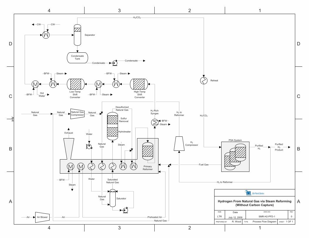
As shown in Figure 1, the syngas produced in the reformer must be shifted and conditioned to produce a purified hydrogen product. The first step in purifying the reformed syngas involves conversion of carbon monoxide formed via Reaction 1 to hydrogen. This is accomplished using shift conversion and serves to maximize hydrogen production from the plant. Shift conversion is accomplished catalytically via the following exothermic reversible reaction:
222 COHOHCO ��� (3)
This reaction proceeds faster at a higher temperature, but lower equilibrium CO concentration (and hence, maximum H2 production) is favored at a lower temperature. Hence, a typical shift conversion arrangement consists of two catalytic beds in series with interstage heat exchange.b The first bed, or high-temperature shift reactor, typically operates with an inlet temperature between 320 and 350�C (608–662�F). Due to the exothermic nature of the shift reaction, this temperature rises to approximately 420�C (788�F) at the outlet of the high-temperature shift reactor. The majority of the CO conversion is accomplished in the first stage where faster reaction kinetics are favorable due to the elevated operating temperature. This minimizes the size of the equipment.
b See the process flow diagram presented in Appendix A for details of the two-bed shift conversion reactors and heat
recuperation.
Form 412.09 (Rev. 10)
Idaho National Laboratory HTGR-INTEGRATED HYDROGEN
PRODUCTION VIA STEAM METHANE REFORMING (SMR) PROCESS
ANALYSIS
Identifier: Revision: Effective Date:
TEV-953 0 09/15/2010 Page: 13 of 32
Effluent from the first stage is cooled to approximately 200�C (392�F) prior to introduction to the second (low-temperature) shift converter. This stage converts a majority of the remaining CO to CO2, thus maximizing hydrogen production by taking advantage of the favorable equilibrium conditions at the lower temperature.
Following shift conversion, there are several options for CO2 removal and final purification of the hydrogen product. Two factors determine which option is selected: (1) the required purity of the hydrogen product, and (2) the need to sequester CO2.
When low-purity hydrogen (<99%) is the desired product, two purifications steps are typically utilized: CO2 removal and methanation. CO2 is scrubbed out using any number of commercial solvents such as hot potassium carbonate, amines (such as MEA or MDEA), Selexol™, Rectisol™, or Sulfinol™. Once the bulk CO2 has been absorbed from the hydrogen product, residual CO and CO2 are removed in a methanation reactor, which converts carbon oxides to methane via the following reactions (Kohl 1997):
OHCHHCO 2423 ��� (4)
OHCHHCO 2422 24 ��� (5)
The primary impurity remaining in the hydrogen product is methane—a small amount as a result of methanation, and a larger amount as a result of incomplete methane conversion in the steam reformer. A typical hydrogen product is 98.2% H2 and 1.8% CH4, but may be as low as 92–95% H2 (Baade 2001). Obviously the final purity is very closely tied to methane conversion in the reformer.
When high purity hydrogen (>99%) is the desired product, a single purification step is typically utilized: pressure swing adsorption (PSA). In years past, cryogenic separation was utilized, but this option has essentially been replaced by PSA in newer designs. The basic principle of PSA is that larger molecules and other light hydrocarbons can be selectively adsorbed on high surface area materials such as molecular sieves. Hydrogen has a week affinity for adsorption. In a PSA system, a bed is operated under a pressurization–depressurization cycle. Multiple beds are typically used in order to provide a continuous flow of hydrogen even when some beds are in the depressurization (or desorption) cycle. Hydrogen recovery using a PSA system is typically 70–90%, with the ability to produce very pure hydrogen (99.999%). Note that in a typical PSA system, the desorbed reject gas used as fuel gas in the reformer typically contains a large fraction of CO2 as well as combustible CO, CH4, and H2. Hence, the fuel gas can have a relatively low heating value. One advantage of the PSA system is that final product purity is decoupled from methane conversion in the reformer.
Form 412.09 (Rev. 10)
Idaho National Laboratory HTGR-INTEGRATED HYDROGEN
PRODUCTION VIA STEAM METHANE REFORMING (SMR) PROCESS
ANALYSIS
Identifier: Revision: Effective Date:
TEV-953 0 09/15/2010 Page: 14 of 32
When both a high-purity hydrogen product and carbon capture (CC) are required, two purification steps are typically implemented: CO2 removal and final H2 purification. As with the low hydrogen purity option described above, CO2 can be absorbed using any number of commercial solvents. The hydrogen stream is further purified using PSA to remove methane and any traces of CO, CO2, or other impurities. This results in a very pure hydrogen product stream, a sequestration-ready CO2 stream, and a relatively high heating value fuel gas stream for use in the reformer.
Very few (if any) hydrogen plants currently sequester CO2. The above option (CO2 absorption followed by PSA for final H2 purification) simply represents a combination of two well-proven technologies in the hydrogen manufacturing industry (i.e., low risk). A less-proven but potentially desirable option could be to use a specially tuned PSA system to simultaneously produce purified hydrogen, purified CO2, and a high heating value fuel gas. Air Products has experimented with such a system at the pilot scale. Results indicated that the process can produce ultra-pure hydrogen (99.999%) at a recovery of 86–88% simultaneously with relatively pure carbon dioxide (99.4%) at a recovery in excess of 90% (Kohl 1997).
2.2 Nuclear-Integration Study Considerations
INL studies conducted during the last year have investigated hydrogen production via SMR for specific applications: Fischer-Tropsch synthesis for diesel fuel production (INL 2010a), methanol production with subsequent conversion to gasoline (INL 2010b), and ammonia production (INL 2010c). For each of these applications, reforming was tailored to produce the optimal synthesis gas. For this study, however, hydrogen is the final product rather than an intermediate product. Hence, to provide maximum flexibility for product use, a high-purity hydrogen plant configuration was selected for evaluation.
It is not standard practice to capture and sequester CO2 as part of the H2 manufacturing process. However, as environmental policy develops in regard to GHG emissions, it is conceivable that future H2 plants may be required to reduce CO2 emissions. Hence, for this study both CC and non-CC options were evaluated.
Another nuclear-integration issue that needed to be addressed in this study was the slight temperature mismatch between what can be supplied by a first-generation HTGR (700�C [1,292�F]) versus the optimal steam methane reformer operating temperature (760–880�C [1,400–1,616�F]). This discrepancy will be eliminated as future HTGR designs supply higher temperature heat (up to 900�C [1,652�F]). However, because this study assumes the HTGR can provide only 700�C (1,292�F) heat, some process modifications were required in order to
Form 412.09 (Rev. 10)
Idaho National Laboratory HTGR-INTEGRATED HYDROGEN
PRODUCTION VIA STEAM METHANE REFORMING (SMR) PROCESS
ANALYSIS
Identifier: Revision: Effective Date:
TEV-953 0 09/15/2010 Page: 15 of 32
utilize the available heat. The approach taken in this study was to separate the primary reformer into two zones or stages. In the first stage, nuclear heat replaces gas firing as the heat source. The partially reformed gas exiting the first stage is then routed to the second reformer stage. In this stage, additional heat is supplied by firing fuel gas to complete the reforming process.
3. PROCESS MODELING OVERVIEW
Plant models for hydrogen production via SMR were developed using Aspen Plus (Aspen 2006). Because of the size and complexity of the process modeled, the simulation was constructed using “hierarchy” blocks. A hierarchy block is a method for nesting one simulation within another simulation. In this manner, submodels for each major plant section were constructed separately and then combined to represent the entire process.
Significant emphasis in the models has been placed on heat integration between different parts of the plant. To facilitate energy tracking, Aspen’s “utility” blocks were used extensively. Utility blocks tracked electricity, steam, and cooling water usage. Aspen Plus Version 2006 (Build 20.0.3.4127), run under Windows XP SP3 on computer ID 410530 (model MacPro2,1), was used for all modeling calculations.
The original models for the fossil portion of the plant were developed using English units, which is common industrial practice in the United States. Nuclear plants typically use metric units; hence, this report contains both English and metric units depending on the context of the information presented.
Four cases were originally identified for modeling, including flowsheets both with and without CC:
� Conventional SMR process without CC
� Conventional SMR process with CC
� HTGR-integrated SMR process without CC
� HTGR-integrated SMR process with CC.
For all cases, natural gas composition was taken from data published by Northwest Gas Association. Net capacity for the plant was set at 130 million scfd of hydrogen (29,000 lb/hr), which corresponds with the size of the largest single train hydrogen plant currently in operation in Europe.
For the Aspen models described in this analysis, a rigorous submodel of the nuclear power cycle has not yet been integrated. For this analysis, it is assumed that the reactor can provide hot helium for integration with the hydrogen plant as well as a Rankine cycle to generate electricity. A portion of the electricity generated by the HTGR plant is used to supply the needs of the hydrogen plant; the balance can be sold as a byproduct. Results for the nuclear power cycle were calculated separately using the UNISIM modeling
Form 412.09 (Rev. 10)
Idaho National Laboratory HTGR-INTEGRATED HYDROGEN
PRODUCTION VIA STEAM METHANE REFORMING (SMR) PROCESS
ANALYSIS
Identifier: Revision: Effective Date:
TEV-953 0 09/15/2010 Page: 16 of 32
package. Water consumption for the HTGR and associated power cycle has not been included, as a detailed water balance for the HTGR has not been completed at this time.
A general model description for each case is presented below. Natural gas feed rate in each model was adjusted to achieve the desired net capacity for the plant of 130 million scfd of hydrogen, which matches the present capacity of a world-scale single-train hydrogen plant.
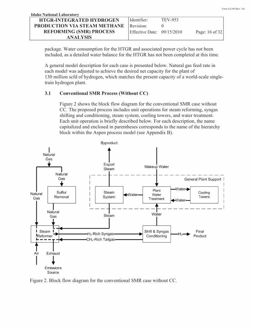
3.1 Conventional SMR Process (Without CC)
Figure 2 shows the block flow diagram for the conventional SMR case without CC. The proposed process includes unit operations for steam reforming, syngas shifting and conditioning, steam system, cooling towers, and water treatment. Each unit operation is briefly described below. For each description, the name capitalized and enclosed in parentheses corresponds to the name of the hierarchy block within the Aspen process model (see Appendix B).
Figure 2. Block flow diagram for the conventional SMR case without CC.
Form 412.09 (Rev. 10)
Idaho National Laboratory HTGR-INTEGRATED HYDROGEN
PRODUCTION VIA STEAM METHANE REFORMING (SMR) PROCESS
ANALYSIS
Identifier: Revision: Effective Date:
TEV-953 0 09/15/2010 Page: 17 of 32
� Sulfur Removal, Steam Reformer (REFORMER) – For this study, a reformer temperature of 871°C (1,600°F) was selected to balance high methane conversion with reasonable reformer tube life. The steam-to-carbon inlet molar ratio was set at 3.0 in order to avoid carbon deposition on the reforming catalyst (Elshout 2010).
Natural gas is split into two streams. Of the total natural gas flow, 15.1% is burned to provide heat for the primary reformer. The remaining 84.9% of the natural gas flow is compressed to 460 psia and mixed with a small amount of hydrogen to achieve a concentration of 2 mol% H2. The addition of a small amount of hydrogen is required to convert any sulfur in the natural gas to a chemical form that can be removed in the sulfur removal bed. The natural gas is then preheated to 221°C (430°F) and saturated with hot water. After saturation, the gas is further heated to 400°C (752°F) prior to hydrotreating to convert sulfur compounds to H2S. Sulfur is then removed from the gas using a bed of zinc oxide. The desulfurized natural gas is then mixed with steam to achieve the desired steam-to-carbon molar ratio of 3.0. The resulting natural gas/steam mixture is then preheated to 700°C (1,292�F) prior to introduction to the reformer. A preformer is not included in this flowsheet, although it could be considered due to the relatively high preheat temperature.
The natural gas/steam mixture is fed to the primary reformer where methane is converted over a catalyst to CO, H2, and CO2. Using a Gibbs free energy minimization routine, methane conversion in the reformer is predicted to be 78.1% based on the specified conditions. A separate feed of the natural gas is mixed with fuel gas and burned to provide heat for the endothermic reforming reactions. The hot offgas from the reformer is exchanged with inlet natural gas, syngas, water, and steam to provide preheat for these streams. In addition, the hot offgas from the reformer is used to preheat combustion air as well as raising 600 psig and 60 psig steam.
The effluent syngas from the primary reformer is cooled by exchange with boiler feed water to raise 600 psig steam. The resulting syngas has a H2/CO ratio of 5.2 and contains 34.2 mol% H2O, 5.3 mol% CO2, and 3.5 mol% CH4.
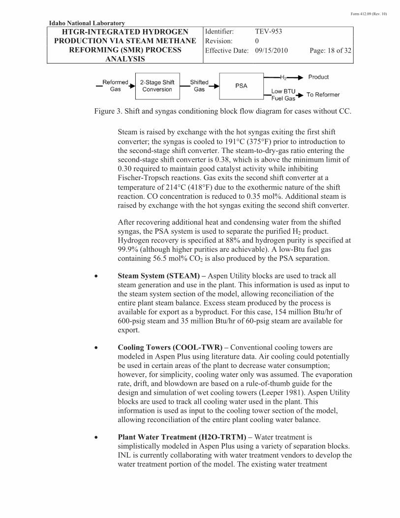
� Shift & Syngas Conditioning (GAS-CLN) – Figure 3 shows the shift and syngas conditioning scenario modeled for this case. Reformed gas is fed to the first shift converter at a temperature of 335�C (635�F) with a steam-to-dry-gas ratio of 0.52. Gas exits the first shift converter at a temperature of 409�C (769�F) due to the exothermic nature of the shift reaction. CO concentration is reduced to 3.2 mol%.
Form 412.09 (Rev. 10)
Idaho National Laboratory HTGR-INTEGRATED HYDROGEN
PRODUCTION VIA STEAM METHANE REFORMING (SMR) PROCESS
ANALYSIS
Identifier: Revision: Effective Date:
TEV-953 0 09/15/2010 Page: 18 of 32
Figure 3. Shift and syngas conditioning block flow diagram for cases without CC.
Steam is raised by exchange with the hot syngas exiting the first shift converter; the syngas is cooled to 191�C (375�F) prior to introduction to the second-stage shift converter. The steam-to-dry-gas ratio entering the second-stage shift converter is 0.38, which is above the minimum limit of 0.30 required to maintain good catalyst activity while inhibiting Fischer-Tropsch reactions. Gas exits the second shift converter at a temperature of 214�C (418�F) due to the exothermic nature of the shift reaction. CO concentration is reduced to 0.35 mol%. Additional steam is raised by exchange with the hot syngas exiting the second shift converter.
After recovering additional heat and condensing water from the shifted syngas, the PSA system is used to separate the purified H2 product. Hydrogen recovery is specified at 88% and hydrogen purity is specified at 99.9% (although higher purities are achievable). A low-Btu fuel gas containing 56.5 mol% CO2 is also produced by the PSA separation.
� Steam System (STEAM) – Aspen Utility blocks are used to track all steam generation and use in the plant. This information is used as input to the steam system section of the model, allowing reconciliation of the entire plant steam balance. Excess steam produced by the process is available for export as a byproduct. For this case, 154 million Btu/hr of 600-psig steam and 35 million Btu/hr of 60-psig steam are available for export.
� Cooling Towers (COOL-TWR) – Conventional cooling towers are modeled in Aspen Plus using literature data. Air cooling could potentially be used in certain areas of the plant to decrease water consumption; however, for simplicity, cooling water only was assumed. The evaporation rate, drift, and blowdown are based on a rule-of-thumb guide for the design and simulation of wet cooling towers (Leeper 1981). Aspen Utility blocks are used to track all cooling water used in the plant. This information is used as input to the cooling tower section of the model, allowing reconciliation of the entire plant cooling water balance.
� Plant Water Treatment (H2O-TRTM) – Water treatment is simplistically modeled in Aspen Plus using a variety of separation blocks. INL is currently collaborating with water treatment vendors to develop the water treatment portion of the model. The existing water treatment

Form 412.09 (Rev. 10)
Idaho National Laboratory HTGR-INTEGRATED HYDROGEN
PRODUCTION VIA STEAM METHANE REFORMING (SMR) PROCESS
ANALYSIS
Identifier: Revision: Effective Date:
TEV-953 0 09/15/2010 Page: 19 of 32
scenario is a place holder and will be revised as information is received from the water treatment vendors. Hence, it is anticipated that energy consumption for the water treatment portion of the plant could change considerably based on water treatment vendor feedback. Aspen Transfer blocks are used to reconcile water in-and-out flows from various parts of the plant, allowing reconciliation of the entire plant water balance.
3.2 Conventional SMR Process (With CC)
Figure 4 shows the block flow diagram for the conventional SMR case with CC. The proposed process includes unit operations for steam reforming, syngas shifting and conditioning, steam system, cooling towers, and water treatment. Each unit operation is briefly described below. For each description, the name capitalized and enclosed in parentheses corresponds to the name of the hierarchy block within the Aspen process model (see Appendix C). Because many of the unit operations remain unchanged from the conventional SMR case without CC, emphasis is placed on differences in configuration between the two cases.
Figure 4. Block flow diagram for the conventional SMR case with CC.
Form 412.09 (Rev. 10)
Idaho National Laboratory HTGR-INTEGRATED HYDROGEN
PRODUCTION VIA STEAM METHANE REFORMING (SMR) PROCESS
ANALYSIS
Identifier: Revision: Effective Date:
TEV-953 0 09/15/2010 Page: 20 of 32
� Sulfur Removal, Steam Reformer (REFORMER) – Steam reforming configuration and conditions in the SMR case with CC are nearly identical to those used in the conventional SMR case without CC. The primary difference is that the higher Btu content of the fuel gas in this case results in a lower demand for fresh natural gas to fire the reformer. The fraction of the total natural gas feed used for firing the reformer is reduced from 15.1% in the non-CC case to 9.0% for the CC case. Other key operating parameters are identical between the cases.
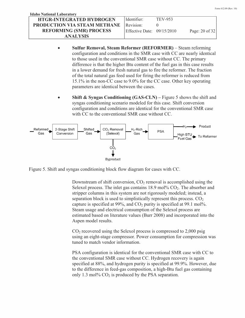
� Shift & Syngas Conditioning (GAS-CLN) – Figure 5 shows the shift and syngas conditioning scenario modeled for this case. Shift conversion configuration and conditions are identical for the conventional SMR case with CC to the conventional SMR case without CC.
Figure 5. Shift and syngas conditioning block flow diagram for cases with CC.
Downstream of shift conversion, CO2 removal is accomplished using the Selexol process. The inlet gas contains 18.9 mol% CO2. The absorber and stripper columns in this system are not rigorously modeled; instead, a separation block is used to simplistically represent this process. CO2 capture is specified at 99%, and CO2 purity is specified at 99.1 mol%. Steam usage and electrical consumption of the Selexol process are estimated based on literature values (Burr 2008) and incorporated into the Aspen model results.
CO2 recovered using the Selexol process is compressed to 2,000 psig using an eight-stage compressor. Power consumption for compression was tuned to match vendor information.
PSA configuration is identical for the conventional SMR case with CC to the conventional SMR case without CC. Hydrogen recovery is again specified at 88%, and hydrogen purity is specified at 99.9%. However, due to the difference in feed-gas composition, a high-Btu fuel gas containing only 1.3 mol% CO2 is produced by the PSA separation.
Form 412.09 (Rev. 10)
Idaho National Laboratory HTGR-INTEGRATED HYDROGEN
PRODUCTION VIA STEAM METHANE REFORMING (SMR) PROCESS
ANALYSIS
Identifier: Revision: Effective Date:
TEV-953 0 09/15/2010 Page: 21 of 32
� Steam System (STEAM) – The steam system in the conventional SMR case with CC is identical to that in the conventional SMR case without CC. For this case, 24 million Btu/hr of 600-psig steam is available for export.
� Cooling Towers (COOL-TWR) – The cooling towers in the conventional SMR case with CC are identical to those in the conventional SMR case without CC.
� Plant Water Treatment (H2O-TRTM) – The water treatment system in the conventional SMR case with CC is identical to that in the conventional SMR case without CC.
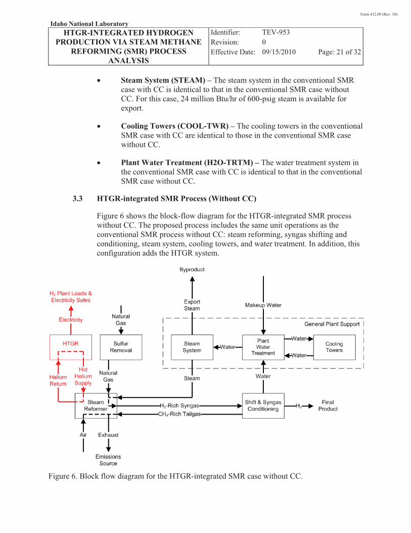
3.3 HTGR-integrated SMR Process (Without CC)
Figure 6 shows the block-flow diagram for the HTGR-integrated SMR process without CC. The proposed process includes the same unit operations as the conventional SMR process without CC: steam reforming, syngas shifting and conditioning, steam system, cooling towers, and water treatment. In addition, this configuration adds the HTGR system.
Figure 6. Block flow diagram for the HTGR-integrated SMR case without CC.
Form 412.09 (Rev. 10)
Idaho National Laboratory HTGR-INTEGRATED HYDROGEN
PRODUCTION VIA STEAM METHANE REFORMING (SMR) PROCESS
ANALYSIS
Identifier: Revision: Effective Date:
TEV-953 0 09/15/2010 Page: 22 of 32
Each unit operation is briefly described below. For each description, the name capitalized and enclosed in parentheses corresponds to the name of the hierarchy block within the Aspen process model (see Appendix D). Because many of the unit operations remain unchanged from the conventional SMR case without CC, emphasis is placed on differences in configuration between the two cases.
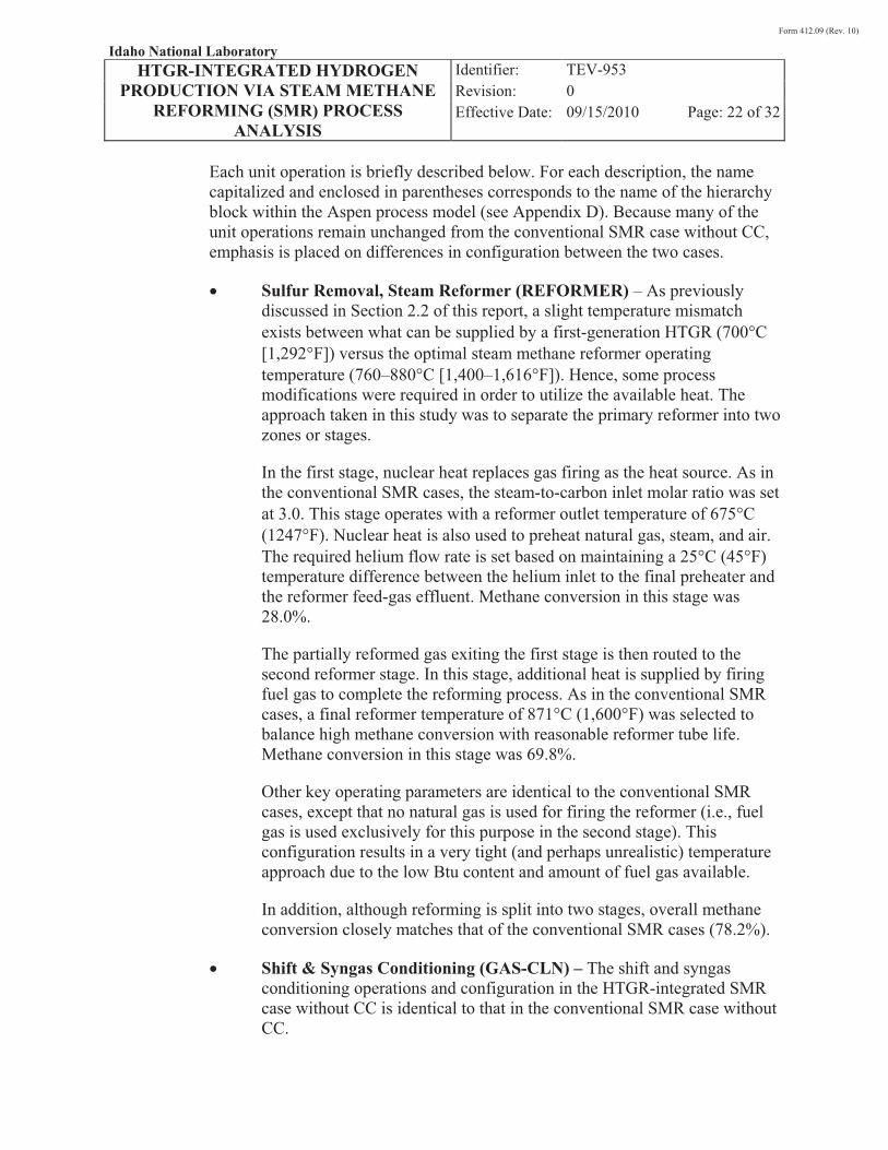
� Sulfur Removal, Steam Reformer (REFORMER) – As previously discussed in Section 2.2 of this report, a slight temperature mismatch exists between what can be supplied by a first-generation HTGR (700�C [1,292�F]) versus the optimal steam methane reformer operating temperature (760–880�C [1,400–1,616�F]). Hence, some process modifications were required in order to utilize the available heat. The approach taken in this study was to separate the primary reformer into two zones or stages.
In the first stage, nuclear heat replaces gas firing as the heat source. As in the conventional SMR cases, the steam-to-carbon inlet molar ratio was set at 3.0. This stage operates with a reformer outlet temperature of 675�C (1247�F). Nuclear heat is also used to preheat natural gas, steam, and air. The required helium flow rate is set based on maintaining a 25�C (45�F) temperature difference between the helium inlet to the final preheater and the reformer feed-gas effluent. Methane conversion in this stage was 28.0%.
The partially reformed gas exiting the first stage is then routed to the second reformer stage. In this stage, additional heat is supplied by firing fuel gas to complete the reforming process. As in the conventional SMR cases, a final reformer temperature of 871°C (1,600°F) was selected to balance high methane conversion with reasonable reformer tube life. Methane conversion in this stage was 69.8%.
Other key operating parameters are identical to the conventional SMR cases, except that no natural gas is used for firing the reformer (i.e., fuel gas is used exclusively for this purpose in the second stage). This configuration results in a very tight (and perhaps unrealistic) temperature approach due to the low Btu content and amount of fuel gas available.
In addition, although reforming is split into two stages, overall methane conversion closely matches that of the conventional SMR cases (78.2%).
� Shift & Syngas Conditioning (GAS-CLN) – The shift and syngas conditioning operations and configuration in the HTGR-integrated SMR case without CC is identical to that in the conventional SMR case without CC.
Form 412.09 (Rev. 10)
Idaho National Laboratory HTGR-INTEGRATED HYDROGEN
PRODUCTION VIA STEAM METHANE REFORMING (SMR) PROCESS
ANALYSIS
Identifier: Revision: Effective Date:
TEV-953 0 09/15/2010 Page: 23 of 32
� Steam System (STEAM) – The steam system in the HTGR-integrated SMR case without CC is identical to that in the conventional SMR case without CC. For this case, 273 million Btu/hr of 600-psig steam and 0.4 million Btu/hr of 60-psig steam are available for export.
� Cooling Towers (COOL-TWR) – The cooling towers in the HTGR-integrated SMR case without CC are identical to those in the conventional SMR case without CC.
� Plant Water Treatment (H2O-TRTM) – The water treatment system in the HTGR-integrated SMR case without CC is identical to that in the conventional SMR case without CC.
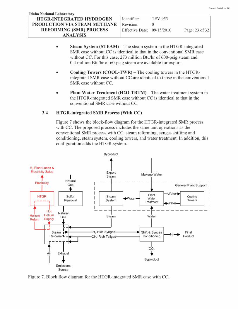
3.4 HTGR-integrated SMR Process (With CC)
Figure 7 shows the block-flow diagram for the HTGR-integrated SMR process with CC. The proposed process includes the same unit operations as the conventional SMR process with CC: steam reforming, syngas shifting and conditioning, steam system, cooling towers, and water treatment. In addition, this configuration adds the HTGR system.
Figure 7. Block flow diagram for the HTGR-integrated SMR case with CC.
Form 412.09 (Rev. 10)
Idaho National Laboratory HTGR-INTEGRATED HYDROGEN
PRODUCTION VIA STEAM METHANE REFORMING (SMR) PROCESS
ANALYSIS
Identifier: Revision: Effective Date:
TEV-953 0 09/15/2010 Page: 24 of 32
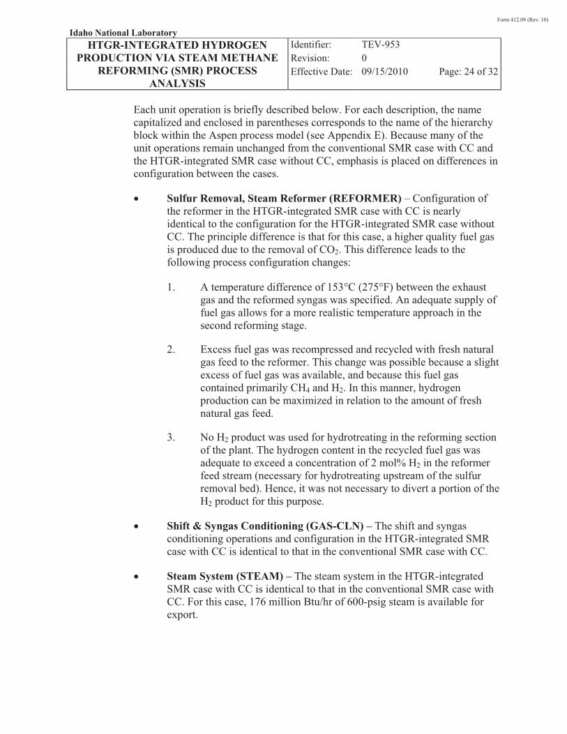
Each unit operation is briefly described below. For each description, the name capitalized and enclosed in parentheses corresponds to the name of the hierarchy block within the Aspen process model (see Appendix E). Because many of the unit operations remain unchanged from the conventional SMR case with CC and the HTGR-integrated SMR case without CC, emphasis is placed on differences in configuration between the cases.
� Sulfur Removal, Steam Reformer (REFORMER) – Configuration of the reformer in the HTGR-integrated SMR case with CC is nearly identical to the configuration for the HTGR-integrated SMR case without CC. The principle difference is that for this case, a higher quality fuel gas is produced due to the removal of CO2. This difference leads to the following process configuration changes:
1. A temperature difference of 153�C (275�F) between the exhaust gas and the reformed syngas was specified. An adequate supply of fuel gas allows for a more realistic temperature approach in the second reforming stage.
2. Excess fuel gas was recompressed and recycled with fresh natural gas feed to the reformer. This change was possible because a slight excess of fuel gas was available, and because this fuel gas contained primarily CH4 and H2. In this manner, hydrogen production can be maximized in relation to the amount of fresh natural gas feed.
3. No H2 product was used for hydrotreating in the reforming section of the plant. The hydrogen content in the recycled fuel gas was adequate to exceed a concentration of 2 mol% H2 in the reformer feed stream (necessary for hydrotreating upstream of the sulfur removal bed). Hence, it was not necessary to divert a portion of the H2 product for this purpose.
� Shift & Syngas Conditioning (GAS-CLN) – The shift and syngas conditioning operations and configuration in the HTGR-integrated SMR case with CC is identical to that in the conventional SMR case with CC.
� Steam System (STEAM) – The steam system in the HTGR-integrated SMR case with CC is identical to that in the conventional SMR case with CC. For this case, 176 million Btu/hr of 600-psig steam is available for export.
Form 412.09 (Rev. 10)
Idaho National Laboratory HTGR-INTEGRATED HYDROGEN
PRODUCTION VIA STEAM METHANE REFORMING (SMR) PROCESS
ANALYSIS
Identifier: Revision: Effective Date:
TEV-953 0 09/15/2010 Page: 25 of 32
� Cooling Towers (COOL-TWR) – The cooling towers in the HTGR-integrated SMR case with CC are identical to those in the conventional SMR case with CC.
� Plant Water Treatment (H2O-TRTM) – The water treatment system in the HTGR-integrated SMR case with CC is identical to that in the conventional SMR case with CC.
4. PROCESS MODELING RESULTS AND OBSERVATIONS
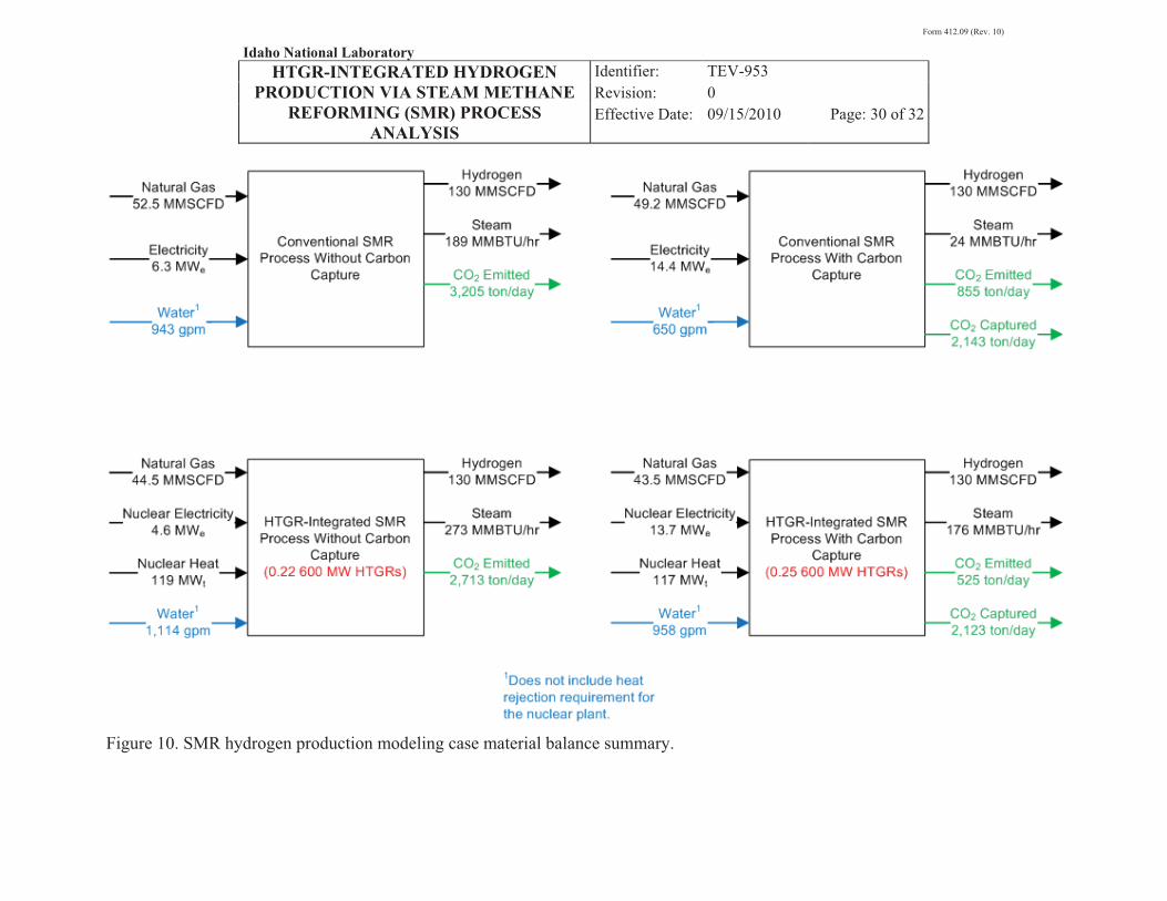
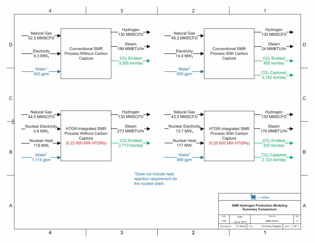
Analysis of the SMR hydrogen production process indicates that it is beneficial to replace natural gas combustion in the reformer with heat supplied by an HTGR. Key results from the modeling are presented in Table 2, while high-level material and energy balances are presented in Figure 10. For the complete modeling results, see Appendix A. Aspen stream results for all cases are presented in electronic Appendixes B, C, D, and E.
From these results, including CC in the conventional flowsheet results in an overall process efficiency penalty of 4.7%. However, this penalty is manifest as a reduction in export steam generation capability—hydrogen product yield is actually slightly better for the flowsheet that includes CC.
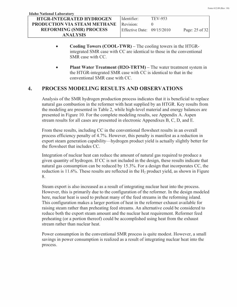
Integration of nuclear heat can reduce the amount of natural gas required to produce a given quantity of hydrogen. If CC is not included in the design, these results indicate that natural gas consumption can be reduced by 15.3%. For a design that incorporates CC, the reduction is 11.6%. These results are reflected in the H2 product yield, as shown in Figure 8.
Steam export is also increased as a result of integrating nuclear heat into the process. However, this is primarily due to the configuration of the reformer. In the design modeled here, nuclear heat is used to preheat many of the feed streams in the reforming island. This configuration makes a larger portion of heat in the reformer exhaust available for raising steam rather than preheating feed streams. An alternative could be considered to reduce both the export steam amount and the nuclear heat requirement. Reformer feed preheating (or a portion thereof) could be accomplished using heat from the exhaust stream rather than nuclear heat.
Power consumption in the conventional SMR process is quite modest. However, a small savings in power consumption is realized as a result of integrating nuclear heat into the process.
Form 412.09 (Rev. 10)
Idaho National Laboratory HTGR-INTEGRATED HYDROGEN
PRODUCTION VIA STEAM METHANE REFORMING (SMR) PROCESS
ANALYSIS
Identifier: Revision: Effective Date:
TEV-953 0 09/15/2010 Page: 26 of 32
Figure 8. SMR H2 product yield.
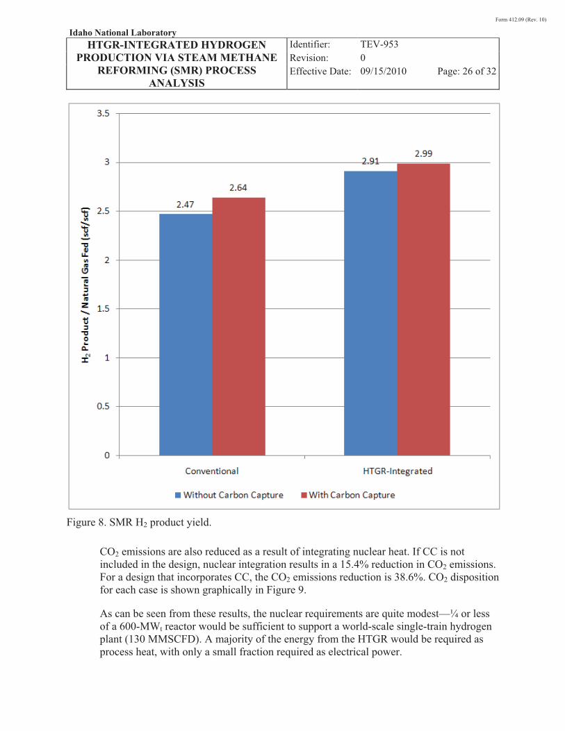
CO2 emissions are also reduced as a result of integrating nuclear heat. If CC is not included in the design, nuclear integration results in a 15.4% reduction in CO2 emissions. For a design that incorporates CC, the CO2 emissions reduction is 38.6%. CO2 disposition for each case is shown graphically in Figure 9.
As can be seen from these results, the nuclear requirements are quite modest—¼ or less of a 600-MWt reactor would be sufficient to support a world-scale single-train hydrogen plant (130 MMSCFD). A majority of the energy from the HTGR would be required as process heat, with only a small fraction required as electrical power.
Form 412.09 (Rev. 10)
Idaho National Laboratory HTGR-INTEGRATED HYDROGEN
PRODUCTION VIA STEAM METHANE REFORMING (SMR) PROCESS
ANALYSIS
Identifier: Revision: Effective Date:
TEV-953 0 09/15/2010 Page: 27 of 32
Figure 9. SMR CO2 disposition.
Figure 10 shows that integration of an HTGR increases water consumption of the plant. However, this difference is primarily attributed to the increase in steam export for the HTGR-integrated processes. The water calculations do not currently assume that condensate will be returned from exported steam.
In addition to the results summarized above and in Table 2 and Figure 10, the following observations can be made:
1. Heat transfer in a conventional reformer is largely accomplished via radiation due to the high temperatures resulting from combustion. In a HTGR-integrated scenario with a lower temperature heat source, a complete redesign of the reformer would be required to facilitate convective heat transfer rather than
Form 412.09 (Rev. 10)
Idaho National Laboratory HTGR-INTEGRATED HYDROGEN
PRODUCTION VIA STEAM METHANE REFORMING (SMR) PROCESS
ANALYSIS
Identifier: Revision: Effective Date:
TEV-953 0 09/15/2010 Page: 28 of 32
radiative heat transfer. One possible option would be to design the reformer similar to a shell and tube heat exchanger with catalyst packed in the tubes. A second option would be to design the reformer similar to a compact heat exchanger, again with catalyst packed in the tubes or coated on the tube surfaces.
2. Comparing a case without CC to a case with CC indicates that carbon removal from the fuel gas is beneficial (aside from the additional electrical power consumption required for CO2 compression). In the conventional cases, CC produced a higher quality fuel gas. This in turn ensured that the fuel gas was capable of providing the heat required for reforming (i.e., it may be necessary to supplement the fuel gas with a small amount of natural gas in the conventional case without CC). In addition, carbon removal increases the amount of hydrogen that can be produced from a given amount of natural gas, albeit at the expense of producing additional steam for export. In the HTGR-integrated cases, a similar observation can be made—carbon removal increases hydrogen production slightly at the expense of producing additional export steam.
If the PSA system alone could be used to produce both pure hydrogen and CO2, the benefits of CC could be realized without the need for additional equipment (i.e., an absorber system).
3. For the HTGR-integrated case without CC, the fuel gas contains a significant fraction of CO2. The viable options for this stream are to burn it in the reformer to provide the required heat for reformation, or to burn it to raise steam or generate power.
For the HTGR-integrated case with CC, however, the fuel gas is relatively free of CO2. Hence, a new option is available for this fuel gas stream—excess fuel gas (above and beyond what is required to supply reformation heat) can be recycled with the fresh natural gas to the reformer tubes. This option will maximize hydrogen production.
These options seem to indicate that the CC case could benefit substantially from raising the HTGR reactor outlet temperature (ROT). The increased temperature would shift more of the reforming duty from fuel gas combustion to the HTGR; hence, more fuel gas would be available for recycle to the reformer tubes to directly increase the hydrogen production rate. In contrast, for the case without CC, an increase in HTGR ROT would merely increase the amount of steam available for export.
Form 412.09 (Rev. 10)
Idaho National Laboratory HTGR-INTEGRATED HYDROGEN
PRODUCTION VIA STEAM METHANE REFORMING (SMR) PROCESS
ANALYSIS
Identifier: Revision: Effective Date:
TEV-953 0 09/15/2010 Page: 29 of 32
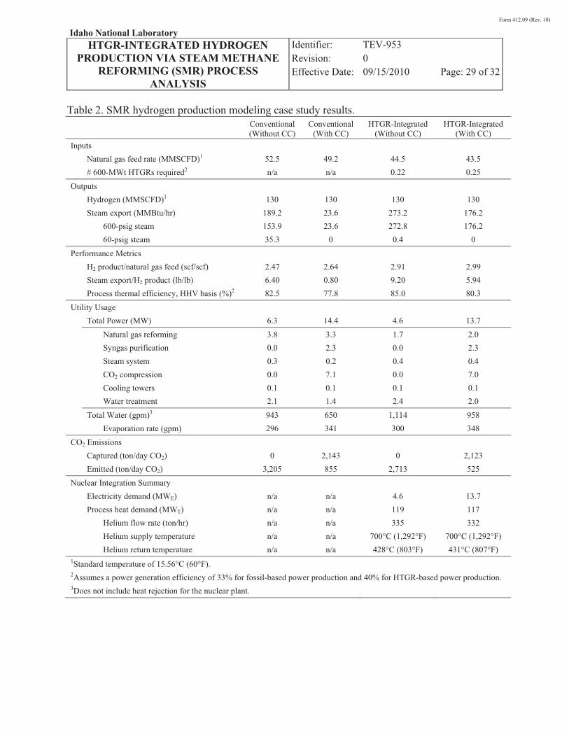
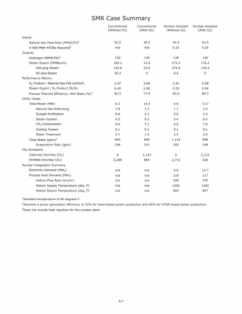
Table 2. SMR hydrogen production modeling case study results.
Conventional (Without CC)
Conventional (With CC)
HTGR-Integrated (Without CC)
HTGR-Integrated(With CC)
Inputs Natural gas feed rate (MMSCFD)1 52.5 49.2 44.5 43.5 # 600-MWt HTGRs required2 n/a n/a 0.22 0.25
Outputs Hydrogen (MMSCFD)1 130 130 130 130 Steam export (MMBtu/hr) 189.2 23.6 273.2 176.2 600-psig steam 153.9 23.6 272.8 176.2 60-psig steam 35.3 0 0.4 0
Performance Metrics H2 product/natural gas feed (scf/scf) 2.47 2.64 2.91 2.99 Steam export/H2 product (lb/lb) 6.40 0.80 9.20 5.94 Process thermal efficiency, HHV basis (%)2 82.5 77.8 85.0 80.3
Utility Usage Total Power (MW) 6.3 14.4 4.6 13.7
Natural gas reforming 3.8 3.3 1.7 2.0 Syngas purification 0.0 2.3 0.0 2.3 Steam system 0.3 0.2 0.4 0.4 CO2 compression 0.0 7.1 0.0 7.0 Cooling towers 0.1 0.1 0.1 0.1 Water treatment 2.1 1.4 2.4 2.0
Total Water (gpm)3 943 650 1,114 958 Evaporation rate (gpm) 296 341 300 348
CO2 Emissions Captured (ton/day CO2) 0 2,143 0 2,123 Emitted (ton/day CO2) 3,205 855 2,713 525
Nuclear Integration Summary Electricity demand (MWE) n/a n/a 4.6 13.7 Process heat demand (MWT) n/a n/a 119 117 Helium flow rate (ton/hr) n/a n/a 335 332 Helium supply temperature n/a n/a 700°C (1,292°F) 700°C (1,292°F) Helium return temperature n/a n/a 428°C (803°F) 431°C (807°F)
1Standard temperature of 15.56�C (60�F). 2Assumes a power generation efficiency of 33% for fossil-based power production and 40% for HTGR-based power production. 3Does not include heat rejection for the nuclear plant.
Form 412.09 (Rev. 10)
Idaho National Laboratory HTGR-INTEGRATED HYDROGEN
PRODUCTION VIA STEAM METHANE REFORMING (SMR) PROCESS
ANALYSIS
Identifier: Revision: Effective Date:
TEV-953 0 09/15/2010 Page: 30 of 32
Figure 10. SMR hydrogen production modeling case material balance summary.
Form 412.09 (Rev. 10)
Idaho National Laboratory HTGR-INTEGRATED HYDROGEN
PRODUCTION VIA STEAM METHANE REFORMING (SMR) PROCESS
ANALYSIS
Identifier: Revision: Effective Date:
TEV-953 0 09/15/2010 Page: 31 of 32
5. FUTURE WORK AND RECOMMENDATIONS
The following items should be performed in the future to refine and build upon the work summarized in this report:
� A separate study should be conducted to assess the optimal siting of the HTGR with respect to the SMR facilities, balancing safety concerns associated with separation distance and heat losses associated with transporting high-temperature heat long distances.
� A rigorous Aspen Plus submodel of the HTGR units should be developed to fully couple heat and power integration from the HTGR.
� The simplified water-treatment hierarchy should be replaced with more rigorous water-treatment models based on vendor input.
� An economic analysis should be performed using the modeling results from this study as input. It is believed that such an analysis would further quantify the benefits of integrating HTGR heat with SMR technology for hydrogen production.
� It is likely that process results for the HTGR-integrated case could be improved if the HTGR temperature could be increased beyond 750°C (1,382°F). Hence, a study to quantify the performance improvement is recommended. Observations from this study indicate that CC should be included in the baseline configuration for the temperature sensitivity study.
� Additional work is warranted to scope out initial equipment design and further assess the feasibility of a HTGR-integrated SMR. As indicated in this report, the mode of heat transfer would shift from radiation in a conventional design to convection in a HTGR-integrated design.
6. REFERENCES
Aspen Plus, Version 2006, Burlington, Massachusetts: Aspen Tech, 2006.
Baade, William F., Uday N. Parekh, and Venkat S. Raman (Air Products and Chemicals, Inc.), 2001, “Hydrogen,” Kirk-Othmer Encyclopedia of Chemical Technology, John Wiley & Sons.
Burr, Barry, and Lili Lyddon, 2008, A Comparison of Physical Solvents for Acid Gas Removal, Bryan Research and Engineering, Inc.
Form 412.09 (Rev. 10)
Idaho National Laboratory HTGR-INTEGRATED HYDROGEN
PRODUCTION VIA STEAM METHANE REFORMING (SMR) PROCESS
ANALYSIS
Identifier: Revision: Effective Date:
TEV-953 0 09/15/2010 Page: 32 of 32
Elshout, Ray, 2010, “Hydrogen Production By Steam Reforming,” Chemical Engineering, May 2010, pp. 34–38.
INL, 2010a, “Nuclear Integrated Coal and Gas to Liquids Production Analysis,” Idaho National Laboratory, TEV-672, Rev. 1, May 15, 2010.
INL, 2010b, “Nuclear-Integrated Methanol-to-Gasoline Production Analysis,” Idaho National Laboratory, TEV-667, Rev. 1, May 15, 2010.
INL, 2010c, “Nuclear-Integrated Ammonia Production Analysis,” Idaho National Laboratory, TEV-666, Rev. 2, May 25, 2010.
Kohl, Arthur L., and Richard B. Nielsen, 1997, Gas Purificatin (5th Edition), Houston: Elsevier.
Leeper, C. Stephen A, 1981, Wet Cooling Towers: 'Rule-of-Thumb' Design and Simulation, EGG-GTH-5775.
Uhde, 2009, “Hydrogen,” Product Brochure.
7. APPENDIXES
Appendix A, Detailed Modeling Results and Flowsheets
Appendix B, [Electronic] Conventional SMR Without CC Stream Results.xlsx
Appendix C, [Electronic] Conventional SMR With CC Stream Results.xlsx
Appendix D, [Electronic] HTGR-integrated SMR Without CC Stream Results.xlsx
Appendix E, [Electronic] HTGR-integrated SMR With CC Stream Results.xlsx

Form 412.09 (Rev. 10)
Idaho National Laboratory HTGR-INTEGRATED HYDROGEN
PRODUCTION VIA STEAM METHANE REFORMING (SMR) PROCESS
ANALYSIS
Identifier: Revision: Effective Date:
TEV-953 0 09/15/2010
Appendix A
Appendix A Detailed Modeling Results and Flowsheets
SMR Case SummaryConventional Conventional Nuclear-Assisted Nuclear-Assisted (Without CC) (With CC) (Without CC) (With CC)(Without CC) (With CC) (Without CC) (With CC)
InputsInputs1 52 5 49 2 44 5 43 5Natural Gas Feed Rate (MMSCFD)1 52.5 49.2 44.5 43.5( )
# 600 MWt HTGRs Required2 n/a n/a 0 22 0 25# 600 MWt HTGRs Required n/a n/a 0.22 0.25
Outputsp
Hydrogen (MMSCFD)1 130 130 130 130Hydrogen (MMSCFD)1 130 130 130 130
Steam Export (MMBtu/hr) 189.2 23.6 273.2 176.2Steam Export (MMBtu/hr) 189.2 23.6 273.2 176.2
600 psig Steam 153 9 23 6 272 8 176 2600 psig Steam 153.9 23.6 272.8 176.2
60 psig Steam 35.3 0 0.4 060 psig Steam 35.3 0 0.4 0
Performance MetricsPerformance Metrics
H2 Product / Natural Gas Fed (scf/scf) 2.47 2.64 2.91 2.99H2 Product / Natural Gas Fed (scf/scf) 2.47 2.64 2.91 2.99
St E t / H P d t (lb/lb) 6 40 0 80 9 20 5 94Steam Export / H2 Product (lb/lb) 6.40 0.80 9.20 5.94
Process Thermal Efficiency HHV Basis (%)2 82 5 77 8 85 0 80 3Process Thermal Efficiency, HHV Basis (%) 82.5 77.8 85.0 80.3
Utility Usagey g
Total Power (MW) 6 3 14 4 4 6 13 7Total Power (MW) 6.3 14.4 4.6 13.7
Natural Gas Reforming 3.8 3.3 1.7 2.0g
Syngas Purification 0 0 2 3 0 0 2 3Syngas Purification 0.0 2.3 0.0 2.3
Steam System 0.3 0.2 0.4 0.4Steam System 0.3 0.2 0.4 0.4
CO Compression 0 0 7 1 0 0 7 0CO2 Compression 0.0 7.1 0.0 7.0
Cooling Towers 0.1 0.1 0.1 0.1Cooling Towers 0.1 0.1 0.1 0.1
W t T t t 2 1 1 4 2 4 2 0Water Treatment 2.1 1.4 2.4 2.0
Total Water (gpm)3 943 650 1,114 958Total Water (gpm) 943 650 1,114 958
E i R ( ) 296 341 300 348Evaporation Rate (gpm) 296 341 300 348
CO2 EmissionsCO2 Emissions
Captured (ton/day CO2) 0 2,143 0 2,123p ( y 2) , ,
Emitted (ton/day CO2) 3 205 855 2 713 525Emitted (ton/day CO2) 3,205 855 2,713 525
Nuclear Integration Summaryuc ea teg at o Su a y
Electricity Demand (MW ) n/a n/a 4 6 13 7Electricity Demand (MWE) n/a n/a 4.6 13.7
Process Heat Demand (MWT) n/a n/a 119 117Process Heat Demand (MWT) n/a n/a 119 117
Helium Flow Rate (ton/hr) n/a n/a 335 332Helium Flow Rate (ton/hr) n/a n/a 335 332
Helium Supply Temperature (deg. F) n/a n/a 1292 1292Helium Supply Temperature (deg. F) n/a n/a 1292 1292
H li R t T t (d F) / / 803 807Helium Return Temperature (deg. F) n/a n/a 803 807
1Standard temperature of 60 degrees FStandard temperature of 60 degrees F.22Assumes a power generation efficiency of 33% for fossil-based power production and 40% for HTGR-based power production.p g y p p p p3Does not include heat rejection for the nuclear plant3Does not include heat rejection for the nuclear plant.
A-1
D
C
B
A
4 3 2 1
D
C
B
A
4 3 2 1
4 3 2 1
SMR Hydrogen Production ModelingSummary Comparison
SHEET 1 OF 1
REV
0
DWG NO
SMR-SUM-1
Date
July 8, 2010
PREPARED BY R. Wood
SIZE
LTR
TYPE Summary Diagram
Conventional SMR Process Without Carbon
Capture
Natural Gas52.5 MMSCFD
Water1
943 gpm
CO2 Emitted3,205 ton/day
Hydrogen130 MMSCFD
HTGR-Integrated SMR Process Without Carbon
Capture(0.22 600 MW HTGRs)
Natural Gas44.5 MMSCFD
Water1
1,114 gpm
Nuclear Electricity4.6 MWe
Nuclear Heat119 MWt
Electricity6.3 MWe
Steam189 MMBTU/hr
1Does not include heat rejection requirement for the nuclear plant.
Conventional SMR Process With Carbon
Capture CO2 Emitted855 ton/day
CO2 Captured2,143 ton/day
Hydrogen130 MMSCFD
HTGR-Integrated SMR Process With Carbon
Capture(0.25 600 MW HTGRs)
Steam24 MMBTU/hr
Natural Gas49.2 MMSCFD
Water1
650 gpm
Electricity14.4 MWe
CO2 Emitted2,713 ton/day
Hydrogen130 MMSCFD
Steam273 MMBTU/hr
Natural Gas43.5 MMSCFD
Water1
958 gpm
Nuclear Electricity13.7 MWe
Nuclear Heat117 MWt
CO2 Emitted525 ton/day
Hydrogen130 MMSCFD
Steam176 MMBTU/hr
CO2 Captured2,123 ton/day
A-2
D
C
B
A
4 3 2 1
D
C
B
A
4 3 2 1
Shift & SyngasConditioning
SteamSystem
SteamReformer H2
Hydrogen From Natural Gas via Steam Reforming(Without Carbon Capture)
SHEET 1 OF 1
REV
0
DWG NO
SMR-H2-BFD-2
Date
July 7, 2010
PREPARED BY R. Wood
SIZE
LTR
TYPE Block Flow Diagram
H2-Rich Syngas
SulfurRemoval
NaturalGas Steam
NaturalGas
Exhaust
NaturalGas
NaturalGas
Water
PlantWater
Treatment
CoolingTowers
Water
WaterWater
CH4-Rich Tailgas
Air
FinalProduct
Byproduct
ExportSteam
EmissionsSource
Makeup Water
General Plant Support
A-3
D
C
B
A
4 3 2 1
D
C
B
A
4 3 2 1
Hydrogen From Natural Gas via Steam Reforming(Without Carbon Capture)
SHEET 1 OF 1
REV
0
DWG NO
SMR-H2-PFD-1
Date
July 12, 2009
PREPARED BY R. Wood
SIZE
LTR
TYPE Process Flow Diagram
PurifiedH2
Natural GasCompressor
PrimaryReformer
Preheated Air
NaturalGas
Exhaust
Air
BFWSteam
H2-RichSyngas
High-TempShift
Converter
Low-TempShift
Converter
Separator
CondensateCondensate
Air Blower AirNatural Gas
NaturalGas
Water
Steam
DesulfurizedNatural Gas
NaturalGas
Water
SaturatedNatural Gas
NaturalGas
Hytrotreater
SulfurRemoval
Saturator
BFW
Steam
BFW Steam
BFW Steam
BFW Steam
BFW HotWater
CWCW
Fuel Gas
H2/CO2
CondensateTank
Reheat
H2/CO2
H2Compressor
H2 to Reformer
PurifiedH2
Product
H2 toReformer
NaturalGas
PSA System
A-4
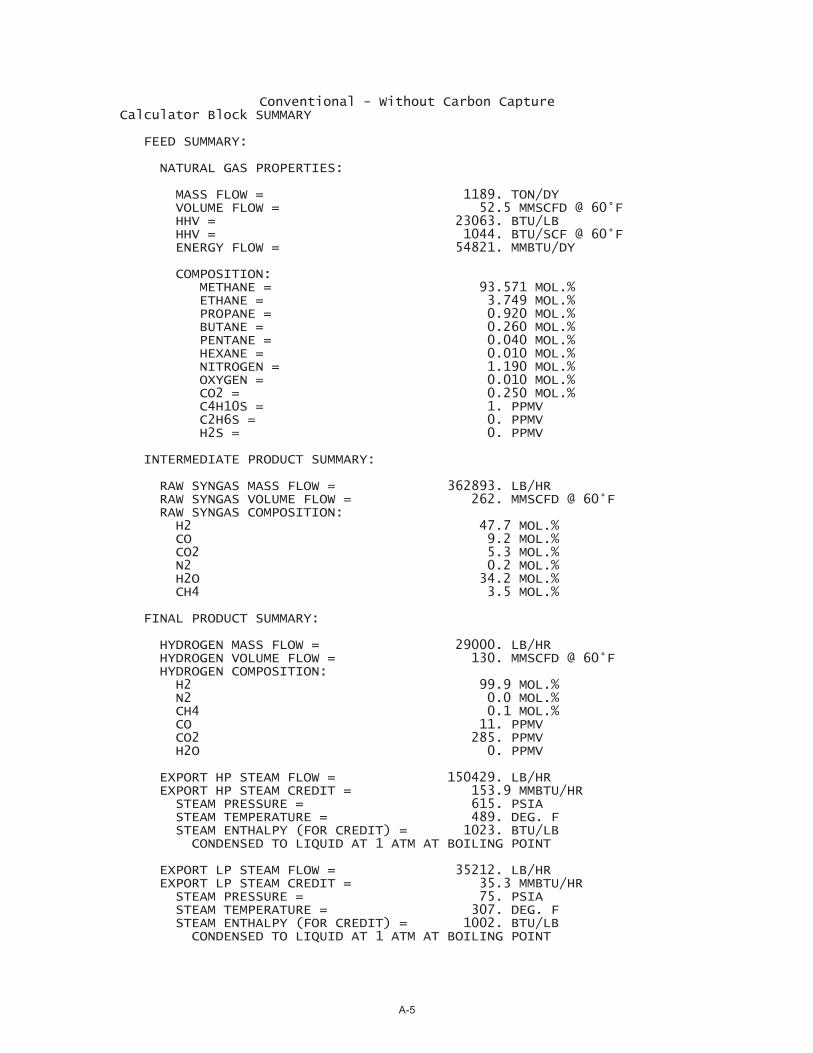
Conventional - Without Carbon Capture Calculator Block SUMMARY
FEED SUMMARY:
NATURAL GAS PROPERTIES:
MASS FLOW = 1189. TON/DY VOLUME FLOW = 52.5 MMSCFD @ 60°F HHV = 23063. BTU/LB HHV = 1044. BTU/SCF @ 60°F ENERGY FLOW = 54821. MMBTU/DY
COMPOSITION: METHANE = 93.571 MOL.% ETHANE = 3.749 MOL.% PROPANE = 0.920 MOL.% BUTANE = 0.260 MOL.% PENTANE = 0.040 MOL.% HEXANE = 0.010 MOL.% NITROGEN = 1.190 MOL.% OXYGEN = 0.010 MOL.% CO2 = 0.250 MOL.% C4H10S = 1. PPMV C2H6S = 0. PPMV H2S = 0. PPMV
INTERMEDIATE PRODUCT SUMMARY:
RAW SYNGAS MASS FLOW = 362893. LB/HR RAW SYNGAS VOLUME FLOW = 262. MMSCFD @ 60°F RAW SYNGAS COMPOSITION: H2 47.7 MOL.% CO 9.2 MOL.% CO2 5.3 MOL.% N2 0.2 MOL.% H2O 34.2 MOL.% CH4 3.5 MOL.%
FINAL PRODUCT SUMMARY:
HYDROGEN MASS FLOW = 29000. LB/HR HYDROGEN VOLUME FLOW = 130. MMSCFD @ 60°F HYDROGEN COMPOSITION: H2 99.9 MOL.% N2 0.0 MOL.% CH4 0.1 MOL.% CO 11. PPMV CO2 285. PPMV H2O 0. PPMV
EXPORT HP STEAM FLOW = 150429. LB/HR EXPORT HP STEAM CREDIT = 153.9 MMBTU/HR STEAM PRESSURE = 615. PSIA STEAM TEMPERATURE = 489. DEG. F STEAM ENTHALPY (FOR CREDIT) = 1023. BTU/LB CONDENSED TO LIQUID AT 1 ATM AT BOILING POINT
EXPORT LP STEAM FLOW = 35212. LB/HR EXPORT LP STEAM CREDIT = 35.3 MMBTU/HR STEAM PRESSURE = 75. PSIA STEAM TEMPERATURE = 307. DEG. F STEAM ENTHALPY (FOR CREDIT) = 1002. BTU/LB CONDENSED TO LIQUID AT 1 ATM AT BOILING POINT
A-5
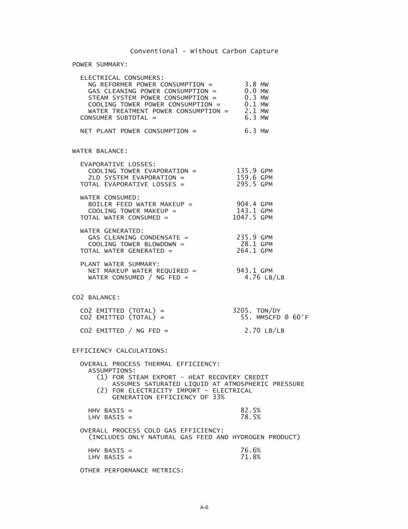
Conventional - Without Carbon Capture
POWER SUMMARY:
ELECTRICAL CONSUMERS: NG REFORMER POWER CONSUMPTION = 3.8 MW GAS CLEANING POWER CONSUMPTION = 0.0 MW STEAM SYSTEM POWER CONSUMPTION = 0.3 MW COOLING TOWER POWER CONSUMPTION = 0.1 MW WATER TREATMENT POWER CONSUMPTION = 2.1 MW CONSUMER SUBTOTAL = 6.3 MW
NET PLANT POWER CONSUMPTION = 6.3 MW
WATER BALANCE:
EVAPORATIVE LOSSES: COOLING TOWER EVAPORATION = 135.9 GPM ZLD SYSTEM EVAPORATION = 159.6 GPM TOTAL EVAPORATIVE LOSSES = 295.5 GPM
WATER CONSUMED: BOILER FEED WATER MAKEUP = 904.4 GPM COOLING TOWER MAKEUP = 143.1 GPM TOTAL WATER CONSUMED = 1047.5 GPM
WATER GENERATED: GAS CLEANING CONDENSATE = 235.9 GPM COOLING TOWER BLOWDOWN = 28.1 GPM TOTAL WATER GENERATED = 264.1 GPM
PLANT WATER SUMMARY: NET MAKEUP WATER REQUIRED = 943.1 GPM WATER CONSUMED / NG FED = 4.76 LB/LB
CO2 BALANCE:
CO2 EMITTED (TOTAL) = 3205. TON/DY CO2 EMITTED (TOTAL) = 55. MMSCFD @ 60°F
CO2 EMITTED / NG FED = 2.70 LB/LB
EFFICIENCY CALCULATIONS:
OVERALL PROCESS THERMAL EFFICIENCY: ASSUMPTIONS: (1) FOR STEAM EXPORT - HEAT RECOVERY CREDIT ASSUMES SATURATED LIQUID AT ATMOSPHERIC PRESSURE (2) FOR ELECTRICITY IMPORT - ELECTRICAL GENERATION EFFICIENCY OF 33%
HHV BASIS = 82.5% LHV BASIS = 78.5%
OVERALL PROCESS COLD GAS EFFICIENCY: (INCLUDES ONLY NATURAL GAS FEED AND HYDROGEN PRODUCT)
HHV BASIS = 76.6% LHV BASIS = 71.8%
OTHER PERFORMANCE METRICS:
A-6
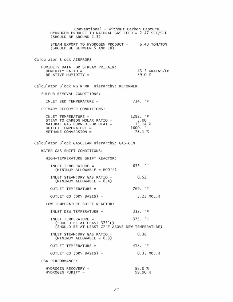
Conventional - Without Carbon Capture HYDROGEN PRODUCT TO NATURAL GAS FEED = 2.47 SCF/SCF (SHOULD BE AROUND 2.5)
STEAM EXPORT TO HYDROGEN PRODUCT = 6.40 TON/TON (SHOULD BE BETWEEN 5 AND 18)
Calculator Block AIRPROPS
HUMIDITY DATA FOR STREAM PRI-AIR: HUMIDITY RATIO = 43.5 GRAINS/LB RELATIVE HUMIDITY = 39.0 %
Calculator Block NG-RFMR Hierarchy: REFORMER
SULFUR REMOVAL CONDITIONS:
INLET BED TEMPERATURE = 734. °F
PRIMARY REFORMER CONDITIONS:
INLET TEMPERATURE = 1292. °F STEAM TO CARBON MOLAR RATIO = 3.00 NATURAL GAS BURNED FOR HEAT = 15.14 % OUTLET TEMPERATURE = 1600. °F METHANE CONVERSION = 78.1 %
Calculator Block GASCLEAN Hierarchy: GAS-CLN
WATER GAS SHIFT CONDITIONS:
HIGH-TEMPERATURE SHIFT REACTOR:
INLET TEMPERATURE = 635. °F (MINIMUM ALLOWABLE = 600°F)
INLET STEAM:DRY GAS RATIO = 0.52 (MINIMUM ALLOWABLE = 0.4)
OUTLET TEMPERATURE = 769. °F
OUTLET CO (DRY BASIS) = 3.23 MOL.%
LOW-TEMPERATURE SHIFT REACTOR:
INLET DEW TEMPERATURE = 332. °F
INLET TEMPERATURE = 375. °F (SHOULD BE AT LEAST 375°F) (SHOULD BE AT LEAST 27°F ABOVE DEW TEMPERATURE)
INLET STEAM:DRY GAS RATIO = 0.38 (MINIMUM ALLOWABLE = 0.3)
OUTLET TEMPERATURE = 418. °F
OUTLET CO (DRY BASIS) = 0.35 MOL.%
PSA PERFORMANCE:
HYDROGEN RECOVERY = 88.0 % HYDROGEN PURITY = 99.90 %
A-7
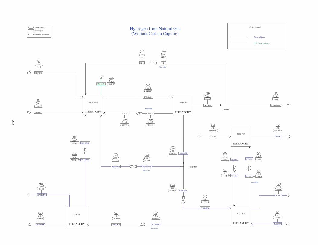
HIERARCHY
COOL-TWR
HIERARCHY
GAS-CLN
HIERARCHY
H2O-TRTM
HIERARCHY
REFORMER
HIERARCHY
STEAM
70
15
1314459
AIR-CT
60
15
71619CT-MU2
104
15
1372007
CT-EX
86
30
14075 CT-BD1
635
439
362893
SYNGAS-1
104
390
129781 CONDSTE
131
25
203909
FUEL-1
131
379
29204
H2-PROD
104
390
118061
COND-BD2
86
30
14075 CT-BD2
60
15
471914
MAKEUP
182
15
452565
BFW-MU1
275
15
79864
ZLD-EX
60
15
71619CT-MU1
488
615
266924 REF-STM2
70
15
735412
REF-AIR
104
390
11720
REF-WAT2
70
315
99043
NAT-GAS
131
379
204
H2-2
131
25
203909
FUEL-2
300
15
954318PRI-EXST
182
15
452565
BFW-MU2
307
75
35212
LPS-EXPT
489
615
150430
HPS-EXPT
104
390
11720
REF-WAT1
104
390
118061 COND-BD1
131
379
29000
HYDROGEN
131
379
204
H2-1
H2O-SPLT
H2-SPLT
Temperature (F)
Pressure (psi)
Mass Flow Rate (lb/hr)
Hydrogen from Natural Gas(Without Carbon Capture)
Reconcile
Water or Steam
CO2 Emissions Source
Color Legend
Reconcile
Reconcile
Reconcile
Reconcile
489
615
266924 REF-STM1
A-8

488
615
266924
STEAM-1REF-STM2(IN)
70
15
735412
AIR-1REF-AIR(IN)
104
390
11720
WATER-1REF-WAT2(IN)
70
315
99043
NAT-GASNAT-GAS(IN)
131
379
204
H2-1H2-2(IN)
131
25
203909FUEL-GAS
FUEL-2(IN)
635
439
362893SG-2
SYNGAS-1(OUT)
300
15
954318
EXHAUSTPRI-EXST(OUT)
1220
17
954318
EX-4
136
460
84250NG-3
430
457
84250NG-4
1166
17
954318
EX-5
752
454
95970NG-6
734
451
95970
NG-7
70
15
0S-CAPTUR
734
448
95969
NG-8
430
457
11720
WATER-3
276
457
95970NG-5
1330
18
954318
EX-3
1022
612
266924STEAM-2
911
448
362893NG-9
70
315
84046
NG-1
70
315
14997NG-BURN
1875
19
954318
EX-1
1292
445
362893
NG-10
1588
18
954318
EX-2
1600
442
362893SG-1
-449
REF-HEAT
550
19
735412
AIR-3
122
25
218906
FUEL
128
19
735412AIR-2
104
460
11720 WATER-2
135
460
84046
NG-2
1152
16
954318
EX-6
884
16
954318
EX-7
182
465
204
H2-2
PRE-HT-5
Q=15.8
HYD-GEN
Q=0.0
S-REMOVEQ=0.0
SATURATR
PRE-HT-6
Q=32.3
MIX-1
SPLT-1
PRE-HT-8
Q=88.4
PRI-RFMR
Q=449.0
BURNER
Q=-449.0
AIR-BLR
W=3027.3
H2O-PUMP
W=2.4
NG-COMPW=787.7
HPS-GENQ=-240.5
PRE-HT-4
Q=4.3 PRE-HT-7
Q=77.9
PRE-HT-3
Q=76.3
H2-MIX
PRE-HT-2
Q=-109.6
FUEL-MIX
H2-COMP
W=10.2
Temperature (F)
Pressure (psi)
Mass Flow Rate (lb/hr)
Duty (MMBtu/hr)
Q Duty (MMBtu/hr)
W Power(kW)
Natural Gas Steam Reforming
Furnace
Manual Adjust
PRE-HT-1Q=-46.5
480
15
954318EX-8
A-9

635
439
362893
SG-1SYNGAS-1(IN)
104
390
129781COND
CONDSTE(OUT)
131
25
203909
PURGE FUEL-1(OUT)
131
379
29204
H2 H2-PROD(OUT)
480
419
362893
SG-3
418
399
362893
SG-5
769
422
362893
SG-2
104
392
129781
KO-LIQ-1
104
390
0COND-VNT
300
396
362893
SG-6
104
392
233113
SG-8
WGS-2
Q=0.0WGS-EX1
Q=-69.2
WGS-1
Q=0.0
CON-TANK
Q=0.0
KO-DRM-1
Q=-20.0
WGS-EX3
Q=-69.6
PSA
Q=0.9
COMPR
PSA-PWRW=21.2
Temperature (F)
Pressure (psi)
Mass Flow Rate (lb/hr)
Q Duty (MMBtu/hr)
W Power(kW)
Syngas Cleaning & Conditioning
Used to includePSA power
requirement inutility calcs.
WGS-EX2
Q=-24.6
WGS-EX4
Q=-118.0
375
416
362893
SG-4
158
393
362893
SG-7
WGS-EX5
Q=4.4
131
389
233113
SG-9
A-10
182
15
452565MAKE-UP
BFW-MU2(IN)
307
75
35212 LPS-EXP2
LPS-EXPT(OUT)
489
615
150430 HPS-EXP2
HPS-EXPT(OUT)
307
75
13488
LPS-DA
204
21
546651
COND-2
228
21
560139COND-3
228
21
142786LP-FW-1
228
21
417354HP-FW-1
228
75
142786LP-FW-2
204
15
546651
COND-1
229
615
417354
HP-FW-2
489
615
417353
HPS-1
489
615
266924
HPS-INJ REF-STM1(OUT)
489
615
150430 HPS-EXP1
307
75
142786
LPS-1
307
75
107574
LPS-2
307
75
35212 LPS-EXP1
307
75
94087LPS-USRS
307
75
94087
LP-COND
489
615
417354 HPS
307
75
142786LPS
307
75
35212
LP-CRD-1
489
615
150430
HP-CRD-1
212
15
35212LP-CRD-2
212
15
150430HP-CRD-2
DA
BFW-SPLT
LP-PUMPW=10.5
COND-PMP
W=4.0
HP-PUMP
W=297.4
HP-SPLT1
LP-SPLT1LP-SPLT2
LPS-USRS
Q=-85.1
HPS-GENSQ=419.3
LPS-GENS
Q=140.7
LP-DUP
HP-DUP
LP-CREDTQ=-35.3
HP-CREDTQ=-153.9
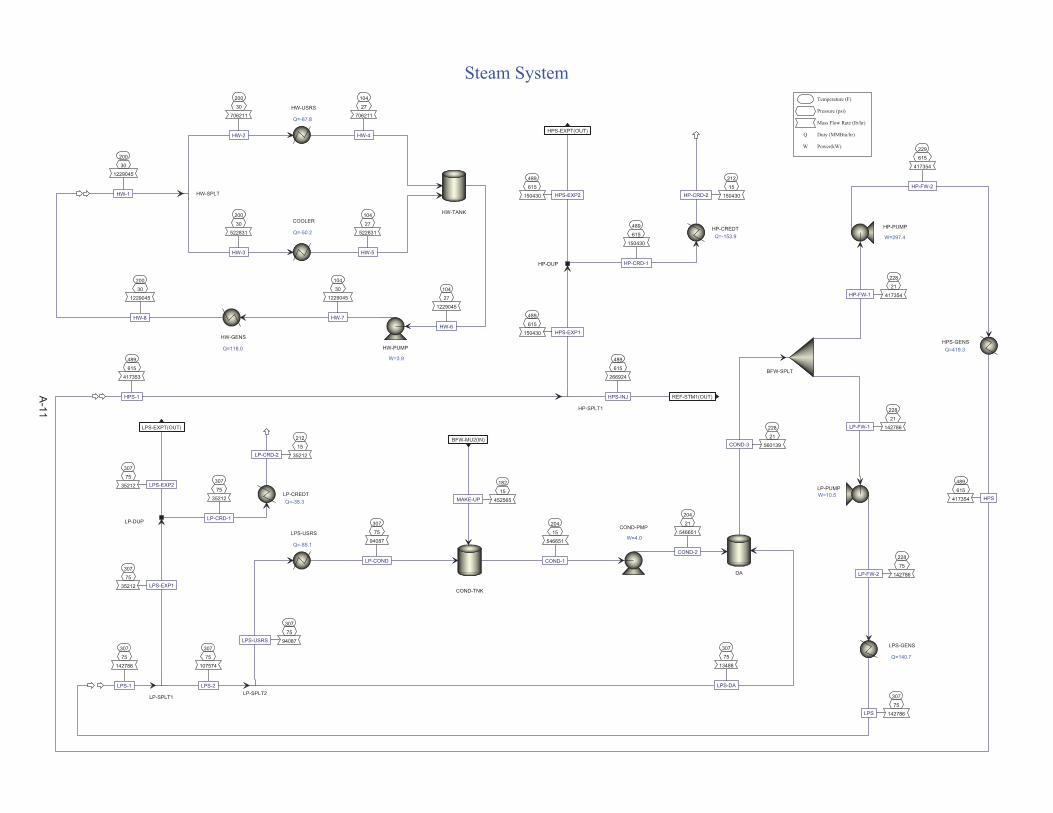
Temperature (F)
Pressure (psi)
Mass Flow Rate (lb/hr)
Q Duty (MMBtu/hr)
W Power(kW)
Steam System
COND-TNK
200
30
1229045
HW-1
HW-USRS
Q=-67.8
COOLER
Q=-50.2
HW-SPLT
200
30
706211
HW-2
200
30
522831
HW-3
HW-TANK
104
27
706211
HW-4
104
27
522831
HW-5
104
27
1229045
HW-6
HW-PUMP
W=3.9
200
30
1229045
HW-8
HW-GENS
Q=118.0
104
30
1229045
HW-7
A-11

70
15
1314459
AIR-1AIR-CT(IN)
60
15
71619
MU-H2OCT-MU2(IN)
104
15
1372007
AIR-3 CT-EX(OUT)
86
30
14075
BLOWDOWN CT-BD1(OUT)
39
HEAT
122
25
1954835
CWR-1
104
15
1897294
CWS-1
104
15
1372007 AIR-2
86
15
1968906
CWS-3
86
30
1968906
CWS-4
86
30
1954835
CWS-6
86
15
1968906
CWS-2
86
30
1954835
CWS-5
CT-FLASH
Q=39.0
CWS-PUMPW=30.9
CT-FAN
W=31.1
CW-USERS
Q=70.2
CT-COOL
Q=-39.0
BLOWDOWN
COLDWELL
Q=0.0
Temperature (F)
Pressure (psi)
Mass Flow Rate (lb/hr)
Duty (MMBtu/hr)
Q Duty (MMBtu/hr)
W Power(kW)
Cooling Tower
A-12

104
390
118061REF-1
COND-BD2(IN)
86
30
14075COOL-1
CT-BD2(IN)
60
15
471914MKUP-1
MAKEUP(IN)
182
15
452565
TO-HRSGBFW-MU1(OUT)
275
15
79864
EVAP-EXHZLD-EX(OUT)
60
15
71619TO-CT
CT-MU1(OUT)
105
15
118061BIO-EFF
62
15
414369
COOL-2
72
15
452565
RO-EFF
72
15
79864
RO-BD
60
15
400294
MKUP-3
60
15
471914MKUP-2
MIXER
BIOTREAT
FSPLIT
UF-RO
MIXER
POLISH
HEATER
ZLDQ=85.1
MIXER
SOFTEN
MIXER
CLARIFY
COMPR
PWR-CALCW=2069.2
SPLT
Temperature (F)
Pressure (psi)
Mass Flow Rate (lb/hr)
Q Duty (MMBtu/hr)
W Power(kW)
Simplified Water Treatment
PRHT-1
Q=9.5182
15
79864
RO-HOT
PRHT-2
Q=53.972
15
452565
POL-EFF
A-13
D
C
B
A
4 3 2 1
D
C
B
A
4 3 2 1
Shift & SyngasConditioning
SteamSystem
SteamReformer H2
Hydrogen From Natural Gas via Steam Reforming(With Carbon Capture)
SHEET 1 OF 1
REV
0
DWG NO
SMR-H2-BFD-3
Date
July 7, 2010
PREPARED BY R. Wood
SIZE
LTR
TYPE Block Flow Diagram
H2-Rich Syngas
SulfurRemoval
NaturalGas Steam
NaturalGas
Exhaust
NaturalGas
NaturalGas
Water
PlantWater
Treatment
CoolingTowers
Water
WaterWater
CH4-Rich Tailgas
Air
FinalProduct
Byproduct
ExportSteam
EmissionsSource
Makeup Water
General Plant Support
CO2
Byproduct
A-14
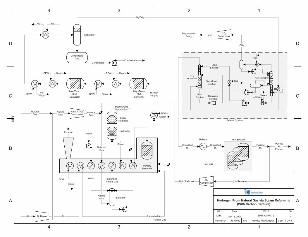
D
C
B
A
4 3 2 1
D
C
B
A
4 3 2 1
Hydrogen From Natural Gas via Steam Reforming(With Carbon Capture)
SHEET 1 OF 1
REV
0
DWG NO
SMR-H2-PFD-2
Date
July 12, 2009
PREPARED BY R. Wood
SIZE
LTR
TYPE Process Flow Diagram
PurifiedH2
Natural GasCompressor
PrimaryReformer
Preheated Air
NatauralGas
Exhaust
Air
BFWSteam
H2-RichSyngas
High-TempShift
Converter
Low-TempShift
Converter
Separator
CondensateCondensate
SequestrationReady
Air Blower AirNatural Gas
NaturalGas
Water
Steam
DesulfurizedNatural Gas
NaturalGas
Water
SaturatedNatural Gas
NaturalGas
Hytrotreater
SulfurRemoval
Saturator
BFW
Steam
BFW Steam
BFW Steam
BFW Steam
BFW HotWater
CWCW
Fuel Gas
CO2CompressorCO2
CondensateTank
Reheat
UnpurifiedH2
H2Compressor H2 to ReformerH2 to Reformer
NatauralGas
PurifiedH2
Product
PSA System
CO2Absorber CO2 Stripper
HydraulicTurbine
RichSolution
Semi-LeanSolution
BFWSteam
CW
LeanSolution
CW
Selexol System
UnpurifiedH2
CO2
H2/CO2
A-15
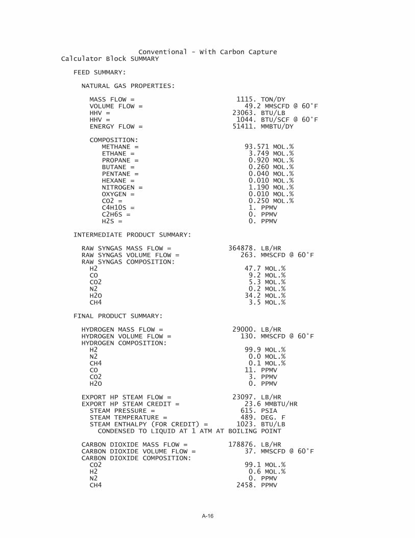
Conventional - With Carbon Capture Calculator Block SUMMARY
FEED SUMMARY:
NATURAL GAS PROPERTIES:
MASS FLOW = 1115. TON/DY VOLUME FLOW = 49.2 MMSCFD @ 60°F HHV = 23063. BTU/LB HHV = 1044. BTU/SCF @ 60°F ENERGY FLOW = 51411. MMBTU/DY
COMPOSITION: METHANE = 93.571 MOL.% ETHANE = 3.749 MOL.% PROPANE = 0.920 MOL.% BUTANE = 0.260 MOL.% PENTANE = 0.040 MOL.% HEXANE = 0.010 MOL.% NITROGEN = 1.190 MOL.% OXYGEN = 0.010 MOL.% CO2 = 0.250 MOL.% C4H10S = 1. PPMV C2H6S = 0. PPMV H2S = 0. PPMV
INTERMEDIATE PRODUCT SUMMARY:
RAW SYNGAS MASS FLOW = 364878. LB/HR RAW SYNGAS VOLUME FLOW = 263. MMSCFD @ 60°F RAW SYNGAS COMPOSITION: H2 47.7 MOL.% CO 9.2 MOL.% CO2 5.3 MOL.% N2 0.2 MOL.% H2O 34.2 MOL.% CH4 3.5 MOL.%
FINAL PRODUCT SUMMARY:
HYDROGEN MASS FLOW = 29000. LB/HR HYDROGEN VOLUME FLOW = 130. MMSCFD @ 60°F HYDROGEN COMPOSITION: H2 99.9 MOL.% N2 0.0 MOL.% CH4 0.1 MOL.% CO 11. PPMV CO2 3. PPMV H2O 0. PPMV
EXPORT HP STEAM FLOW = 23097. LB/HR EXPORT HP STEAM CREDIT = 23.6 MMBTU/HR STEAM PRESSURE = 615. PSIA STEAM TEMPERATURE = 489. DEG. F STEAM ENTHALPY (FOR CREDIT) = 1023. BTU/LB CONDENSED TO LIQUID AT 1 ATM AT BOILING POINT
CARBON DIOXIDE MASS FLOW = 178876. LB/HR CARBON DIOXIDE VOLUME FLOW = 37. MMSCFD @ 60°F CARBON DIOXIDE COMPOSITION: CO2 99.1 MOL.% H2 0.6 MOL.% N2 0. PPMV CH4 2458. PPMV
A-16
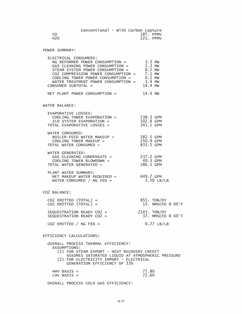
Conventional - With Carbon Capture CO 187. PPMV H2O 221. PPMV
POWER SUMMARY:
ELECTRICAL CONSUMERS: NG REFORMER POWER CONSUMPTION = 3.3 MW GAS CLEANING POWER CONSUMPTION = 2.3 MW STEAM SYSTEM POWER CONSUMPTION = 0.2 MW CO2 COMPRESSION POWER CONSUMPTION = 7.1 MW COOLING TOWER POWER CONSUMPTION = 0.1 MW WATER TREATMENT POWER CONSUMPTION = 1.4 MW CONSUMER SUBTOTAL = 14.4 MW
NET PLANT POWER CONSUMPTION = 14.4 MW
WATER BALANCE:
EVAPORATIVE LOSSES: COOLING TOWER EVAPORATION = 238.3 GPM ZLD SYSTEM EVAPORATION = 102.8 GPM TOTAL EVAPORATIVE LOSSES = 341.1 GPM
WATER CONSUMED: BOILER FEED WATER MAKEUP = 582.5 GPM COOLING TOWER MAKEUP = 250.9 GPM TOTAL WATER CONSUMED = 833.5 GPM
WATER GENERATED: GAS CLEANING CONDENSATE = 237.2 GPM COOLING TOWER BLOWDOWN = 49.3 GPM TOTAL WATER GENERATED = 286.5 GPM
PLANT WATER SUMMARY: NET MAKEUP WATER REQUIRED = 649.7 GPM WATER CONSUMED / NG FED = 3.50 LB/LB
CO2 BALANCE:
CO2 EMITTED (TOTAL) = 855. TON/DY CO2 EMITTED (TOTAL) = 15. MMSCFD @ 60°F
SEQUESTRATION READY CO2 = 2143. TON/DY SEQUESTRATION READY CO2 = 37. MMSCFD @ 60°F
CO2 EMITTED / NG FED = 0.77 LB/LB
EFFICIENCY CALCULATIONS:
OVERALL PROCESS THERMAL EFFICIENCY: ASSUMPTIONS: (1) FOR STEAM EXPORT - HEAT RECOVERY CREDIT ASSUMES SATURATED LIQUID AT ATMOSPHERIC PRESSURE (2) FOR ELECTRICITY IMPORT - ELECTRICAL GENERATION EFFICIENCY OF 33%
HHV BASIS = 77.8% LHV BASIS = 72.6%
OVERALL PROCESS COLD GAS EFFICIENCY:
A-17
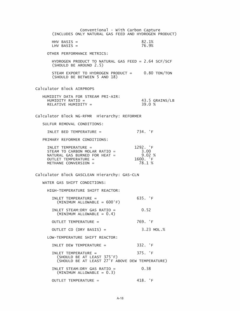
Conventional - With Carbon Capture (INCLUDES ONLY NATURAL GAS FEED AND HYDROGEN PRODUCT)
HHV BASIS = 82.1% LHV BASIS = 76.9%
OTHER PERFORMANCE METRICS:
HYDROGEN PRODUCT TO NATURAL GAS FEED = 2.64 SCF/SCF (SHOULD BE AROUND 2.5)
STEAM EXPORT TO HYDROGEN PRODUCT = 0.80 TON/TON (SHOULD BE BETWEEN 5 AND 18)
Calculator Block AIRPROPS
HUMIDITY DATA FOR STREAM PRI-AIR: HUMIDITY RATIO = 43.5 GRAINS/LB RELATIVE HUMIDITY = 39.0 %
Calculator Block NG-RFMR Hierarchy: REFORMER
SULFUR REMOVAL CONDITIONS:
INLET BED TEMPERATURE = 734. °F
PRIMARY REFORMER CONDITIONS:
INLET TEMPERATURE = 1292. °F STEAM TO CARBON MOLAR RATIO = 3.00 NATURAL GAS BURNED FOR HEAT = 9.02 % OUTLET TEMPERATURE = 1600. °F METHANE CONVERSION = 78.1 %
Calculator Block GASCLEAN Hierarchy: GAS-CLN
WATER GAS SHIFT CONDITIONS:
HIGH-TEMPERATURE SHIFT REACTOR:
INLET TEMPERATURE = 635. °F (MINIMUM ALLOWABLE = 600°F)
INLET STEAM:DRY GAS RATIO = 0.52 (MINIMUM ALLOWABLE = 0.4)
OUTLET TEMPERATURE = 769. °F
OUTLET CO (DRY BASIS) = 3.23 MOL.%
LOW-TEMPERATURE SHIFT REACTOR:
INLET DEW TEMPERATURE = 332. °F
INLET TEMPERATURE = 375. °F (SHOULD BE AT LEAST 375°F) (SHOULD BE AT LEAST 27°F ABOVE DEW TEMPERATURE)
INLET STEAM:DRY GAS RATIO = 0.38 (MINIMUM ALLOWABLE = 0.3)
OUTLET TEMPERATURE = 418. °F
A-18
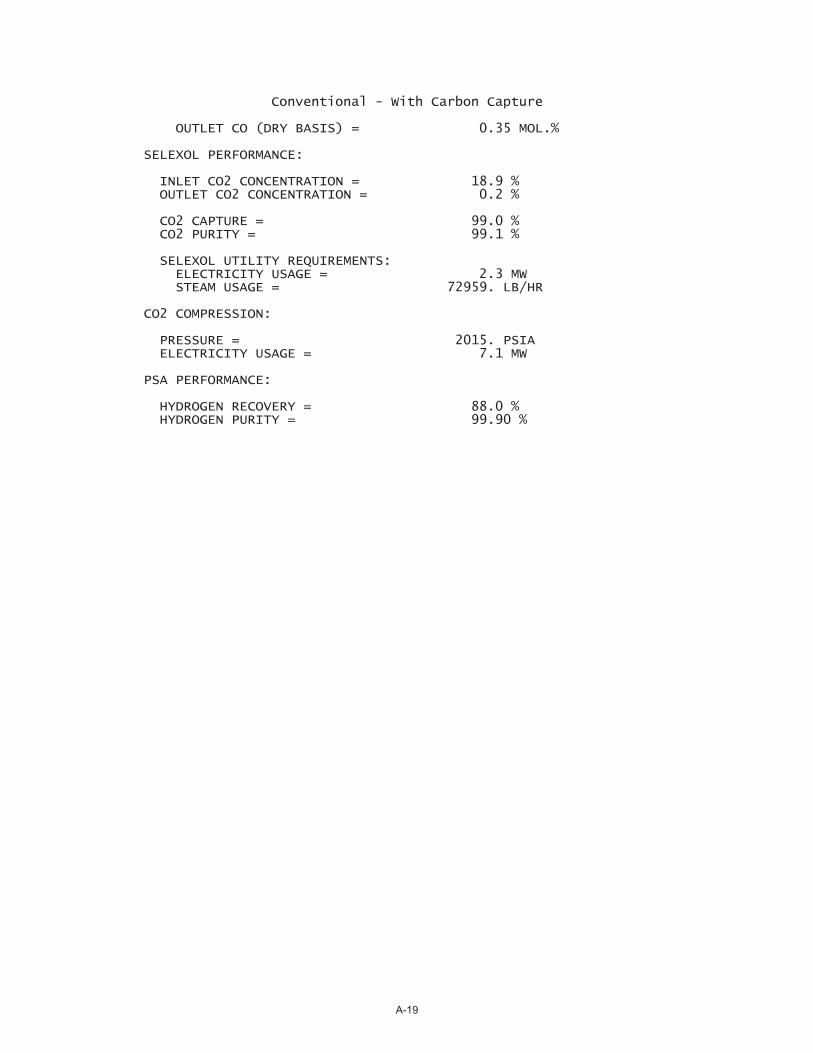
Conventional - With Carbon Capture
OUTLET CO (DRY BASIS) = 0.35 MOL.%
SELEXOL PERFORMANCE:
INLET CO2 CONCENTRATION = 18.9 % OUTLET CO2 CONCENTRATION = 0.2 %
CO2 CAPTURE = 99.0 % CO2 PURITY = 99.1 %
SELEXOL UTILITY REQUIREMENTS: ELECTRICITY USAGE = 2.3 MW STEAM USAGE = 72959. LB/HR
CO2 COMPRESSION:
PRESSURE = 2015. PSIA ELECTRICITY USAGE = 7.1 MW
PSA PERFORMANCE:
HYDROGEN RECOVERY = 88.0 % HYDROGEN PURITY = 99.90 %
A-19
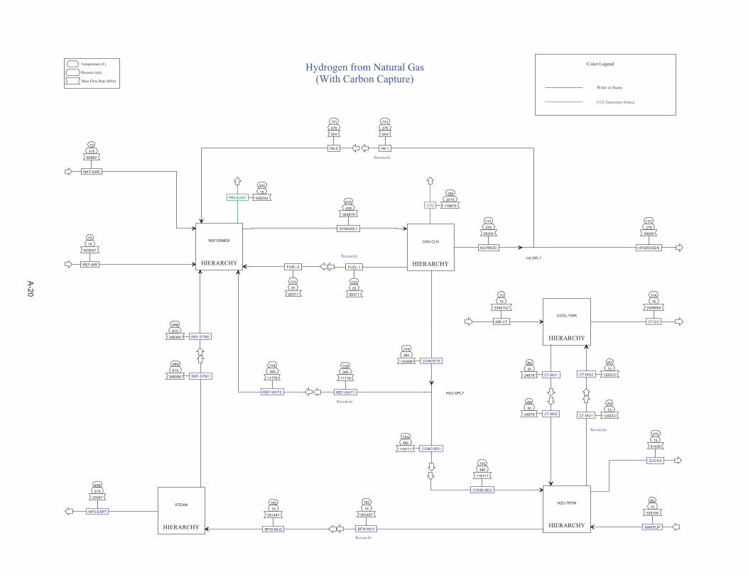
HIERARCHY
COOL-TWR
HIERARCHY
GAS-CLN
HIERARCHY
H2O-TRTM
HIERARCHY
REFORMER
HIERARCHY
STEAM
70
15
2306102
AIR-CT
60
15
125572CT-MU2
104
15
2406993
CT-EX
86
30
24678 CT-BD1
635
439
364878
SYNGAS-1
104
390
130488 CONDSTE
131
25
26311
FUEL-1
131
379
29204
H2-PROD
104
390
118711
COND-BD2
86
30
24678 CT-BD2
60
15
325109
MAKEUP
182
15
291487
BFW-MU1
275
15
51439
ZLD-EX
60
15
125572CT-MU1
488
615
268390 REF-STM2
70
15
603547
REF-AIR
104
390
11778
REF-WAT2
70
315
92882
NAT-GAS
131
379
204
H2-2
131
25
26311
FUEL-2
300
15
638234PRI-EXST
182
15
291487
BFW-MU2
489
615
23097
HPS-EXPT
104
390
11778
REF-WAT1
104
390
118711 COND-BD1
131
379
29000
HYDROGEN
131
379
204
H2-1
H2O-SPLT
H2-SPLT
Temperature (F)
Pressure (psi)
Mass Flow Rate (lb/hr)
Hydrogen from Natural Gas(With Carbon Capture)
Reconcile
Water or Steam
CO2 Emissions Source
Color Legend
Reconcile
Reconcile
Reconcile
Reconcile
489
615
268390 REF-STM1
184
2015
178875CO2
A-20
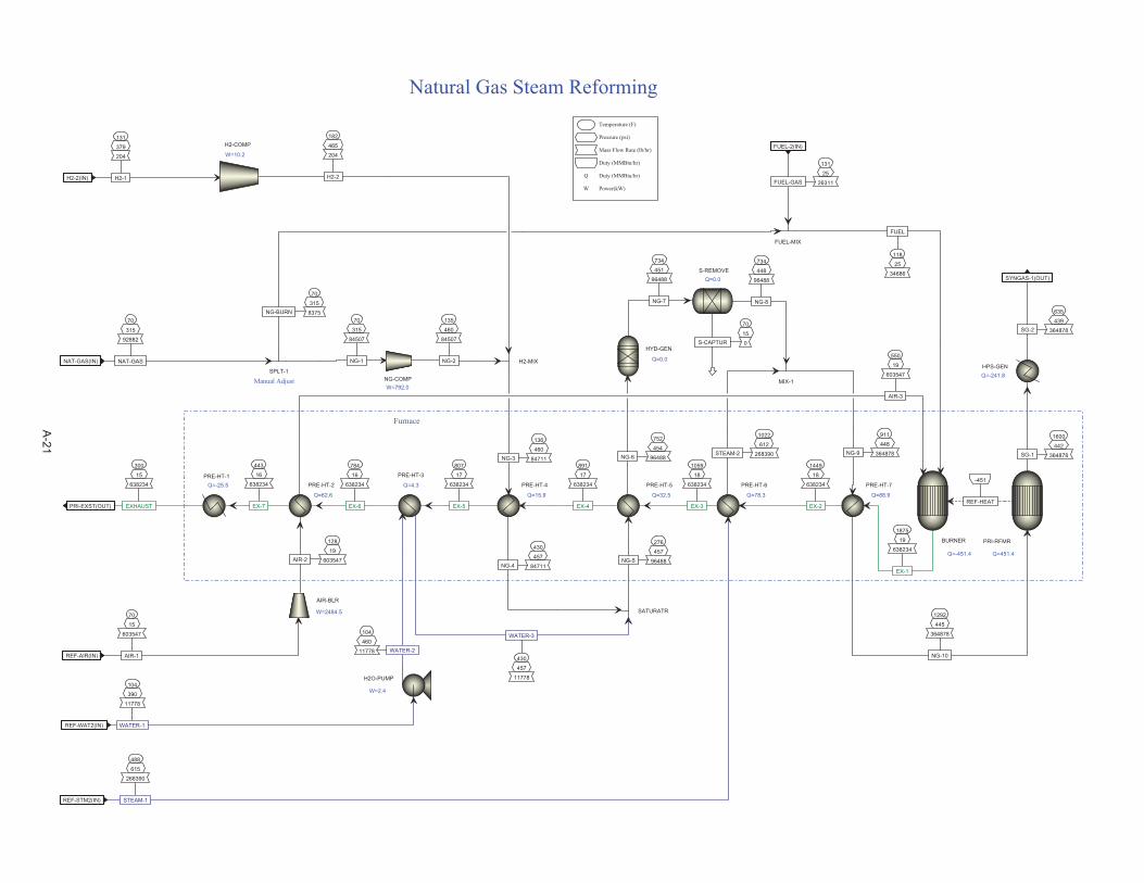
488
615
268390
STEAM-1REF-STM2(IN)
70
15
603547
AIR-1REF-AIR(IN)
104
390
11778
WATER-1REF-WAT2(IN)
70
315
92882
NAT-GASNAT-GAS(IN)
131
379
204
H2-1H2-2(IN)
131
25
26311FUEL-GAS
FUEL-2(IN)
635
439
364878SG-2
SYNGAS-1(OUT)
300
15
638234
EXHAUSTPRI-EXST(OUT)
891
17
638234
EX-4
136
460
84711NG-3
430
457
84711NG-4
807
17
638234
EX-5
752
454
96488NG-6
734
451
96488
NG-7
70
15
0S-CAPTUR
734
448
96488
NG-8
430
457
11778
WATER-3
276
457
96488NG-5
1059
18
638234
EX-3
1022
612
268390STEAM-2
911
448
364878NG-9
70
315
84507
NG-1
70
315
8375NG-BURN
1875
19
638234
EX-1
1292
445
364878
NG-10
1449
18
638234
EX-2
1600
442
364878SG-1
-451
REF-HEAT
550
19
603547
AIR-3
118
25
34686
FUEL
128
19
603547AIR-2
104
460
11778 WATER-2
135
460
84507
NG-2
784
16
638234
EX-6
182
465
204
H2-2
PRE-HT-4
Q=15.9
HYD-GEN
Q=0.0
S-REMOVEQ=0.0
SATURATR
PRE-HT-5
Q=32.5
MIX-1
SPLT-1
PRE-HT-7
Q=88.9
PRI-RFMR
Q=451.4
BURNER
Q=-451.4
AIR-BLR
W=2484.5
H2O-PUMP
W=2.4
NG-COMPW=792.0
HPS-GENQ=-241.8
PRE-HT-3
Q=4.3 PRE-HT-6
Q=78.3
PRE-HT-2
Q=62.6
H2-MIX
FUEL-MIX
H2-COMP
W=10.2
Temperature (F)
Pressure (psi)
Mass Flow Rate (lb/hr)
Duty (MMBtu/hr)
Q Duty (MMBtu/hr)
W Power(kW)
Natural Gas Steam Reforming
Furnace
Manual Adjust
PRE-HT-1Q=-25.5
443
16
638234
EX-7
A-21
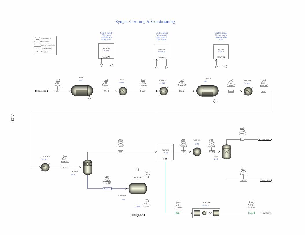
635
439
364878
SG-1SYNGAS-1(IN)
104
390
130488COND
CONDSTE(OUT)
131
25
26311
PURGE FUEL-1(OUT)
131
379
29204
H2 H2-PROD(OUT)
480
419
364878
SG-3
418
399
364878
SG-5
769
422
364878
SG-2
104
392
130488
KO-LIQ-1
104
390
0COND-VNT
300
396
364878
SG-6
104
392
55515
SG-9
WGS-2
Q=0.0WGS-EX1
Q=-69.5
WGS-1
Q=0.0
CON-TANK
Q=0.0
KO-DRM-1
Q=-20.1
WGS-EX3
Q=-70.0
PSA
Q=0.1
COMPR
PSA-PWRW=17.3
Temperature (F)
Pressure (psi)
Mass Flow Rate (lb/hr)
Q Duty (MMBtu/hr)
W Power(kW)
Syngas Cleaning & Conditioning
Used to includePSA power
requirement inutility calcs.
WGS-EX2
Q=-24.7
WGS-EX4
Q=-118.7
375
416
364878
SG-4
158
393
364878
SG-7
WGS-EX5
Q=3.6
131
389
55515
SG-10
104
30
178876
CO2-1
184
2015
178876
CO2-2 CO2(OUT)
CO2-COMP
W=7090.6
SEP
SELEXOL
Q=0.6
104
392
234390
SG-8
HEATER
SEL-STMQ=66.0
COMPR
SEL-PWRW=2279.8
Used to includeSelexol powerrequirement inutility calcs.
Used to includeSelexol steamusage in utility
calcs.
A-22
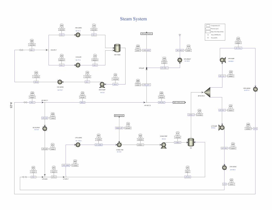
182
15
291487MAKE-UP
BFW-MU2(IN)
489
615
23097 HPS-EXP2
HPS-EXPT(OUT)
307
75
6921
LPS-DA
212
21
425038
COND-2
228
21
431959COND-3
228
21
122031LP-FW-1
228
21
309927HP-FW-1
228
75
122031LP-FW-2
229
615
309927
HP-FW-2
489
615
309927
HPS-1
489
615
268390
HPS-INJ REF-STM1(OUT)
489
615
23097 HPS-EXP1
307
75
122031
LPS-1
489
615
291487
HPS-2
489
615
18440HPS-DS
307
75
133550LPS-USRS
307
75
133550
LP-COND
489
615
309927 HPS
307
75
122031LPS
489
615
23097
HP-CRD-1
212
15
23097HP-CRD-2
DA
BFW-SPLT
LP-PUMPW=9.2
COND-PMP
W=3.2
HP-PUMP
W=228.1
HP-SPLT2
HP-SPLT1
LP-SPLT
LPS-USRS
Q=-120.8
HPS-GENSQ=311.4
LPS-GENS
Q=120.3
HP-DUP
HP-CREDTQ=-23.6
Temperature (F)
Pressure (psi)
Mass Flow Rate (lb/hr)
Q Duty (MMBtu/hr)
W Power(kW)
Steam System
200
30
1235768
HW-1
HW-USRS
Q=-41.3
COOLER
Q=-77.4
HW-SPLT
200
30
430195
HW-2
200
30
805573
HW-3
HW-TANK
104
27
430195
HW-4
104
27
805573
HW-5
104
27
1235768
HW-6
HW-PUMP
W=3.9
200
30
1235768
HW-8
HW-GENS
Q=118.7
104
30
1235768
HW-7
DE-SUPERQ=-0.4
307
75
18440LPS-DS
LPS-MIX
307
75
140471
LPS-2
COND-TNKQ=-4.2
212
15
425038
COND-1
A-23

70
15
2306100
AIR-1AIR-CT(IN)
60
15
125572
MU-H2OCT-MU2(IN)
104
15
2406994
AIR-3 CT-EX(OUT)
86
30
24678
BLOWDOWN CT-BD1(OUT)
68
HEAT
122
25
3427469
CWR-1
104
15
3326575
CWS-1
104
15
2406994 AIR-2
86
15
3452147
CWS-3
86
30
3452147
CWS-4
86
30
3427469
CWS-6
86
15
3452147
CWS-2
86
30
3427469
CWS-5
CT-FLASH
Q=68.4
CWS-PUMPW=53.6
CT-FAN
W=54.6
CW-USERS
Q=123.1
CT-COOL
Q=-68.4
BLOWDOWN
COLDWELL
Q=0.0
Temperature (F)
Pressure (psi)
Mass Flow Rate (lb/hr)
Duty (MMBtu/hr)
Q Duty (MMBtu/hr)
W Power(kW)
Cooling Tower
A-24
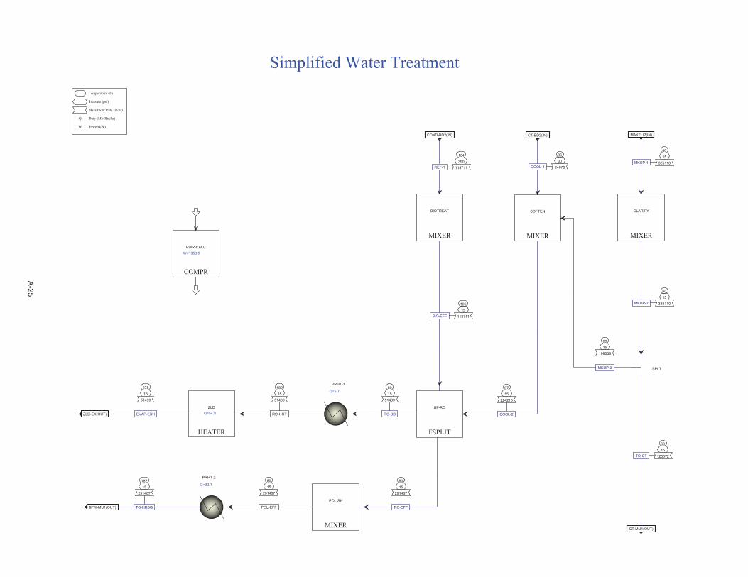
104
390
118711REF-1
COND-BD2(IN)
86
30
24678COOL-1
CT-BD2(IN)
60
15
325110MKUP-1
MAKEUP(IN)
182
15
291487
TO-HRSGBFW-MU1(OUT)
275
15
51439
EVAP-EXHZLD-EX(OUT)
60
15
125572TO-CT
CT-MU1(OUT)
105
15
118711BIO-EFF
67
15
224216
COOL-2
80
15
291487
RO-EFF
80
15
51439
RO-BD
60
15
199538
MKUP-3
60
15
325110MKUP-2
MIXER
BIOTREAT
FSPLIT
UF-RO
MIXER
POLISH
HEATER
ZLDQ=54.8
MIXER
SOFTEN
MIXER
CLARIFY
COMPR
PWR-CALCW=1353.9
SPLT
Temperature (F)
Pressure (psi)
Mass Flow Rate (lb/hr)
Q Duty (MMBtu/hr)
W Power(kW)
Simplified Water Treatment
PRHT-1
Q=5.7182
15
51439
RO-HOT
PRHT-2
Q=32.180
15
291487
POL-EFF
A-25
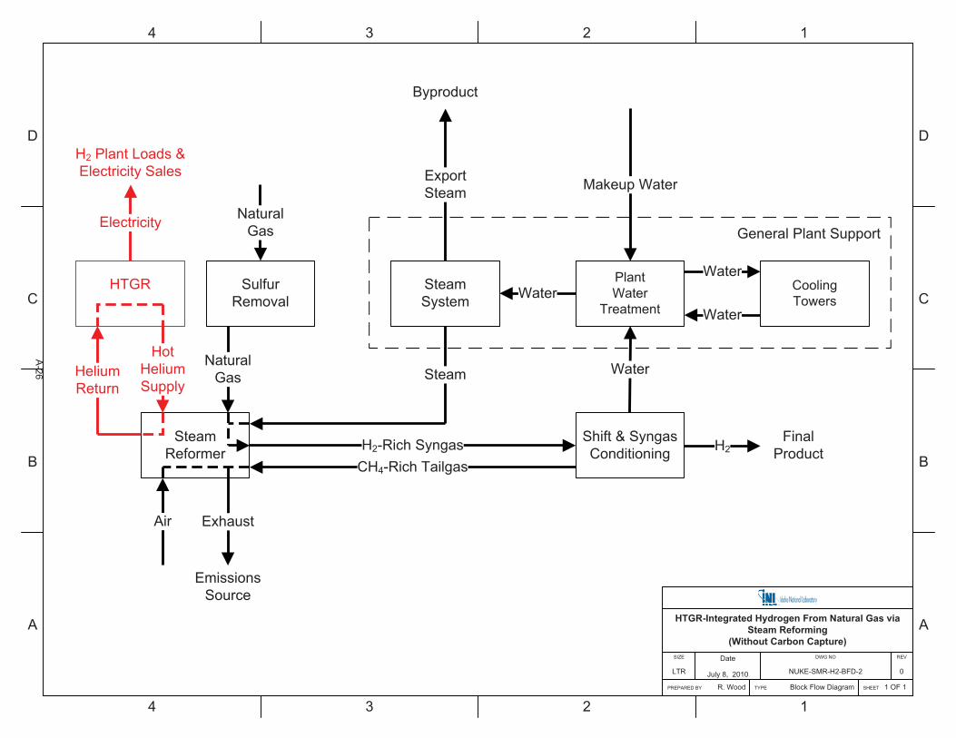
D
C
B
A
4 3 2 1
D
C
B
A
4 3 2 1
Shift & SyngasConditioning
SteamSystem
SteamReformer H2
HTGR-Integrated Hydrogen From Natural Gas via Steam Reforming
(Without Carbon Capture)
SHEET 1 OF 1
REV
0
DWG NO
NUKE-SMR-H2-BFD-2
Date
July 8, 2010
PREPARED BY R. Wood
SIZE
LTR
TYPE Block Flow Diagram
H2-Rich Syngas
SulfurRemoval
NaturalGas Steam
NaturalGas
Exhaust
HotHeliumSupply
Water
PlantWater
Treatment
CoolingTowers
Water
WaterWater
CH4-Rich Tailgas
Air
FinalProduct
ExportSteam
Byproduct
HeliumReturn
EmissionsSource
HTGR
Electricity
H2 Plant Loads &Electricity Sales
General Plant Support
Makeup Water
A-26
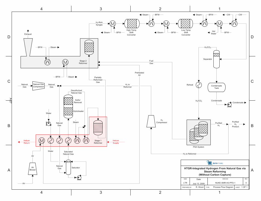
D
C
B
A
4 3 2 1
D
C
B
A
4 3 2 1
HTGR-Integrated Hydrogen From Natural Gas via Steam Reforming
(Without Carbon Capture)
SHEET 1 OF 1
REV
0
DWG NO
NUKE-SMR-H2-PFD-1
Date
July 13, 2009
PREPARED BY R. Wood
SIZE
LTR
TYPE Process Flow Diagram
PurifiedH2
Natural GasCompressor
Stage 1Reformer
PreheatedAir
NaturalGas
Exhaust
Air
BFW
H2-RichSyngas
High-TempShift
Converter
Low-TempShift
Converter
Separator
CondensateCondensate
AirBlower
Air
NaturalGas
Water
Steam
DesulfurizedNatural Gas
Water
SaturatedNatural Gas
NaturalGas
Hytrotreater
SulfurRemoval
Saturator
BFW Steam
BFWSteam
BFWSteam
BFWSteam
BFWHotWater
CWCW
FuelGas
H2/CO2
CondensateTank
Reheat
H2/CO2
H2Compressor
H2 to Reformer
PurifiedH2
Product
H2 toReformer
NaturalGas
Steam
Stage 2Reformer
HeliumReturn
PartiallyReformed
Gas
BFW Steam
HeliumSupply
PSA System
A-27
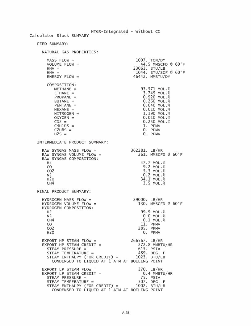
HTGR-Integrated - Without CC Calculator Block SUMMARY
FEED SUMMARY:
NATURAL GAS PROPERTIES:
MASS FLOW = 1007. TON/DY VOLUME FLOW = 44.5 MMSCFD @ 60°F HHV = 23063. BTU/LB HHV = 1044. BTU/SCF @ 60°F ENERGY FLOW = 46442. MMBTU/DY
COMPOSITION: METHANE = 93.571 MOL.% ETHANE = 3.749 MOL.% PROPANE = 0.920 MOL.% BUTANE = 0.260 MOL.% PENTANE = 0.040 MOL.% HEXANE = 0.010 MOL.% NITROGEN = 1.190 MOL.% OXYGEN = 0.010 MOL.% CO2 = 0.250 MOL.% C4H10S = 1. PPMV C2H6S = 0. PPMV H2S = 0. PPMV
INTERMEDIATE PRODUCT SUMMARY:
RAW SYNGAS MASS FLOW = 362281. LB/HR RAW SYNGAS VOLUME FLOW = 261. MMSCFD @ 60°F RAW SYNGAS COMPOSITION: H2 47.7 MOL.% CO 9.2 MOL.% CO2 5.3 MOL.% N2 0.2 MOL.% H2O 34.1 MOL.% CH4 3.5 MOL.%
FINAL PRODUCT SUMMARY:
HYDROGEN MASS FLOW = 29000. LB/HR HYDROGEN VOLUME FLOW = 130. MMSCFD @ 60°F HYDROGEN COMPOSITION: H2 99.9 MOL.% N2 0.0 MOL.% CH4 0.1 MOL.% CO 11. PPMV CO2 285. PPMV H2O 0. PPMV
EXPORT HP STEAM FLOW = 266567. LB/HR EXPORT HP STEAM CREDIT = 272.8 MMBTU/HR STEAM PRESSURE = 615. PSIA STEAM TEMPERATURE = 489. DEG. F STEAM ENTHALPY (FOR CREDIT) = 1023. BTU/LB CONDENSED TO LIQUID AT 1 ATM AT BOILING POINT
EXPORT LP STEAM FLOW = 370. LB/HR EXPORT LP STEAM CREDIT = 0.4 MMBTU/HR STEAM PRESSURE = 75. PSIA STEAM TEMPERATURE = 307. DEG. F STEAM ENTHALPY (FOR CREDIT) = 1002. BTU/LB CONDENSED TO LIQUID AT 1 ATM AT BOILING POINT
A-28
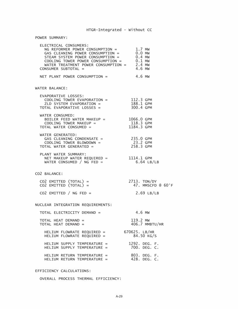
HTGR-Integrated - Without CC
POWER SUMMARY:
ELECTRICAL CONSUMERS: NG REFORMER POWER CONSUMPTION = 1.7 MW GAS CLEANING POWER CONSUMPTION = 0.0 MW STEAM SYSTEM POWER CONSUMPTION = 0.4 MW COOLING TOWER POWER CONSUMPTION = 0.1 MW WATER TREATMENT POWER CONSUMPTION = 2.4 MW CONSUMER SUBTOTAL = 4.6 MW
NET PLANT POWER CONSUMPTION = 4.6 MW
WATER BALANCE:
EVAPORATIVE LOSSES: COOLING TOWER EVAPORATION = 112.3 GPM ZLD SYSTEM EVAPORATION = 188.1 GPM TOTAL EVAPORATIVE LOSSES = 300.4 GPM
WATER CONSUMED: BOILER FEED WATER MAKEUP = 1066.0 GPM COOLING TOWER MAKEUP = 118.3 GPM TOTAL WATER CONSUMED = 1184.3 GPM
WATER GENERATED: GAS CLEANING CONDENSATE = 235.0 GPM COOLING TOWER BLOWDOWN = 23.2 GPM TOTAL WATER GENERATED = 258.3 GPM
PLANT WATER SUMMARY: NET MAKEUP WATER REQUIRED = 1114.1 GPM WATER CONSUMED / NG FED = 6.64 LB/LB
CO2 BALANCE:
CO2 EMITTED (TOTAL) = 2713. TON/DY CO2 EMITTED (TOTAL) = 47. MMSCFD @ 60°F
CO2 EMITTED / NG FED = 2.69 LB/LB
NUCLEAR INTEGRATION REQUIREMENTS:
TOTAL ELECTRICITY DEMAND = 4.6 MW
TOTAL HEAT DEMAND = 119.2 MW TOTAL HEAT DEMAND = 406.7 MMBTU/HR
HELIUM FLOWRATE REQUIRED = 670625. LB/HR HELIUM FLOWRATE REQUIRED = 84.50 KG/S
HELIUM SUPPLY TEMPERATURE = 1292. DEG. F. HELIUM SUPPLY TEMPERATURE = 700. DEG. C.
HELIUM RETURN TEMPERATURE = 803. DEG. F. HELIUM RETURN TEMPERATURE = 428. DEG. C.
EFFICIENCY CALCULATIONS:
OVERALL PROCESS THERMAL EFFICIENCY:
A-29

HTGR-Integrated - Without CC ASSUMPTIONS: (1) FOR STEAM EXPORT - HEAT RECOVERY CREDIT ASSUMES SATURATED LIQUID AT ATMOSPHERIC PRESSURE (2) FOR ELECTRICITY IMPORT - ELECTRICAL GENERATION EFFICIENCY OF 40%
HHV BASIS = 85.0% LHV BASIS = 80.0%
OVERALL PROCESS COLD GAS EFFICIENCY: (INCLUDES ONLY NATURAL GAS FEED AND HYDROGEN PRODUCT)
HHV BASIS = 90.4% LHV BASIS = 84.8%
OTHER PERFORMANCE METRICS:
HYDROGEN PRODUCT TO NATURAL GAS FEED = 2.91 SCF/SCF (CONVENTIONAL PROCESS IS AROUND 2.5)
STEAM EXPORT TO HYDROGEN PRODUCT = 9.20 TON/TON (CONVENTIONAL PROCESS IS TYPICALLY BETWEEN 5 AND 18)
Calculator Block AIRPROPS
HUMIDITY DATA FOR STREAM PRI-AIR: HUMIDITY RATIO = 43.5 GRAINS/LB RELATIVE HUMIDITY = 39.0 %
Calculator Block NG-RFMR Hierarchy: REFORMER
SULFUR REMOVAL CONDITIONS:
INLET BED TEMPERATURE = 734. °F
PRIMARY REFORMER CONDITIONS:
STAGE 1:
INLET TEMPERATURE = 1000. °F STEAM TO CARBON MOLAR RATIO = 3.00 OUTLET TEMPERATURE = 1247. °F METHANE CONVERSION = 28.0 %
STAGE 2:
INLET TEMPERATURE = 1247. °F STEAM TO CARBON MOLAR RATIO = 2.37 OUTLET TEMPERATURE = 1600. °F METHANE CONVERSION = 69.8 %
OVERALL METHANE CONVERSION = 78.2 %
Calculator Block GASCLEAN Hierarchy: GAS-CLN
WATER GAS SHIFT CONDITIONS:
HIGH-TEMPERATURE SHIFT REACTOR:
INLET TEMPERATURE = 635. °F (MINIMUM ALLOWABLE = 600°F)
A-30
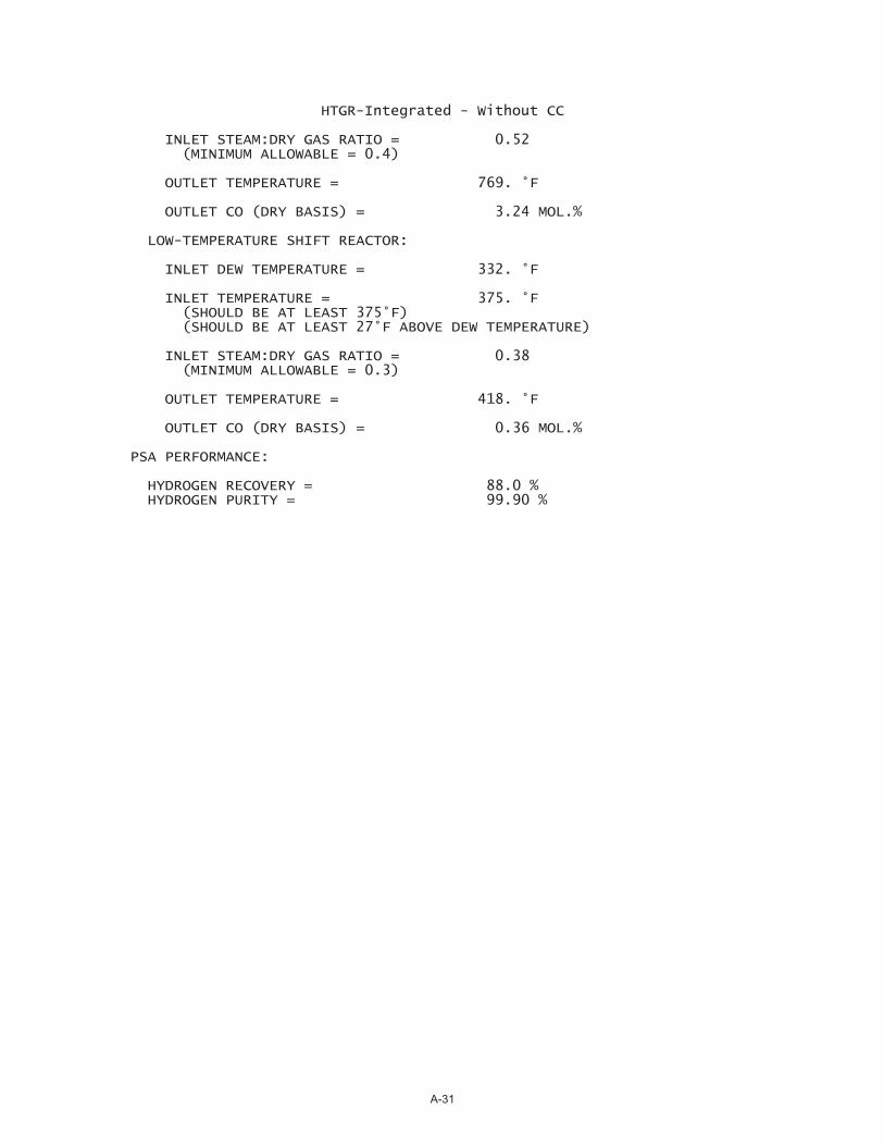
HTGR-Integrated - Without CC
INLET STEAM:DRY GAS RATIO = 0.52 (MINIMUM ALLOWABLE = 0.4)
OUTLET TEMPERATURE = 769. °F
OUTLET CO (DRY BASIS) = 3.24 MOL.%
LOW-TEMPERATURE SHIFT REACTOR:
INLET DEW TEMPERATURE = 332. °F
INLET TEMPERATURE = 375. °F (SHOULD BE AT LEAST 375°F) (SHOULD BE AT LEAST 27°F ABOVE DEW TEMPERATURE)
INLET STEAM:DRY GAS RATIO = 0.38 (MINIMUM ALLOWABLE = 0.3)
OUTLET TEMPERATURE = 418. °F
OUTLET CO (DRY BASIS) = 0.36 MOL.%
PSA PERFORMANCE:
HYDROGEN RECOVERY = 88.0 % HYDROGEN PURITY = 99.90 %
A-31

HIERARCHY
COOL-TWR
HIERARCHY
GAS-CLN
HIERARCHY
H2O-TRTM
HIERARCHY
REFORMER
HIERARCHY
STEAM
70
15
1082280
AIR-CT
60
15
59195CT-MU2
104
15
1129836
CT-EX
86
30
11632 CT-BD1
635
436
362281
SYNGAS-1
104
387
129312 CONDSTE
131
25
203765
FUEL-1
131
376
29204
H2-PROD
104
387
117618
COND-BD2
86
30
11632 CT-BD2
60
15
557493
MAKEUP
182
15
533415
BFW-MU1
275
15
94132
ZLD-EX
60
15
59195CT-MU1
488
615
266478 REF-STM2
70
15
460095
REF-AIR
104
387
11695
REF-WAT2
70
315
83905
NAT-GAS
131
376
203
H2-2
131
25
203765
FUEL-2
300
15
663860PRI-EXST
182
15
533415
BFW-MU2
307
75
370
LPS-EXPT
489
615
266567
HPS-EXPT
104
387
11695
REF-WAT1
104
387
117618 COND-BD1
131
376
29000
HYDROGEN
131
376
203
H2-1
H2O-SPLT
H2-SPLT
Temperature (F)
Pressure (psi)
Mass Flow Rate (lb/hr)
HTGR-Integrated Hydrogen fromNatural Gas (Without Carbon Capture)
Reconcile
Water or Steam
CO2 Emissions Source
Color Legend
Reconcile
Reconcile
Reconcile
Reconcile
489
615
266478 REF-STM1
1292
1015
670626
HE-SUP
803
945
670626
HE-RET
A-32
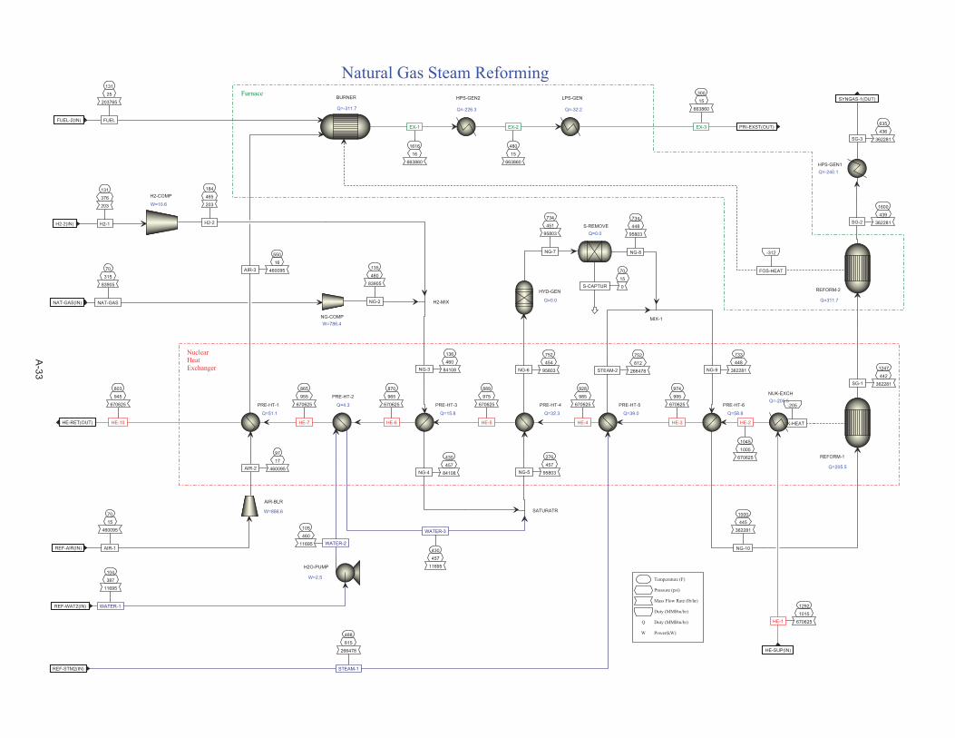
488
615
266478
STEAM-1REF-STM2(IN)
70
15
460095
AIR-1REF-AIR(IN)
104
387
11695
WATER-1REF-WAT2(IN)
70
315
83905
NAT-GASNAT-GAS(IN)
131
376
203
H2-1H2-2(IN)
635
436
362281SG-3
SYNGAS-1(OUT)
803
945
670625
HE-10HE-RET(OUT)
889
975
670625
HE-5
136
460
84108NG-3
430
457
84108NG-4
870
965
670625
HE-6
752
454
95803NG-6
734
451
95803
NG-7
70
15
0S-CAPTUR
734
448
95803
NG-8
430
457
11695
WATER-3
276
457
95803NG-5
928
985
670625
HE-4
752
612
266478STEAM-2
733
448
362281NG-9
1045
1005
670625
HE-2
1000
445
362281
NG-10
974
995
670625
HE-3
1247
442
362281SG-1
-205
NUK-HEAT
550
16
460095AIR-3
131
25
203765
FUELFUEL-2(IN)
97
17
460095AIR-2
105
460
11695 WATER-2
135
460
83905
NG-2
865
955
670625
HE-7
1616
16
663860
EX-1
184
465
203
H2-2
PRE-HT-3
Q=15.8
HYD-GEN
Q=0.0
S-REMOVEQ=0.0
SATURATR
PRE-HT-4
Q=32.3
MIX-1
PRE-HT-6
Q=58.8
REFORM-1
Q=205.5
BURNER
Q=-311.7
AIR-BLR
W=886.6
H2O-PUMP
W=2.5
NG-COMPW=786.4
HPS-GEN1Q=-240.1
PRE-HT-2
Q=4.3 PRE-HT-5
Q=39.0
PRE-HT-1
Q=51.1
H2-MIX
HPS-GEN2
Q=-226.3
H2-COMP
W=10.6
Temperature (F)
Pressure (psi)
Mass Flow Rate (lb/hr)
Duty (MMBtu/hr)
Q Duty (MMBtu/hr)
W Power(kW)
Natural Gas Steam Reforming
NuclearHeatExchanger
LPS-GEN
Q=-32.2
480
15
663860
EX-2
REFORM-2
Q=311.7
1600
439
362281SG-2
-312
FOS-HEAT
NUK-EXCHQ=-205.5
1292
1015
670625HE-1
HE-SUP(IN)
300
15
663860
EX-3 PRI-EXST(OUT)
Furnace
A-33
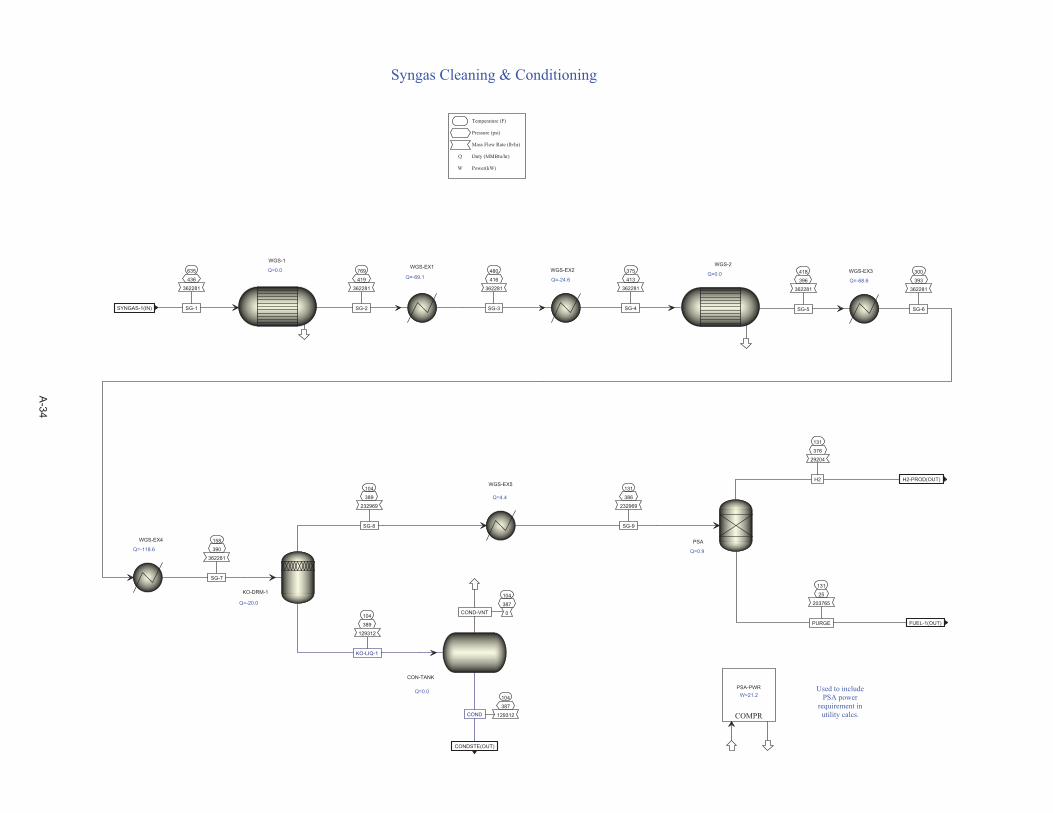
635
436
362281
SG-1SYNGAS-1(IN)
104
387
129312COND
CONDSTE(OUT)
131
25
203765
PURGE FUEL-1(OUT)
131
376
29204
H2 H2-PROD(OUT)
480
416
362281
SG-3
418
396
362281
SG-5
769
419
362281
SG-2
104
389
129312
KO-LIQ-1
104
387
0COND-VNT
300
393
362281
SG-6
104
389
232969
SG-8
WGS-2
Q=0.0WGS-EX1
Q=-69.1
WGS-1
Q=0.0
CON-TANK
Q=0.0
KO-DRM-1
Q=-20.0
WGS-EX3
Q=-68.6
PSA
Q=0.9
COMPR
PSA-PWRW=21.2
Temperature (F)
Pressure (psi)
Mass Flow Rate (lb/hr)
Q Duty (MMBtu/hr)
W Power(kW)
Syngas Cleaning & Conditioning
Used to includePSA power
requirement inutility calcs.
WGS-EX2
Q=-24.6
WGS-EX4
Q=-118.6
375
413
362281
SG-4
158
390
362281
SG-7
WGS-EX5
Q=4.4
131
386
232969
SG-9
A-34
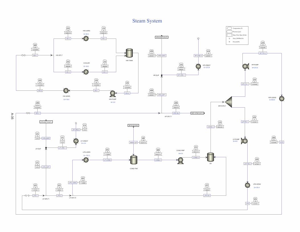
182
15
533415MAKE-UP
BFW-MU2(IN)
307
75
370 LPS-EXP2
LPS-EXPT(OUT)
489
615
266567 HPS-EXP2
HPS-EXPT(OUT)
307
75
15933
LPS-DA
204
21
644313
COND-2
228
21
660246COND-3
228
21
127201LP-FW-1
228
21
533046HP-FW-1
228
75
127201LP-FW-2
204
15
644313
COND-1
229
615
533046
HP-FW-2
489
615
533046
HPS-1
489
615
266478
HPS-INJ REF-STM1(OUT)
489
615
266567 HPS-EXP1
307
75
127201
LPS-1
307
75
126831
LPS-2
307
75
370 LPS-EXP1
307
75
110898LPS-USRS
307
75
110898
LP-COND
489
615
533046 HPS
307
75
127201LPS
307
75
370
LP-CRD-1
489
615
266567
HP-CRD-1
212
15
370LP-CRD-2
212
15
266567HP-CRD-2
DA
BFW-SPLT
LP-PUMPW=9.6
COND-PMP
W=4.6
HP-PUMP
W=370.9
HP-SPLT1
LP-SPLT1LP-SPLT2
LPS-USRS
Q=-100.3
HPS-GENSQ=535.6
LPS-GENS
Q=125.4
LP-DUP
HP-DUP
LP-CREDTQ=-0.4
HP-CREDTQ=-272.8
Temperature (F)
Pressure (psi)
Mass Flow Rate (lb/hr)
Q Duty (MMBtu/hr)
W Power(kW)
Steam System
COND-TNK
200
30
1234595
HW-1
HW-USRS
Q=-80.5
COOLER
Q=-38.0
HW-SPLT
200
30
838516
HW-2
200
30
396080
HW-3
HW-TANK
104
27
838516
HW-4
104
27
396080
HW-5
104
27
1234595
HW-6
HW-PUMP
W=3.9
200
30
1234595
HW-8
HW-GENS
Q=118.6
104
30
1234595
HW-7
A-35

70
15
1082277
AIR-1AIR-CT(IN)
60
15
59195
MU-H2OCT-MU2(IN)
104
15
1129840
AIR-3 CT-EX(OUT)
86
30
11632
BLOWDOWN CT-BD1(OUT)
32
HEAT
122
25
1615599
CWR-1
104
15
1568037
CWS-1
104
15
1129840 AIR-2
86
15
1627232
CWS-3
86
30
1627232
CWS-4
86
30
1615599
CWS-6
86
15
1627232
CWS-2
86
30
1615599
CWS-5
CT-FLASH
Q=32.4
CWS-PUMPW=25.8
CT-FAN
W=25.6
CW-USERS
Q=58.0
CT-COOL
Q=-32.4
BLOWDOWN
COLDWELL
Q=0.0
Temperature (F)
Pressure (psi)
Mass Flow Rate (lb/hr)
Duty (MMBtu/hr)
Q Duty (MMBtu/hr)
W Power(kW)
Cooling Tower
A-36

104
387
117618REF-1
COND-BD2(IN)
86
30
11632COOL-1
CT-BD2(IN)
60
15
557493MKUP-1
MAKEUP(IN)
182
15
533415
TO-HRSGBFW-MU1(OUT)
275
15
94132
EVAP-EXHZLD-EX(OUT)
60
15
59195TO-CT
CT-MU1(OUT)
105
15
117618BIO-EFF
61
15
509930
COOL-2
70
15
533415
RO-EFF
70
15
94132
RO-BD
60
15
498297
MKUP-3
60
15
557493MKUP-2
MIXER
BIOTREAT
FSPLIT
UF-RO
MIXER
POLISH
HEATER
ZLDQ=100.3
MIXER
SOFTEN
MIXER
CLARIFY
COMPR
PWR-CALCW=2440.1
SPLT
Temperature (F)
Pressure (psi)
Mass Flow Rate (lb/hr)
Q Duty (MMBtu/hr)
W Power(kW)
Simplified Water Treatment
PRHT-1
Q=11.4182
15
94132
RO-HOT
PRHT-2
Q=64.770
15
533415
POL-EFF
A-37
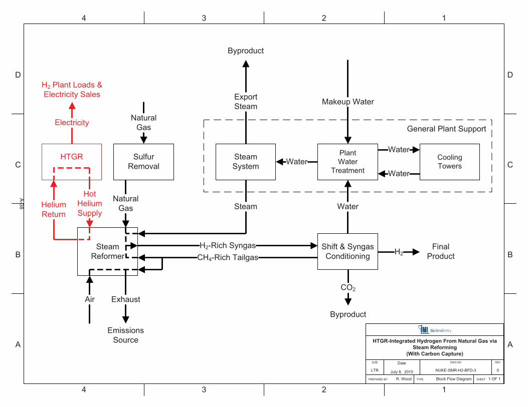
D
C
B
A
4 3 2 1
D
C
B
A
4 3 2 1
Shift & SyngasConditioning
SteamSystem
SteamReformer H2
HTGR-Integrated Hydrogen From Natural Gas via Steam Reforming
(With Carbon Capture)
SHEET 1 OF 1
REV
0
DWG NO
NUKE-SMR-H2-BFD-3
Date
July 8, 2010
PREPARED BY R. Wood
SIZE
LTR
TYPE Block Flow Diagram
H2-Rich Syngas
SulfurRemoval
NaturalGas Steam
NaturalGas
Exhaust
HotHeliumSupply
Water
PlantWater
Treatment
CoolingTowers
Water
WaterWater
Air
FinalProduct
ExportSteam
Byproduct
HeliumReturn
EmissionsSource
HTGR
Electricity
H2 Plant Loads &Electricity Sales
General Plant Support
Makeup Water
CO2
Byproduct
CH4-Rich Tailgas
A-38
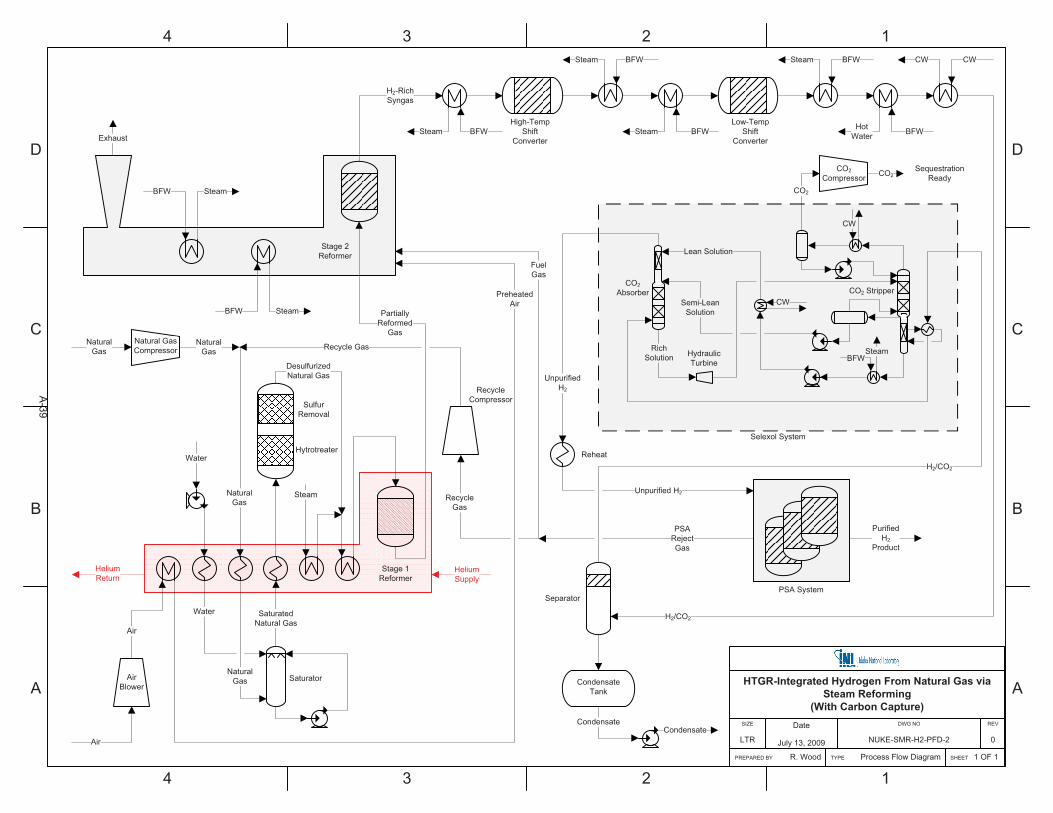
D
C
B
A
4 3 2 1
D
C
B
A
4 3 2 1
HTGR-Integrated Hydrogen From Natural Gas via Steam Reforming
(With Carbon Capture)
SHEET 1 OF 1
REV
0
DWG NO
NUKE-SMR-H2-PFD-2
Date
July 13, 2009
PREPARED BY R. Wood
SIZE
LTR
TYPE Process Flow Diagram
Natural GasCompressor
Stage 1Reformer
PreheatedAir
NaturalGas
Exhaust
Air
BFW
H2-RichSyngas
High-TempShift
Converter
Low-TempShift
Converter
Separator
CondensateCondensate
AirBlower
Air
NaturalGas
Water
Steam
DesulfurizedNatural Gas
Water
SaturatedNatural Gas
NaturalGas
Hytrotreater
SulfurRemoval
Saturator
BFW Steam
BFWSteam
BFWSteam
BFWSteam
BFWHotWater
H2/CO2
CWCW
FuelGas
CondensateTank
Reheat
RecycleCompressor
PurifiedH2
Product
Recycle Gas
Steam
Stage 2Reformer
HeliumReturn
PartiallyReformed
Gas
BFW Steam
HeliumSupply
PSA System
NaturalGas
PSARejectGas
RecycleGas
SequestrationReady
CO2Compressor CO2
CO2Absorber CO2 Stripper
HydraulicTurbine
RichSolution
Semi-LeanSolution
BFWSteam
CW
Lean Solution
CW
Selexol System
CO2
H2/CO2
UnpurifiedH2
Unpurified H2
A-39
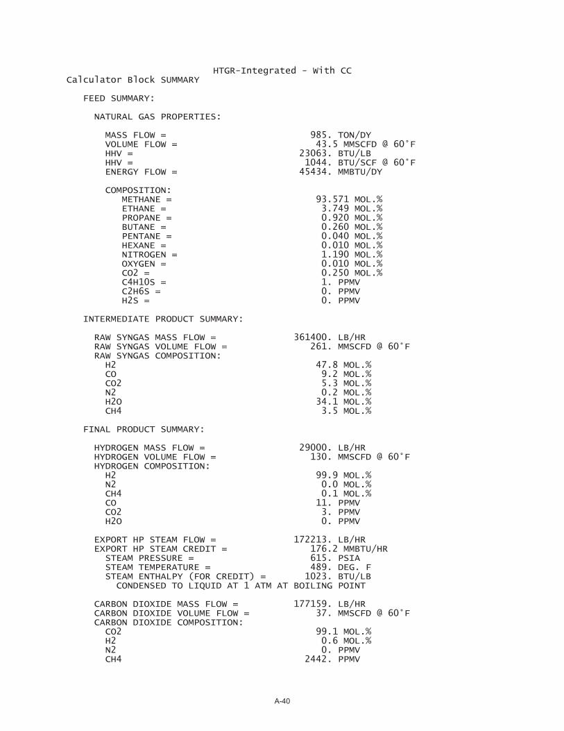
HTGR-Integrated - With CC Calculator Block SUMMARY
FEED SUMMARY:
NATURAL GAS PROPERTIES:
MASS FLOW = 985. TON/DY VOLUME FLOW = 43.5 MMSCFD @ 60°F HHV = 23063. BTU/LB HHV = 1044. BTU/SCF @ 60°F ENERGY FLOW = 45434. MMBTU/DY
COMPOSITION: METHANE = 93.571 MOL.% ETHANE = 3.749 MOL.% PROPANE = 0.920 MOL.% BUTANE = 0.260 MOL.% PENTANE = 0.040 MOL.% HEXANE = 0.010 MOL.% NITROGEN = 1.190 MOL.% OXYGEN = 0.010 MOL.% CO2 = 0.250 MOL.% C4H10S = 1. PPMV C2H6S = 0. PPMV H2S = 0. PPMV
INTERMEDIATE PRODUCT SUMMARY:
RAW SYNGAS MASS FLOW = 361400. LB/HR RAW SYNGAS VOLUME FLOW = 261. MMSCFD @ 60°F RAW SYNGAS COMPOSITION: H2 47.8 MOL.% CO 9.2 MOL.% CO2 5.3 MOL.% N2 0.2 MOL.% H2O 34.1 MOL.% CH4 3.5 MOL.%
FINAL PRODUCT SUMMARY:
HYDROGEN MASS FLOW = 29000. LB/HR HYDROGEN VOLUME FLOW = 130. MMSCFD @ 60°F HYDROGEN COMPOSITION: H2 99.9 MOL.% N2 0.0 MOL.% CH4 0.1 MOL.% CO 11. PPMV CO2 3. PPMV H2O 0. PPMV
EXPORT HP STEAM FLOW = 172213. LB/HR EXPORT HP STEAM CREDIT = 176.2 MMBTU/HR STEAM PRESSURE = 615. PSIA STEAM TEMPERATURE = 489. DEG. F STEAM ENTHALPY (FOR CREDIT) = 1023. BTU/LB CONDENSED TO LIQUID AT 1 ATM AT BOILING POINT
CARBON DIOXIDE MASS FLOW = 177159. LB/HR CARBON DIOXIDE VOLUME FLOW = 37. MMSCFD @ 60°F CARBON DIOXIDE COMPOSITION: CO2 99.1 MOL.% H2 0.6 MOL.% N2 0. PPMV CH4 2442. PPMV
A-40
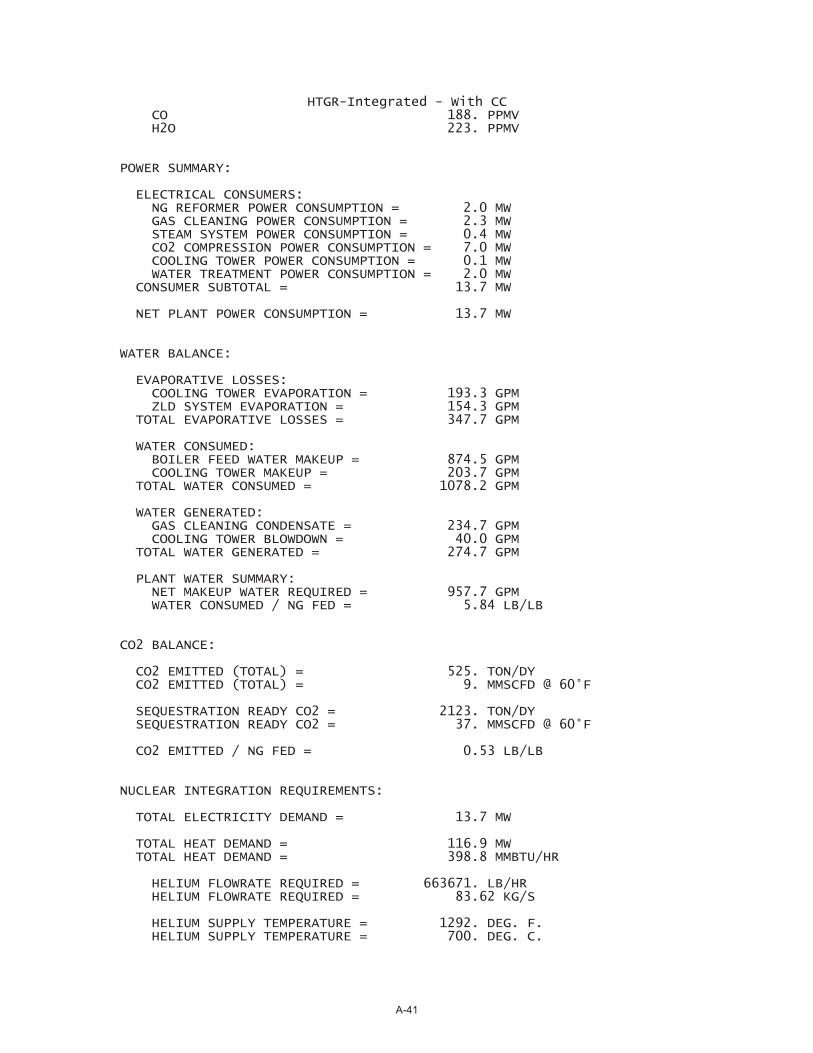
HTGR-Integrated - With CC CO 188. PPMV H2O 223. PPMV
POWER SUMMARY:
ELECTRICAL CONSUMERS: NG REFORMER POWER CONSUMPTION = 2.0 MW GAS CLEANING POWER CONSUMPTION = 2.3 MW STEAM SYSTEM POWER CONSUMPTION = 0.4 MW CO2 COMPRESSION POWER CONSUMPTION = 7.0 MW COOLING TOWER POWER CONSUMPTION = 0.1 MW WATER TREATMENT POWER CONSUMPTION = 2.0 MW CONSUMER SUBTOTAL = 13.7 MW
NET PLANT POWER CONSUMPTION = 13.7 MW
WATER BALANCE:
EVAPORATIVE LOSSES: COOLING TOWER EVAPORATION = 193.3 GPM ZLD SYSTEM EVAPORATION = 154.3 GPM TOTAL EVAPORATIVE LOSSES = 347.7 GPM
WATER CONSUMED: BOILER FEED WATER MAKEUP = 874.5 GPM COOLING TOWER MAKEUP = 203.7 GPM TOTAL WATER CONSUMED = 1078.2 GPM
WATER GENERATED: GAS CLEANING CONDENSATE = 234.7 GPM COOLING TOWER BLOWDOWN = 40.0 GPM TOTAL WATER GENERATED = 274.7 GPM
PLANT WATER SUMMARY: NET MAKEUP WATER REQUIRED = 957.7 GPM WATER CONSUMED / NG FED = 5.84 LB/LB
CO2 BALANCE:
CO2 EMITTED (TOTAL) = 525. TON/DY CO2 EMITTED (TOTAL) = 9. MMSCFD @ 60°F
SEQUESTRATION READY CO2 = 2123. TON/DY SEQUESTRATION READY CO2 = 37. MMSCFD @ 60°F
CO2 EMITTED / NG FED = 0.53 LB/LB
NUCLEAR INTEGRATION REQUIREMENTS:
TOTAL ELECTRICITY DEMAND = 13.7 MW
TOTAL HEAT DEMAND = 116.9 MW TOTAL HEAT DEMAND = 398.8 MMBTU/HR
HELIUM FLOWRATE REQUIRED = 663671. LB/HR HELIUM FLOWRATE REQUIRED = 83.62 KG/S
HELIUM SUPPLY TEMPERATURE = 1292. DEG. F. HELIUM SUPPLY TEMPERATURE = 700. DEG. C.
A-41
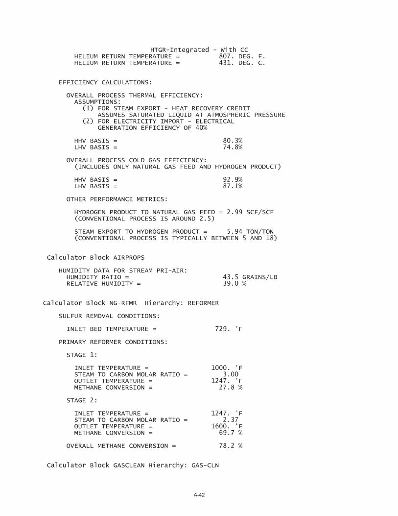
HTGR-Integrated - With CC HELIUM RETURN TEMPERATURE = 807. DEG. F. HELIUM RETURN TEMPERATURE = 431. DEG. C.
EFFICIENCY CALCULATIONS:
OVERALL PROCESS THERMAL EFFICIENCY: ASSUMPTIONS: (1) FOR STEAM EXPORT - HEAT RECOVERY CREDIT ASSUMES SATURATED LIQUID AT ATMOSPHERIC PRESSURE (2) FOR ELECTRICITY IMPORT - ELECTRICAL GENERATION EFFICIENCY OF 40%
HHV BASIS = 80.3% LHV BASIS = 74.8%
OVERALL PROCESS COLD GAS EFFICIENCY: (INCLUDES ONLY NATURAL GAS FEED AND HYDROGEN PRODUCT)
HHV BASIS = 92.9% LHV BASIS = 87.1%
OTHER PERFORMANCE METRICS:
HYDROGEN PRODUCT TO NATURAL GAS FEED = 2.99 SCF/SCF (CONVENTIONAL PROCESS IS AROUND 2.5)
STEAM EXPORT TO HYDROGEN PRODUCT = 5.94 TON/TON (CONVENTIONAL PROCESS IS TYPICALLY BETWEEN 5 AND 18)
Calculator Block AIRPROPS
HUMIDITY DATA FOR STREAM PRI-AIR: HUMIDITY RATIO = 43.5 GRAINS/LB RELATIVE HUMIDITY = 39.0 %
Calculator Block NG-RFMR Hierarchy: REFORMER
SULFUR REMOVAL CONDITIONS:
INLET BED TEMPERATURE = 729. °F
PRIMARY REFORMER CONDITIONS:
STAGE 1:
INLET TEMPERATURE = 1000. °F STEAM TO CARBON MOLAR RATIO = 3.00 OUTLET TEMPERATURE = 1247. °F METHANE CONVERSION = 27.8 %
STAGE 2:
INLET TEMPERATURE = 1247. °F STEAM TO CARBON MOLAR RATIO = 2.37 OUTLET TEMPERATURE = 1600. °F METHANE CONVERSION = 69.7 %
OVERALL METHANE CONVERSION = 78.2 %
Calculator Block GASCLEAN Hierarchy: GAS-CLN
A-42
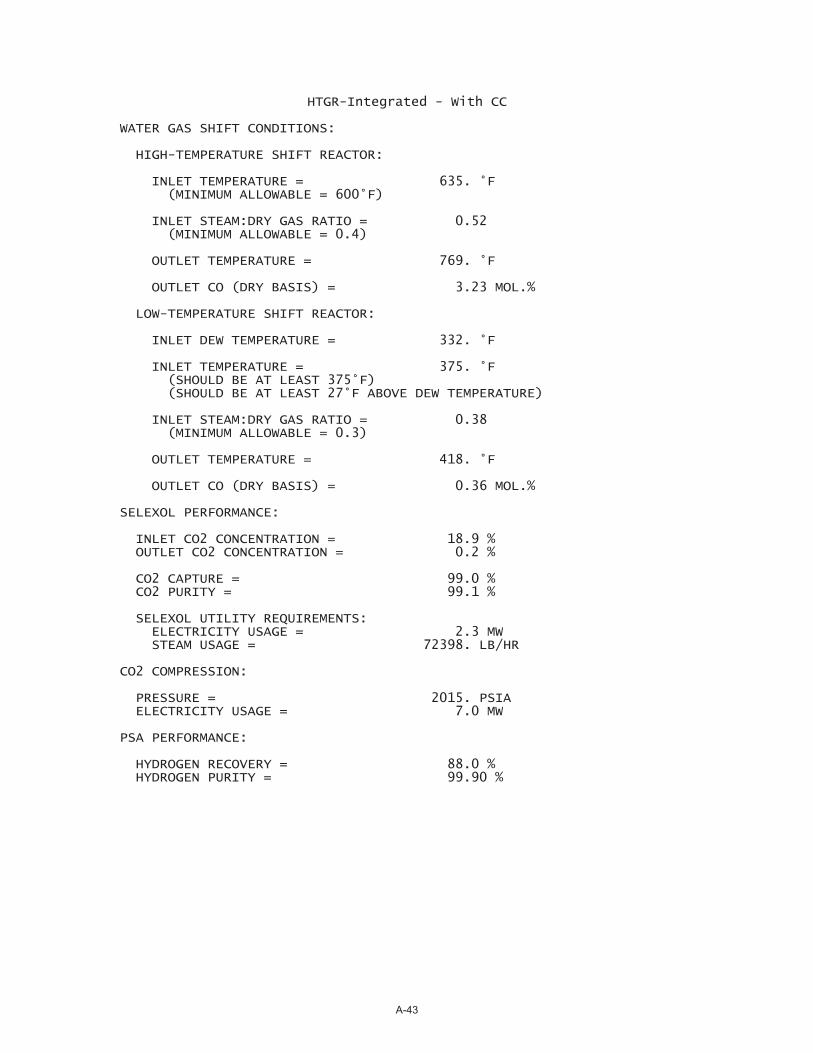
HTGR-Integrated - With CC
WATER GAS SHIFT CONDITIONS:
HIGH-TEMPERATURE SHIFT REACTOR:
INLET TEMPERATURE = 635. °F (MINIMUM ALLOWABLE = 600°F)
INLET STEAM:DRY GAS RATIO = 0.52 (MINIMUM ALLOWABLE = 0.4)
OUTLET TEMPERATURE = 769. °F
OUTLET CO (DRY BASIS) = 3.23 MOL.%
LOW-TEMPERATURE SHIFT REACTOR:
INLET DEW TEMPERATURE = 332. °F
INLET TEMPERATURE = 375. °F (SHOULD BE AT LEAST 375°F) (SHOULD BE AT LEAST 27°F ABOVE DEW TEMPERATURE)
INLET STEAM:DRY GAS RATIO = 0.38 (MINIMUM ALLOWABLE = 0.3)
OUTLET TEMPERATURE = 418. °F
OUTLET CO (DRY BASIS) = 0.36 MOL.%
SELEXOL PERFORMANCE:
INLET CO2 CONCENTRATION = 18.9 % OUTLET CO2 CONCENTRATION = 0.2 %
CO2 CAPTURE = 99.0 % CO2 PURITY = 99.1 %
SELEXOL UTILITY REQUIREMENTS: ELECTRICITY USAGE = 2.3 MW STEAM USAGE = 72398. LB/HR
CO2 COMPRESSION:
PRESSURE = 2015. PSIA ELECTRICITY USAGE = 7.0 MW
PSA PERFORMANCE:
HYDROGEN RECOVERY = 88.0 % HYDROGEN PURITY = 99.90 %
A-43
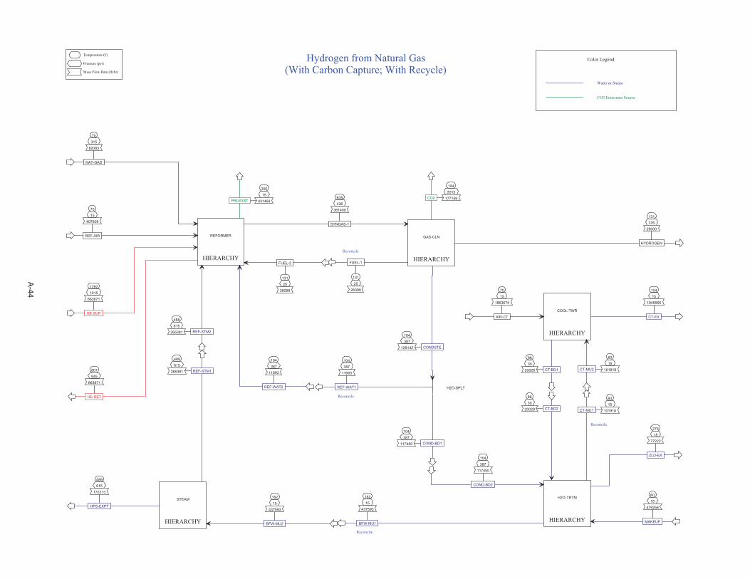
HIERARCHY
COOL-TWR
HIERARCHY
GAS-CLN
HIERARCHY
H2O-TRTM
HIERARCHY
REFORMER
HIERARCHY
STEAM
70
15
1863674
AIR-CT
60
15
101918CT-MU2
104
15
1945565
CT-EX
86
30
20028 CT-BD1
635
436
361400
SYNGAS-1
104
387
129142 CONDSTE
131
25
26099
FUEL-1
104
387
117450
COND-BD2
86
30
20028 CT-BD2
60
15
479256
MAKEUP
182
15
437593
BFW-MU1
275
15
77222
ZLD-EX
60
15
101918CT-MU1
488
615
265381 REF-STM2
70
15
407609
REF-AIR
104
387
11693
REF-WAT2
70
315
82083
NAT-GAS
131
25
26099
FUEL-2
300
15
431464PRI-EXST
182
15
437593
BFW-MU2
489
615
172213
HPS-EXPT
104
387
11693
REF-WAT1
104
387
117450 COND-BD1
131
376
29000
HYDROGEN
H2O-SPLT
Temperature (F)
Pressure (psi)
Mass Flow Rate (lb/hr)
Hydrogen from Natural Gas(With Carbon Capture; With Recycle)
Reconcile
Water or Steam
CO2 Emissions Source
Color Legend
Reconcile
Reconcile
Reconcile
489
615
265381 REF-STM1
184
2015
177159CO2
1292
1015
663671
HE-SUP
807
945
663671
HE-RET
A-44
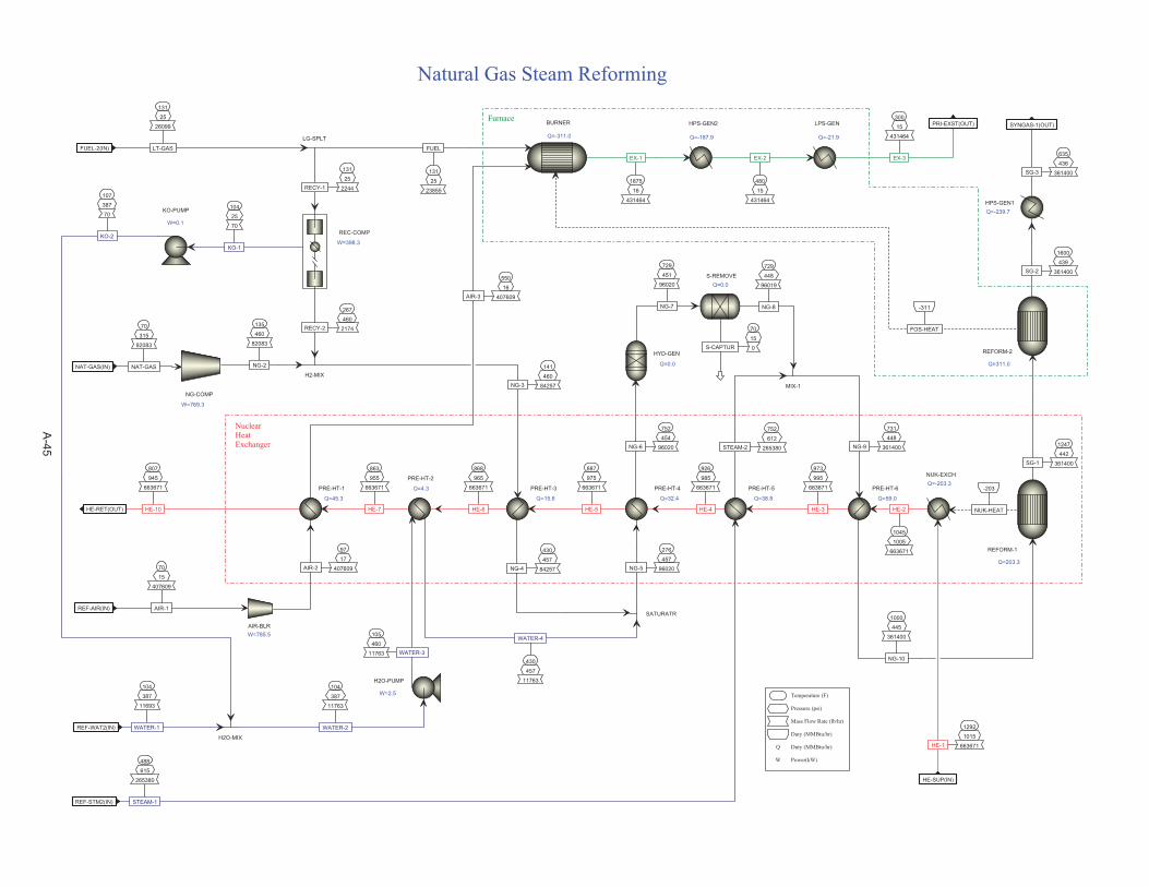
887
975
663671
HE-5
141
460
84257NG-3
430
457
84257NG-4
868
965
663671
HE-6
752
454
96020NG-6
729
451
96020
NG-7
70
15
0S-CAPTUR
729
448
96019
NG-8
430
457
11763
WATER-4
276
457
96020NG-5
926
985
663671
HE-4
752
612
265380STEAM-2
731
448
361400NG-9
1045
1005
663671
HE-2
1000
445
361400
NG-10
973
995
663671
HE-3
1247
442
361400SG-1
-203
NUK-HEAT
550
16
407609AIR-3
131
25
26099
LT-GASFUEL-2(IN)
-311
FOS-HEAT
1875
16
431464
EX-1
70
15
407609
AIR-1REF-AIR(IN)
97
17
407609AIR-2
104
387
11693
WATER-1REF-WAT2(IN)
105
460
11763 WATER-3
70
315
82083
NAT-GASNAT-GAS(IN)
135
460
82083
NG-2
1600
439
361400SG-2
635
436
361400SG-3
SYNGAS-1(OUT)
863
955
663671
HE-7
488
615
265380
STEAM-1REF-STM2(IN)
807
945
663671
HE-10HE-RET(OUT)
480
15
431464
EX-2
300
15
431464
EX-3
PRI-EXST(OUT)
1292
1015
663671HE-1
HE-SUP(IN)
PRE-HT-3
Q=15.6
HYD-GEN
Q=0.0
S-REMOVEQ=0.0
SATURATR
PRE-HT-4
Q=32.4
MIX-1
PRE-HT-6
Q=59.0
REFORM-1
Q=203.3
BURNER
Q=-311.0
AIR-BLRW=785.5
H2O-PUMP
W=2.5
NG-COMP
W=769.3
HPS-GEN1Q=-239.7
PRE-HT-2
Q=4.3 PRE-HT-5
Q=38.8
PRE-HT-1
Q=45.3
H2-MIX
HPS-GEN2
Q=-187.9
LPS-GEN
Q=-21.9
REFORM-2
Q=311.0
NUK-EXCHQ=-203.3
Temperature (F)
Pressure (psi)
Mass Flow Rate (lb/hr)
Duty (MMBtu/hr)
Q Duty (MMBtu/hr)
W Power(kW)
Natural Gas Steam Reforming
NuclearHeatExchanger
Furnace
267
460
2174RECY-2
131
25
2244RECY-1
LG-SPLT
131
25
23855
FUEL
REC-COMP
W=398.3
104
25
70
KO-1
KO-PUMP
W=0.1
107
387
70
KO-2
H2O-MIX
104
387
11763
WATER-2
A-45
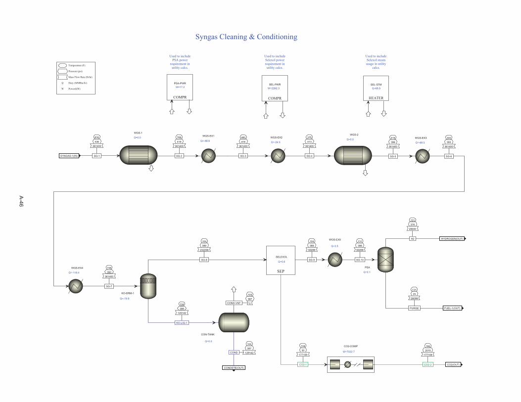
635
436
361400
SG-1SYNGAS-1(IN)
104
387
129142COND
CONDSTE(OUT)
131
25
26099
PURGE FUEL-1(OUT)
131
376
29000
H2 HYDROGEN(OUT)
480
416
361400
SG-3
418
396
361400
SG-5
769
419
361400
SG-2
104
389
129142
KO-LIQ-1
104
387
0COND-VNT
300
393
361400
SG-6
104
389
55099
SG-9
WGS-2
Q=0.0WGS-EX1
Q=-68.9
WGS-1
Q=0.0
CON-TANK
Q=0.0
KO-DRM-1
Q=-19.9
WGS-EX3
Q=-68.5
PSA
Q=0.1
COMPR
PSA-PWRW=17.2
Temperature (F)
Pressure (psi)
Mass Flow Rate (lb/hr)
Q Duty (MMBtu/hr)
W Power(kW)
Syngas Cleaning & Conditioning
Used to includePSA power
requirement inutility calcs.
WGS-EX2
Q=-24.5
WGS-EX4
Q=-118.4
375
413
361400
SG-4
158
390
361400
SG-7
WGS-EX5
Q=3.5
131
386
55099
SG-10
104
30
177159
CO2-1
184
2015
177159
CO2-2 CO2(OUT)
CO2-COMP
W=7022.7
SEP
SELEXOL
Q=0.6
104
389
232258
SG-8
HEATER
SEL-STMQ=65.5
COMPR
SEL-PWRW=2262.3
Used to includeSelexol powerrequirement inutility calcs.
Used to includeSelexol steamusage in utility
calcs.
A-46
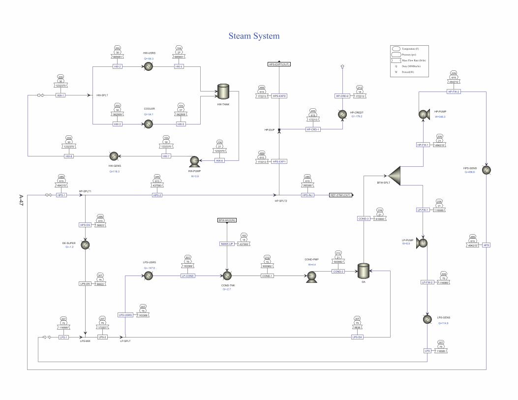
182
15
437593MAKE-UP
BFW-MU2(IN)
489
615
172213 HPS-EXP2
HPS-EXPT(OUT)
307
75
9838
LPS-DA
212
21
600962
COND-2
228
21
610800COND-3
228
21
116585LP-FW-1
228
21
494215HP-FW-1
228
75
116585LP-FW-2
229
615
494215
HP-FW-2
489
615
494215
HPS-1
489
615
265380
HPS-INJ REF-STM1(OUT)
489
615
172213 HPS-EXP1
307
75
116585
LPS-1
489
615
437593
HPS-2
489
615
56622HPS-DS
307
75
163369LPS-USRS
307
75
163369
LP-COND
489
615
494215 HPS
307
75
116585LPS
489
615
172213
HP-CRD-1
212
15
172213HP-CRD-2
DA
BFW-SPLT
LP-PUMPW=8.9
COND-PMP
W=4.4
HP-PUMP
W=346.3
HP-SPLT2
HP-SPLT1
LP-SPLT
LPS-USRS
Q=-147.8
HPS-GENSQ=496.6
LPS-GENS
Q=114.9
HP-DUP
HP-CREDTQ=-176.2
Temperature (F)
Pressure (psi)
Mass Flow Rate (lb/hr)
Q Duty (MMBtu/hr)
W Power(kW)
Steam System
200
30
1232370
HW-1
HW-USRS
Q=-64.3
COOLER
Q=-54.1
HW-SPLT
200
30
669461
HW-2
200
30
562909
HW-3
HW-TANK
104
27
669461
HW-4
104
27
562909
HW-5
104
27
1232370
HW-6
HW-PUMP
W=3.9
200
30
1232370
HW-8
HW-GENS
Q=118.3
104
30
1232370
HW-7
DE-SUPERQ=-1.2
307
75
56622LPS-DS
LPS-MIX
307
75
173207
LPS-2
COND-TNKQ=-2.7
212
15
600962
COND-1
A-47

70
15
1863675
AIR-1AIR-CT(IN)
60
15
101917
MU-H2OCT-MU2(IN)
104
15
1945565
AIR-3 CT-EX(OUT)
86
30
20028
BLOWDOWN CT-BD1(OUT)
56
HEAT
122
25
2781623
CWR-1
104
15
2699733
CWS-1
104
15
1945565 AIR-2
86
15
2801651
CWS-3
86
30
2801651
CWS-4
86
30
2781623
CWS-6
86
15
2801651
CWS-2
86
30
2781623
CWS-5
CT-FLASH
Q=55.8
CWS-PUMPW=43.5
CT-FAN
W=44.1
CW-USERS
Q=99.9
CT-COOL
Q=-55.8
BLOWDOWN
COLDWELL
Q=0.0
Temperature (F)
Pressure (psi)
Mass Flow Rate (lb/hr)
Duty (MMBtu/hr)
Q Duty (MMBtu/hr)
W Power(kW)
Cooling Tower
A-48

104
387
117449REF-1
COND-BD2(IN)
86
30
20028COOL-1
CT-BD2(IN)
60
15
479256MKUP-1
MAKEUP(IN)
182
15
437593
TO-HRSGBFW-MU1(OUT)
275
15
77222
EVAP-EXHZLD-EX(OUT)
60
15
101917TO-CT
CT-MU1(OUT)
105
15
117449BIO-EFF
63
15
397367
COOL-2
73
15
437593
RO-EFF
73
15
77222
RO-BD
60
15
377339
MKUP-3
60
15
479256MKUP-2
MIXER
BIOTREAT
FSPLIT
UF-RO
MIXER
POLISH
HEATER
ZLDQ=82.3
MIXER
SOFTEN
MIXER
CLARIFY
COMPR
PWR-CALCW=2023.7
SPLT
Temperature (F)
Pressure (psi)
Mass Flow Rate (lb/hr)
Q Duty (MMBtu/hr)
W Power(kW)
Simplified Water Treatment
PRHT-1
Q=9.1182
15
77222
RO-HOT
PRHT-2
Q=51.773
15
437593
POL-EFF
A-49