Embed Size (px)
DESCRIPTION
http://pwp.co.nz/downloads/2901-CortexManual_V7.pdf
Citation preview
Technical ManualTechnical ManualA Natural Advance in Cladding
The mark ofresponsible forestry
SGS-COC-0889© 1996 Forest Stewardship Council A.C.
Contents1 Introduction & Scope 3
1.1 Scope 3
1.2 Details 3
2 Design & Specifi cation 3
2.1 Compliance 3
2.2 Responsibility 3
2.3 Site & Foundation 3
2.4 Wind Loading 3
2.5 Paint Selection 3
3 Installation Sequence 5
3.1 General 6
3.2 Framing 6
3.3 Building Wrap 6
3.4 Drained & Vented Cavity 6
3.4.1 Cavity Closer Installation 6
3.4.2 Cavity Batten Installation 7
3.5 The Concealed Fixing System 7
3.6 Vertical Joins 7
3.7 Corners 7
3.8 Ends and Material Transitions 8
3.9 Windows, Doors & Meter Box 8
3.10 Junctions & Penetrations 8
3.11 Finishing 8
4 Maintenance 9
4.1 Washing 9
4.2 Re-Paint 9
4.3 Touch-up Painting 9
4.4 Replacement of damaged weatherboards 9
5 Warranty 10
6 Cortex Parts & Accessories 11
7 Installation Details 12
7.1 Cavity 12
We Value Your Feedback
To continue with the development of our products and systems, we value your input. Please send any suggestions, including your name, contact details, and relevant sketches to:
Fax 0800 808 [email protected]
Introduction1 & Scope
Cortex is a solid timber weatherboard cladding system with a full factory applied top coat fi nish, it evolves this traditional product through the addition of new detailing and fi xing methods. The Cortex system comes complete with all accessories including corner extrusions, scribers, cavity closers and fl ashings to make specifi cation building and use a breeze.
The Cortex 100% factory fi nished weatherboard Acrylic Coating System™ (ACS) delivers a consistent 120 microns ‘dry’ fi lm thickness to the exposed surfaces of each board. This ensures each board delivers lasting performance across its lifespan. The ACS fi nish delivers a good looking, smooth fi nish that manual application can’t match.
Specifi ers
This manual is designed to provide all the information required for the planning and specifying process. Please ensure that the project you are planning falls within the scope of this manual and don’t hesitate to contact Cortex if you have any queries.
Builders & Installers
This manual will provide all the information necessary for correct installation of the Cortex cladding system. The characteristics of the pre-fi nished board require careful handling and a range of proprietary fi xings and fl ashings to be used, therefore we urge you to adhere to the specifi ed installation sequence to ensure correct installation. Please contact Cortex if you have any queries.
The Cortex Technical Manual is available for download from our website; please ensure that you have the most up-to-date manual. If you are unsure, please check the website or call us on 0800 CORTEX.
Scope1.1
Please Note: This manual only covers the installation of the Cortex System on a drained and vented cavity.
Cortex has been designed to be specifi ed for domestic timber framed and light commercial buildings that fall within the scope of NZS 3604 and NZBC Acceptable Solution E2/AS1.
The Cortex System is a complete cladding solution and should be specifi ed and installed according the details in this technical manual. Due to the pre-fi nished nature of the product only Cortex specifi ed parts and accessories are to be used with the system, replacement or use of non-cortex fl ashings and accessories will invalidate the warranty.
Details 1.2 All key installation details are provided at the end of this manual. These can also be downloaded directly from www.cortexcladding.co.nz. Please ensure that you are using the most up-to-date details. If you are unsure, please check the website or give us a call on 0800 CORTEX.
Design 2 & Specification
Compliance2.1 The Cortex System has been successfully tested to the requirements of E2/VM1 and meets the performance requirements of the NZBC E2/AS1. This test was conducted by an IASNZ accredited testing laboratory at BRANZ.
Responsibility2.2 These specifi cations are specifi c to the installation of the Cortex System as a complete cladding solution and must be read in conjunction with the accompanying installation details and CAD fi les.
The specifi er must apply this specifi cation to each individual project, ensuring that the details in this specifi cation are suitable for the intended application and that additional detailing and specifi c designs are produced where required.
The certifi ed Cortex installer will install the system according to the details provided in this specifi cation. For situations where details are not provided, please refer to NZBC E2/AS1.
Wind Loading2.3 The Cortex System may be used as exterior cladding in NZS 3604 type constructions for all wind zones up to and including “Very High”. The E2/VM1 weather-tightness testing verifi es the systems performance up to a design differential ultimate limit state wind pressure of 2.5 kPa. The structural design of buildings situated in areas with a design wind speed of greater than 50 m/s (Very High) require specifi c engineering design. This also applies to window joinery.
Paint Selection2.4 The Cortex weatherboards are pre-fi nished with our factory applied Acrylic Coating System™ (ACS). Pre-fi nishing does not mean restrictions in choice; the entire Resene colour range is available from which to choose a suitable shade. However, to ensure that the coating will last we recommend that the colour chosen has a Light Refl ectance Value (LRV) between 40-100%. If a colour with a lower LRV is specifi ed the durability of the coating cannot be guaranteed by Cortex and the 10 year warranty for the coating would not apply.
A sample of the specifi ed colour will be sent to the customer for fi nal sign-off three weeks from production. For guidance on safe, durable colours please contact Cortex or visit us at www.cortexcladding.co.nz for further details.
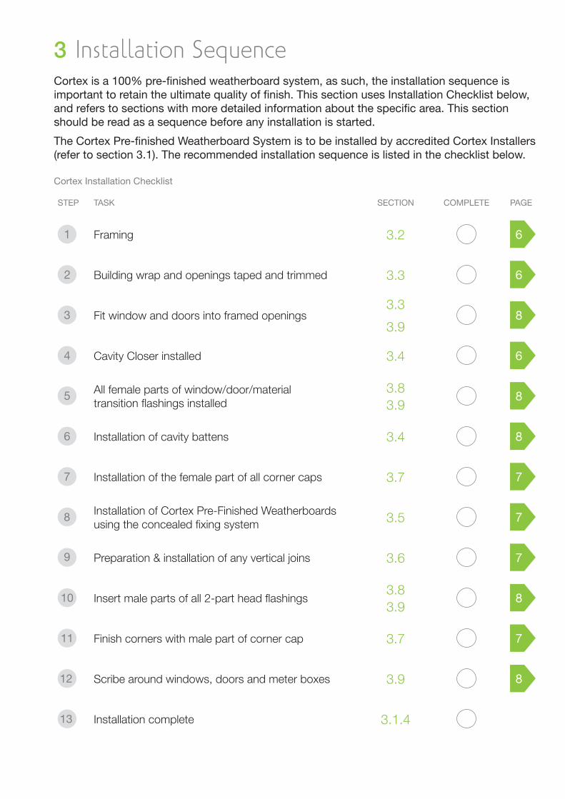
Installation Sequence3 Cortex is a 100% pre-fi nished weatherboard system, as such, the installation sequence is important to retain the ultimate quality of fi nish. This section uses Installation Checklist below, and refers to sections with more detailed information about the specifi c area. This section should be read as a sequence before any installation is started.
The Cortex Pre-fi nished Weatherboard System is to be installed by accredited Cortex Installers (refer to section 3.1). The recommended installation sequence is listed in the checklist below.
Cortex Installation Checklist
STEP TASK SECTION COMPLETE PAGE
Framing 3.2 6
Building wrap and openings taped and trimmed 3.3 6
Fit window and doors into framed openings3.3
3.98
Cavity Closer installed 3.4 6
All female parts of window/door/material transition fl ashings installed
3.83.9
8
Installation of cavity battens 3.4 8
Installation of the female part of all corner caps 3.7 7
8 Installation of Cortex Pre-Finished Weatherboards using the concealed fi xing system 3.5 7
9 Preparation & installation of any vertical joins 3.6 7
10 Insert male parts of all 2-part head fl ashings3.83.9
8
11 Finish corners with male part of corner cap 3.7 7
12 Scribe around windows, doors and meter boxes 3.9 8
13 Installation complete 3.1.4
General3.1 The Cortex Cladding System is broadly protected through Patent and Trademark in New Zealand and Internationally. NZ Pat Appln No. 564490 / PCT Pat Appln No. PCT/NZ2007/000372
The Installation Service3.1.1 The Cortex System is a fully integrated cladding solution that manages the process from specifi cation to completion, including the installation. Cortex is installed by an certifi ed team that is trained to install the Cortex System according to the specifi cations and guidelines in this specifi cation. For more information about the installation service, please contact Cortex directly or visit our website.
Transportation of Pre-Finished Boards & 3.1.2 AccessoriesAll Cortex weatherboards are transported in a specially designed packaging system. This ensures that the pre-fi nished paint surface is protected from any potential damage during transit.
To unload the weatherboards from the truck, use a mechanical lifting device or unload the package containing the board by hand. Do not tip the boards from the truck.
Storage on-site3.1.3 The boards should be kept in their original packaging on-site until the time of installation; the boards should only be removed from their packaging when they are being installed. When stored the Cortex pre-fi nished boards should be protected from unnecessary exposure to rain and sun. It is recommended that the board packages are Stored under cover.
Handling of Pre-Finished Boards & 3.1.4 AccessoriesThe packaging will, in addition to the pre-fi nished boards, also contain the pre-fi nished corner caps, head fl ashings and scribers. Care must be taken when handling the pre-fi nished material to avoid any damage to the surfaces. Carry boards with their long section vertical to avoid bending of the board.
Do not place the board with the pre-fi nished face down, and do not stack the boards on top of each other as this can cause paint blocking.
Never use a hammer in contact with the pre-fi nished exposed surface.
Framing 3.2 This specifi cation only covers the use of timber-framed buildings. Other framing materials are outside the scope of the Cortex Technical Specifi cation Manual.
All framing must comply with the requirements of NZS 3604 Timber Framed Buildings. Specifi cally;
The framing must be straight and true and within the tolerances allowed by Table 2.1 of NZS 3604
The moisture content of the framing must not exceed 20%
All framing sizes and set out must comply with NZS 3604 and studs, nogs/dwangs centred as required for cavity construction.
Windows and meter box openings must be framed to give a 7.5mm minimum clearance between the reveal or window frame and the trimmed opening.
Buildings or parts of buildings outside the scope of NZS 3604 must be to a specifi c design in accordance with NZS 3603 and AS/NZS 1170. Where specifi c design is required, the framing must be of at least equivalent stiffness to the framing provisions of NZS 3604. In all cases studs must be at maximum 600 mm centres and dwangs must be fi tted fl ush between the studs at maximum 800 mm centres.
Building Wrap3.3 Building Wrap compliant with the NZBC Acceptable Solution E2/AS1 must be installed to the outer face of the wall framing. A wall wrap (including building papers and synthetic wall wraps) as per Table 23 Cavity Wall are suitable for use with the Cortex System.
The building wrap must be fi xed in accordance with E2/AS1and the wrap manufacturer’s recommendations:
Run the building wrap horizontally and continuously around corners, do not join material around corners. Install the wrap taut and without any wrinkles.
Have upper sheets lapped over lower sheets to ensure that direction of laps will allow water to be shed to the outside of the building wrap.
Overlap the wrap with a minimum of 75 mm at horizontal joints.
Overlap the wrap with a minimum of 150 mm over studs at vertical joints.
Fix wrap according to manufacturer’s specifi cation.
Dress wrap into all framed openings, including window, door, and meter box openings. Apply a compatible fl exible fl ashing tape around the window and door joinery opening in accordance with the requirements of E2/AS1 and the manufacturer’s instructions.
Drained & Vented Cavity3.4
Please note: The Cortex System is currently only to be specifi ed with a drained and vented cavity.
Cavity Design & Material3.4.1
MATERIALS FIXINGS
Cortex 20mm Cavity Batten TBA (nail)
Cortex Cavity Closer 8Gx50mm self tapping screw
A drained and vented cavity is created by fi xing the Cortex Cavity Batten over the framing in accordance with the requirements of the E2/AS1. The cavity is vermin proofed using the Cortex Cavity Closer with a minimum ventilation area of 1000m2 per lineal metre.
The cavity must be drained and open to the exterior at the bottom of cavities such as at the bottom of the second storey junction and at the top of windows, doors, meter boxes and other penetrations.
Where penetrations of the wall cladding are wider than the cavity batten spacing, allowance shall be made for air fl ow between adjacent cavities by leaving a minimum gap of 10 mm between the bottom of the vertical cavity batten and the fl ashing at the opening.
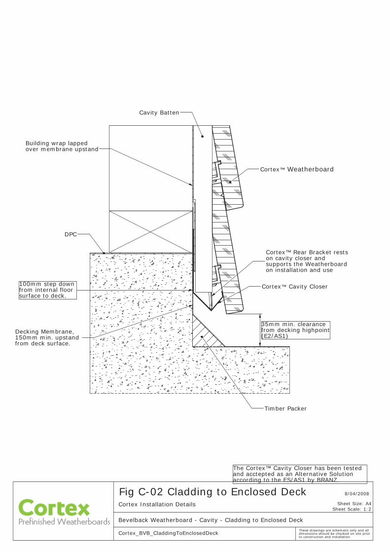
Cavity Closer Installation (Critical Detail)3.4.2 The Cortex Cavity Closer is specially designed to interact with the Cortex Rear Bracket and also aligns the system. The bottom Weatherboard and Rear Bracket assembly of the wall rests on the cavity closer. Install the cavity closer before installing the cavity battens and this makes alignment of the cavity closer easier.
It is therefore imperative that the cavity closer is installed in level, to ensure a level and true installation of the weatherboards. A laser level should be used to align the cavity closer.
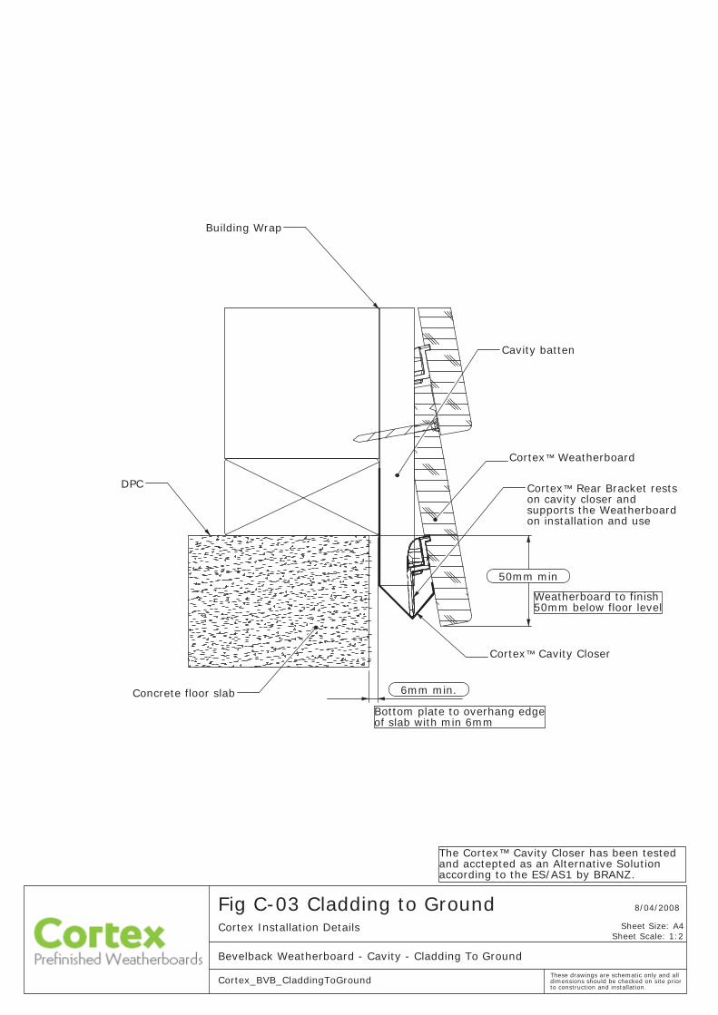
Align the cavity closer to provide a minimum of 50mm overhang of the bottom weatherboard to the interior fl oor. Where possible position so that multiples of the 110mm pitch fi nish at the at the soffi t.
Terminate the cavity closer 25mm from either side of a corner (both internal and external) to allow suffi cient room for corner fl ashings.
The ventilation holes on the cavity closer must be kept clear and unobstructed to allow free drainage and ventilation of cavities.
Refer to installation detail C-03 Cladding to Ground
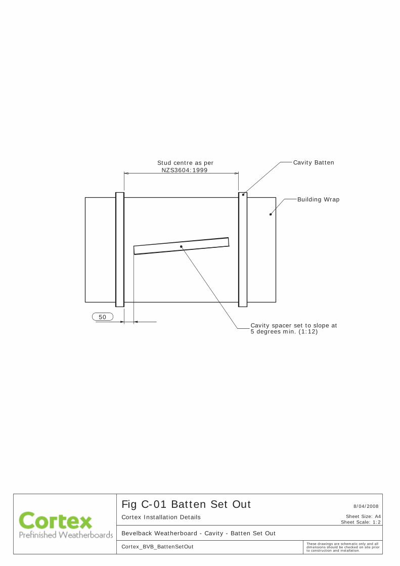
Cavity Batten Installation3.4.3
Please Note: The Cortex Cavity Closer, female part of Cortex 2-part Head fl ashing and female part of Material Transition/End Cap must be installed before installing the cavity battens.
Ensure that the cavity closer and the female part of Cortex 2-part Head Flashing and the female part of Material Transition/End Cap are installed prior to installing the cavity battens.
Fix Cortex Cavity Batten onto all vertical framing members over the building wrap. Battens are to be fi xed by the cladding fi xings which penetrate the wall framing. Battens will therefore need only temporary fi xing until the cladding is fi xed.
When the cavity battens are installed at greater than 450 mm centres, the building wrap must be supported between the battens to prevent the wrap bulging into the cavity space when bulk insulation is installed in the wall frame cavity.
Fix vertical cavity battens past the ends of the head fl ashings to form stop ends for the fl ashings.
There must be no continuous horizontal battens below windows.
> Refer to installation detail C-01 Batten Set Out
The Concealed Fixing System3.5 NZ Pat Appln No. 564490 / PCT Pat Appln No. PCT/NZ2007/000372
MATERIALS FIXINGS
Cortex Rear Bracket 6Gx25mm gypsum screw
Cortex Bevelback Weatherboard
8Gx50mm self tapping screw
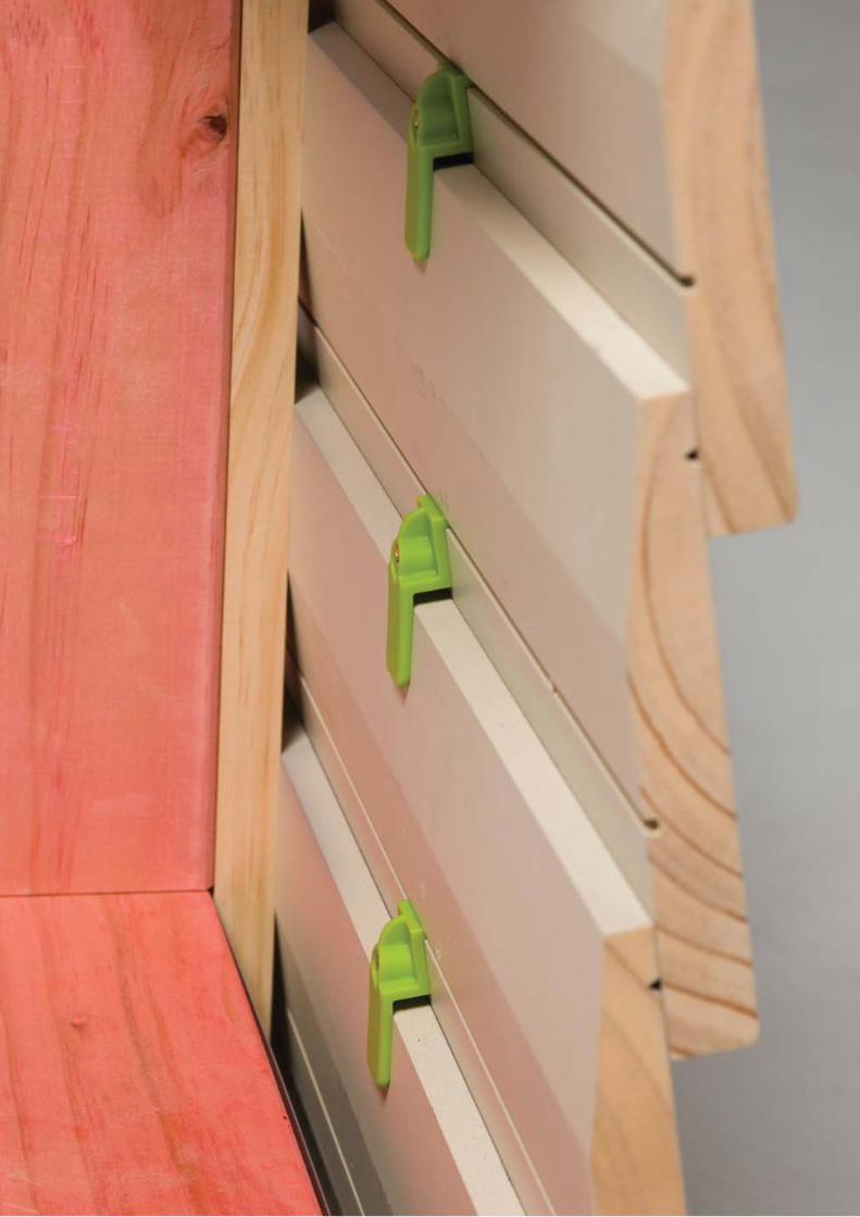
The concealed fi xing system is unique to Cortex and eliminates any exposed penetrations of the pre-fi nished board ensuring that the fi nish retains its integrity.
The screws and brackets combine to offer better board-to-board assembly and installation, whilst the 300mm spaced diamond fi xing pattern dramatically increases strength and wind resistance over existing nailed systems.
Pre-assemble the Rear Brackets to the pre-machined weatherboard using a 6Gx25mm Gypsum Screw. Position the rear brackets to be centred between studs, it is recommended to use a story stick to simplify the process.
When cutting the boards to length, ensure that they are cut to the correct alignment groove on the female corner extrusion. End seal all cut ends with cortex approved wood primer.
Refer to installation details C-04 External Corners or C-05 Internal Corners
Use the Cortex Alignment Tool to ensure that each board is installed with a consistent overlap and a board pitch of 110mm. Push tool hard up against the base of the top weatherboard and adjust the new board to suit. Care must be taken in properly spacing the boards as any discrepancies will interfere with the pre-made Cortex Timber Scriber.
Once the board is in place, fasten the top of the new weatherboard to the stud through the cavity batten with an 8Gx50mm Self Tapping Screw. Pre-drilling of the screw holes is recommended. The fastener should be placed at least 10mm in from the edge of the board to avoid splitting.
Refer to installation detail Fig C-06 a,b,c,d
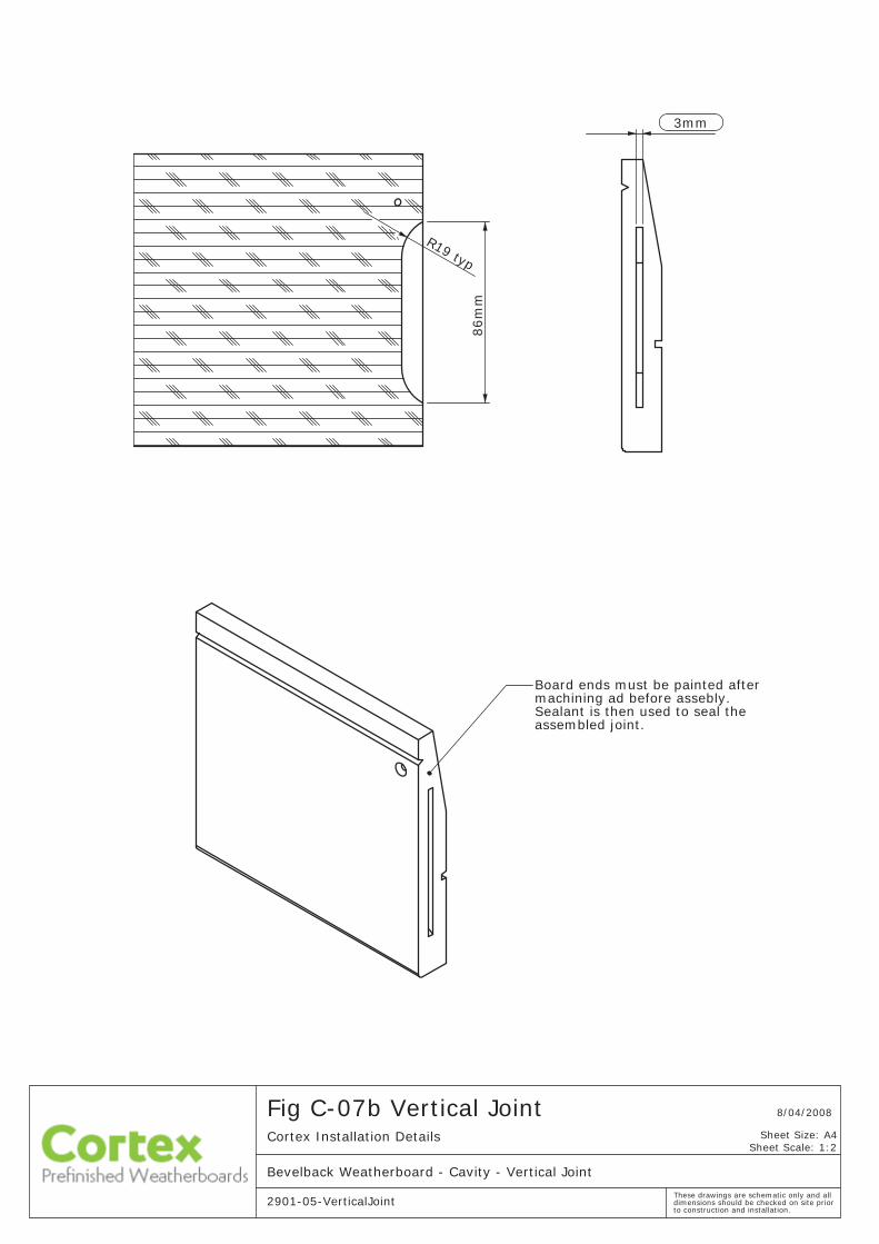
Vertical Joins3.6
MATERIALS FIXINGS
Cortex Vertical Joint Strip Sealant
Cortex Weatherboardwith end cut
8Gx50mm self tapping screw
Cortex Rear Bracket 6Gx25mm gypsum screw
Fix the weatherboard in full wall lengths were possible. Where unavoidable, commit vertical joints only over a stud to ensure a stable joint.
The joint is secured with the Cortex Vertical Joint Strip; a polypropylene barbed joint strip that joins the ends of the boards to protect against moisture ingress. This will require two rear brackets on either side of the joint to provide stability and strength.
The vertical joint strip fi ts into a pre-machined slot on the edge of the weatherboards. The required number of boards with
pre-machined slots will be supplied with each job lot. The ends are pre-fi nished and do not require any further edge seal. Ensure that these are identifi ed and chosen for the vertical joint installation.
Create a sub-assembly by inserting the Cortex Vertical Joint Strip into the slot in one board and seal with the specifi ed sealant. Assemble a rear bracket to the board, positioned as close to the stud as possible.
Install the board sub-assembly on the wall and fasten the top of board onto the stud with a 8Gx50mm Self Tapping Screw.
Prepare the next board with sealant in the slot and fasten the rear bracket to the board as close to the stud as possible. Align the slot with Cortex Vertical Joint Strip and tap the board into place, positioning it as close to the stud as possible.
Slide the board sub-assembly onto the vertical joint strip, ensuring that the two boards are as close together as possible. Fasten the top of board with an 8Gx50mm Self Tapping Screw.
Refer to installation detail C-07
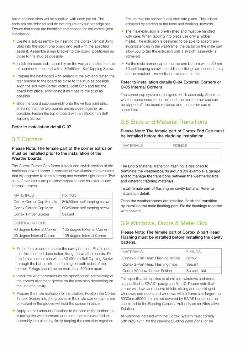
Corners 3.7
Please Note: The female part of the corner extrusion must be installed prior to the installation of the Weatherboards.
The Cortex Corner Cap forms a sleek and stylish version of the traditional boxed corner. It consists of two aluminium extrusions that clip together to form a strong and weather-tight corner. Two sets of extrusions are provided; separate sets for external and internal corners.
MATERIALS FIXINGS
Cortex Corner Cap Female 8Gx50mm self tapping screw
Cortex Corner Cap Male 8Gx50mm self tapping screw
Cortex Timber Scriber Sealant
CONFIGURATIONS
90 degree External Corner 135 degree External Corner
90 degree Internal Corner 135 degree Internal Corner
Fit the female corner cap to the cavity battens. Please note that this must be done before fi xing the weatherboards. Fix the female corner cap with a 8Gx50mm Self Tapping Screw through the batten into the framing on both sides of the corner. Fixings should be no more than 800mm apart.
Install the weatherboards as per specifi cation, terminating at the correct alignment groove on the extrusion depending on the use of a cavity.
Prepare the male extrusion for installation. Position the Cortex Timber Scriber into the grooves in the male corner cap; a line of sealant in the groove will hold the scriber in place.
Apply a small amount of sealant to the face of the scriber that is facing the weatherboard and push the extrusion/scriber assembly into place by fi rmly tapping the extrusion together.
Ensure that the scriber is adjusted into place. This is best achieved by starting at the base and working upwards.
The male extrusion is pre-fi nished and must be handled with care. When tapping into place use only a rubber mallet. The extrusion is designed to be able to absorb any inconsistencies in the wall/frame; the barbs on the male part allow you to tap the extrusion until a straight assembly is achieved.
Fix the male corner cap at the top and bottom with a 50mm 8G self tapping screw, no additional fi xings are needed. (may not be required – no vertical movement so far)
Refer to installation details C-04 External Corners or C-05 Internal Corners
The corner cap system is designed for disassembly. Should a weatherboard need to be replaced, the male corner cap can be clipped off, the board replaced and the corner cap re-assembled.
Ends and Material Transitions3.8
Please Note: The female part of Cortex End Cap must be installed before the cladding installation.
MATERIALS FIXINGS
The End & Material Transition fl ashing is designed to terminate the weatherboards around (for example) a garage and to manage the transitions between the weatherboards and different cladding materials.
Install female part of fl ashing on cavity battens. Refer to installation detail.
Once the weatherboards are installed, fi nish the transition by installing the male fl ashing part. Fix the fl ashings together with sealant.
Windows, Doors & Meter Box3.9
Please Note: The female part of Cortex 2-part Head Flashing must be installed before installing the cavity battens.
MATERIALS FIXINGS
Cortex 2-Part Head Flashing female Screw
Cortex 2-Part Head Flashing male Sealant
Cortex Window Timber Scriber Sealant, Nail
This specifi cation applies to aluminium windows and doors as specifi ed in E2/AS1 paragraph 9.1.10. Please note that timber windows and doors; bi-fold, sliding and non-hinged windows; and doors and windows with a frame size larger than 5000mmx5000mm are not covered by E2/AS1 and must be submitted to the Building Consent Authority as an Alternative Solution.
All windows installed with the Cortex System must comply with NZS 4211 for the relevant Building Wind Zone, or be
specifi cally designed for use in specifi cally designed buildings, have a minimum 10 mm fl ange cover over the cladding, and be installed according to the details in this specifi cation.
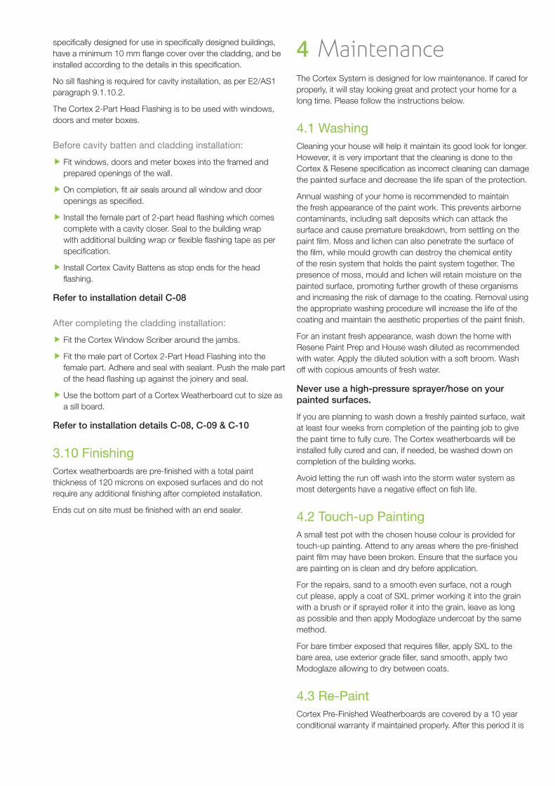
No sill fl ashing is required for cavity installation, as per E2/AS1 paragraph 9.1.10.2.
The Cortex 2-Part Head Flashing is to be used with windows, doors and meter boxes.
Before cavity batten and cladding installation:
Fit windows, doors and meter boxes into the framed and prepared openings of the wall.
On completion, fi t air seals around all window and door openings as specifi ed.
Install the female part of 2-part head fl ashing which comes complete with a cavity closer. Seal to the building wrap with additional building wrap or fl exible fl ashing tape as per specifi cation.
Install Cortex Cavity Battens as stop ends for the head fl ashing.
Refer to installation detail C-08
After completing the cladding installation:
Fit the Cortex Window Scriber around the jambs.
Fit the male part of Cortex 2-Part Head Flashing into the female part. Adhere and seal with sealant. Push the male part of the head fl ashing up against the joinery and seal.
Use the bottom part of a Cortex Weatherboard cut to size as a sill board.
Refer to installation details C-08, C-09 & C-10
Finishing3.10 Cortex weatherboards are pre-fi nished with a total paint thickness of 120 microns on exposed surfaces and do not require any additional fi nishing after completed installation.
Ends cut on site must be fi nished with an end sealer.
Maintenance4 The Cortex System is designed for low maintenance. If cared for properly, it will stay looking great and protect your home for a long time. Please follow the instructions below.
Washing4.1 Cleaning your house will help it maintain its good look for longer. However, it is very important that the cleaning is done to the Cortex & Resene specifi cation as incorrect cleaning can damage the painted surface and decrease the life span of the protection.
Annual washing of your home is recommended to maintain the fresh appearance of the paint work. This prevents airborne contaminants, including salt deposits which can attack the surface and cause premature breakdown, from settling on the paint fi lm. Moss and lichen can also penetrate the surface of the fi lm, while mould growth can destroy the chemical entity of the resin system that holds the paint system together. The presence of moss, mould and lichen will retain moisture on the painted surface, promoting further growth of these organisms and increasing the risk of damage to the coating. Removal using the appropriate washing procedure will increase the life of the coating and maintain the aesthetic properties of the paint fi nish.
For an instant fresh appearance, wash down the home with Resene Paint Prep and House wash diluted as recommended with water. Apply the diluted solution with a soft broom. Wash off with copious amounts of fresh water.
Never use a high-pressure sprayer/hose on your painted surfaces.
If you are planning to wash down a freshly painted surface, wait at least four weeks from completion of the painting job to give the paint time to fully cure. The Cortex weatherboards will be installed fully cured and can, if needed, be washed down on completion of the building works.
Avoid letting the run off wash into the storm water system as most detergents have a negative effect on fi sh life.
Touch-up Painting4.2 A small test pot with the chosen house colour is provided for touch-up painting. Attend to any areas where the pre-fi nished paint fi lm may have been broken. Ensure that the surface you are painting on is clean and dry before application.
For the repairs, sand to a smooth even surface, not a rough cut please, apply a coat of SXL primer working it into the grain with a brush or if sprayed roller it into the grain, leave as long as possible and then apply Modoglaze undercoat by the same method.
For bare timber exposed that requires fi ller, apply SXL to the bare area, use exterior grade fi ller, sand smooth, apply two Modoglaze allowing to dry between coats.
Re-Paint4.3 Cortex Pre-Finished Weatherboards are covered by a 10 year conditional warranty if maintained properly. After this period it is
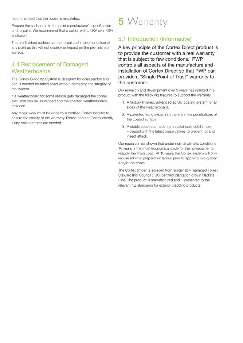
recommended that the house is re-painted.
Prepare the surface as to the paint manufacturer’s specifi cation and re-paint. We recommend that a colour with a LRV over 40% is chosen.
The pre-fi nished surface can be re-painted in another colour at any point as this will not destroy or impact on the pre-fi nished surface.
Replacement of Damaged 4.4 WeatherboardsThe Cortex Cladding System is designed for disassembly and can, if needed be taken apart without damaging the integrity of the system.
If a weatherboard for some reason gets damaged the corner extrusion can be un-clipped and the affected weatherboards replaced.
Any repair work must be done by a certifi ed Cortex Installer to ensure the validity of the warranty. Please contact Cortex directly if any replacements are needed.
Warranty5
Introduction (Informative)5.1 A key principle of the Cortex Direct product is to provide the customer with a real warranty that is subject to few conditions. PWP controls all aspects of the manufacture and installation of Cortex Direct so that PWP can provide a “Single Point of Trust” warranty to the customer.
Our research and development over 3 years has resulted in a product with the following features to support the warranty;
A factory fi nished, advanced acrylic coating system for all 1. sides of the weatherboard.
A patented fi xing system so there are few penetrations of 2. the coated surface.
A stable substrate made from sustainable solid timber 3. – treated with the latest preservatives to prevent rot and insect attack.
Our research has shown that under normal climatic conditions 10 years is the most economical cycle for the homeowner to reapply the fi nish coat. At 10 years the Cortex system will only require minimal preparation labour prior to applying two quality Acrylic top coats.
The Cortex timber is sourced from sustainably managed Forest Stewardship Council (FSC) certifi ed plantation grown Radiata Pine. The product is manufactured and preserved to the relevant NZ standards for exterior cladding products.
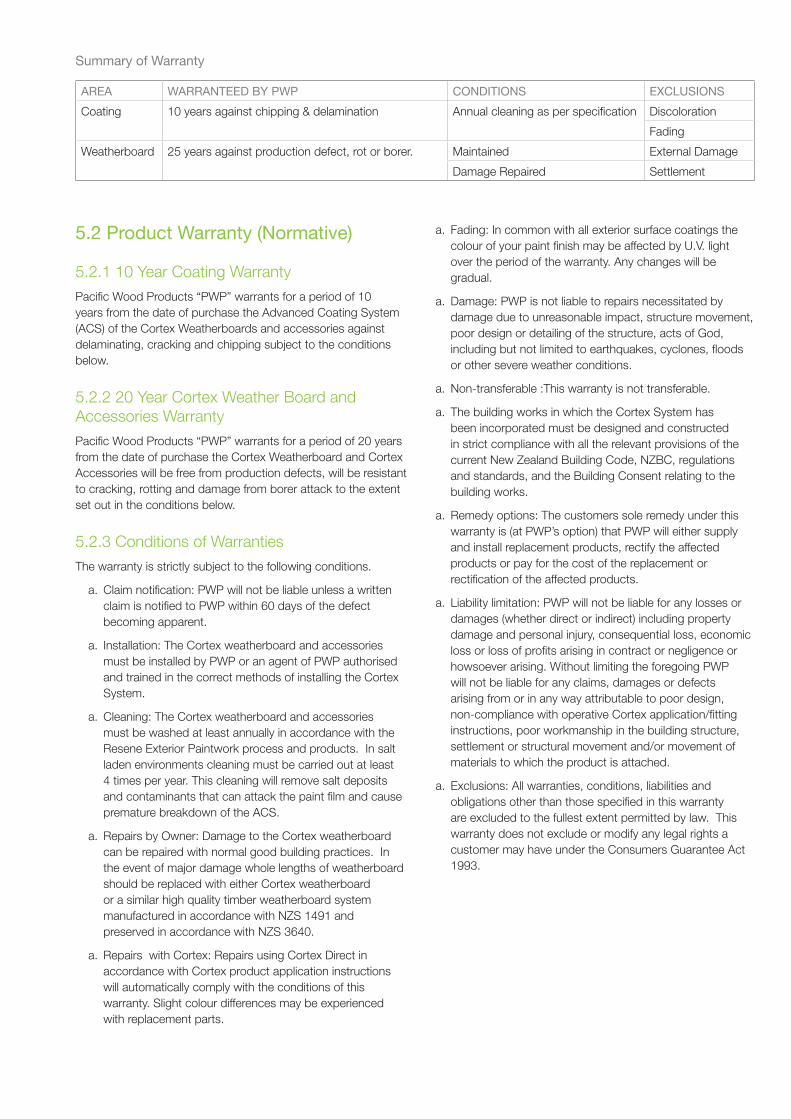
Summary of Warranty
AREA WARRANTEED BY PWP CONDITIONS EXCLUSIONS
Coating 10 years against chipping & delamination Annual cleaning as per specifi cation Discoloration
Fading
Weatherboard 25 years against production defect, rot or borer. Maintained External Damage
Damage Repaired Settlement
Product Warranty (Normative)5.2
10 Year Coating Warranty 5.2.1 Pacifi c Wood Products “PWP” warrants for a period of 10 years from the date of purchase the Advanced Coating System (ACS) of the Cortex Weatherboards and accessories against delaminating, cracking and chipping subject to the conditions below.
20 Year Cortex Weather Board and 5.2.2 Accessories WarrantyPacifi c Wood Products “PWP” warrants for a period of 20 years from the date of purchase the Cortex Weatherboard and Cortex Accessories will be free from production defects, will be resistant to cracking, rotting and damage from borer attack to the extent set out in the conditions below.
Conditions of Warranties5.2.3 The warranty is strictly subject to the following conditions.
Claim notifi cation: PWP will not be liable unless a written a. claim is notifi ed to PWP within 60 days of the defect becoming apparent.
Installation: The Cortex weatherboard and accessories a. must be installed by PWP or an agent of PWP authorised and trained in the correct methods of installing the Cortex System.
Cleaning: The Cortex weatherboard and accessories a. must be washed at least annually in accordance with the Resene Exterior Paintwork process and products. In salt laden environments cleaning must be carried out at least 4 times per year. This cleaning will remove salt deposits and contaminants that can attack the paint fi lm and cause premature breakdown of the ACS.
Repairs by Owner: Damage to the Cortex weatherboard a. can be repaired with normal good building practices. In the event of major damage whole lengths of weatherboard should be replaced with either Cortex weatherboard or a similar high quality timber weatherboard system manufactured in accordance with NZS 1491 and preserved in accordance with NZS 3640.
Repairs with Cortex: Repairs using Cortex Direct in a. accordance with Cortex product application instructions will automatically comply with the conditions of this warranty. Slight colour differences may be experienced with replacement parts.
Fading: In common with all exterior surface coatings the a. colour of your paint fi nish may be affected by U.V. light over the period of the warranty. Any changes will be gradual.
Damage: PWP is not liable to repairs necessitated by a. damage due to unreasonable impact, structure movement, poor design or detailing of the structure, acts of God, including but not limited to earthquakes, cyclones, fl oods or other severe weather conditions.
Non-transferable :This warranty is not transferable.a.
The building works in which the Cortex System has a. been incorporated must be designed and constructed in strict compliance with all the relevant provisions of the current New Zealand Building Code, NZBC, regulations and standards, and the Building Consent relating to the building works.
Remedy options: The customers sole remedy under this a. warranty is (at PWP’s option) that PWP will either supply and install replacement products, rectify the affected products or pay for the cost of the replacement or rectifi cation of the affected products.
Liability limitation: PWP will not be liable for any losses or a. damages (whether direct or indirect) including property damage and personal injury, consequential loss, economic loss or loss of profi ts arising in contract or negligence or howsoever arising. Without limiting the foregoing PWP will not be liable for any claims, damages or defects arising from or in any way attributable to poor design, non-compliance with operative Cortex application/fi tting instructions, poor workmanship in the building structure, settlement or structural movement and/or movement of materials to which the product is attached.
Exclusions: All warranties, conditions, liabilities and a. obligations other than those specifi ed in this warranty are excluded to the fullest extent permitted by law. This warranty does not exclude or modify any legal rights a customer may have under the Consumers Guarantee Act 1993.
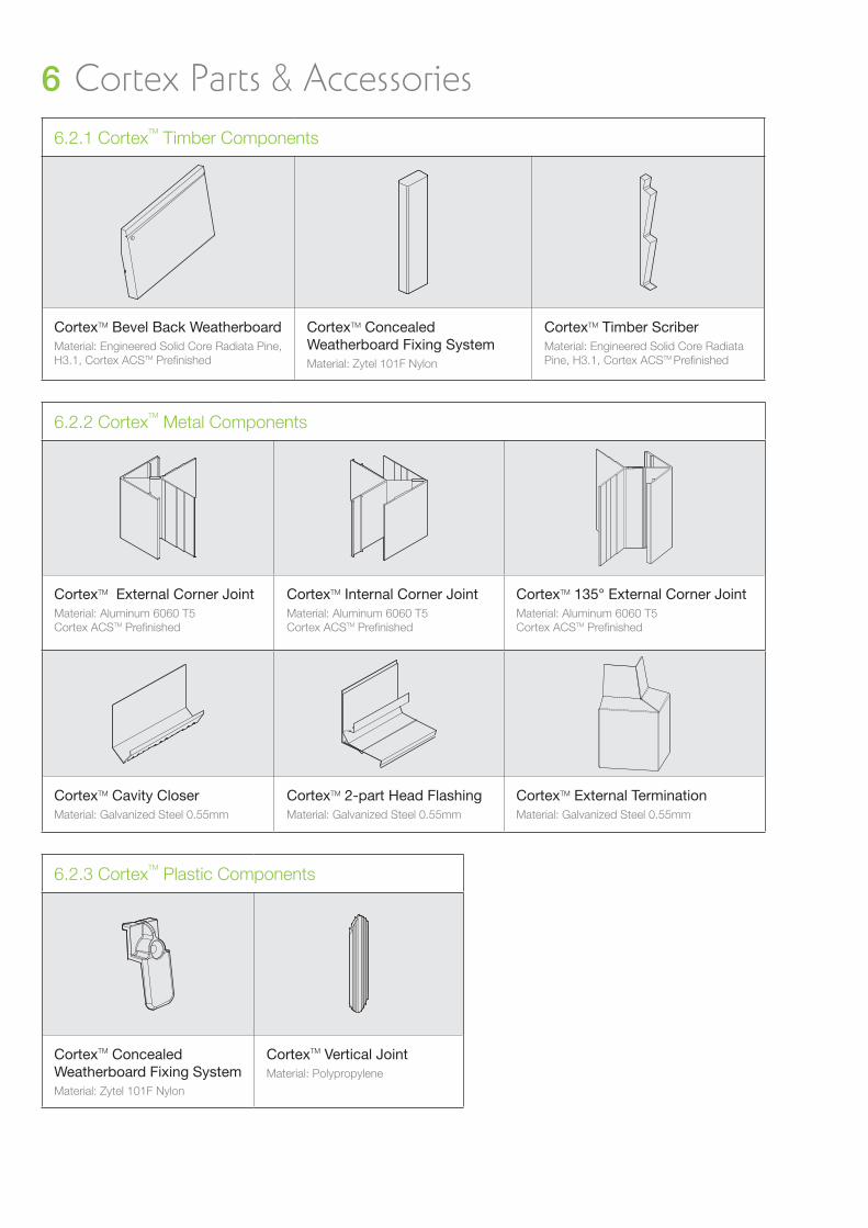
Cortex Parts 6 & AccessoriesCortex6.2.1 TM Timber Components
CortexTM Bevel Back WeatherboardMaterial: Engineered Solid Core Radiata Pine, H3.1, Cortex ACSTM Prefi nished
CortexTM Concealed Weatherboard Fixing SystemMaterial: Zytel 101F Nylon
CortexTM Timber ScriberMaterial: Engineered Solid Core Radiata Pine, H3.1, Cortex ACSTM Prefi nished
Cortex6.2.2 TM Metal Components
CortexTM External Corner JointMaterial: Aluminum 6060 T5Cortex ACSTM Prefi nished
CortexTM Internal Corner JointMaterial: Aluminum 6060 T5Cortex ACSTM Prefi nished
CortexTM 135° External Corner JointMaterial: Aluminum 6060 T5Cortex ACSTM Prefi nished
CortexTM Cavity CloserMaterial: Galvanized Steel 0.55mm
CortexTM 2-part Head FlashingMaterial: Galvanized Steel 0.55mm
CortexTM External TerminationMaterial: Galvanized Steel 0.55mm
Cortex6.2.3 TM Plastic Components
CortexTM Concealed Weatherboard Fixing SystemMaterial: Zytel 101F Nylon
CortexTM Vertical JointMaterial: Polypropylene
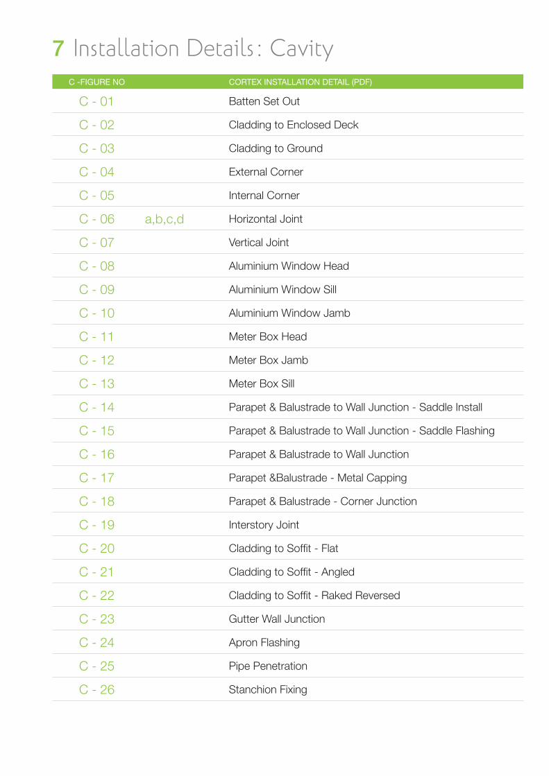
Installation Details: Cavity7 C -FIGURE NO CORTEX INSTALLATION DETAIL (PDF)
C - 01 Batten Set Out
C - 02 Cladding to Enclosed Deck
C - 03 Cladding to Ground
C - 04 External Corner
C - 05 Internal Corner
C - 06 a,b,c,d Horizontal Joint
C - 07 Vertical Joint
C - 08 Aluminium Window Head
C - 09 Aluminium Window Sill
C - 10 Aluminium Window Jamb
C - 11 Meter Box Head
C - 12 Meter Box Jamb
C - 13 Meter Box Sill
C - 14 Parapet & Balustrade to Wall Junction - Saddle Install
C - 15 Parapet & Balustrade to Wall Junction - Saddle Flashing
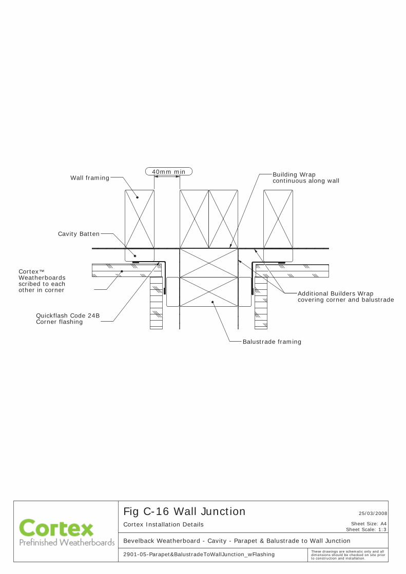
C - 16 Parapet & Balustrade to Wall Junction
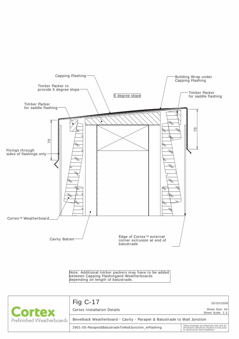
C - 17 Parapet &Balustrade - Metal Capping
C - 18 Parapet & Balustrade - Corner Junction
C - 19 Interstory Joint
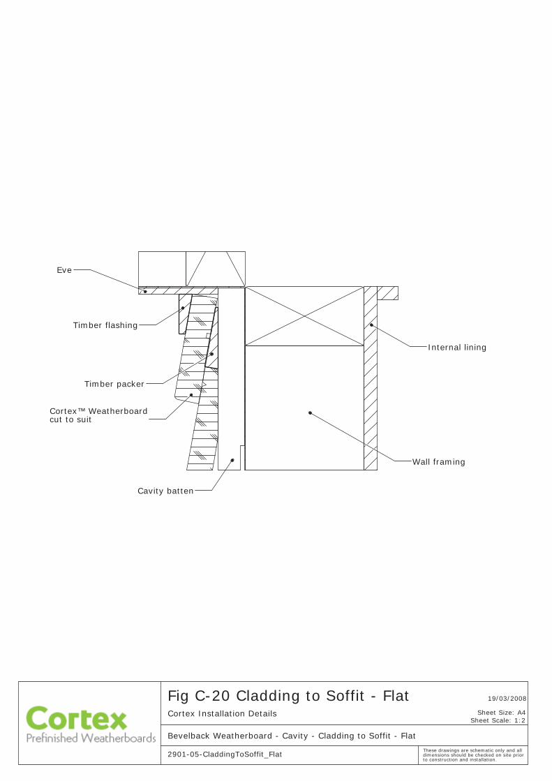
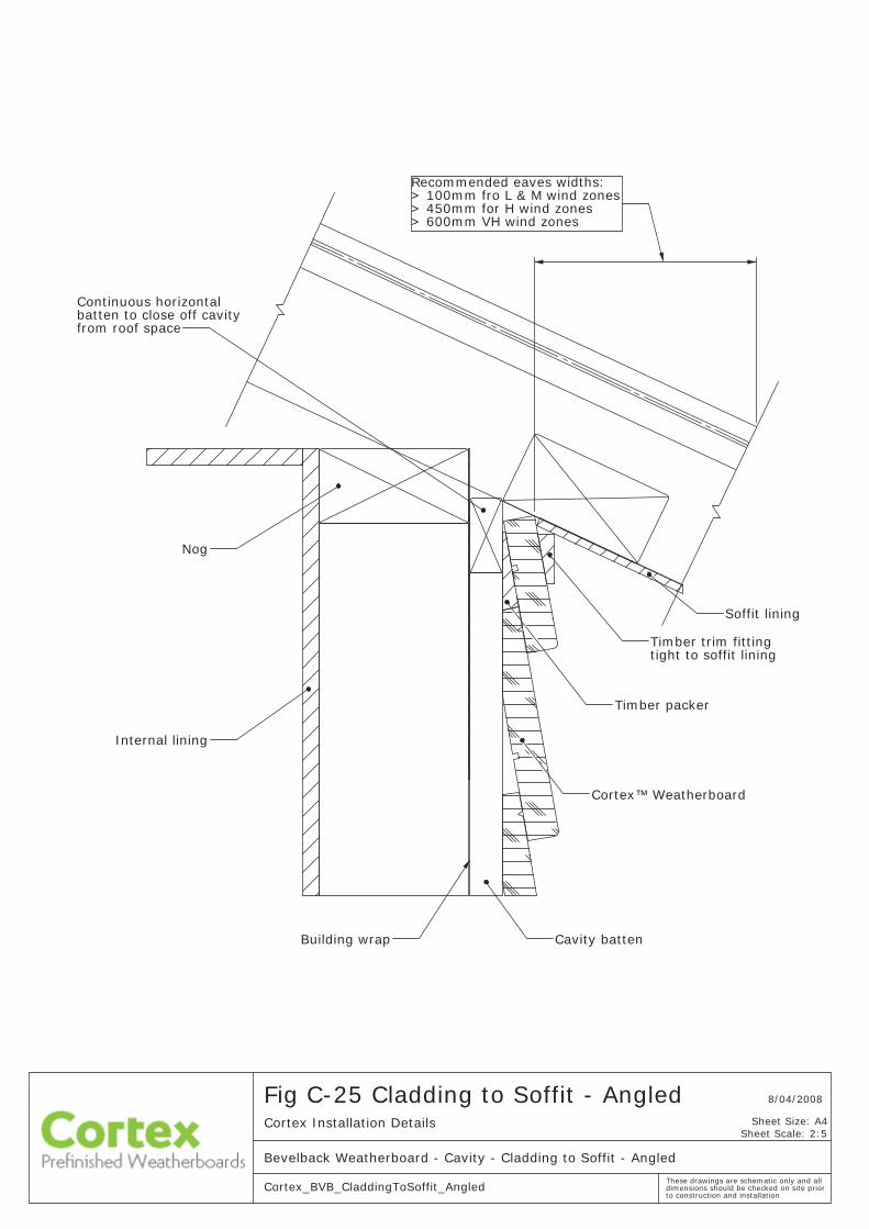
C - 20 Cladding to Soffi t - Flat
C - 21 Cladding to Soffi t - Angled
C - 22 Cladding to Soffi t - Raked Reversed
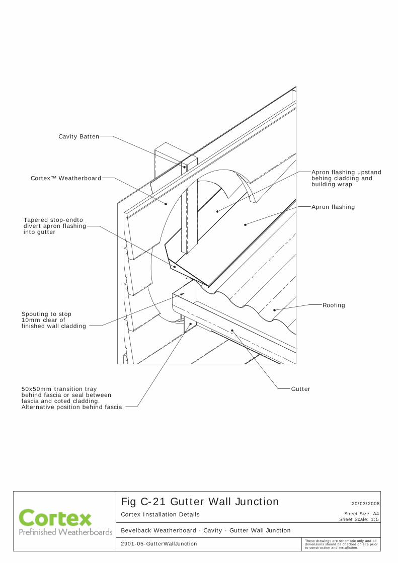
C - 23 Gutter Wall Junction
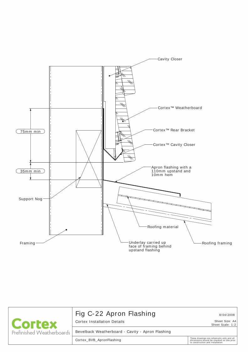
C - 24 Apron Flashing
C - 25 Pipe Penetration
C - 26 Stanchion Fixing
8/04/2008
Sheet Scale: 1:2
to construction and installation.
Fig C-01 Batten Set OutCortex Installation Details
Bevelback Weatherboard - Cavity - Batten Set Out
Cortex_BVB_BattenSetOutThese drawings are schematic only and all dimensions should be checked on site prior
Sheet Size: A4
Cavity Batten
50
NZS3604:1999Stud centre as per
Cavity spacer set to slope at5 degrees min. (1:12)
Building Wrap
according to the ES/AS1 by BRANZ.and acctepted as an Alternative Solution
Weatherboard
Timber Packer
Cavity Batten
™
from deck surface. 150mm min. upstand Decking Membrane,
Cortex
over membrane upstandBuilding wrap lapped
35mm min. clearance
Cavity Closer
DPC
(E2/AS1)from decking highpoint
™Cortex
surface to deck.
100mm step down from internal floor
The Cortex™ Cavity Closer has been tested
Cortex™ Rear Bracket rests on cavity closer and supports the Weatherboardon installation and use
to construction and installation.
Fig C-02 Cladding to Enclosed DeckCortex Installation Details
Bevelback Weatherboard - Cavity - Cladding to Enclosed Deck
Cortex_BVB_CladdingToEnclosedDeck
8/04/2008
Sheet Scale: 1:2
These drawings are schematic only and all dimensions should be checked on site prior
Sheet Size: A4
6mm min.
The Cortex™ Cavity Closer has been tested and acctepted as an Alternative Solution according to the ES/AS1 by BRANZ.
to construction and installation.
Fig C-03 Cladding to GroundCortex Installation Details
Bevelback Weatherboard - Cavity - Cladding To Ground
Cortex_BVB_CladdingToGround
8/04/2008
Sheet Scale: 1:2
These drawings are schematic only and all dimensions should be checked on site prior
Sheet Size: A4
Concrete floor slab
Weatherboard to finish50mm below floor level
DPC
Weatherboard
Building Wrap
Cavity batten
™
Cortex
Cortex
Cavity Closer™
of slab with min 6mmBottom plate to overhang edge
Cortex™ Rear Bracket rests on cavity closer and supports the Weatherboardon installation and use
50mm min
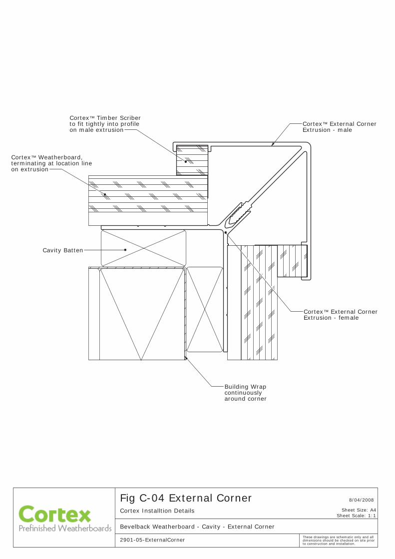
External CornerExtrusion - female
on male extrusion
Cavity Batten
terminating at location line
™
Timber ScriberxetroC eliforp otni ylthgit tif ot ™ External Corner
Cortex
Extrusion - male
on extrusion
™Cortex
Cortex™ Weatherboard,
Building Wrap continuouslyaround corner
Sheet Scale: 1:1
8/04/2008
to construction and installation.
Fig C-04 External CornerCortex Installtion Details
Bevelback Weatherboard - Cavity - External Corner
2901-05-ExternalCornerThese drawings are schematic only and all dimensions should be checked on site prior
Sheet Size: A4
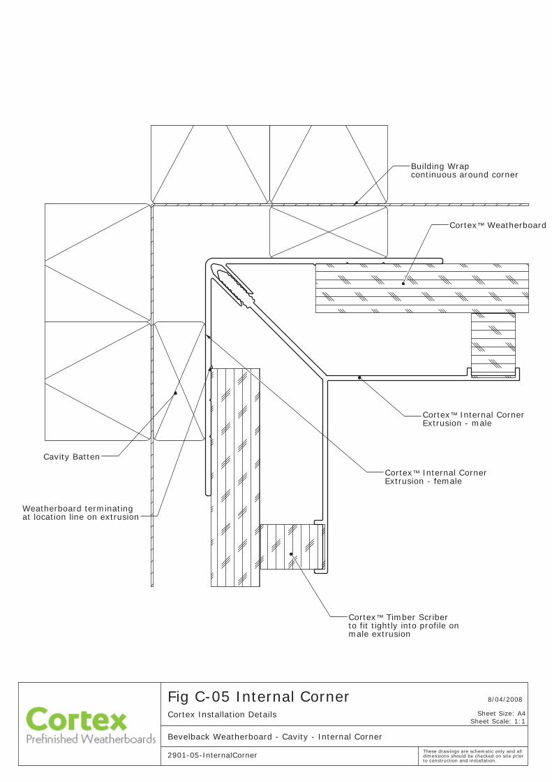
Fig C-05 Internal CornerCortex Installation Details
Bevelback Weatherboard - Cavity - Internal Corner
2901-05-InternalCorner
8/04/2008
Sheet Scale: 1:1
These drawings are schematic only and all dimensions should be checked on site prior to construction and installation.
Sheet Size: A4
Building Wrapcontinuous around corner
Cavity Batten
Cortex™ Internal CornerExtrusion - female
Cortex™ Internal Corner Extrusion - male
Cortex™ Timber Scriberto fit tightly into profile onmale extrusion
Cortex™ Weatherboard
Weatherboard terminatingat location line on extrusion
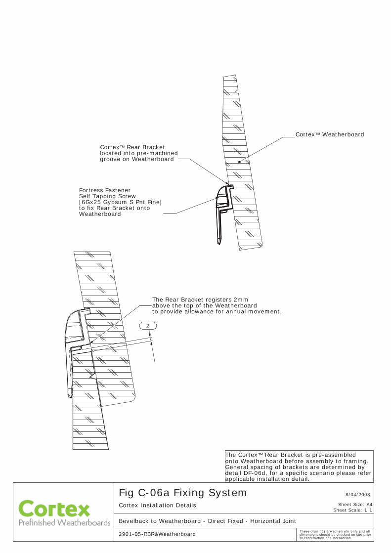
Cortex™ Weatherboard
Cortex™ Rear Bracketlocated into pre-machined groove on Weatherboard
Fortress Fastener Self Tapping Screw[6Gx25 Gypsum S Pnt Fine]to fix Rear Bracket onto Weatherboard
Fig C-06a Fixing SystemCortex Installation Details
Bevelback to Weatherboard - Direct Fixed - Horizontal Joint
2901-05-RBR&Weatherboard
8/04/2008
Sheet Scale: 1:1
These drawings are schematic only and all dimensions should be checked on site prior to construction and installation.
Sheet Size: A4
The Cortex™ Rear Bracket is pre-assembledonto Weatherboard before assembly to framing. General spacing of brackets are determined by detail DF-06d, for a specific scenario please refer applicable installation detail.
The Rear Bracket registers 2mmabove the top of the Weatherboardto provide allowance for annual movement.
2
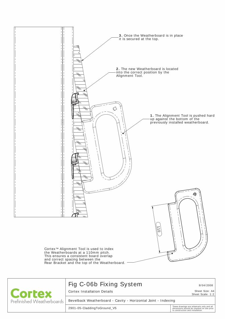
Cortex™ Alignment Tool is used to index the Weatherboards at a 110mm pitch. This ensures a consistent board overlap and correct spacing between the Rear Bracket and the top of the Weatherboard.
110
Fig C-06b Fixing SystemCortex Installation Details
Bevelback Weatherboard - Cavity - Horizontal Joint - Indexing
2901-05-CladdingToGround_V5
8/04/2008
Sheet Scale: 1:2
These drawings are schematic only and all dimensions should be checked on site prior to construction and installation.
Sheet Size: A4
2. The new Weatherboard is located into the correct position by the Alignment Tool.
1. The Alignment Tool is pushed hard up against the bottom of the previously installed weatherboard.
3. Once the Weatherboard is in place it is secured at the top.
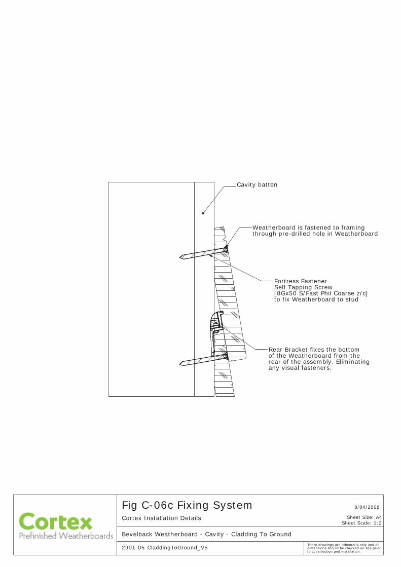
Fig C-06c Fixing SystemCortex Installation Details
Bevelback Weatherboard - Cavity - Cladding To Ground
2901-05-CladdingToGround_V5
8/04/2008
Sheet Scale: 1:2
These drawings are schematic only and all dimensions should be checked on site prior to construction and installation.
Sheet Size: A4
Fortress Fastener Self Tapping Screw[8Gx50 S/Fast Phil Coarse z/c]to fix Weatherboard to stud
Weatherboard is fastened to framingthrough pre-drilled hole in Weatherboard
Cavity batten
Rear Bracket fixes the bottomof the Weatherboard from therear of the assembly. Eliminatingany visual fasteners.
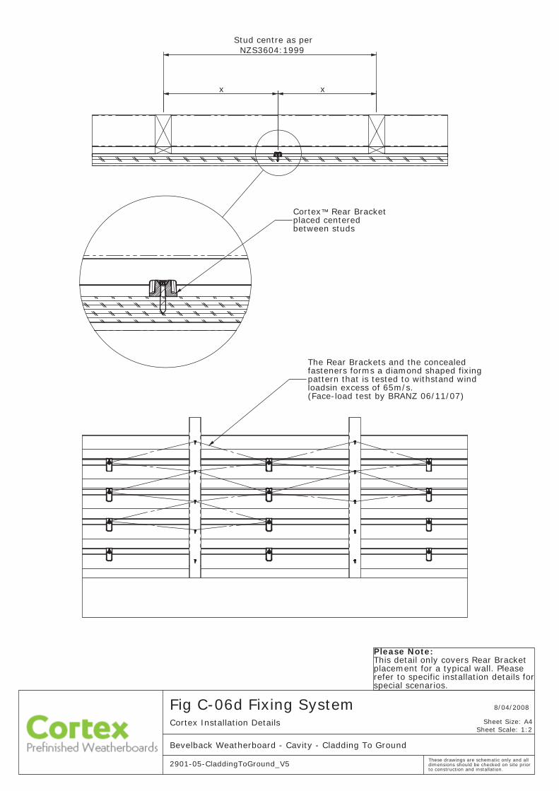
x
Stud centre as perNZS3604:1999
x
The Rear Brackets and the concealed fasteners forms a diamond shaped fixing pattern that is tested to withstand wind loadsin excess of 65m/s. (Face-load test by BRANZ 06/11/07)
Please Note:This detail only covers Rear Bracket placement for a typical wall. Please refer to specific installation details forspecial scenarios.
Fig C-06d Fixing SystemCortex Installation Details
Bevelback Weatherboard - Cavity - Cladding To Ground
2901-05-CladdingToGround_V5
8/04/2008
Sheet Scale: 1:2
These drawings are schematic only and all dimensions should be checked on site prior to construction and installation.
Sheet Size: A4
Cortex™ Rear Bracketplaced centered between studs
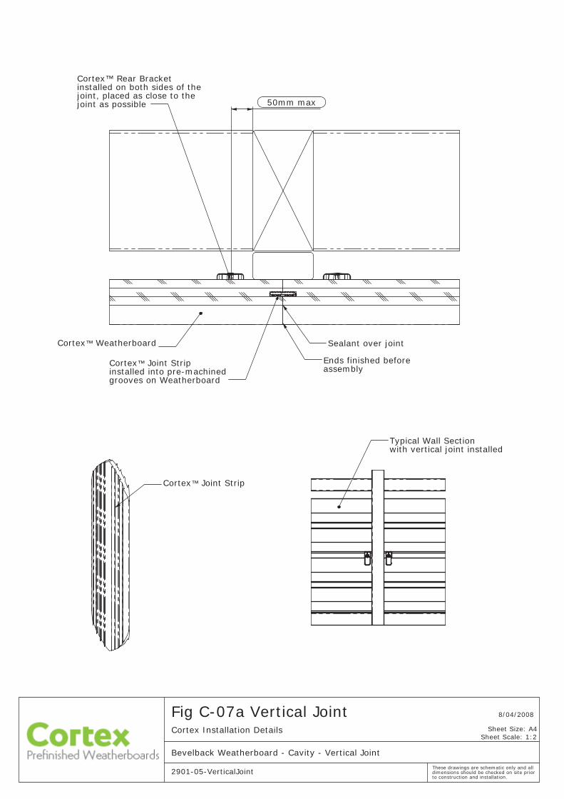
Cortex™ Weatherboard
Cortex™ Joint Stripinstalled into pre-machined grooves on Weatherboard
Sealant over joint
Cortex™ Rear Bracket installed on both sides of the joint, placed as close to the joint as possible
Ends finished before assembly
50mm max
Cortex™ Joint Strip
Typical Wall Sectionwith vertical joint installed
Fig C-07a Vertical JointCortex Installation Details
Bevelback Weatherboard - Cavity - Vertical Joint
2901-05-VerticalJoint
8/04/2008
Sheet Scale: 1:2
These drawings are schematic only and all dimensions should be checked on site prior to construction and installation.
Sheet Size: A4
mm
86
R19 typ
Fig C-07b Vertical JointCortex Installation Details
Bevelback Weatherboard - Cavity - Vertical Joint
2901-05-VerticalJoint
8/04/2008
Sheet Scale: 1:2
These drawings are schematic only and all dimensions should be checked on site prior to construction and installation.
Sheet Size: A4
Board ends must be painted aftermachining ad before assebly. Sealant is then used to seal the assembled joint.
3mm
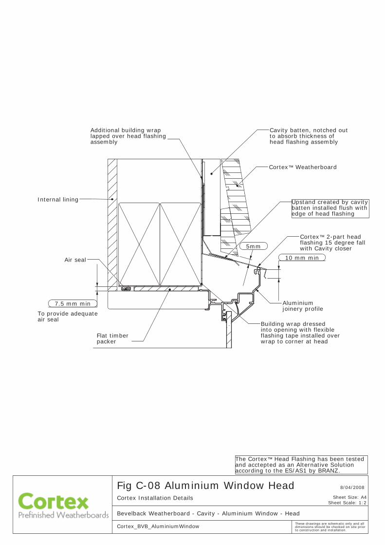
The Cortex™ Head Flashing has been tested and acctepted as an Alternative Solution according to the ES/AS1 by BRANZ.
Sheet Scale: 1:2
Bevelback Weatherboard - Cavity - Aluminium Window - Head
to construction and installation. Cortex_BVB_AluminiumWindow
Cortex Installation Details
8/04/2008Fig C-08 Aluminium Window Head
These drawings are schematic only and all dimensions should be checked on site prior
Sheet Size: A4
flashing tape installed over Flat timber wrap to corner at head
assemblylapped over head flashing Additional building wrap
into opening with flexible
Internal lining
air sealTo provide adequate
Air seal
Cortex™ Weatherboard
packer
Building wrap dressed
Cavity batten, notched out
with Cavity closer
to absorb thickness of
flashing 15 degree fall 2-part head
Aluminium
head flashing assembly
joinery profile
Cortex™
Upstand created by cavity batten installed flush withedge of head flashing
7.5 mm min
10 mm min
5mm
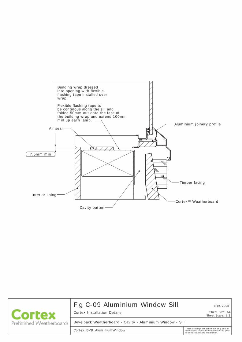
Fig C-09 Aluminium Window SillCortex Installation Details
Bevelback Weatherboard - Cavity - Aluminium Window - Sill
Cortex_BVB_AluminiumWindow
8/04/2008
Sheet Scale: 1:2
These drawings are schematic only and all dimensions should be checked on site prior to construction and installation.
Sheet Size: A4
Building wrap dressedinto opening with flexibleflashing tape installed over wrap.
Flexible flashing tape to be continous along the sill andfolded 50mm out onto the face of the building wrap and extend 100mmmid up each jamb.
Cortex™ Weatherboard
Cavity batten
Interior lining
Aluminium joinery profileAir seal
Timber facing
7.5mm min
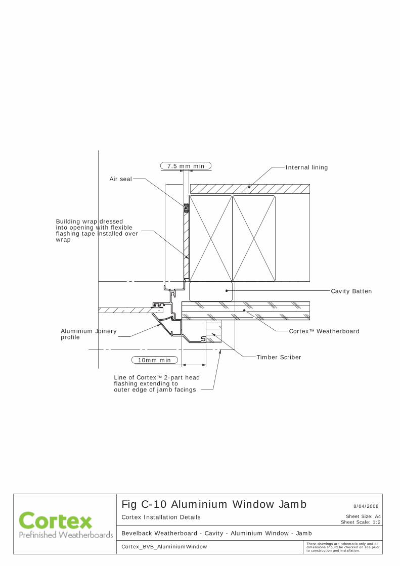
Fig C-10 Aluminium Window JambCortex Installation Details
Bevelback Weatherboard - Cavity - Aluminium Window - Jamb
Cortex_BVB_AluminiumWindow
8/04/2008
Sheet Scale: 1:2
These drawings are schematic only and all dimensions should be checked on site prior to construction and installation.
Sheet Size: A4
Cortex™ Weatherboard
Timber Scriber
Cavity Batten
Building wrap dressed into opening with flexibleflashing tape installed over wrap
Aluminium Joineryprofile
Line of Cortex™ 2-part headflashing extending to outer edge of jamb facings
Internal lining
Air seal
7.5 mm min
10mm min
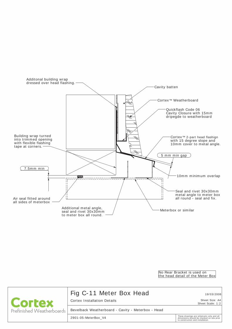
Cavity Closure with 15mm
the head detail of the Meter Box
Weatherboard™Cortex
10mm cover to metal angle. with 15 degree slope and
™ 2-part head flashign
Meterbox or similar
all sides of meterbox
Cavity batten
Air seal fitted around
Cortex
tape at corners.with flexible flashing
dressed over head flashing.Additonal building wrap
into trimmed opening
all round - seal and fix. metal angle to meter box Seal and rivet 30x30mm
dripegde to weatherboard
Quickflash Code 06
Building wrap turned
10mm minimum overlap
No Rear Bracket is used on
Additional metal angle, seal and rivet 30x30mmto meter box all round.
7.5mm min
5 mm min gap
to construction and installation.
Fig C-11 Meter Box HeadCortex Installation Details
Bevelback Weatherboard - Cavity - Meterbox - Head
2901-05-MeterBox_V4
19/03/2008
Sheet Scale: 1:2
These drawings are schematic only and all dimensions should be checked on site prior
Sheet Size: A4
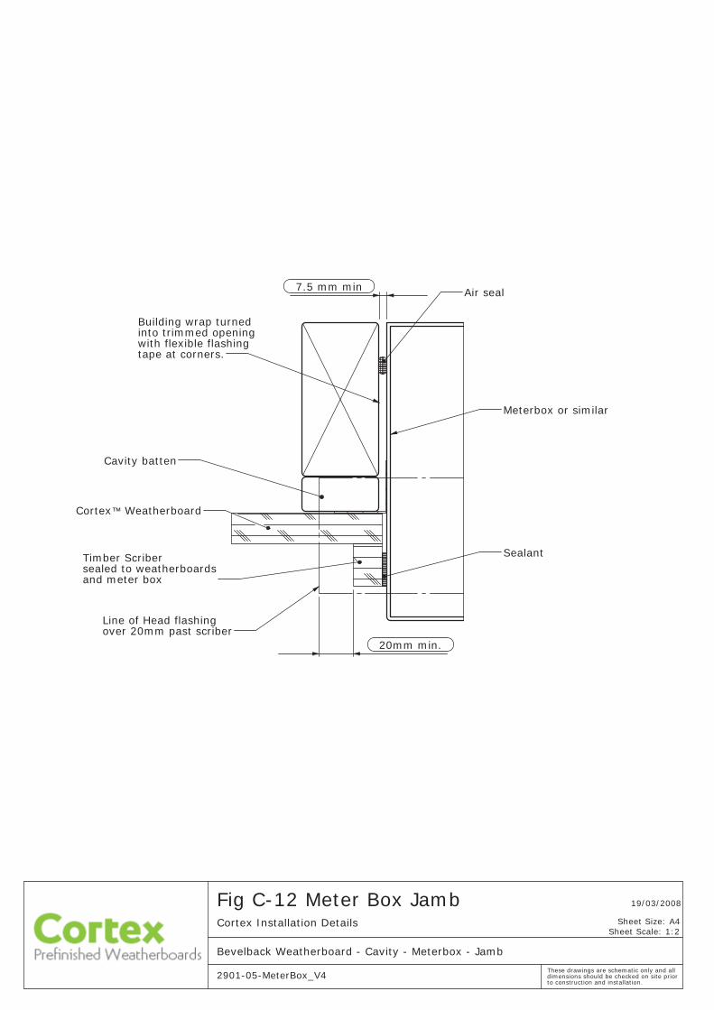
20mm min.
2901-05-MeterBox_V4
Cortex Installation Details
Bevelback Weatherboard - Cavity - Meterbox - Jamb
19/03/2008Fig C-12 Meter Box Jamb
to construction and installation.
Sheet Scale: 1:2
These drawings are schematic only and all dimensions should be checked on site prior
Sheet Size: A4
Line of Head flashingover 20mm past scriber
Air seal
Weatherboard
Cavity batten
™Cortex
Meterbox or similar
and meter boxsealed to weatherboardsTimber Scriber
tape at corners.with flexible flashing
Building wrap turned into trimmed opening
Sealant
7.5 mm min
to construction and installation.
Fig C-13 Meter Box SillCortex Installation Details
Bevelback Weatherboard - Cavity - Meterbox - Sill
2901-05-MeterBox_V4
19/03/2008
Sheet Scale: 1:2
These drawings are schematic only and all dimensions should be checked on site prior
Sheet Size: A4
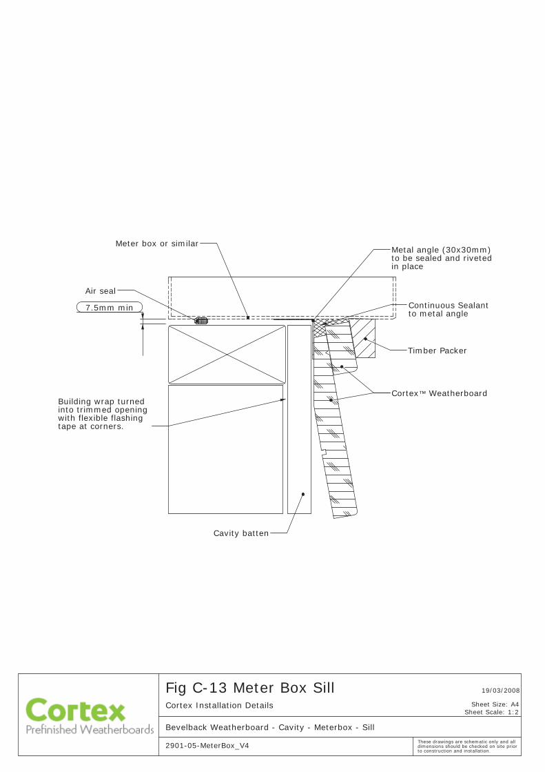
Meter box or similar
Air seal
with flexible flashing tape at corners.
in place
into trimmed opening
Timber Packer
Building wrap turned
Cavity batten
Cortex™ Weatherboard
Metal angle (30x30mm)to be sealed and riveted
Continuous Sealantto metal angle
7.5mm min
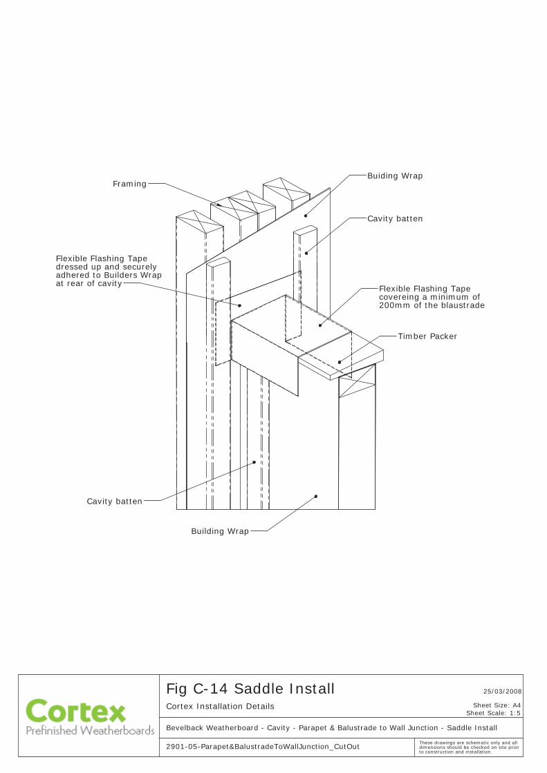
Cavity batten
Building Wrap
FramingBuiding Wrap
Cavity batten
at rear of cavityadhered to Builders Wrapdressed up and securely
200mm of the blaustrade
Flexible Flashing Tape
Flexible Flashing Tapecovereing a minimum of
Timber Packer
Sheet Scale: 1:5Cortex Installation Details
to construction and installation.
25/03/2008
2901-05-Parapet&BalustradeToWallJunction_CutOut
Fig C-14 Saddle Install
Bevelback Weatherboard - Cavity - Parapet & Balustrade to Wall Junction - Saddle Install
These drawings are schematic only and all dimensions should be checked on site prior
Sheet Size: A4
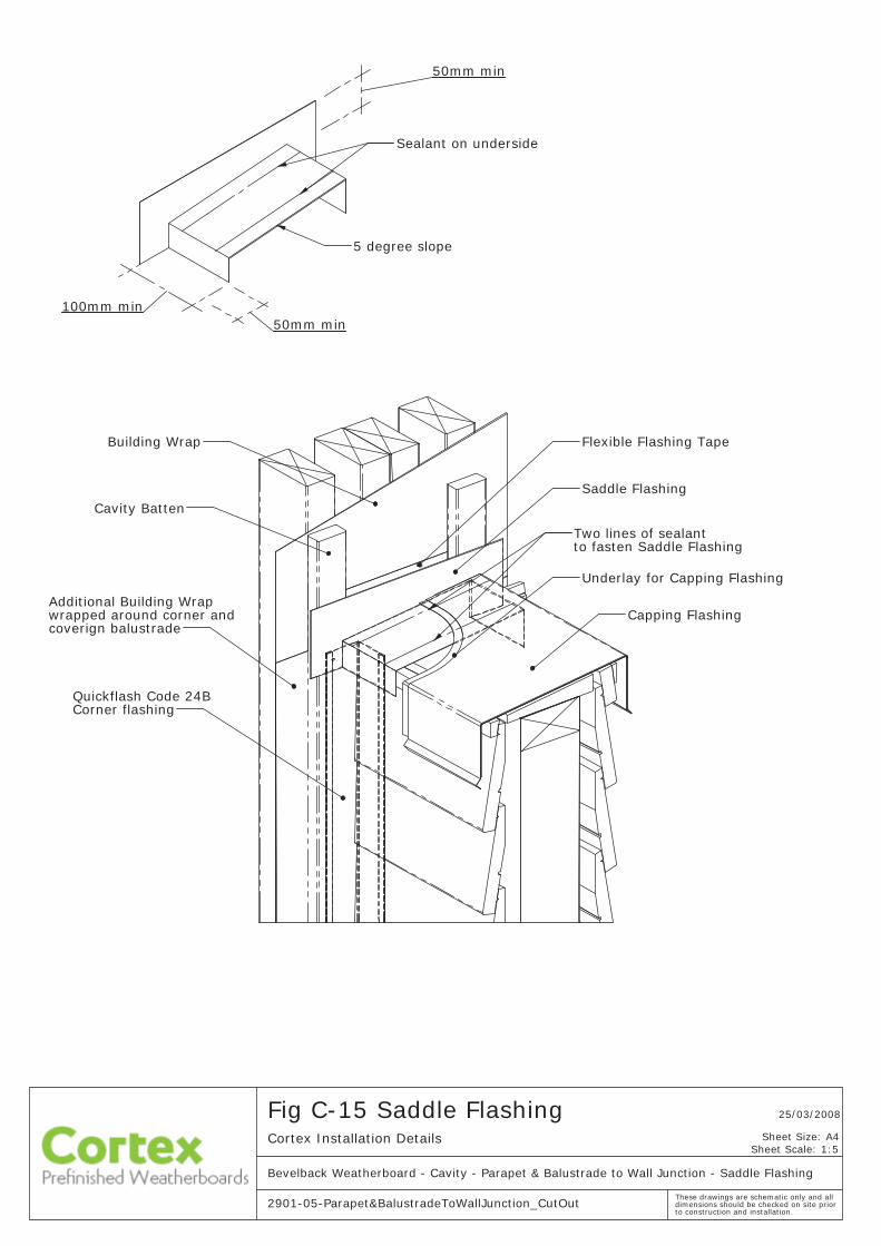
50mm min
5 degree slope
100mm min50mm min
Sealant on underside
to construction and installation.
Fig C-15 Saddle FlashingCortex Installation Details
Bevelback Weatherboard - Cavity - Parapet & Balustrade to Wall Junction - Saddle Flashing
2901-05-Parapet&BalustradeToWallJunction_CutOut
25/03/2008
Sheet Scale: 1:5
These drawings are schematic only and all dimensions should be checked on site prior
Sheet Size: A4
Flexible Flashing TapeBuilding Wrap
Saddle Flashing
coverign balustradewrapped around corner and
Corner flashingQuickflash Code 24B
Additional Building Wrap
Underlay for Capping Flashing
Cavity Batten
Two lines of sealant to fasten Saddle Flashing
Capping Flashing
to construction and installation.
Fig C-16 Wall JunctionCortex Installation Details
Bevelback Weatherboard - Cavity - Parapet & Balustrade to Wall Junction
2901-05-Parapet&BalustradeToWallJunction_wFlashing
25/03/2008
Sheet Scale: 1:3
These drawings are schematic only and all dimensions should be checked on site prior
Sheet Size: A4
Cavity Batten
Wall framing
Balustrade framing
Weatherboardsscribed to each
Building Wrapcontinuous along wall
other in corner
Corner flashingQuickflash Code 24B
Cortex™
Additional Builders Wrapcovering corner and balustrade
40mm min
to construction and installation.
Fig C-17Cortex Installation Details
Bevelback Weatherboard - Cavity - Parapet & Balustrade to Wall Junction
2901-05-Parapet&BalustradeToWallJunction_wFlashing
25/03/2008
Sheet Scale: 1:2
These drawings are schematic only and all dimensions should be checked on site prior
Sheet Size: A4
5 degree slope
depending on length of balustrade.
Capping FlashingCapping FlashingBuilding Wrap under
provide 5 degree slopeTimber Packer to
sides of flashings only
balustrade
Timber Packerfor saddle flashing
Cavity Batten corner extrusion at end of external
Weatherboard™
Fixings through
Cortex
™Edge of Cortex
Note: Additional timber packers may have to be added between Capping Flashingand Weatherboards
Timber Packerfor saddle flashing
70
70
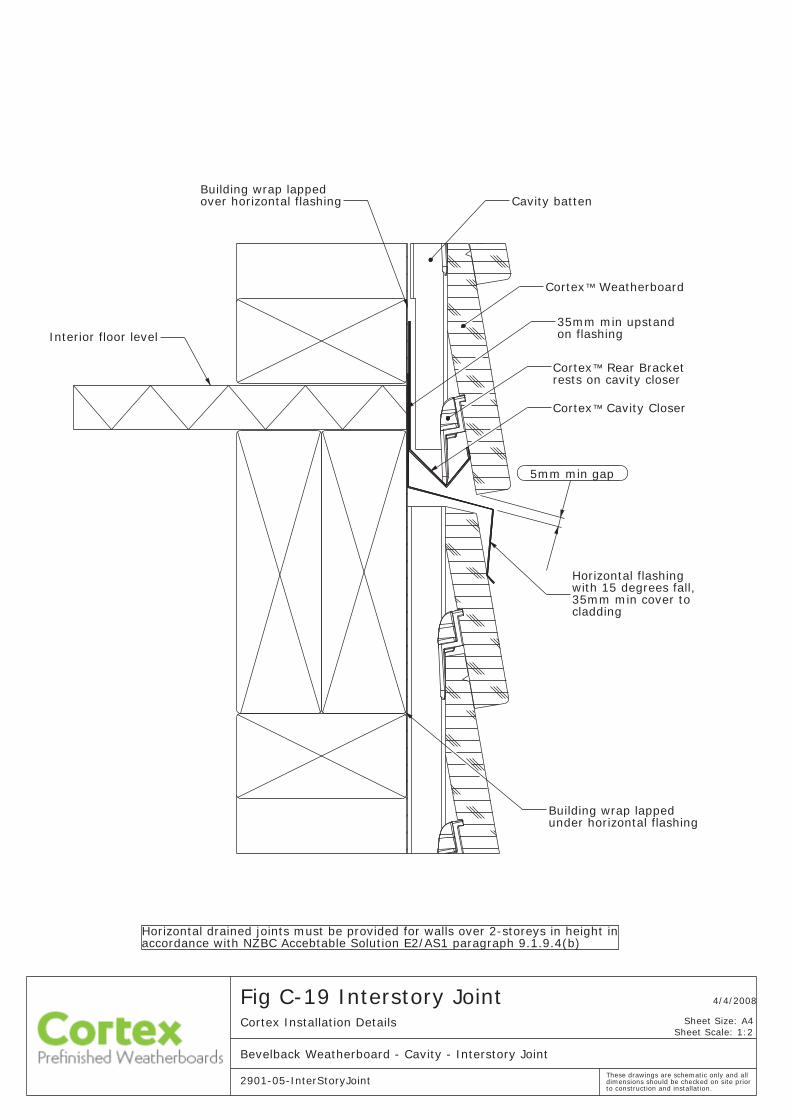
Fig C-19 Interstory Joint 4/4/2008
to construction and installation.
Sheet Scale: 1:2Cortex Installation Details
2901-05-InterStoryJoint
Bevelback Weatherboard - Cavity - Interstory Joint
These drawings are schematic only and all dimensions should be checked on site prior
Sheet Size: A4
Cavity batten
with 15 degrees fall,
Interior floor level
35mm min cover to
Cortex Cavity Closer
Horizontal flashing
™ Weatherboard
cladding
™
Cortex
Horizontal drained joints must be provided for walls over 2-storeys in height inaccordance with NZBC Accebtable Solution E2/AS1 paragraph 9.1.9.4(b)
5mm min gap
Building wrap lappedover horizontal flashing
Cortex™ Rear Bracket rests on cavity closer
35mm min upstand on flashing
Building wrap lappedunder horizontal flashing
Sheet Scale: 1:2
Bevelback Weatherboard - Cavity - Cladding to Soffit - Flat
Cortex Installation Details
to construction and installation. 2901-05-CladdingToSoffit_Flat
19/03/2008Fig C-20 Cladding to Soffit - Flat
These drawings are schematic only and all dimensions should be checked on site prior
Sheet Size: A4
Timber packer
Cavity batten
Internal lining
Timber flashing
cut to suit
Wall framing
Cortex™ Weatherboard
Eve
Sheet Scale: 1:5
20/03/2008
to construction and installation.
Bevelback Weatherboard - Cavity - Gutter Wall Junction
Fig C-21 Gutter Wall JunctionCortex Installation Details
2901-05-GutterWallJunctionThese drawings are schematic only and all dimensions should be checked on site prior
Sheet Size: A4
Spouting to stop10mm clear offinished wall cladding
Cortex™ Weatherboard
Alternative position behind fascia.
Gutter
Roofing
fascia and coted cladding. behind fascia or seal between
building wrap
Apron flashing
behing cladding and Apron flashing upstand
into gutter
50x50mm transition tray
Tapered stop-endtodivert apron flashing
Cavity Batten
8/04/2008
Cortex_BVB_ApronFlashingto construction and installation.
Fig C-22 Apron FlashingCortex Installation Details
Bevelback Weatherboard - Cavity - Apron Flashing
Sheet Scale: 1:2
These drawings are schematic only and all dimensions should be checked on site prior
Sheet Size: A4
Cortex™ Rear Bracket
Cortex™ Cavity Closer
Roofing material
Cortex™ Weatherboard
Roofing framingface of framing behindupstand flashing
Cavity Closer
Support Nog
Framing Underlay carried up
Apron flashing with a 110mm upstand and 10mm hem
35mm min
75mm min
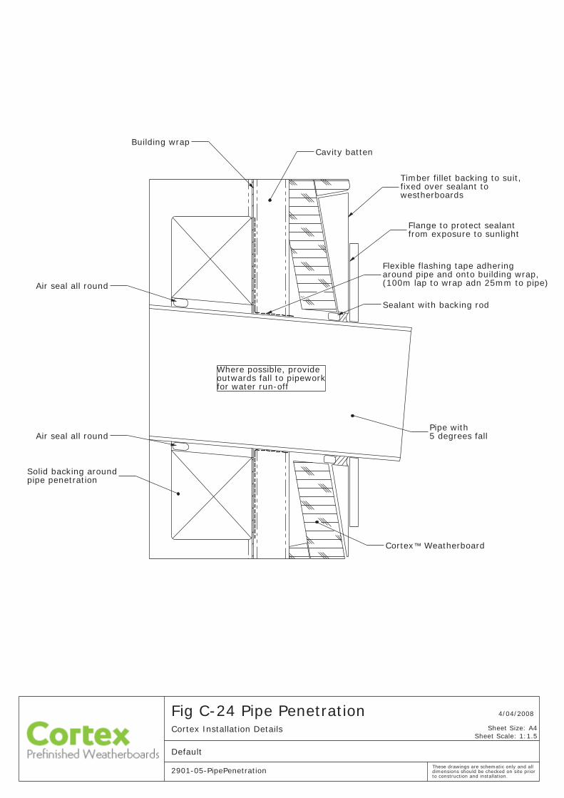
outwards fall to pipeworkfor water run-off
Air seal all round
pipe penetrationSolid backing around
5 degrees fall
Sealant with backing rod
from exposure to sunlightFlange to protect sealant
Pipe with
fixed over sealant to westherboards
around pipe and onto building wrap, Flexible flashing tape adhering
Air seal all round
(100m lap to wrap adn 25mm to pipe)
Cavity batten
Timber fillet backing to suit,
Building wrap
Where possible, provide
Cortex™ Weatherboard
4/04/2008
to construction and installation. 2901-05-PipePenetration
Fig C-24 Pipe PenetrationCortex Installation Details
Default
Sheet Scale: 1:1.5
These drawings are schematic only and all dimensions should be checked on site prior
Sheet Size: A4
Cortex Installation Details
Cortex_BVB_CladdingToSoffit_Angled
Bevelback Weatherboard - Cavity - Cladding to Soffit - Angled
Fig C-25 Cladding to Soffit - Angled 8/04/2008
to construction and installation.
Sheet Scale: 2:5
These drawings are schematic only and all dimensions should be checked on site prior
Sheet Size: A4
Internal lining
Cortex™ Weatherboard
Nog
from roof spacebatten to close off cavityContinuous horizontal
Soffit lining
tight to soffit lining
Timber packer
Recommended eaves widths:> 100mm fro L & M wind zones> 450mm for H wind zones> 600mm VH wind zones
Timber trim fitting
Cavity battenBuilding wrap
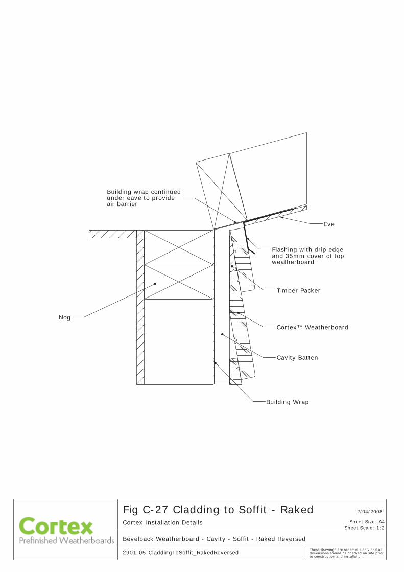
Fig C-27 Cladding to Soffit - Raked
2901-05-CladdingToSoffit_RakedReversed
Sheet Scale: 1:2
2/04/2008
Bevelback Weatherboard - Cavity - Soffit - Raked Reversed
to construction and installation.
Cortex Installation Details
These drawings are schematic only and all dimensions should be checked on site prior
Sheet Size: A4
Cavity Batten
Nog
Building Wrap
under eave to provide air barrier
Eve
Building wrap continued
Cortex™ Weatherboard
Timber Packer
Flashing with drip edge and 35mm cover of topweatherboard


Contact Cortex0800 CORTEX
(06) 834 34 35
www.cortex.co.nz
Prefinished Weatherboards
CortexTM
![Shop Notas de implementação [Exercício da Disciplina de ADAV] http://www.dei.isep.ipp.pt/~jtavares/ADAV/downloads/ADAV_Proj_Rreferencia.pdf http://www.dei.isep.ipp.pt/~jtavares/ADAV/downloads/ADAV_Proj_Rreferencia.pdf](https://img.pdfslide.net/doc/110x75/552fc0fc497959413d8ba1d0/shop-notas-de-implementacao-exercicio-da-disciplina-de-adav-httpwwwdeiisepippptjtavaresadavdownloadsadavprojrreferenciapdf-httpwwwdeiisepippptjtavaresadavdownloadsadavprojrreferenciapdf.jpg)