Embed Size (px)
Citation preview

Weight:Complete solenoid: 6 gArmature: 1.6 g
Standard:Voltage: 24 V DCFlying leads: 5 cm
Thermal stability: E (max. permissibletemperature = 120 °C)
Insulationaccording toDIN VDE 0110 -1: 0.5 KV/1Test voltage: 500 V (eff)
Long life expectancy due to armature bearing in plastic bobbin.
Force vs. Stroke diagramm F = f (s)
Force measured when operating in horizontal position, at 90 % rated voltage and with winding atoperating temperature
stroke s = 0 corresponds to armature infully home position
Gewicht:Magnet: 6 g
Anker: 1,6 gStandard:
Spannung: 24 V DCLitze: 5 cm
Thermische Klasse: E (Tgrenz = 120 °C)
Isolation nachDIN VDE 0110 -1: 0,5 KV/1Prüfspannung: 500 V (eff)
Hohe Lebensdauer durch Ankerlagerungim Kunststoffspulenkörper.
Kraft-Weg-Diagramm F = f (s)
Kraft bei waagerechter Bewegungsrichtung undbei 90 % Nennspannung und betriebswarmerWicklung
Hub s = 0 entspricht dem angezogenen,bestromten Zustand
HubmagnetH 08
Stoßende Ausführung
Linear SolenoidH 08
Thrust type
KUHNKE Magnetkatalog 09/08 66 KUHNKE Solenoid Catalogue 09/08
Bestellformel H 08 – F – 24 V DC 100 % ED Order specifications
HubmagnetGröße
H08
Linear solenoidSizes
Anschlussart
Nennspannung (Standardspannung)1)
Zulässige relative Einschaltdauer bei Luftkühlung
Litze (Standardlänge 5 cm) F24
100 % ED
Coil terminalsFlying leads (5 cm standard length)
Nominal voltage (standard voltage)1)
Perm. duty cycle under air cooled conditions (LK)
H08 - F
24 V DC 100%ED
1) Die Magnete sind bis 24 V DC lieferbar 1) Other voltages are available up to 24 V DC
Zul. rel. Einschaltdauer (ED)2) % 100 50 30 15 5 % Perm. duty cycle (ED)2)
Nennaufnahme Pn W 1,1 2,3 3,6 6,9 18 W Nominal coil power Pn
0 0,5 1,0 1,5 2,0s/mm
F/N
0,01
0,1
1
10 %ED
30
15
5
50
100
2) Bei Montage auf eine Kühlfläche von mindestens 45 cm2 ist die 1,3fache ED zulässig
2) If solenoid is mounted directly onto a flat metal surface of at least 45 cm2, the duty cycle can be extended up to 1.3 x nominal rating

HubmagnetH 08
Stoßende Ausführung
Linear SolenoidH 08
Thrust type
KUHNKE Magnetkatalog 09/08 67 KUHNKE Solenoid Catalogue 09/08
1,5
50 + 15
4
10
3 3 8
3,3 7
21
5 ± 0,2
M2
Hub 2 ± 0,3
15,5
Maße im bestromten Zustand
<–––––––Hubrichtung
Dimensions given with armature in fully home position<–––––––Direction of stroke
Stoßmagnet H 08 Series H 08 thrust type solenoid

Weight:Complete solenoid: 6.3 gArmature: 2 g
Standard:Voltage: 24 V DCFlying leads: 5 cm
Thermal stability: E (max. permissibletemperature = 120 °C)
Insulationaccording toDIN VDE 0110 -1: 0.5 KV/1Test voltage: 500 V (eff)
Long life expectancy due to armaturebearing in plastic bobbin.Return spring F (0 mm) = 0.1 N and F (2 mm) = 0.03 N.
Force vs. Stroke diagramm F = f (s)
Force measured when operating in horizontal position, at 90 % rated voltage and with winding at operating temperature
stroke s = 0 corresponds to armature infully home position
Gewicht:Magnet: 6,3 g
Anker: 2 gStandard:
Spannung: 24 V DCLitze: 5 cm
ThermischeKlasse: E (Tgrenz = 120 °C)
Isolation nachDIN VDE 0110 -1: 0,5 KV/1Prüfspannung: 500 V (eff)
Hohe Lebensdauer durch Ankerlagerungim Kunststoffspulenkörper.Rückholfeder F (0 mm) = 0,1 N und F (2 mm) = 0,03 N.
Kraft-Weg-Diagramm F = f (s)
Kraft bei waagerechter Bewegungsrichtung undbei 90 % Nennspannung und betriebswarmerWicklung
Hub s = 0 entspricht dem angezogenen,bestromten Zustand
HubmagnetH 09
Stoßende und ziehende Ausführung
Linear SolenoidH 09
Thrust and pull type
KUHNKE Magnetkatalog 09/08 68 KUHNKE Solenoid Catalogue 09/08
Bestellformel H 09 – F – 24 V DC 100 % ED Order specifications
HubmagnetGröße
H09
Linear solenoidSizes
Anschlussart
Nennspannung (Standardspannung)1)
Zulässige relative Einschaltdauer bei Luftkühlung
Litze (Standardlänge 5 cm) F24
100 % ED
Coil terminalsFlying leads (5 cm standard length)
Nominal voltage (standard voltage)1)
Perm. duty cycle under air cooled conditions (LK)
H09 - F
24 V DC 100%ED
1) Die Magnete sind bis 24 V DC lieferbar 1) Other voltages are available up to 24 V DC
Zul. rel. Einschaltdauer (ED)2) % 100 50 25 9 5 % Perm. duty cycle (ED)2)
Nennaufnahme Pn W 1,6 3,1 5,7 14,5 24,5 W Nominal coil power Pn
2) Bei Montage auf eine Kühlfläche von mindestens 45 cm2 ist die 1,3fache ED zulässig
2) If solenoid is mounted directly onto a flat metal surface of at least 45 cm2, the duty cycle can be extended up to 1.3 x nominal rating
0,81
2
F/N
0,6
0,4
0,2
0,10,080,06
0,250 0,5 0,75 1 1,25 1,5 1,75 2
s/mm
%ED
100
50
25
10
5

HubmagnetH 09
Stoßende und ziehende Ausführung
Linear SolenoidH 09
Thrust and pull type
KUHNKE Magnetkatalog 09/08 69 KUHNKE Solenoid Catalogue 09/08
7 6,5
Hub 2,1 ± 0,2
50 + 15 4,8 ± 0,2
4,2 ± 0,2
1,9
8
Si-Ri 1,2 DIN6799
32 4
6
M2
10,5
19,8
9,3
23
1,5
3,3
M2
3
Maße im bestromten Zustand
<–––––––Hubrichtung
Dimensions given with armature in fully home position<–––––––Direction of stroke
Kombimagnet H 09 Series H 09 combi type solenoid
Weight:Complete solenoid: 12 gArmature: 2 g
Standard:Voltage: 24 V DCFlying leads: 10 cm
Thermal stability: B (max. permissibletemperature = 130 °C)
Insulationaccording toDIN VDE 0110 -1: 0.5 KV/1Test voltage: 1000 V (eff)
Long life expectancy due to armaturebearing in plastic bobbin.Return spring F (0 mm) = 0.15 N and F (2 mm) = 0.1 N.
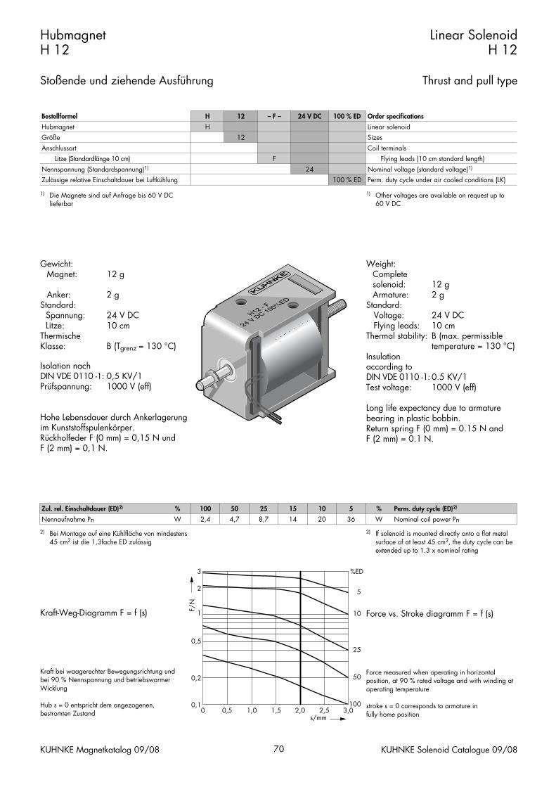
Force vs. Stroke diagramm F = f (s)
Force measured when operating in horizontal position, at 90 % rated voltage and with winding at operating temperature
stroke s = 0 corresponds to armature infully home position
Gewicht:Magnet: 12 g
Anker: 2 gStandard:
Spannung: 24 V DCLitze: 10 cm
Thermische Klasse: B (Tgrenz = 130 °C)
Isolation nachDIN VDE 0110 -1: 0,5 KV/1 Prüfspannung: 1000 V (eff)
Hohe Lebensdauer durch Ankerlagerungim Kunststoffspulenkörper.Rückholfeder F (0 mm) = 0,15 N und F (2 mm) = 0,1 N.
Kraft-Weg-Diagramm F = f (s)
Kraft bei waagerechter Bewegungsrichtung undbei 90 % Nennspannung und betriebswarmerWicklung
Hub s = 0 entspricht dem angezogenen,bestromten Zustand
HubmagnetH 12
Stoßende und ziehende Ausführung
Linear SolenoidH 12
Thrust and pull type
KUHNKE Magnetkatalog 09/08 70 KUHNKE Solenoid Catalogue 09/08
Bestellformel H 12 – F – 24 V DC 100 % ED Order specifications
HubmagnetGröße
H12
Linear solenoidSizes
Anschlussart
Nennspannung (Standardspannung)1)
Zulässige relative Einschaltdauer bei Luftkühlung
Litze (Standardlänge 10 cm) F24
100 % ED
Coil terminalsFlying leads (10 cm standard length)
Nominal voltage (standard voltage)1)
Perm. duty cycle under air cooled conditions (LK)
H12 - F
24 V DC 100%ED
1) Die Magnete sind auf Anfrage bis 60 V DClieferbar
1) Other voltages are available on request up to 60 V DC
Zul. rel. Einschaltdauer (ED)2) % 100 50 25 15 10 5 % Perm. duty cycle (ED)2)
Nennaufnahme Pn W 2,4 4,7 8,7 14 20 36 W Nominal coil power Pn
2) Bei Montage auf eine Kühlfläche von mindestens 45 cm2 ist die 1,3fache ED zulässig
2) If solenoid is mounted directly onto a flat metal surface of at least 45 cm2, the duty cycle can be extended up to 1.3 x nominal rating
0 0,5 1,0 1,5 2,0 2,5 3,0s/mm
F/N
0,1
0,2
0,5
%ED
100
50
25
10
5
1
2
3

HubmagnetH 12
Stoßende und ziehende Ausführung
Linear SolenoidH 12
Thrust and pull type
KUHNKE Magnetkatalog 09/08 71 KUHNKE Solenoid Catalogue 09/08
6
100 + 15
5
4 2M2
16
12
186 ± 0,2
2 ± 0,2
30
4 +1
6
M2
7
Maße im bestromten Zustand
<–––––––Hubrichtung
Dimensions given with armature in fully home position<–––––––Direction of stroke
Kombimagnet H 12 Series H 12 combi type solenoid

Weight:Complete solenoid: appr. 65 gArmature: appr. 13 g
Standard:Voltage: 24 V DCFlying leads: 10 cm
Thermal stability: B (max. permissibletemperature = 130 °C)
Insulation groupaccording to: VDE 0110 B 75Test voltage: 2500 V (eff)
Long life expectancy due to armaturebearing in platic bobbin.* On request, the solenoid can also besupplied with service-free armature bearing (plain bearing) for maximumdurability.
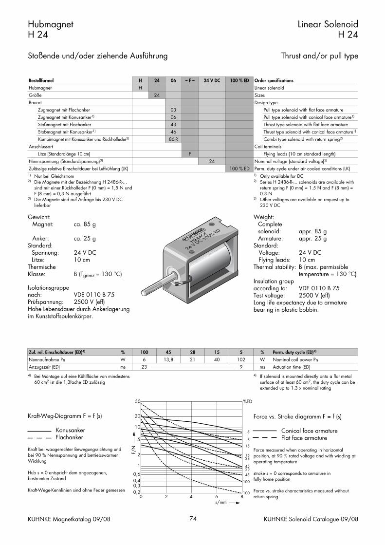
Force vs. Stroke diagramm F = f (s)
Conical face armatureFlat face armature
Force measured when operating in horizontal position, at 90 % rated voltage and with winding at operating temperature
stroke s = 0 corresponds to armature infully home position
Force vs. stroke characteristics measured withoutreturn spring
Gewicht:Magnet: ca. 65 g
Anker: ca. 13 gStandard:
Spannung: 24 V DCLitze: 10 cm
Thermische Klasse: B (Tgrenz = 130 °C)
Isolationsgruppenach: VDE 0110 B 75Prüfspannung: 2500 V (eff)
Hohe Lebensdauer durch Ankerlagerungim Kunststoffspulenkörper.* Auf Anfrage ist dieser Magnet auchmit wartungsfreier Ankerlagerung (Gleit-lager) für höchste Lebensdauer lieferbar.
Kraft-Weg-Diagramm F = f (s)
KonusankerFlachanker
Kraft bei waagerechter Bewegungsrichtung undbei 90 % Nennspannung und betriebswarmerWicklung
Hub s = 0 entspricht dem angezogenen,bestromten Zustand
Kraft-Wege-Kennlinien sind ohne Feder gemessen
HubmagnetH 22
Stoßende und/oder ziehende Ausführung
Linear SolenoidH 22
Thrust and/or pull type
KUHNKE Magnetkatalog 09/08 72 KUHNKE Solenoid Catalogue 09/08
Bestellformel H D* 22 06 – F – 24 V DC 100 % ED Order specifications
HubmagnetGleitlager
HD*
Linear solenoidPlain bearing
GrößeBauart
Zugmagnet mit FlachankerZugmagnet mit Konusanker1)
22
0306
SizesDesign type
Pull type solenoid with flat face armaturePull type solenoid with conical face armature1)
Anschlussart
Stoßmagnet mit FlachankerStoßmagnet mit Konusanker1)
Kombimagnet mit Konusanker und Rückholfeder2)
Nennspannung (Standardspannung)3)
Zulässige relative Einschaltdauer bei Luftkühlung
Litze (Standardlänge 10 cm)Flachstecker (optional)
4346
86-R
FA
Thrust type solenoid with flat face armatureThrust type solenoid with conical face armature1)
Coil terminalsCombi type solenoid with return spring2)
24100 % ED
Flying leads (10 cm standard length)Push-on connector (optional)
Nominal voltage (standard voltage)3)
Perm. duty cycle under air cooled conditions (LK)1) Nur bei Gleichstrom2) Die Magnete mit der Bezeichnung H 2286-R-...
sind mit einer Rückholfeder F (0 mm) = 1,5 N undF (5 mm) = 0,2 N ausgeführt
3) Die Magnete sind auf Anfrage bis 230 V DClieferbar
1) Only available for DC2) Series H 2286-R-... solenoids are available with
return spring F (0 mm) = 1.5 N and F (5 mm) =0.2 N
3) Other voltages are available on request up to230 V DC
Zul. rel. Einschaltdauer (ED)4) % 100 45 25 15 5 % Perm. duty cycle (ED)4)
Nennaufnahme PnAnzugszeit (ED)
Wms
5,224
10,2 19 29,5 757
Wms
Nominal coil power PnActuation time (ED)
4) Bei Montage auf eine Kühlfläche von mindestens 45 cm2 ist die 1,3fache ED zulässig
4) If solenoid is mounted directly onto a flat metal surface of at least 45 cm2, the duty cycle can be extended up to 1.3 x nominal rating
0 1 2 3 4 5s/mm
F/N
0,1
0,2
0,5
30 %ED
100
10025451525
5
15
45
1
23457
10
20

HubmagnetH 22
Stoßende und/oder ziehende Ausführung
Linear SolenoidH 22
Thrust and/or pull type
KUHNKE Magnetkatalog 09/08 73 KUHNKE Solenoid Catalogue 09/08
2515
20
M3 32
8
Ø8 2
48,5 0,5
8153,5
M3
Ø2
2515
20
M3 32
815
M3
64,525,5 0,3
15+1
M3
8
Maße im bestromten Zustand
–––––––>Hubrichtung
Maße im bestromten Zustand
–––––––>Hubrichtung
Dimensions given with armature in fully home position–––––––>Direction of stroke
Dimensions given with armature in fully home position–––––––>Direction of stroke
Zugmagnet H 2203/2206 Series H 2203/2206 pull type solenoid
Stoßmagnet H 2243/2246 Series H 2243/2246 thrust type solenoid
2515
20
M3 32
8
Ø8 2
74
8153,5
Ø2
15+1
M3
M3
25,5 0,3
Maße im bestromten Zustand
–––––––>Hubrichtung
Dimensions given with armature in fully home position–––––––>Direction of stroke
Kombimagnet H 2286-R mit Rückholfeder H 2286-R combi type solenoid with return spring
Weight:Complete solenoid: appr. 85 gArmature: appr. 25 g
Standard:Voltage: 24 V DCFlying leads: 10 cm
Thermal stability: B (max. permissibletemperature = 130 °C)
Insulation groupaccording to: VDE 0110 B 75Test voltage: 2500 V (eff)Long life expectancy due to armaturebearing in plastic bobbin.
Force vs. Stroke diagramm F = f (s)
Conical face armatureFlat face armature
Force measured when operating in horizontal position, at 90 % rated voltage and with winding at operating temperature
stroke s = 0 corresponds to armature infully home position
Force vs. stroke characteristics measured withoutreturn spring
Gewicht:Magnet: ca. 85 g
Anker: ca. 25 gStandard:
Spannung: 24 V DCLitze: 10 cm
Thermische Klasse: B (Tgrenz = 130 °C)
Isolationsgruppenach: VDE 0110 B 75Prüfspannung: 2500 V (eff)Hohe Lebensdauer durch Ankerlagerungim Kunststoffspulenkörper.
Kraft-Weg-Diagramm F = f (s)
KonusankerFlachanker
Kraft bei waagerechter Bewegungsrichtung undbei 90 % Nennspannung und betriebswarmerWicklung
Hub s = 0 entspricht dem angezogenen,bestromten Zustand
Kraft-Wege-Kennlinien sind ohne Feder gemessen
HubmagnetH 24
Stoßende und/oder ziehende Ausführung
Linear SolenoidH 24
Thrust and/or pull type
KUHNKE Magnetkatalog 09/08 74 KUHNKE Solenoid Catalogue 09/08
Bestellformel H 24 06 – F – 24 V DC 100 % ED Order specifications
HubmagnetGröße
H24
Linear solenoidSizes
BauartZugmagnet mit FlachankerZugmagnet mit Konusanker1)
Stoßmagnet mit Flachanker
030643
Design typePull type solenoid with flat face armaturePull type solenoid with conical face armature1)
Thrust type solenoid with flat face armature
Anschlussart
Stoßmagnet mit Konusanker1)
Kombimagnet mit Konusanker und Rückholfeder2)
Litze (Standardlänge 10 cm)Nennspannung (Standardspannung)3)
Zulässige relative Einschaltdauer bei Luftkühlung (LK)
4686-R
F24
Coil terminals
Thrust type solenoid with conical face armature1)
Combi type solenoid with return spring2)
Flying leads (10 cm standard length)
100 % EDNominal voltage (standard voltage)3)
Perm. duty cycle under air cooled conditions (LK)1) Nur bei Gleichstrom2) Die Magnete mit der Bezeichnung H 2486-R-...
sind mit einer Rückholfeder F (0 mm) = 1,5 N undF (8 mm) = 0,3 N ausgeführt
3) Die Magnete sind auf Anfrage bis 230 V DClieferbar
1) Only available for DC2) Series H 2486-R-... solenoids are available with
return spring F (0 mm) = 1.5 N and F (8 mm) =0.3 N
3) Other voltages are available on request up to230 V DC
Zul. rel. Einschaltdauer (ED)4) % 100 45 28 15 5 % Perm. duty cycle (ED)4)
Nennaufnahme PnAnzugszeit (ED)
Wms
623
13,8 21 40 1029
Wms
Nominal coil power PnActuation time (ED)
4) Bei Montage auf eine Kühlfläche von mindestens 60 cm2 ist die 1,3fache ED zulässig
4) If solenoid is mounted directly onto a flat metal surface of at least 60 cm2, the duty cycle can be extended up to 1.3 x nominal rating
0 2 4 6 8s/mm
F/N
0,30,2
0,40,6
1
2
50 %ED
100
100
28
28
45
45
15
5
55
10
20
15

HubmagnetH 24
Stoßende und/oder ziehende Ausführung
Linear SolenoidH 24
Thrust and/or pull type
KUHNKE Magnetkatalog 09/08 75 KUHNKE Solenoid Catalogue 09/08
25
19,5
824M3 ≤0,5
Ø6,
2
14
4
Ø3
4090,552
Ø10 3
20,5
25,5 0,34066,5
10+1M
3
25
19,5
824
14 Ø10
M3 ≤0,5
Ø6,
2
20,5
Maße im bestromten Zustand
–––––––>Hubrichtung
Maße im bestromten Zustand
–––––––>Hubrichtung
Dimensions given with armature in fully home position–––––––>Direction of stroke
Dimensions given with armature in fully home position–––––––>Direction of stroke
Zugmagnet H 2403/2406 Series H 2403/2406 pull type solenoid
Stoßmagnet H 2443/2446 Series H 2443/2446 thrust type solenoid
25
19,5
824M3 ≤0,5
14
4
409
Ø10 3
25,5 0,3
M310+1
77,5
Ø6,
2
Ø3
20,5
Maße im bestromten Zustand
–––––––>Hubrichtung
Dimensions given with armature in fully home position–––––––>Direction of stroke
Kombimagnet H 2486-R mit Rückholfeder H 2486-R combi type solenoid with return spring

Weight:Complete solenoid: appr. 90 gArmature: appr. 17 g
Standard:Voltage: 24 V DCFlying leads: 10 cm
Thermal stability: B (max. permissibletemperature = 130 °C)
Insulation groupaccording to: VDE 0110 C 36Test voltage: 2500 V (eff)Long life expectancy due to armature bearing in plastic bobbin.* On request, the solenoid can also besupplied with service-free armature bearing (plain bearing) for maximumdurability.
Force vs. Stroke diagramm F = f (s)
Conical face armatureFlat face armature
Force measured when operating in horizontal position, at 90 % rated voltage and with winding at operating temperature
stroke s = 0 corresponds to armature infully home position
Force vs. stroke characteristics measured withoutreturn spring
Gewicht:Magnet: ca. 90 g
Anker: ca. 17 gStandard:
Spannung: 24 V DCLitze: 10 cm
Thermische Klasse: B (Tgrenz = 130 °C)
Isolationsgruppenach: VDE 0110 C 36Prüfspannung: 2500 V (eff)Hohe Lebensdauer durch Ankerlagerungim Kunststoffspulenkörper.* Auf Anfrage ist dieser Magnet auchmit wartungsfreier Ankerlagerung (Gleit-lager) für höchste Lebensdauer lieferbar.
Kraft-Weg-Diagramm F = f (s)
KonusankerFlachanker
Kraft bei waagerechter Bewegungsrichtung undbei 90 % Nennspannung und betriebswarmerWicklung
Hub s = 0 entspricht dem angezogenen,bestromten Zustand
Kraft-Wege-Kennlinien sind ohne Feder gemessen
HubmagnetH 32
Stoßende und/oder ziehende Ausführung
Linear SolenoidH 32
Thrust and/or pull type
KUHNKE Magnetkatalog 09/08 76 KUHNKE Solenoid Catalogue 09/08
Bestellformel H D* 32 06 – F – 24 V DC 100 % ED Order specifications
HubmagnetGleitlager
HD*
Linear solenoidPlain bearing
GrößeBauart
Zugmagnet mit FlachankerZugmagnet mit Konusanker1)
32
0306
SizesDesign type
Pull type solenoid with flat face armaturePull type solenoid with conical face armature1)
Anschlussart
Stoßmagnet mit FlachankerStoßmagnet mit Konusanker1)
Kombimagnet mit Konusanker und Rückholfeder2)
Nennspannung (Standardspannung)3)
Zulässige relative Einschaltdauer bei Luftkühlung (LK)
Litze (Standardlänge 10 cm)Flachstecker (optional)
4346
86-R
FA
Thrust type solenoid with flat face armatureThrust type solenoid with conical face armature1)
Coil terminalsCombi type solenoid with return spring2)
24100 % ED
Flying leads (10 cm standard length)Push-on connector (optional)
Nominal voltage (standard voltage)3)
Perm. duty cycle under air cooled conditions (LK)
1) Nur bei Gleichstrom2) Die Magnete mit der Bezeichnung H 3286-R-...
sind mit einer Rückholfeder F (0 mm) = 0,8 N undF (5 mm) = 0,38 N ausgeführt
3) Die Magnete sind auf Anfrage bis 230 V DClieferbar
1) Only available for DC2) Series H 3286-R-... solenoids are available with
return spring F (0 mm) = 0.8 N and F (5 mm) =0.38 N
3) Other voltages are available on request up to230 V DC
Zul. rel. Einschaltdauer (ED)4) % 100 50 25 16 6 % Perm. duty cycle (ED)4)
Nennaufnahme PnAnzugszeit (ED)
Wms
5,221
9,6 18,2 28,5 718
Wms
Nominal coil power PnActuation time (ED)
4) Bei Montage auf eine Kühlfläche von mindestens 70 cm2 ist die 1,3fache ED zulässig
4) If solenoid is mounted directly onto a flat metal surface of at least 70 cm2, the duty cycle can be extended up to 1.3 x nominal rating
0 1 2 3 4 5s/mm
F/N
0,1
0,20,30,40,60,8
30 %ED
100
50100
25
5016
6
166
25
1
23468
10
20
HubmagnetH 32
Stoßende und/oder ziehende Ausführung
Linear SolenoidH 32
Thrust and/or pull type
KUHNKE Magnetkatalog 09/08 77 KUHNKE Solenoid Catalogue 09/08
4
Ø3
Ø10
9
3
30,5
617
18
M3
30
42,5±0,5
28
M3
20
15+1
M3
30,5
617
Ø10
M3
30
25,5±0,3
57
28
18
M3
20
Maße im bestromten Zustand
–––––––>Hubrichtung
Maße im bestromten Zustand
–––––––>Hubrichtung
Dimensions given with armature in fully home position–––––––>Direction of stroke
Dimensions given with armature in fully home position–––––––>Direction of stroke
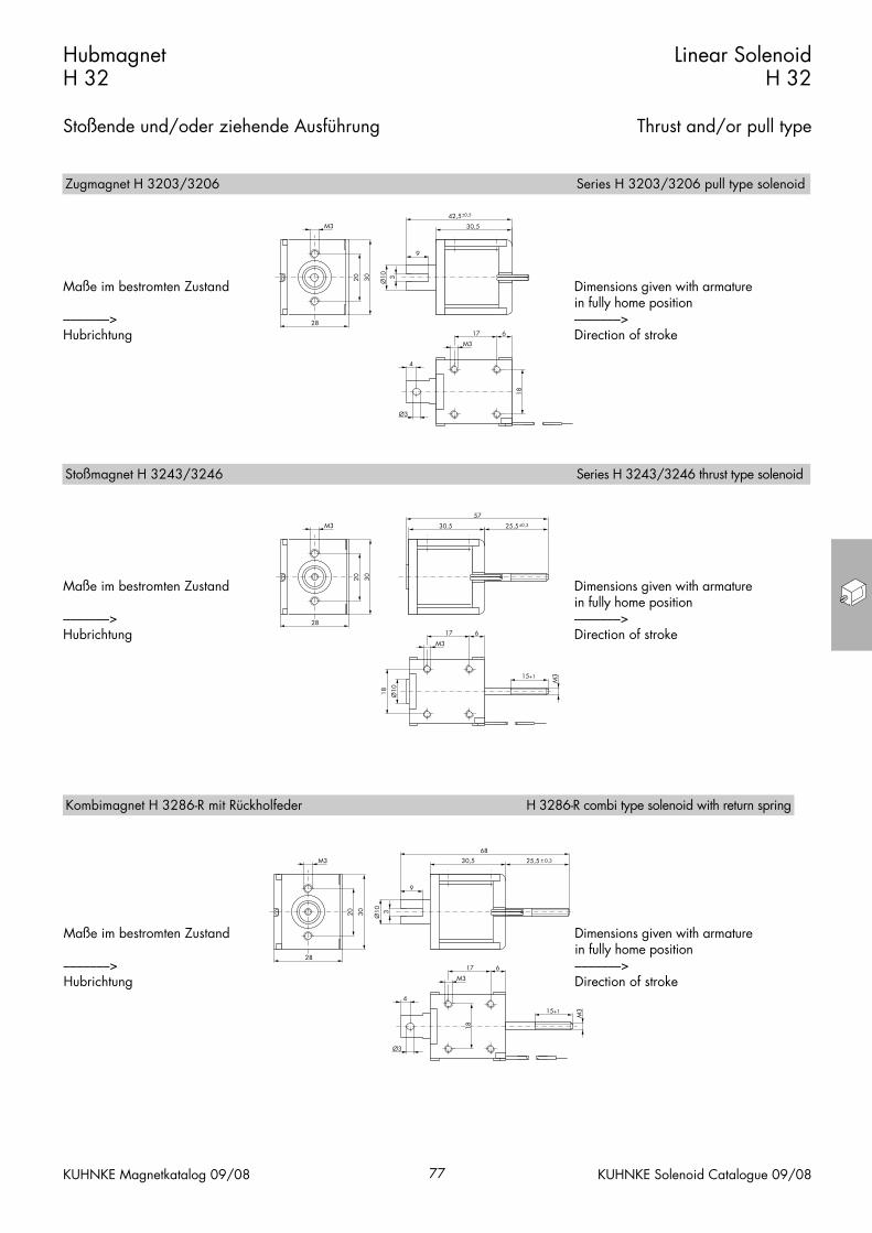
Zugmagnet H 3203/3206 Series H 3203/3206 pull type solenoid
Stoßmagnet H 3243/3246 Series H 3243/3246 thrust type solenoid
68
28
M3
20
25,5 0,3
15+1
M3
4
Ø3
Ø10
9
3
617
M3
30
30,5
18
Maße im bestromten Zustand
–––––––>Hubrichtung
Dimensions given with armature in fully home position–––––––>Direction of stroke
Kombimagnet H 3286-R mit Rückholfeder H 3286-R combi type solenoid with return spring

Weight:Complete solenoid: appr. 140 gArmature: appr. 32 g
Standard:Voltage: 24 V DCFlying leads: 10 cm
Thermal stability: B (max. permissibletemperature = 130 °C)
Insulation groupaccording to: VDE 0110 1.5 KV/3Test voltage: 2500 V (eff)Long life expectancy due to armaturebearing in plastic bobbin.* On request, the solenoid can also besupplied with service-free armature bea-ring (plain bearing) for maximumdurability.
Force vs. Stroke diagramm F = f (s)
Conical face armatureFlat face armature
Force measured when operating in horizontal position, at 90 % rated voltage and with winding at operating temperature
stroke s = 0 corresponds to armature infully home position
Force vs. stroke characteristics measured withoutreturn spring
Gewicht:Magnet: ca. 140 g
Anker: ca. 32 gStandard:
Spannung: 24 V DCLitze: 10 cm
Thermische Klasse: B (Tgrenz = 130 °C)
Isolationsgruppenach: VDE 0110 1,5 KV/3Prüfspannung: 2500 V (eff)Hohe Lebensdauer durch Ankerlagerungim Kunststoffspulenkörper.* Auf Anfrage ist dieser Magnet auchmit wartungsfreier Ankerlagerung (Gleit-lager) für höchste Lebensdauer lieferbar.
Kraft-Weg-Diagramm F = f (s)
KonusankerFlachanker
Kraft bei waagerechter Bewegungsrichtung undbei 90 % Nennspannung und betriebswarmerWicklung
Hub s = 0 entspricht dem angezogenen,bestromten Zustand
Kraft-Wege-Kennlinien sind ohne Feder gemessen
HubmagnetH 34
Stoßende und/oder ziehende Ausführung
Linear SolenoidH 34
Thrust and/or pull type
KUHNKE Magnetkatalog 09/08 78 KUHNKE Solenoid Catalogue 09/08
Bestellformel H D* 34 06 – F – 24 V DC 100 % ED Order specifications
HubmagnetGleitlager
HD*
Linear solenoidPlain bearing
GrößeBauart
Zugmagnet mit FlachankerZugmagnet mit Konusanker1)
34
0306
SizesDesign type
Pull type solenoid with flat face armaturePull type solenoid with conical face armature1)
Anschlussart
Stoßmagnet mit FlachankerStoßmagnet mit Konusanker1)
Kombimagnet mit Konusanker und Rückholfeder2)
Nennspannung (Standardspannung)3)
Zulässige relative Einschaltdauer bei Luftkühlung (LK)
Litze (Standardlänge 10 cm)
4346
86-R
F
Thrust type solenoid with flat face armatureThrust type solenoid with conical face armature1)
Coil terminalsCombi type solenoid with return spring2)
24100 % ED
Nominal voltage (standard voltage)3)
Flying leads (10 cm standard length)
Perm. duty cycle under air cooled conditions (LK)
1) Nur bei Gleichstrom2) Die Magnete mit der Bezeichnung H 3486-R- ...
sind mit einer Rückholfeder F (0 mm) = 1,25 Nund F (10 mm) = 0,75 N ausgeführt
3) Die Magnete sind auf Anfrage bis 230 V DClieferbar
1) Only available for DC2) Series H 3486-R-... solenoids are available with
return spring F (0 mm) = 1.25 N and F (10 mm)= 0.75 N
3) Other voltages are available on request up to230 V DC
Zul. rel. Einschaltdauer (ED)4) % 100 35 25 15 5 % Perm. duty cycle (ED)4)
Nennaufnahme PnAnzugszeit (ED)
Wms
845
23 30 57 14416
Wms
Nominal coil power PnActuation time (ED)
4) Bei Montage auf eine Kühlfläche von mindestens 100 cm2 ist die 1,3fache ED zulässig
4) If solenoid is mounted directly onto a flat metal surface of at least 100 cm2, the duty cycle can beextended up to 1.3 x nominal rating
0 2 4 6 8 10 120,1
0,2
0,5
%ED
100
1
2
57
10
203050
3525
15
55
s/mm
F/N

HubmagnetH 34
Stoßende und/oder ziehende Ausführung
Linear SolenoidH 34
Thrust and/or pull type
KUHNKE Magnetkatalog 09/08 79 KUHNKE Solenoid Catalogue 09/08
4
32 9
Ø3
M3
18
Ø12
9
3
49,5
60±0,5
30
26
M3
20
49,5 26
77,4 (H 3443)76,9 (H 3446)
±0,3
30
26
M3
20
10+1
M3
Ø12
32 9M3
18
Maße im bestromten Zustand
–––––––>Hubrichtung
Maße im bestromten Zustand
–––––––>Hubrichtung
Dimensions given with armature in fully home position–––––––>Direction of stroke
Dimensions given with armature in fully home position–––––––>Direction of stroke
Zugmagnet H 3403/3406 Series H 3403/3406 pull type solenoid
Stoßmagnet H 3443/3446 Series H 3443/3446 thrust type solenoid
4
32 9
Ø3
M3
18
Ø12
9
3
49,5
86
30
26
M3
20
26 0,3
10+1
M3
Maße im bestromten Zustand
–––––––>Hubrichtung
Dimensions given with armature in fully home position–––––––>Direction of stroke
Kombimagnet H 3486-R mit Rückholfeder H 3486-R combi type solenoid with return spring
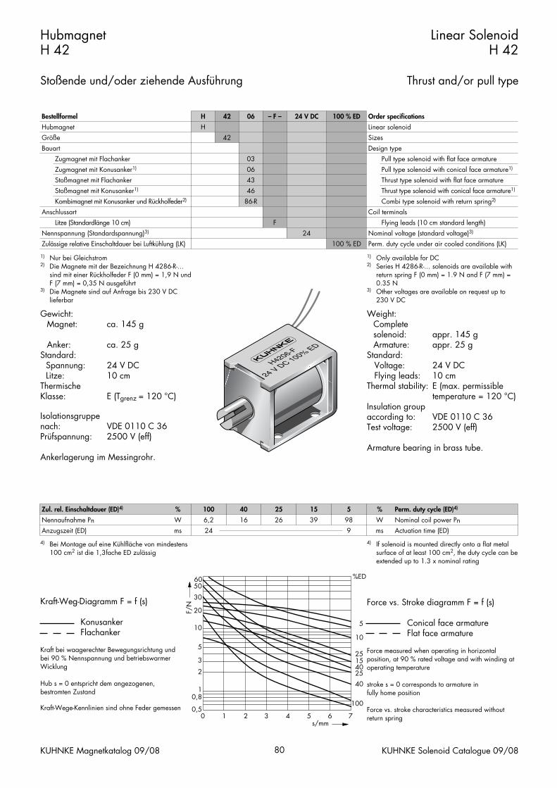
Weight:Complete solenoid: appr. 145 gArmature: appr. 25 g
Standard:Voltage: 24 V DCFlying leads: 10 cm
Thermal stability: E (max. permissibletemperature = 120 °C)
Insulation groupaccording to: VDE 0110 C 36Test voltage: 2500 V (eff)
Armature bearing in brass tube.
Force vs. Stroke diagramm F = f (s)
Conical face armatureFlat face armature
Force measured when operating in horizontal position, at 90 % rated voltage and with winding at operating temperature
stroke s = 0 corresponds to armature infully home position
Force vs. stroke characteristics measured withoutreturn spring
Gewicht:Magnet: ca. 145 g
Anker: ca. 25 gStandard:
Spannung: 24 V DCLitze: 10 cm
Thermische Klasse: E (Tgrenz = 120 °C)
Isolationsgruppenach: VDE 0110 C 36Prüfspannung: 2500 V (eff)
Ankerlagerung im Messingrohr.
Kraft-Weg-Diagramm F = f (s)
KonusankerFlachanker
Kraft bei waagerechter Bewegungsrichtung undbei 90 % Nennspannung und betriebswarmerWicklung
Hub s = 0 entspricht dem angezogenen,bestromten Zustand
Kraft-Wege-Kennlinien sind ohne Feder gemessen
HubmagnetH 42
Stoßende und/oder ziehende Ausführung
Linear SolenoidH 42
Thrust and/or pull type
KUHNKE Magnetkatalog 09/08 80 KUHNKE Solenoid Catalogue 09/08
Bestellformel H 42 06 – F – 24 V DC 100 % ED Order specifications
HubmagnetGröße
H42
Linear solenoidSizes
BauartZugmagnet mit FlachankerZugmagnet mit Konusanker1)
Stoßmagnet mit Flachanker
030643
Design typePull type solenoid with flat face armaturePull type solenoid with conical face armature1)
Thrust type solenoid with flat face armature
Anschlussart
Stoßmagnet mit Konusanker1)
Kombimagnet mit Konusanker und Rückholfeder2)
Litze (Standardlänge 10 cm)Nennspannung (Standardspannung)3)
Zulässige relative Einschaltdauer bei Luftkühlung (LK)
4686-R
F24
Coil terminals
Thrust type solenoid with conical face armature1)
Combi type solenoid with return spring2)
Flying leads (10 cm standard length)
100 % EDNominal voltage (standard voltage)3)
Perm. duty cycle under air cooled conditions (LK)
1) Nur bei Gleichstrom2) Die Magnete mit der Bezeichnung H 4286-R-...
sind mit einer Rückholfeder F (0 mm) = 1,9 N undF (7 mm) = 0,35 N ausgeführt
3) Die Magnete sind auf Anfrage bis 230 V DClieferbar
1) Only available for DC2) Series H 4286-R-... solenoids are available with
return spring F (0 mm) = 1.9 N and F (7 mm) =0.35 N
3) Other voltages are available on request up to230 V DC
Zul. rel. Einschaltdauer (ED)4) % 100 40 25 15 5 % Perm. duty cycle (ED)4)
Nennaufnahme PnAnzugszeit (ED)
Wms
6,224
16 26 39 989
Wms
Nominal coil power PnActuation time (ED)
4) Bei Montage auf eine Kühlfläche von mindestens 100 cm2 ist die 1,3fache ED zulässig
4) If solenoid is mounted directly onto a flat metal surface of at least 100 cm2, the duty cycle can beextended up to 1.3 x nominal rating
0 1 2 3 4 5 6 7s/mm
F/N
0,5
10,8
2
3
60 %ED
100
4025401525
10
5
5
10
20
30
50
HubmagnetH 42
Stoßende und/oder ziehende Ausführung
Linear SolenoidH 42
Thrust and/or pull type
KUHNKE Magnetkatalog 09/08 81 KUHNKE Solenoid Catalogue 09/08
35
31(34 bei/at ≥ 60 V)
M3
25
36
9
Ø10 3
48 ±0,5
17 12
Ø3
18
4
M335
31(34 bei/at ≥ 60 V)
M3
25
36 25,5±0,3
17 12
M3
18
15+1
M3
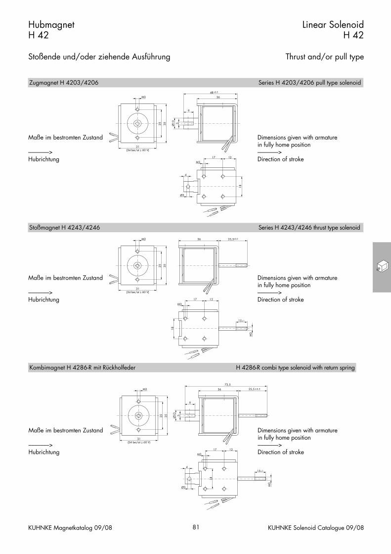
Maße im bestromten Zustand
–––––––>Hubrichtung
Maße im bestromten Zustand
–––––––>Hubrichtung
Dimensions given with armature in fully home position–––––––>Direction of stroke
Dimensions given with armature in fully home position–––––––>Direction of stroke
Zugmagnet H 4203/4206 Series H 4203/4206 pull type solenoid
Stoßmagnet H 4243/4246 Series H 4243/4246 thrust type solenoid
35
31(34 bei/at ≥ 60 V)
M3
25
36
9
Ø10 3
73,5
17 12
Ø3
4
M3
25,5 0,3
18
M3
15+1
Maße im bestromten Zustand
–––––––>Hubrichtung
Dimensions given with armature in fully home position–––––––>Direction of stroke
Kombimagnet H 4286-R mit Rückholfeder H 4286-R combi type solenoid with return spring

Weight:Complete solenoid: appr. 320 gArmature: appr. 45 g
Standard:Voltage: 24 V DCFlying leads: 10 cm
Thermal stability: B (max. permissibletemperature = 130 °C)
Insulation groupaccording to: VDE 0110 C 150Test voltage: 2500 V (eff)Long life expectancy due to armaturebearing in plastic bobbin.* On request, the solenoid can also besupplied with service-free armature bea-ring (plain bearing) for maximumdurability.
Force vs. Stroke diagramm F = f (s)
Conical face armatureFlat face armature
Force measured when operating in horizontal position, at 90 % rated voltage and with winding at operating temperature
stroke s = 0 corresponds to armature infully home position
Force vs. stroke characteristics measured withoutreturn spring
Gewicht:Magnet: ca. 320 g
Anker: ca. 45 gStandard:
Spannung: 24 V DCLitze: 10 cm
Thermische Klasse: B (Tgrenz = 130 °C)
Isolationsgruppenach: VDE 0110 C 150Prüfspannung: 2500 V (eff)Hohe Lebensdauer durch Ankerlagerungim Kunststoffspulenkörper.* Auf Anfrage ist dieser Magnet auchmit wartungsfreier Ankerlagerung (Gleit-lager) für höchste Lebensdauer lieferbar.
Kraft-Weg-Diagramm F = f (s)
KonusankerFlachanker
Kraft bei waagerechter Bewegungsrichtung undbei 90 % Nennspannung und betriebswarmerWicklung
Hub s = 0 entspricht dem angezogenen,bestromten Zustand
Kraft-Wege-Kennlinien sind ohne Feder gemessen
HubmagnetH 62
Stoßende und/oder ziehende Ausführung
Linear SolenoidH 62
Thrust and/or pull type
KUHNKE Magnetkatalog 09/08 82 KUHNKE Solenoid Catalogue 09/08
Bestellformel H D* 62 06 – F – 24 V DC 100 % ED Order specifications
HubmagnetGleitlager
HD*
Linear solenoidPlain bearing
GrößeBauart
Zugmagnet mit FlachankerZugmagnet mit Konusanker1)
62
0306
SizesDesign type
Pull type solenoid with flat face armaturePull type solenoid with conical face armature1)
Anschlussart
Stoßmagnet mit FlachankerStoßmagnet mit Konusanker1)
Kombimagnet mit Konusanker und Rückholfeder2)
Nennspannung (Standardspannung)3)
Zulässige relative Einschaltdauer bei Luftkühlung (LK)
Litze (Standardlänge 10 cm)Flachstecker (optional)
4346
86-R
FA
Thrust type solenoid with flat face armatureThrust type solenoid with conical face armature1)
Coil terminalsCombi type solenoid with return spring2)
24100 % ED
Flying leads (10 cm standard length)Push-on connector (optional)
Nominal voltage (standard voltage)3)
Perm. duty cycle under air cooled conditions (LK)1) Nur bei Gleichstrom2) Die Magnete mit der Bezeichnung H 6286-R-...
sind mit einer Rückholfeder F (0 mm) = 2,5 N undF (15 mm) = 0,75 N ausgeführt
3) Die Magnete sind auf Anfrage bis 230 V DClieferbar
1) Only available for DC2) Series H 6286-R-... solenoids are available with
return spring F (0 mm) = 2.5 N and F (15 mm) =0.75 N
3) Other voltages are available on request up to230 V DC
Zul. rel. Einschaltdauer (ED)4) % 100 50 30 15 5 % Perm. duty cycle (ED)4)
Nennaufnahme PnAnzugszeit (ED)
Wms
1145
20 33 63 15616
Wms
Nominal coil power PnActuation time (ED)
4) Bei Montage auf eine Kühlfläche von mindestens 160 cm2 ist die 1,3fache ED zulässig
4) If solenoid is mounted directly onto a flat metal surface of at least 160 cm2, the duty cycle can beextended up to 1.3 x nominal rating
0 5 10 15 20s/mm
F/N
0,81
2345
8
100 %ED
1005050
3015
5510
20
806050
30

HubmagnetH 62
Stoßende und/oder ziehende Ausführung
Linear SolenoidH 62
Thrust and/or pull type
KUHNKE Magnetkatalog 09/08 83 KUHNKE Solenoid Catalogue 09/08
Ø13
10
5,5
50
63 ±0,5
4
Ø4
1225
27
M344
3834
27
M3
50 30,5±0,5
82,5
44
38
34
27
M3
Ø13
1225
27
M3
10+1
M4
Maße im bestromten Zustand
–––––––>Hubrichtung
Maße im bestromten Zustand
–––––––>Hubrichtung
Dimensions given with armature in fully home position–––––––>Direction of stroke
Dimensions given with armature in fully home position–––––––>Direction of stroke
Zugmagnet H 6203/6206 Series H 6203/6206 pull type solenoid
Stoßmagnet H 6243/6246 Series H 6243/6246 thrust type solenoid
Ø13
10
5,5
50
93,5
4
Ø4
1225
M3
27
44
38
34
27
M3 30,5 0,5
10+1
M4
Maße im bestromten Zustand
–––––––>Hubrichtung
Dimensions given with armature in fully home position–––––––>Direction of stroke
Kombimagnet H 6286-R mit Rückholfeder Series H 6286-R combi type solenoid with return spring
Diese Produkte entsprechen der Niederspan-nungsrichtlinie 73/23/EWG. Die Einhaltungder EMV-Richtlinie 89/336/EWG ist mit ent-sprechenden Schaltgeräten bzw-. Ansteue-rungen vom Anwender sicherzustellen.
Dieser Katalog ist vor allem für denKonstrukteur, Projekteur und Geräteentwicklerbestimmt. Er gibt keine Auskunft überLiefermöglichkeiten.Die angegebenen Daten dienen allein derProduktbeschreibung und sind nicht alsgarantierte Beschaffenheit des Produktes imRechtssinne aufzufassen.Beschaffenheitsvereinbarungen bleiben demkonkreten Vertragsverhältnis vorbehalten.Etwaige Schadensersatzansprüche gegen uns– gleich aus welchem Rechtsgrund – sind aus-geschlossen, soweit uns nicht Vorsatz odergrobe Fahrlässigkeit trifft. Vervielfältigungen,auch auszugsweise, dürfen nur mitGenehmigung des Autors vorgenommen werden. Änderungen, Auslassungen undIrrtümer vorbehalten.
These products comply with low voltage regulations 73/23/EWG. The user must ensure that EMC regulation 89/336/EWG iscomplied with using the appropriate switchingdevices or drivers respectively.
This catalogue is primarily intended for thedesign and development engineer. It is not an indication of delivery possibilities.The indicated data only serve the descriptionof the product, they are not to be understoodas the guaranteed quality of the product inlegal terms. Agreements as to the quality of the product arereserved to the proper contractual relationship.Claims of damages against us – on whatevergrounds – are excluded, except in instances ofdeliberate intent or gross negligence on ourpart. Reproduction, even of extracts only withthe author’s approval. We reserve the rights of modification, omission,error.

Weight:Complete solenoid: appr. 60 gArmature: appr. 12 g
Standard:Voltage: 24 V DCFlying leads: 10 cm
Thermal stability: B (max. permissibletemperature = 130 °C)
Insulation groupaccording to: VDE 0110 C 300Test voltage: 800 V (eff)
Service-free armature bearing (plain bearing) for maximum durability.Solenoids with order specification RM20-R-... are available with return spring F (0mm) = 1.2 N and F (3 mm) = 0.5 N.
Force vs. Stroke diagramm F = f (s)
Force measured when operating in horizontal position, at 90 % rated voltage and with winding at operating temperature
stroke s = 0 corresponds to armature infully home position
Gewicht:Magnet: ca. 60 g
Anker: ca. 12 gStandard:
Spannung: 24 V DCLitze: 10 cm
Thermische Klasse: B (Tgrenz = 130 °C)
Isolationsgruppenach: VDE 0110 C 300Prüfspannung: 800 V (eff)
Wartungsfreie Ankerlagerung (Gleitlager) für höchste Lebensdauer. Die Magnete mit der BestellbezeichnungRM20-R-... sind mit einer internenRückholfeder F (0 mm) = 1,2 N und F (3 mm) = 0,5 N ausgeführt.
Kraft-Weg-Diagramm F = f (s)
Kraft bei waagerechter Bewegungsrichtung undbei 90 % Nennspannung und betriebswarmerWicklung
Hub s = 0 entspricht dem angezogenen,bestromten Zustand
Hochleistungs-HubmagnetRM 20
Stoßende und ziehende Ausführung
Heavy Duty Linear SolenoidRM 20
Thrust and pull type
KUHNKE Magnetkatalog 09/08 110 KUHNKE Solenoid Catalogue 09/08
Bestellformel RM 20 – R – – F – 24 V DC 100 % ED Order specifications
HubmagnetBauart
RM20
Linear solenoidDesign type
RückholfederAnschlussart
Nennspannung (Standardspannung)1)
Litze (Standardlänge 10 cm)
R
F24
Return springCoil terminals
Nominal voltage (standard voltage)1)
Flying leads (10 cm standard length)
Zulässige relative Einschaltdauer bei Luftkühlung (LK) 100 % ED Perm. duty cycle under air cooled conditions (LK)1) Die Magnete sind auf Anfrage bis 60 V DC
lieferbar
1) Other voltages are available on request up to 60 V DC
Zul. rel. Einschaltdauer (ED)2) % 100 45 25 15 5 % Perm. duty cycle (ED)2)
Nennaufnahme PnAnzugszeit (ED)
Wms
3,911
8 13,5 21 595
Wms
Nominal coil power PnActuation time (ED)
2) Bei Montage auf eine Kühlfläche ist eine höhere ED zulässig (bitte anfragen)
2) If solenoid is mounted directly onto a flat metal surface, an increase in relative duty cycle is permissible (please ask for advice)
0 1 2 3s/mm
F/N
1
2
5
100 %ED
100
45
2515
510
20
50
Ø20
Ø12Ø16
SW14
66,5
M3
28
8+1
127
8+1
82
M3
M6
Maße im bestromten Zustand
–––––––>Hubrichtung
Dimensions given with armature in fullyhome position–––––––>Direction of stroke

Weight:Complete solenoid: appr. 117 gArmature: appr. 24 g
Standard:Voltage: 24 V DCFlying leads: 10 cm
Thermal stability: B (max. permissibletemperature = 130 °C)
Insulation groupaccording to: VDE 0110 B 150Test voltage: 800 V (eff)Service-free armature bearing (plainbearing) for maximum durability.Linear force vs. stroke output optional.Solenoids with order specification RM26-R-... are available with returnspring F (0 mm) = 0.8 N and F (4 mm) = 0.5 N.
Force vs. Stroke diagramm F = f (s)
Force measured when operating in horizontal position, at 90 % rated voltage and with winding at operating temperature
stroke s = 0 corresponds to armature infully home position
Gewicht:Magnet: ca. 117 g
Anker: ca. 24 gStandard:
Spannung: 24 V DCLitze: 10 cm
Thermische Klasse: B (Tgrenz = 130 °C)
Isolationsgruppenach: VDE 0110 B 150Prüfspannung: 800 V (eff)Wartunsfreie Ankerlagerung (Gleitlager)für höchste Lebensdauer.Waagerechte Kennlinie auf Anfrage.Die Magnete mit der BestellbezeichnungRM26-R-... sind mit einer internenRückholfeder F (0 mm) = 0,8 N und F (4 mm) = 0,5 N ausgeführt.
Kraft-Weg-Diagramm F = f (s)
Kraft bei waagerechter Bewegungsrichtung undbei 90 % Nennspannung und betriebswarmerWicklung
Hub s = 0 entspricht dem angezogenen,bestromten Zustand
Hochleistungs-HubmagnetRM 26
Stoßende und ziehende Ausführung
Heavy Duty Linear SolenoidRM 26
Thrust and pull type
KUHNKE Magnetkatalog 09/08 111 KUHNKE Solenoid Catalogue 09/08
Bestellformel RM 26 – R– – F – 24 V DC 100 % ED Order specifications
HubmagnetBauart
RM26
Linear solenoidDesign type
RückholfederAnschlussart
Nennspannung (Standardspannung)1)
Litze (Standardlänge 10 cm)
R
F24
Return springCoil terminals
Nominal voltage (standard voltage)1)
Flying leads (10 cm standard length)
Zulässige relative Einschaltdauer bei Luftkühlung (LK) 100 % ED Perm. duty cycle under air cooled conditions (LK)1) Die Magnete sind auf Anfrage bis 60 V DC
lieferbar1) Other voltages are available on request up to
60 V DC
Zul. rel. Einschaltdauer (ED)2) % 100 40 25 15 5 % Perm. duty cycle (ED)2)
Nennaufnahme Pn W 5,5 12,2 18,9 35,3 84 W Nominal coil power Pn2) Bei Montage auf eine Kühlfläche ist eine höhere
ED zulässig (bitte anfragen)
2) If solenoid is mounted directly onto a flat metal surface, an increase in relative duty cycle is permissible (please ask for advice)
0 1 2 3 4s/mm
F/N
1
2
3
5
100 %ED
100
40
2515
5
10
20
50
SW 1
7
Ø 17
Ø 19
Ø 26
M3
8 +1
7,5 30
2
10 13
8+1
M3
M10
72
Maße im bestromten Zustand
–––––––>Hubrichtung
Dimensions given with armature in fullyhome position–––––––>Direction of stroke

Weight:Complete solenoid: appr. 235 gArmature: appr. 40 g
Standard:Voltage: 24 V DCFlying leads: 10 cm
Thermal stability: B (max. permissibletemperature = 130 °C)
Insulation groupaccording to: VDE 0110 B 150Test voltage: 800 V (eff)
Service-free armature bearing (plain bearing) for maximum durability.
Linear force vs. stroke output optional.Solenoids with order specification
RM32-R-... are available with returnspring F (0 mm) = 3.0 N and
F (8 mm) = 1.5 N.
Force vs. Stroke diagramm F = f (s)
Force measured when operating in horizontal position, at 90 % rated voltage and with winding at operating temperature
stroke s = 0 corresponds to armature infully home position
Gewicht:Magnet: ca. 235 g
Anker: ca. 40 gStandard:
Spannung: 24 V DCLitze: 10 cm
Thermische Klasse: B (Tgrenz = 130 °C)
Isolationsgruppenach: VDE 0110 B 150Prüfspannung: 800 V (eff)Wartungsfreie Ankerlagerung (Gleitlager) für höchste Lebensdauer.Waagerechte Kennlinie auf Anfrage.Die Magnete mit der BestellbezeichnungRM32-R-... sind mit einer internenRückholfeder F (0 mm) = 3,0 N und F (8 mm) = 1,5 N ausgeführt.
Kraft-Weg-Diagramm F = f (s)
Kraft bei waagerechter Bewegungsrichtung undbei 90 % Nennspannung und betriebswarmerWicklung
Hub s = 0 entspricht dem angezogenen,bestromten Zustand
Hochleistungs-HubmagnetRM 32
Stoßende und ziehende Ausführung
Heavy Duty Linear SolenoidRM 32
Thrust and pull type
KUHNKE Magnetkatalog 09/08 112 KUHNKE Solenoid Catalogue 09/08
Bestellformel RM 32 – R – – F – 24 V DC 100 % ED Order specifications
HubmagnetBauart
RM32
Linear solenoidDesign type
RückholfederAnschlussart
Litze (Standardlänge 10 cm)Gerätestecker 1)
R
FN
Return springCoil terminals
Flying leads (10 cm standard length)Plug 1)
Nennspannung (Standardspannung)2)
Zulässige relative Einschaltdauer bei Luftkühlung (LK)24
100 % EDNominal voltage (standard voltage)2)
Perm. duty cycle under air cooled conditions (LK)
RM 32-F
24VDC 100% ED
1) Passend für Steckhülsen 6,3 DIN 46247 und Ge-rätesteckdose Z 801 und Z 811 (s. Seite 132)
2) Die Magnete sind auf Anfrage bis 60 V DC lieferbar
1) Suits push-on connector 6.3 DIN 46247 andplug-in socket Z 801 and Z 811 (see page 132)
2) Other voltages are available on request up to 60 V DC
Zul. rel. Einschaltdauer (ED)2) % 100 70 45 25 15 5 % Perm. duty cycle (ED)2)
Nennaufnahme PnAnzugszeit (ED)
Wms
6,529
10 16 24 48 12211
Wms
Nominal coil power PnActuation time (ED)
2) Bei Montage auf eine Kühlfläche ist eine höhere ED zulässig (bitte anfragen)
2) If solenoid is mounted directly onto a flat metal surface, an increase in relative duty cycle is permissible (please ask for advice)
0 2 4 6 8s/mm
F/N
1
2
5
100 %ED
100
50
2515105
10
20
50
Ø1824
M3
94
M4
4510+1
24114 10+12
M4
Ø18
Ø32
Maße im bestromten Zustand
–––––––>Hubrichtung
Dimensions given with armature in fullyhome position–––––––>Direction of stroke

Coil terminals
Examples of design types:–––––––>Direction of stroke
Anschlussarten
Beispiele für Ausführungen:–––––––>Hubrichtung
Hochleistungs-HubmagneteRM 040 ... RM 100
Heavy Duty Linear SolenoidsRM 040 ... RM 100
KUHNKE Magnetkatalog 09/08 113 KUHNKE Solenoid Catalogue 09/08
–OBOO– –OBLO– –OBOR– –ORRO– –OROR–
–HBOO– –HBLO– –HBOL– –HRRO– –HROR–
Bestellformel RM 070 – W – O R O R – N – 24 V DC 100 % ED Order specifications
HubmagnetBauart ø mm
RM040
Linear solenoid seriesDesign type ø mm
050060070080
140 mm und 160 mm auf Anfrage
Waagerechte Kraft-Weg-KennlinieAusführung2)
Hubbegrenzung ohnemit
0901001401)
1601)
W
OH
140 mm and 160 mm optional
Horizontal frontal force vs. stroke outputDescription2)
Stroke limit withoutwith
Stößel rechts3)
beidseitigFlansch ohne
rechts3)
Faltenbalglinks4)
ohnerechts3)
links4) 5)
Anschlussartbeidseitig5)
Litze (Standardlänge 20 cm)(RM 040 Standard-länge 10 cm)
Nennspannung
Zulässige relative Einschaltdauer bei Luftkühlung (LK)
Gerätestecker6) 24 V DC205 V DC (an 230 V ACnach SI-Gleichrichter-brücke)
RB
ORL
ORL
Plunger
Flange
Gaiter
BF
N
Coil terminals
24205
100 % ED
Operating voltage
Perm. duty cycle under air cooled conditions (LK)
right hand side3)
both sideswithoutright hand side3)
left hand side4)
withoutright hand side3)
left hand side4) 5)
both sides5)
Flying leads (20 cm standard length)(RM 040 10 cm standard length)
Plug6) 24 V DC205 V DC (connected to230 V AC with SI- bridgerectifier)
1) 140 mm und 160 mm auf Anfrage2) Siehe unten3) Entgegengesetzt zur elektr.
Anschlussseite4) An der elektr. Anschlussseite5) Bei Magneten ≥ RM060 nur mit
Hubbegrenzung lieferbar6) Für Steckhülse 6,3 DIN 46247 und
Gerätesteckdose Z 801 und Z 811Zubehör siehe Seite 132-133
1) 140 mm and 160 mm optional2) See below3) Opposite to electrical connection4) Same side as electrical connection5) For solenoids ≥ RM060 available
with stroke limit only 6) For push-on connector 6.3 DIN 46247 and plug-
in socket Z 801 and Z 811Accessories see pages 132-133
N F
ca.1
2ca
.12
200
+15

Heavy duty linear solenoid RM 040
Weight:Complete solenoid: appr. 380 gArmature: appr. 60 g
Standard:Voltage: 24 V DCFlying leads: 10 cm
Thermal stability: F (max. permissibletemperature = 155 °C)
Insulation groupaccording to: VDE 0110 C 300Test voltage: 2500 V (eff)
Service-free armature bearing (plain bearing) for maximum durability. Stroke of version with standard strokelimiter: 8 mm.Return spring optional.
Force vs. Stroke diagramm F = f (s)
Force measured when operating in horizontal position, at 90 % rated voltage and with winding at operating temperature
stroke s = 0 corresponds to armature infully home position
Hochleistungs-Hubmagnet RM 040
Gewicht:Magnet: ca. 380 g
Anker: ca. 60 gStandard:
Spannung: 24 V DCLitze: 10 cm
Thermische Klasse: F (Tgrenz = 155 °C)
Isolationsgruppenach: VDE 0110 C 300Prüfspannung: 2500 V (eff)
Wartungsfreie Ankerlagerung (Gleitlager) für höchste Lebensdauer. Bei Ausführung mit Standard-Hub-begrenzung Hub 8 mm.In Sonderausführung mit eingebauterRückholfeder lieferbar.
Kraft-Weg-Diagramm F = f (s)
Kraft bei waagerechter Bewegungsrichtung undbei 90 % Nennspannung und betriebswarmerWicklung
Hub s = 0 entspricht dem angezogenen,bestromten Zustand
Hochleistungs-HubmagnetRM 040
Heavy Duty Linear SolenoidRM 040
KUHNKE Magnetkatalog 09/08 114 KUHNKE Solenoid Catalogue 09/08
RM040
24VDC100 %ED
Zul. rel. Einschaltdauer (ED)2) % 100 40 25 15 5 % Perm. duty cycle (ED)2)
Nennaufnahme PnAnzugszeit (ED)
Wms
1136
21 41 67 16111
Wms
Nominal coil power PnActuation time (ED)
2) Bei Montage auf eine Kühlfläche ist eine höhere ED zulässig (bitte anfragen)
2) If solenoid is mounted directly onto a flat metal surface, an increase in relative duty cycle is permissible (please ask for advice)
0 1 2 3 4 5 6 7 8 9 101
2
4
6
5
%ED
F/N
1008060
40
20
108
s/mm
100
40
25
15

Hochleistungs-HubmagnetRM 040
Heavy Duty Linear SolenoidRM 040
KUHNKE Magnetkatalog 09/08 115 KUHNKE Solenoid Catalogue 09/08
52
128
≤ Ø 26
745
39 34
3340
≤ Ø 26
≈ 20
Ø3,
5
≈ 20
M3
Ø22
Ø30
Ø40 19 30
Ø22
≈16
16+1
16+1
max
. 4m
ax. 4
4531
,7
M5
M5
5 ±0
,25
±0,2
65
≤ Ø26
58
M3
Ø30
3340
≤ Ø26
≈ 20
Ø3,
5
7≈
20
M3
Ø22
Ø30
Ø40 19 30
Ø 22
≈29
16+1
16+1
4
58
31,7
M5
M5
28
7
5 ±0
,25 ±0
,2
ohne Hubbegrenzung without stroke limiter
mit Hubbegrenzung with stroke limiter
Hub
richt
ung
Maß
e im
bes
trom
ten
Zusta
nd
Direction of stroke
Dim
ensions given with
armature in fully hom
e positionH
ubric
htun
g M
aße
im b
estro
mte
n Zu
stand
D
irection of strokeD
imensions given w
ith arm
ature in fully home position

Hochleistungs-Hubmagnet RM 050
Gewicht:Magnet: ca. 610 g
Anker: ca. 200 gStandard:
Spannung: 24 V DCLitze: 20 cm
Thermische Klasse: F (Tgrenz = 155 °C)
Isolationsgruppenach: VDE 0110 C 450Prüfspannung: 2500 V (eff)
Wartungsfreie Ankerlagerung (Gleitlager) für höchste Lebensdauer. Bei Ausführung mit Standard-Hubbegrenzung Hub 10 mm. In Sonderausführung mit eingebauterRückholfeder lieferbar.
Kraft-Weg-Diagramm F = f (s)
W = Waagerechte Kennlinie
Kraft bei waagerechter Bewegungsrichtung und bei 90 % Nennspannung und betriebswarmerWicklung
Hub s = 0 entspricht dem angezogenen, bestromten Zustand
Hochleistungs-HubmagnetRM 050
Heavy Duty Linear SolenoidRM 050
Heavy duty linear solenoid RM 050
Weight:Complete solenoid: appr. 610 gArmature: appr. 200 g
Standard:Voltage: 24 V DCFlying leads: 20 cm
Thermal stability: F (max. permissibletemperature = 155 °C)
Insulation groupaccording to: VDE 0110 C 450Test voltage: 2500 V (eff)
Service-free armature bearing (plain bearing) for maximum durability. Stroke of version with standard strokelimiter: 10 mm.Return spring optional.
Force vs. Stroke diagramm F = f (s)
W = horizontal characteristic
Force measured when operating in horizontal position, at 90 % rated voltage and winding at operating temperature
stroke s = 0 corresponds to armature in fully homeposition
KUHNKE Magnetkatalog 09/08 116 KUHNKE Solenoid Catalogue 09/08
Zul. rel. Einschaltdauer (ED)1) % 100 60 35 25 15 5 % Perm. duty Cycle (ED)1)
Nennaufnahme PnAnzugszeit (ED)
Wms
2040
30 55 70 115 30015
Wms
Nominal coil power PnActuation time (ED)
1) Bei Montage auf eine Kühlfläche ist eine höhereED zulässig (bitte anfragen)
1) If solenoid is mounted directly onto a flat metalsurface the duty cycle can be extended (pleaseask for advice)
0 2 4 6 8 10s/mm
F/N
10
20
50
1000 %ED
100
60
352515
5100
200
500

Hochleistungs-HubmagnetRM 050
Heavy Duty Linear SolenoidRM 050
KUHNKE Magnetkatalog 09/08 117 KUHNKE Solenoid Catalogue 09/08
M5
M5
Ø30
16+1
55
max
. 5M
4
~17
3019 50
42
5041
max
. 616
+1
≤ Ø 34
Ø34
50
736
5713
5
Ø4,
8
Ø50
Ø40
Ø30
32±
0,2
± 0,
2
Ø50
Ø40
M5
M5
Ø30
9
16+1
285
325
5M
4
~ 32
3019 50
42
65
16+1
Ø34
Ø34
65
7
72
Ø4,
8
Ø30
135
ohne Hubbegrenzung without stroke limiter
mit Hubbegrenzung with stroke limiter
Hub
richt
ung
Maß
e im
bes
trom
ten
Zusta
nd
Direction of stroke
Dim
ensions given with
armature in fully hom
e positionH
ubric
htun
g M
aße
im b
estro
mte
n Zu
stand
D
irection of strokeD
imensions given w
ith arm
ature in fully home position

Hochleistungs-Hubmagnet RM 060
Gewicht:Magnet: ca. 1300 g
Anker: ca. 250 gStandard:
Spannung: 24 V DCLitze: 20 cm
Thermische Klasse: F (Tgrenz = 155 °C)
Isolationsgruppenach: VDE 0110 C 450Prüfspannung: 2500 V (eff)
Wartungsfreie Ankerlagerung (Gleitlager) für höchste Lebensdauer. Bei Ausführung mit Standard-Hubbegrenzung Hub 12 mm. In Sonderausführung mit eingebauterRückholfeder lieferbar.
Kraft-Weg-Diagramm F = f (s)
W = Waagerechte Kennlinie
Kraft bei waagerechter Bewegungsrichtung und bei 90 % Nennspannung und betriebswarmerWicklung
Hub s = 0 entspricht dem angezogenen, bestromtenZustand
Hochleistungs-HubmagnetRM 060
Heavy Duty Linear SolenoidRM 060
Heavy duty linear solenoid RM 060
Weight:Complete solenoid: appr. 1300 gArmature: appr. 250 g
Standard:Voltage: 24 V DCFlying leads: 20 cm
Thermal stability: F (max. permissibletemperature = 155 °C)
Insulation groupaccording to: VDE 0110 C 450Test voltage: 2500 V (eff)
Service-free armature bearing (plain bearing) for maximum durability. Stroke of version with standard strokelimiter: 12 mm.Return spring optional.
Force vs. Stroke diagramm F = f (s)
W = horizontal characteristic
Force measured when operating in horizontal position, at 90 % rated voltage and winding at operating temperature
stroke s = 0 corresponds to armature in fully homeposition
KUHNKE Magnetkatalog 09/08 118 KUHNKE Solenoid Catalogue 09/08
Zul. rel. Einschaltdauer (ED)1) % 100 40 25 15 5 % Perm. duty Cycle (ED)1)
Nennaufnahme PnAnzugszeit (ED)
Wms
2545
60 98 150 38117
Wms
Nominal coil power PnActuation time (ED)
1) Bei Montage auf eine Kühlfläche ist eine höhereED zulässig (bitte anfragen)
1) If solenoid is mounted directly onto a flat metalsurface the duty cycle can be extended (pleaseask for advice)
0 5 10 12 15s/mm
F/N
10
20
50
1000 %ED
100
4025
15
5
100
200
500

Hochleistungs-HubmagnetRM 060
Heavy Duty Linear SolenoidRM 060
KUHNKE Magnetkatalog 09/08 119 KUHNKE Solenoid Catalogue 09/08
2934
M6
M6
Ø35
18+1
375
415
7
~19
64
718
+1
Ø36
65
8
72152
M6
M5
3019 67
54
Ø5,
8
Ø60
Ø45
Ø35
M6
M6
Ø35
10
18+1
295
415
7
~36
81
18+1
Ø36
82
8
89162
Ø36
M6
M5
3019 67
54
Ø5,
8
Ø60
Ø45
Ø35
ohne Hubbegrenzung without stroke limiter
mit Hubbegrenzung with stroke limiter
Hub
richt
ung
Maß
e im
bes
trom
ten
Zusta
nd
Direction of stroke
Dim
ensions given with
armature in fully hom
e positionH
ubric
htun
g M
aße
im b
estro
mte
n Zu
stand
D
irection of strokeD
imensions given w
ith arm
ature in fully home position

Hochleistungs-Hubmagnet RM 070
Gewicht:Magnet: ca. 2000 g
Anker: ca. 400 gStandard:
Spannung: 24 V DCLitze: 20 cm
Thermische Klasse: F (Tgrenz = 155 °C)
Isolationsgruppenach: VDE 0110 C 450Prüfspannung: 2500 V (eff)
Wartungsfreie Ankerlagerung (Gleitlager) für höchste Lebensdauer. Bei Ausführung mit Standard-Hubbegrenzung Hub 15 mm. In Sonderausführung mit eingebauterRückholfeder lieferbar.
Kraft-Weg-Diagramm F = f (s)
W = Waagerechte Kennlinie
Kraft bei waagerechter Bewegungsrichtung und bei 90 % Nennspannung und betriebswarmerWicklung
Hub s = 0 entspricht dem angezogenen, bestromtenZustand
Hochleistungs-HubmagnetRM 070
Heavy Duty Linear SolenoidRM 070
Heavy duty linear solenoid RM 070
Weight:Complete solenoid: appr. 2000 gArmature: appr. 400 g
Standard:Voltage: 24 V DCFlying leads: 20 cm
Thermal stability: F (max. permissibletemperature = 155 °C)
Insulation groupaccording to: VDE 0110 C 450Test voltage: 2500 V (eff)
Service-free armature bearing (plain bearing) for maximum durability. Stroke of version with standard stroke limiter: 15 mm.Return spring optional.
Force vs. Stroke diagramm F = f (s)
W = horizontal characteristic
Force measured when operating in horizontal position, at 90 % rated voltage and winding at operating temperature
stroke s = 0 corresponds to armature in fully homeposition
KUHNKE Magnetkatalog 09/08 120 KUHNKE Solenoid Catalogue 09/08
Zul. rel. Einschaltdauer (ED)1) % 100 40 25 15 5 % Perm. duty Cycle (ED)1)
Nennaufnahme PnAnzugszeit (ED)
Wms
3154
78 121 198 47225
Wms
Nominal coil power PnActuation time (ED)
1) Bei Montage auf eine Kühlfläche ist eine höhereED zulässig (bitte anfragen)
1) If solenoid is mounted directly onto a flat metalsurface the duty cycle can be extended (pleaseask for advice)
0 5 10 15 20s/mm
F/N
10
20
50
1000 %ED
100
40
25
15
5
100
200
500

Hochleistungs-HubmagnetRM 070
Heavy Duty Linear SolenoidRM 070
KUHNKE Magnetkatalog 09/08 121 KUHNKE Solenoid Catalogue 09/08
M8
10
20+1
345
495
8
~39
93
20+1
Ø43
94
10
103
187
Ø43
3019 62
Ø7
M8Ø38
M5
Ø70
Ø52
Ø38 80
± 0
,4
ohne Hubbegrenzung without stroke limiter
mit Hubbegrenzung with stroke limiter
M8
M8
20+1
435
495
8
~20
74
820
+1 34
Ø38
Ø43
75
10
84177
39
M5
3019 62
Ø7
Ø70
Ø52
Ø38 80
± 0
,4
Hub
richt
ung
Maß
e im
bes
trom
ten
Zusta
nd
Direction of stroke
Dim
ensions given with
armature in fully hom
e positionH
ubric
htun
g M
aße
im b
estro
mte
n Zu
stand
D
irection of strokeD
imensions given w
ith arm
ature in fully home position

Hochleistungs-Hubmagnet RM 080
Gewicht:Magnet: ca. 2900 g
Anker: ca. 500 gStandard:
Spannung: 24 V DCLitze: 20 cm
Thermische Klasse: F (Tgrenz = 155 °C)
Isolationsgruppenach: VDE 0110 C 450Prüfspannung: 2500 V (eff)
Wartungsfreie Ankerlagerung (Gleitlager) für höchste Lebensdauer. Bei Ausführung mit Standard-Hubbegrenzung Hub 20 mm. In Sonderausführung mit eingebauterRückholfeder lieferbar.
Kraft-Weg-Diagramm F = f (s)
W = Waagerechte Kennlinie
Kraft bei waagerechter Bewegungsrichtung und bei 90 % Nennspannung und betriebswarmerWicklung
Hub s = 0 entspricht dem angezogenen, bestromtenZustand
Hochleistungs-HubmagnetRM 080
Heavy Duty Linear SolenoidRM 080
Heavy duty linear solenoid RM 080
Weight:Complete solenoid: appr. 2900 gArmature: appr. 500 g
Standard:Voltage: 24 V DCFlying leads: 20 cm
Thermal stability: F (max. permissibletemperature = 155 °C)
Insulation groupaccording to: VDE 0110 C 450Test voltage: 2500 V (eff)
Service-free armature bearing (plain bearing)for maximum durability. Stroke of version with standard strokelimiter: 20 mm.Return spring optional.
Force vs. Stroke diagramm F = f (s)
W = horizontal characteristic
Force measured when operating in horizontal position, at 90 % rated voltage and winding at operating temperature
stroke s = 0 corresponds to armature in fully homeposition
KUHNKE Magnetkatalog 09/08 122 KUHNKE Solenoid Catalogue 09/08
Zul. rel. Einschaltdauer ED)1) % 100 45 25 15 5 % Perm. duty Cycle (ED)1)
Nennaufnahme PnAnzugszeit (ED)
Wms
3775
94 149 226 68534
Wms
Nominal coil power PnActuation time (ED)
1) Bei Montage auf eine Kühlfläche ist eine höhereED zulässig (bitte anfragen)
1) If solenoid is mounted directly onto a flat metalsurface the duty cycle can be extended (pleaseask for advice)
0 5 10 15 20 25s/mm
F/N
10
20
50
1000 %ED
100452515
5
100
200
500

Hochleistungs-HubmagnetRM 080
Heavy Duty Linear SolenoidRM 080
KUHNKE Magnetkatalog 09/08 123 KUHNKE Solenoid Catalogue 09/08
Ø45
Ø50M10
M10M10
85
~21
9,5
9,5
655
5
8412
50 4530
+1
96216
30+1
19 30
Ø62
Ø80 7290Ø45
M5
Ø9,
5
Ø50
Ø50
M10
M10
110
~46
10
9,5
2530
+1
655
556
121
241
30+1
19 30Ø62
Ø80 7290Ø45
M5
Ø9,
5Ø45
109
12
ohne Hubbegrenzung without stroke limiter
mit Hubbegrenzung with stroke limiter
Hub
richt
ung
Maß
e im
bes
trom
ten
Zusta
nd
Direction of stroke
Dim
ensions given with
armature in fully hom
e positionH
ubric
htun
g M
aße
im b
estro
mte
n Zu
stand
D
irection of strokeD
imensions given w
ith arm
ature in fully home position

Hochleistungs-Hubmagnet RM 090
Gewicht:Magnet: ca. 4500 g
Anker: ca. 800 gStandard:
Spannung: 24 V DCLitze: 20 cm
Thermische Klasse: F (Tgrenz = 155 °C)
Isolationsgruppenach: VDE 0110 C 600Prüfspannung: 2500 V (eff)
Wartungsfreie Ankerlagerung (Gleitlager) für höchste Lebensdauer. Bei Ausführung mit Standard-Hubbegrenzung Hub 25 mm. In Sonderausführung mit eingebauterRückholfeder lieferbar.
Kraft-Weg-Diagramm F = f (s)
W = Waagerechte Kennlinie
Kraft bei waagerechter Bewegungsrichtung und bei 90 % Nennspannung und betriebswarmerWicklung
Hub s = 0 entspricht dem angezogenen, bestromtenZustand
Hochleistungs-HubmagnetRM 090
Heavy Duty Linear SolenoidRM 090
Heavy duty linear solenoid RM 090
Weight:Complete solenoid: appr. 4500 gArmature: appr. 800 g
Standard:Voltage: 24 V DCFlying leads: 20 cm
Thermal stability: F (max. permissibletemperature = 155 °C)
Insulation groupaccording to: VDE 0110 C 600Test voltage: 2500 V (eff)
Service-free armature bearing (plain bearing) for maximum durability. Stroke of version with standard strokelimiter: 25 mm.Return spring optional.
Force vs. Stroke diagramm F = f (s)
W = horizontal characteristic
Force measured when operating in horizontal position, at 90 % rated voltage and winding at operating temperature
stroke s = 0 corresponds to armature in fully homeposition
KUHNKE Magnetkatalog 09/08 124 KUHNKE Solenoid Catalogue 09/08
Zul. rel. Einschaltdauer( ED)1) % 100 40 25 15 5 % Perm. duty Cycle (ED)1)
Nennaufnahme PnAnzugszeit (ED)
Wms
5185
102 194 303 74838
Wms
Nominal coil power PnActuation time (ED)
1) Bei Montage auf eine Kühlfläche ist eine höhereED zulässig (bitte anfragen)
1) If solenoid is mounted directly onto a flat metalsurface the duty cycle can be extended (pleaseask for advice)
0 5 10 15 20 25 30s/mm
F/N
10
20
50
2000 %ED
100
40
25155
100
200
500700
1000

Hochleistungs-HubmagnetRM 090
Heavy Duty Linear SolenoidRM 090
KUHNKE Magnetkatalog 09/08 125 KUHNKE Solenoid Catalogue 09/08
Ø55
Ø52
M12
M12
95 ~2311
1140
+180
55
66
9412
60 55
106
251
40+1
19 30
Ø68
Ø90 8010
0
Ø52
M6
Ø9,
5
Ø55
Ø55Ø52
124
12
136
270
19 30
Ø68
Ø90 8010
0
Ø52
M6
Ø9,
5
M12
M12
125
~53
1140
+1
805
555
40+1
12
ohne Hubbegrenzung without stroke limiter
mit Hubbegrenzung with stroke limiter
Hub
richt
ung
Maß
e im
bes
trom
ten
Zusta
nd
Direction of stroke
Dim
ensions given with
armature in fully hom
e positionH
ubric
htun
g M
aße
im b
estro
mte
n Zu
stand
D
irection of strokeD
imensions given w
ith arm
ature in fully home position
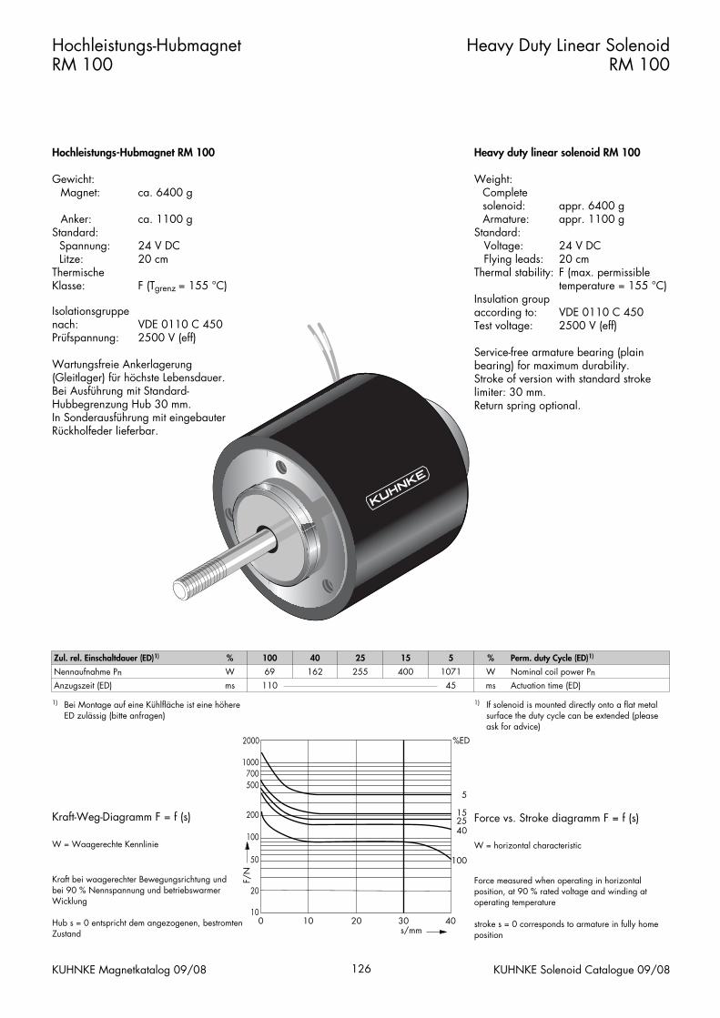
Hochleistungs-Hubmagnet RM 100
Gewicht:Magnet: ca. 6400 g
Anker: ca. 1100 gStandard:
Spannung: 24 V DCLitze: 20 cm
Thermische Klasse: F (Tgrenz = 155 °C)
Isolationsgruppenach: VDE 0110 C 450Prüfspannung: 2500 V (eff)
Wartungsfreie Ankerlagerung (Gleitlager) für höchste Lebensdauer. Bei Ausführung mit Standard-Hubbegrenzung Hub 30 mm. In Sonderausführung mit eingebauterRückholfeder lieferbar.
Kraft-Weg-Diagramm F = f (s)
W = Waagerechte Kennlinie
Kraft bei waagerechter Bewegungsrichtung und bei 90 % Nennspannung und betriebswarmerWicklung
Hub s = 0 entspricht dem angezogenen, bestromtenZustand
Hochleistungs-HubmagnetRM 100
Heavy Duty Linear SolenoidRM 100
Heavy duty linear solenoid RM 100
Weight:Complete solenoid: appr. 6400 gArmature: appr. 1100 g
Standard:Voltage: 24 V DCFlying leads: 20 cm
Thermal stability: F (max. permissibletemperature = 155 °C)
Insulation groupaccording to: VDE 0110 C 450Test voltage: 2500 V (eff)
Service-free armature bearing (plain bearing) for maximum durability. Stroke of version with standard strokelimiter: 30 mm.Return spring optional.
Force vs. Stroke diagramm F = f (s)
W = horizontal characteristic
Force measured when operating in horizontal position, at 90 % rated voltage and winding at operating temperature
stroke s = 0 corresponds to armature in fully homeposition
KUHNKE Magnetkatalog 09/08 126 KUHNKE Solenoid Catalogue 09/08
Zul. rel. Einschaltdauer (ED)1) % 100 40 25 15 5 % Perm. duty Cycle (ED)1)
Nennaufnahme PnAnzugszeit (ED)
Wms
69110
162 255 400 107145
Wms
Nominal coil power PnActuation time (ED)
1) Bei Montage auf eine Kühlfläche ist eine höhereED zulässig (bitte anfragen)
1) If solenoid is mounted directly onto a flat metalsurface the duty cycle can be extended (pleaseask for advice)
0 10 20 30 40s/mm
F/N
10
20
50
2000 %ED
40
100
2515
5
100
200
500700
1000

Hochleistungs-HubmagnetRM 100
Heavy Duty Linear SolenoidRM 100
KUHNKE Magnetkatalog 09/08 127 KUHNKE Solenoid Catalogue 09/08
Ø60
Ø58
M12
M12 M12
110
~23
1212
50+1
956
677
109
1371 65
50+1
19 30
Ø76
Ø10
0
88110
Ø58
M8
Ø11
,5
122
294
M12
Ø60
Ø60Ø58
M12
M12
144
~57
1250
+1
956
665
143
13
156
316
50+1
1419 30
Ø76
Ø10
0
88110
Ø58
M8
Ø11
,5
ohne Hubbegrenzung without stroke limiter
mit Hubbegrenzung with stroke limiter
Hub
richt
ung
Maß
e im
bes
trom
ten
Zusta
nd
Direction of stroke
Dim
ensions given with
armature in fully hom
e positionH
ubric
htun
g M
aße
im b
estro
mte
n Zu
stand
D
irection of strokeD
imensions given w
ith arm
ature in fully home position

Diese Produkte entsprechen der Niederspan-nungsrichtlinie 73/23/EWG. Die Einhaltungder EMV-Richtlinie 89/336/EWG ist mit ent-sprechenden Schaltgeräten bzw-. Ansteue-rungen vom Anwender sicherzustellen.
Dieser Katalog ist vor allem für denKonstrukteur, Projekteur und Geräteentwicklerbestimmt. Er gibt keine Auskunft überLiefermöglichkeiten.Die angegebenen Daten dienen allein derProduktbeschreibung und sind nicht alsgarantierte Beschaffenheit des Produktes imRechtssinne aufzufassen.Beschaffenheitsvereinbarungen bleiben demkonkreten Vertragsverhältnis vorbehalten.Etwaige Schadensersatzansprüche gegen uns– gleich aus welchem Rechtsgrund – sind aus-geschlossen, soweit uns nicht Vorsatz odergrobe Fahrlässigkeit trifft. Vervielfältigungen,auch auszugsweise, dürfen nur mitGenehmigung des Autors vorgenommen werden. Änderungen, Auslassungen undIrrtümer vorbehalten.
These products comply with low voltage regulations 73/23/EWG. The user must ensure that EMC regulation 89/336/EWG iscomplied with using the appropriate switchingdevices or drivers respectively.
This catalogue is primarily intended for thedesign and development engineer. It is not an indication of delivery possibilities.The indicated data only serve the descriptionof the product, they are not to be understoodas the guaranteed quality of the product inlegal terms. Agreements as to the quality of the product arereserved to the proper contractual relationship.Claims of damages against us – on whatevergrounds – are excluded, except in instances ofdeliberate intent or gross negligence on ourpart. Reproduction, even of extracts only withthe author’s approval. We reserve the rights of modification, omission,error.

Weight:Complete solenoid: appr. 75 gArmature: appr. 21 g
Standard:Voltage: 24 V DCFlying leads: 10 cm
Thermal stability: B (max. permissibletemperature = 130 °C)
Insulation groupaccording to: VDE 0110/4 KV/3Test voltage: 2.5 KV (eff)
Service-free armature bearing (plainbearing) for maximum durability.Return spring optional.Solenoids with order specificationHL218-R-... are available with returnspring F (0 mm) = 0.6 N and F (6 mm) = 0.27 N. Observe correct mounting (armatureweight).
Force vs. Stroke diagramm F = f (s)
Force measured when operating in horizontal position, at 90 % rated voltage and with winding at operating temperature
stroke s = 0 corresponds to armature infully home position
Force vs. stroke characzeristics measured withoutreturn spring
Gewicht:Magnet: ca. 75 g
Anker: ca. 21 gStandard:
Spannung: 24 V DCLitze: 10 cm
Thermische Klasse: B (Tgrenz = 130 °C)
Isolationsgruppenach: VDE 0110/4 KV/3Prüfspannung: 2,5 KV (eff)
Wartungsfreie Ankerlagerung (Gleitlager) für höchste Lebensdauer.Auf Wunsch mit eingebauter Rückhol-feder lieferbar. Die Magnete mit der BestellbezeichnungHL218-R-... sind mit einer internenRückholfeder F (0 mm) = 0,6 N und F (6 mm) = 0,27 N ausgeführt. Einbaulage (Ankergewicht) beachten.
Kraft-Weg-Diagramm F = f (s)
Kraft bei waagerechter Bewegungsrichtung undbei 90 % Nennspannung und betriebswarmerWicklung
Hub s = 0 entspricht dem angezogenen,bestromten Zustand
Kraft-Wege-Kennlinien sind ohne Feder gemessen
HubmagnetHL 218
Stoßende und ziehende Ausführung
Linear SolenoidHL 218
Thrust and pull type
KUHNKE Magnetkatalog 09/08 88 KUHNKE Solenoid Catalogue 09/08
Zul. rel. Einschaltdauer (ED)3) % 100 40 20 10 6 % Perm. duty cycle (ED)3)
Nennaufnahme P 20 W 5 13 25 48 77 W Nominal coil power P 20
3) Bei Montage auf eine Kühlfläche ist eine höhere ED zulässig (bitte anfragen)
3) If solenoid is mounted directly onto a flat metal surface the duty cycle can be extended (please ask for advice)
Bestellformel HL 218 – R – – F – 24 V DC 100 % ED Order specifications
HubmagnetBauart
HL218
Linear solenoidDesign type
RückholfederAnschlussart
Litze (Standardlänge 10 cm)Steckkontakt (2,8 x 0,8 DIN 46247; optional)
R
FA
Return springCoil terminals
Flying leads (10 cm standard length)Plug connector (2.8 x 0.8 DIN 46247; optional)
Nennspannung (Standardspannung)1)
Zulässige relative Einschaltdauer bei Luftkühlung (LK)2)
24100 % ED
Nominal voltage (standard voltage)1)
Perm. duty cycle under air cooled conditions (LK)2)
1) Andere Spannung bis max. 220 V DC auf Anfrage.2) Andere ED als 100 % ED auf Anfrage.
1) Other voltages up to max. 220 V DC on request.2) Other ED than 100 % ED on request.
0 1 2 3 4 5 6s/mm
F/N
0,1
0,20,3
0,5
30
10
%ED
40
20
106
100
23
58
1

HubmagnetHL 218
Stoßende und ziehende Ausführung
Linear SolenoidHL 218
Thrust and pull type
KUHNKE Magnetkatalog 09/08 89 KUHNKE Solenoid Catalogue 09/08
20
12+1
M3
10
Ø3
4
8
M3
36
37,5
9
48
25,5
Ø10 3
Ø14 25
21
Maße im bestromten Zustand
–––––––>Hubrichtung
Dimensions given with armature in fullyhome position–––––––>Direction of stroke
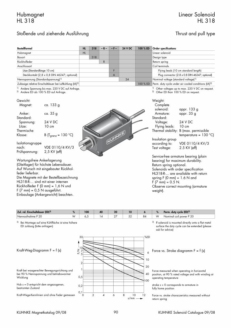
Weight:Complete solenoid: appr. 133 gArmature: appr. 35 g
Standard:Voltage: 24 V DCFlying leads: 10 cm
Thermal stability: B (max. permissibletemperature = 130 °C)
Insulation groupaccording to: VDE 0110/4 KV/3Test voltage: 2.5 KV (eff)
Service-free armature bearing (plain bearing) for maximum durability.Return spring optional.Solenoids with order specificationHL318-R-... are available with returnspring F (0 mm) = 1.6 N and F (7 mm) = 0.5 N. Observe correct mounting (armatureweight).
Force vs. Stroke diagramm F = f (s)
Force measured when operating in horizontal position, at 90 % rated voltage and with winding at operating temperature
stroke s = 0 corresponds to armature infully home position
Force vs. stroke characzeristics measured withoutreturn spring
Gewicht:Magnet: ca. 133 g
Anker: ca. 35 gStandard:
Spannung: 24 V DCLitze: 10 cm
ThermischeKlasse: B (Tgrenz = 130 °C)
Isolationsgruppenach: VDE 0110/4 KV/3Prüfspannung: 2,5 KV (eff)
Wartungsfreie Ankerlagerung (Gleitlager) für höchste Lebensdauer.Auf Wunsch mit eingebauter Rückhol-feder lieferbar. Die Magnete mit der BestellbezeichnungHL318-R-... sind mit einer internenRückholfeder F (0 mm) = 1,6 N und F (7 mm) = 0,5 N ausgeführt. Einbaulage (Ankergewicht) beachten.
Kraft-Weg-Diagramm F = f (s)
Kraft bei waagerechter Bewegungsrichtung undbei 90 % Nennspannung und betriebswarmerWicklung
Hub s = 0 entspricht dem angezogenen,bestromten Zustand
Kraft-Wege-Kennlinien sind ohne Feder gemessen
HubmagnetHL 318
Stoßende und ziehende Ausführung
Linear SolenoidHL 318
Thrust and pull type
KUHNKE Magnetkatalog 09/08 90 KUHNKE Solenoid Catalogue 09/08
Zul. rel. Einschaltdauer (ED)3) % 100 40 20 10 6 % Perm. duty cycle (ED)3)
Nennaufnahme P 20 W 6,5 14 27 52 84 W Nominal coil power P 20
3) Bei Montage auf eine Kühlfläche ist eine höhere ED zulässig (bitte anfragen)
3) If solenoid is mounted directly onto a flat metal surface the duty cycle can be extended (please ask for advice)
Bestellformel HL 318 – R – – F – 24 V DC 100 % ED Order specifications
HubmagnetBauart
HL318
Linear solenoidDesign type
RückholfederAnschlussart
Litze (Standardlänge 10 cm)Steckkontakt (2,8 x 0,8 DIN 46247; optional)
R
FA
Return springCoil terminals
Flying leads (10 cm standard length)Plug connector (2.8 x 0.8 DIN 46247; optional)
Nennspannung (Standardspannung)1)
Zulässige relative Einschaltdauer bei Luftkühlung (LK)2)
24100 % ED
Nominal voltage (standard voltage)1)
Perm. duty cycle under air cooled conditions (LK)2)
1) Andere Spannung bis max. 220 V DC auf Anfrage.2) Andere ED als 100 % ED auf Anfrage.
1) Other voltages up to max. 220 V DC on request.2) Other ED than 100 % ED on request.
0 2 4 6 8 10 12s/mm
F/N
0,1
0,2
0,5
30
10
%ED
40
20
10
6
100
1
2
57

HubmagnetHL 318
Stoßende und ziehende Ausführung
Linear SolenoidHL 318
Thrust and pull type
KUHNKE Magnetkatalog 09/08 91 KUHNKE Solenoid Catalogue 09/08
Ø12 3
Ø17
25,54212
43
57
12
Ø3
12+1
5
24
M3
M3
9
3018
12
24
M3
Maße im bestromten Zustand
–––––––>Hubrichtung
Dimensions given with armature in fullyhome position–––––––>Direction of stroke

Weight:Complete solenoid: appr. 390 gArmature: appr. 90 g
Standard:Voltage: 24 V DCFlying leads: 10 cm
Thermal stability: B (max. permissibletemperature = 130 °C)
Insulation groupaccording to: VDE 0110/4 KV/3Test voltage: 2.5 KV (eff)
Service-free armature bearing (plain bearing) for maximum durability.Return spring optional.Solenoids with order specificationHL618-R-... are available with returnspring F (0 mm) = 2.2 N and F (20 mm) = 0.9 N. Observe correct mounting (armatureweight).
Force vs. Stroke diagramm F = f (s)
Force measured when operating in horizontal position, at 90 % rated voltage and with winding at operating temperature
stroke s = 0 corresponds to armature infully home position
Force vs. stroke characzeristics measured withoutreturn spring
Gewicht:Magnet: ca. 390 g
Anker: ca. 90 gStandard:
Spannung: 24 V DCLitze: 10 cm
Thermische Klasse: B (Tgrenz = 130 °C)
Isolationsgruppenach: VDE 0110/4 KV/3Prüfspannung: 2,5 KV (eff)
Wartungsfreie Ankerlagerung (Gleitlager) für höchste Lebensdauer.Auf Wunsch mit eingebauter Rückhol-feder lieferbar. Die Magnete mit der BestellbezeichnungHL618-R-... sind mit einer internenRückholfeder F (0 mm) = 2,2 N und F (20 mm) = 0,9 N ausgeführt.Einbaulage (Ankergewicht) beachten.
Kraft-Weg-Diagramm F = f (s)
Kraft bei waagerechter Bewegungsrichtung undbei 90 % Nennspannung und betriebswarmerWicklung
Hub s = 0 entspricht dem angezogenen,bestromten Zustand
Kraft-Wege-Kennlinien sind ohne Feder gemessen
HubmagnetHL 618
Stoßende und ziehende Ausführung
Linear SolenoidHL 618
Thrust and pull type
KUHNKE Magnetkatalog 09/08 92 KUHNKE Solenoid Catalogue 09/08
Zul. rel. Einschaltdauer (ED)3) % 100 40 20 10 6 % Perm. duty cycle (ED)3)
Nennaufnahme P 20 W 12 31 50 96 140 W Nominal coil power P 20
3) Bei Montage auf eine Kühlfläche ist eine höhere ED zulässig (bitte anfragen)
3) If solenoid is mounted directly onto a flat metal surface the duty cycle can be extended (please ask for advice)
Bestellformel HL 618 – R – – F – 24 V DC 100 % ED Order specifications
HubmagnetBauart
HL618
Linear solenoidDesign type
RückholfederAnschlussart
Litze (Standardlänge 10 cm)Steckkontakt (6,3 x 0,8 DIN 46247; optional)
R
FA
Return springCoil terminals
Flying leads (10 cm standard length)Plug connector (6.3 x 0.8 DIN 46247; optional)
Nennspannung (Standardspannung)1)
Zulässige relative Einschaltdauer bei Luftkühlung (LK)2)
24100 % ED
Nominal voltage (standard voltage)1)
Perm. duty cycle under air cooled conditions (LK)2)
1) Andere Spannung bis max. 220 V DC auf Anfrage.2) Andere ED als 100 % ED auf Anfrage.
1) Other voltages up to max. 220 V DC on request.2) Other ED than 100 % ED on request.
0 5 10 15 20 s/mm
F/N
0,1
0,2
0,5
100 %ED
100
4020
106
1
2
58
10
2030
50

HubmagnetHL 618
Stoßende und ziehende Ausführung
Linear SolenoidHL 618
Thrust and pull type
KUHNKE Magnetkatalog 09/08 93 KUHNKE Solenoid Catalogue 09/08
Ø18 6
Ø25
30,55016
52
70
M4
4530
20
38
20
12+1
30
M4
Ø4
8 M4
10
± 0,
5
± 0,5
Maße im bestromten Zustand
–––––––>Hubrichtung
Dimensions given with armature in fullyhome position–––––––>Direction of stroke

Diese Produkte entsprechen der Niederspan-nungsrichtlinie 73/23/EWG. Die Einhaltungder EMV-Richtlinie 89/336/EWG ist mit ent-sprechenden Schaltgeräten bzw-. Ansteue-rungen vom Anwender sicherzustellen.
Dieser Katalog ist vor allem für denKonstrukteur, Projekteur und Geräteentwicklerbestimmt. Er gibt keine Auskunft überLiefermöglichkeiten.Die angegebenen Daten dienen allein derProduktbeschreibung und sind nicht alsgarantierte Beschaffenheit des Produktes imRechtssinne aufzufassen.Beschaffenheitsvereinbarungen bleiben demkonkreten Vertragsverhältnis vorbehalten.Etwaige Schadensersatzansprüche gegen uns– gleich aus welchem Rechtsgrund – sind aus-geschlossen, soweit uns nicht Vorsatz odergrobe Fahrlässigkeit trifft. Vervielfältigungen,auch auszugsweise, dürfen nur mitGenehmigung des Autors vorgenommen werden. Änderungen, Auslassungen undIrrtümer vorbehalten.
These products comply with low voltage regulations 73/23/EWG. The user must ensure that EMC regulation 89/336/EWG iscomplied with using the appropriate switchingdevices or drivers respectively.
This catalogue is primarily intended for thedesign and development engineer. It is not an indication of delivery possibilities.The indicated data only serve the descriptionof the product, they are not to be understoodas the guaranteed quality of the product inlegal terms. Agreements as to the quality of the product arereserved to the proper contractual relationship.Claims of damages against us – on whatevergrounds – are excluded, except in instances ofdeliberate intent or gross negligence on ourpart. Reproduction, even of extracts only withthe author’s approval. We reserve the rights of modification, omission,error.