Embed Size (px)
DESCRIPTION
Hughes Modem Guide
Citation preview


Contents
Understanding safety messages..........................................................................................xiAdditional safety symbols.......................................................................................................................xi
Scope and audience............................................................................................................xiiiContact Information...........................................................................................................xv
Chapter 1: Satellite modem overview...........................................................1Supported configurations.........................................................................................................................2Satellite modem specifications.................................................................................................................3Power supply information........................................................................................................................4Modem operating position.......................................................................................................................5Computer requirements............................................................................................................................5
Chapter 2: System Control Center.................................................................7Accessing the System Control Center......................................................................................................8
Creating a shortcut to the System Control Center........................................................................8System Control Center home page...........................................................................................................9
Text links......................................................................................................................................9Common features on System Control Center screens............................................................................10
Button links................................................................................................................................11System Status button......................................................................................................12
Links in left panel.......................................................................................................................13Small icon on System Control Center screens...........................................................................13Status and information screens...................................................................................................13
State codes on status and information screens...............................................................14Red flag indicator...........................................................................................................15
System Status page.................................................................................................................................15Typical values for System Status parameters.............................................................................16Red flags on System Status page................................................................................................18
Reception Information page...................................................................................................................19Typical values for Reception Information parameters...............................................................19Red flags on Reception Information page..................................................................................20
Transmission Information page..............................................................................................................21Typical values for Transmission Information parameters..........................................................22Red flags on Transmission Information page.............................................................................23
Terminal Status page..............................................................................................................................23Typical values for Terminal Status parameters..........................................................................24
System Information page........................................................................................................................26Typical values for System Information parameters....................................................................27
State codes..............................................................................................................................................29
iii

Viewing the state codes list........................................................................................................32Connectivity Test page...........................................................................................................................33
Chapter 3: HughesNet Tools.........................................................................35Launching HughesNet Tools..................................................................................................................36HughesNet Tools home page..................................................................................................................36
I Have a Technical Problem.......................................................................................................36Support Library..........................................................................................................................37Helpful Tools..............................................................................................................................37
Chapter 4: LEDs............................................................................................39Front panel LEDs...................................................................................................................................40LAN port LEDs......................................................................................................................................41
Chapter 5: Troubleshooting..........................................................................43Rescue switch.........................................................................................................................................44Cannot Access the System Control Center.............................................................................................44Testing connectivity to the satellite........................................................................................................44Hot cable connector................................................................................................................................46Checking for viruses and firewall issues................................................................................................47
Appendix A: Computer settings...................................................................49Understanding the modem address and computer address ....................................................................49
If you don't know the modem’s public IP address….................................................................50Configuring a computer to use DHCP...................................................................................................51
Configuring Windows Vista to use DHCP.................................................................................51Configuring Windows XP to use DHCP....................................................................................53Configuring Windows 2000 to use DHCP.................................................................................55Configuring a Mac computer to use DHCP...............................................................................56
Configuring a computer for a public IP address.....................................................................................58Configuring Windows Vista – Public IP address.......................................................................58Configuring Windows XP – Public IP address..........................................................................60Configuring Windows 2000 – Public IP address.......................................................................62Configuring a Mac computer – Public IP address......................................................................64
Configuring proxy settings.....................................................................................................................66Configuring Internet Explorer to not use a proxy server............................................................66Configuring Netscape to not use a proxy server .......................................................................66
Appendix B: Home networking....................................................................69Wireless network basics.........................................................................................................................69Ethernet (wired) network basics ............................................................................................................70
iv
Contents

Appendix C: Conformance with standards and directives........................73Electromagnetic interference (EMI).......................................................................................................73
FCC Part 15................................................................................................................................73Canada Class B warning.............................................................................................................74
Operational and safety requirements for Canada...................................................................................74Repairs in Canada.......................................................................................................................74
Appendix D: Acronyms used in this Guide.................................................75
v
Contents


Table of Figures
Figure 1: HN9000 satellite modem..................................................................................................................................1Figure 2: Single-host configuration..................................................................................................................................2Figure 3: Multiple-host configuration in an Ethernet wired LAN...................................................................................2Figure 4: Private network configuration..........................................................................................................................3Figure 5: Power supply for the HN9000 satellite modem ...............................................................................................4Figure 6: HN9000 in vertical position..............................................................................................................................5Figure 7: Icon for creating shortcut..................................................................................................................................8Figure 8: System Control Center home page...................................................................................................................9Figure 9: Common features on System Control Center screens....................................................................................11Figure 10: System Control Center button links..............................................................................................................11Figure 11: Small icon on System Control Center screens..............................................................................................13Figure 12: Format of status and information screens.....................................................................................................14Figure 13: Example of a state code................................................................................................................................14Figure 14: Red flag problem indicator...........................................................................................................................15Figure 15: System Status page.......................................................................................................................................16Figure 16: Reception Information page..........................................................................................................................19Figure 17: Transmission Information page....................................................................................................................22Figure 18: Terminal Status page (top part).....................................................................................................................26Figure 19: System Information page (top part)..............................................................................................................26Figure 20: Examples of state codes................................................................................................................................29Figure 21: Terminal Connectivity Test page..................................................................................................................33Figure 22: HughesNet Tools home page .......................................................................................................................36Figure 23: Front panel LEDs on the HN9000 modem...................................................................................................40Figure 24: LAN port LEDs............................................................................................................................................41Figure 25: Satellite loopback connectivity test..............................................................................................................45Figure 26: Terminal Connectivity Test page..................................................................................................................45Figure 27: Connectivity Test results page......................................................................................................................46Figure 28: Example of Addressing parameters showing available private IP addresses...............................................49Figure 29: Example of Addressing parameters showing one available public IP address.............................................50Figure 30: Network connections – Windows Vista........................................................................................................51Figure 31: Local Area Connection Properties – Windows Vista....................................................................................52Figure 32: Internet Protocol Properties – Windows Vista..............................................................................................52Figure 33: Network connections – Windows XP...........................................................................................................53Figure 34: Local Area Connection Properties – Windows XP.......................................................................................54Figure 35: Internet Protocol Properties – Windows XP.................................................................................................54Figure 36: Accessing Local Area Connection Properties – Windows 2000..................................................................62Figure 37: Local Area Connection Properties Dialog – Windows 2000........................................................................63Figure 38: Internet Protocol Properties – Windows 2000..............................................................................................63Figure 39: Mac System Preferences menu.....................................................................................................................57Figure 40: Mac Network screen.....................................................................................................................................62Figure 41: Select DHCP from the configure drop-down menu......................................................................................58
vii

Figure 42: Network connections – Windows Vista........................................................................................................59Figure 43: Local Area Connection Properties – Windows Vista....................................................................................59Figure 44: Internet Protocol Properties – Windows Vista..............................................................................................60Figure 45: Accessing Local Area Connection Properties – Windows XP.....................................................................61Figure 46: Local Area Connection Properties Dialog – Windows XP...........................................................................61Figure 47: Internet Protocol Properties – Windows XP.................................................................................................62Figure 48: Accessing Local Area Connection Properties – Windows 2000..................................................................62Figure 49: Local Area Connection Properties Dialog – Windows 2000........................................................................63Figure 50: Internet Protocol Properties – Windows 2000..............................................................................................63Figure 51: Mac System Preferences menu.....................................................................................................................64Figure 52: Mac Network screen.....................................................................................................................................65Figure 53: Select Manually from the configure drop-down menu.................................................................................65Figure 54: LAN settings – Internet Explorer..................................................................................................................66Figure 55: Proxy settings in Netscape Preferences window .........................................................................................67Figure 56: Satellite modem in a wireless home network...............................................................................................70Figure 57: Satellite modem in a wired Ethernet home network ....................................................................................71
viii
Table of Figures

Table of Tables
Table 1: Specifications for the HN9000 satellite modem ................................................................................................3Table 2: Power supply specifications for the HN9000 satellite modem..........................................................................4Table 3: Button links on System Control Center screens...............................................................................................11Table 4: Meaning of System Status button colors..........................................................................................................12Table 5: System Status parameters – typical values and range......................................................................................16Table 6: Explanation of red flags on System Status page..............................................................................................18Table 7: Reception Information parameters – typical values and range........................................................................19Table 8: Explanation of red flags on Reception Information page.................................................................................20Table 9: Transmission Information parameters – typical values and range...................................................................22Table 10: Terminal Status parameters – typical values and range..................................................................................24Table 11: System Information parameters – typical values and range...........................................................................27Table 12: State codes......................................................................................................................................................29Table 13: Front panel LED indications..........................................................................................................................40Table 14: HN9000 standards compliance.......................................................................................................................73
ix


Understanding safety messagesThree types of safety messages are defined according to the severity of the possible hazard each type of message addresses.
This section explains the meaning of the safety alert symbol and specific words that are used in this Guideto bring your attention to safety information.
Safety messages are identified by a label that includes the safety alert symbol and the word DANGER, WARNING, orCAUTION, as shown below. The safety alert symbol alerts you to a potential personal injury hazard. To avoid possibleinjury or death, read and comply with all safety messages that are designated by this symbol.
These words indicate the severity of the potential hazard, as follows:
DANGER indicates a potentially hazardous situation which, if not avoided, will result in death or serious injury.
WARNING indicates a potentially hazardous situation which, if not avoided, could result in death or serious injury.
CAUTION indicates a potentially hazardous situation which, if not avoided, could result in minor or moderate injury.
The NOTICE label is used for advisory messages not related to personal injury. Failure to heed a NOTICE messagecould result in damage to the product or could cause it not to work properly. In some cases failure to heed a NOTICEmessage could result in damage to other property.
A notice is not a safety message but is defined here along with safety messages because notices use a label that lookssimilar to the safety message labels.
Additional safety symbols
In addition to the generic safety alert symbol , other symbols may be used with safety messages to indicatethe type of hazard.
This document uses this symbol to indicate a safety message that concerns a potential electric shock hazard.
xi


Scope and audience
This User Guide describes the features and operation of the Hughes HN9000 satellite modem, which provides Internetaccess by satellite. It also provides certain reference information, such as the meaning of the modem’s front panel LEDs.The HN9000 is designed for consumers and small business users.
This Guide is written for users in the United States and Canada.
xiii


Contact Information
If you experience problems with your Hughes satellite modem, first try the solutions offered in Troubleshooting on page43. If you need assistance, use the contact information listed here.
If you need operational, warranty, or repair support, your contact information will vary depending on where you purchasedyour satellite modem. You may be supported by Hughes Customer Care or another service provider.
For modems purchased from a retail channel or Hughes sales agent
If you purchased this product through a retail channel or Hughes sales agent, you have several support options. Pleasetry these options in the order listed until you find the help you need.
Begin at the HughesNet Customer Care page:
1. Open a web browser on a computer connected to the satellite modem.2. Enter the web address www.myhughesnet.com.3. Click the HughesNet Customer Care link.
The HughesNet Customer Care page opens. Options 1, 2, and 3 below are available on this page:
1. Search our Knowledge Base.
a. In the Self help section, click Knowledge Base Search.b. Follow the on-screen instructions to find the information you need.
2. Email a Customer Care representative.
a. In the Contact Hughes section, click Email.b. Complete the email form.c. Click Email Us!.
3. Chat with a Customer Care representative.
a. In the Contact Hughes section, click Chat.b. Complete the chat form.c. Click Chat with Us!
4. Call a Customer Care representative.
If none of the previous options helped you, call Hughes Customer Care at 1 (866) 347-3292.
For modems purchased from a value-added reseller
If you purchased this product from one of our VARs, do not contact Hughes. Contact your VAR for technical supportaccording to the procedure supplied by them. They are trained to help you with any technical problem.
xv


Chapter
1Satellite modem overview
The HN9000 satellite modem connects to the Internet or an intranet by satelliteand provides Internet or intranet service to a single host, typically a computer,
Topics:
• Supported configurations or to multiple hosts on a LAN. A host may be a computer using Windows orother supported operating system.• Satellite modem specifications
• Power supply information The modem is a self-hosted unit, meaning that it does not depend on a computerto establish and maintain the Internet or intranet connection. However, the• Modem operating positionmodem must be connected to a properly aligned satellite antenna. The modemhas an Ethernet port so it can be connected to a computer or to an Ethernet LAN.
• Computer requirements
Figure 1: HN9000 satellite modem
Note: Acronyms used in this User Guide are identified in Acronyms usedin this Guide on page 75.
After your HN9000 satellite modem has been installed, you can use a webbrowser on your computer to access the Internet or an intranet. You can use alocal area network (LAN) to extend Internet or intranet connectivity to multiplecomputers. This requires a properly configured NIC, an Ethernet cable or wirelessconnection to the LAN, and proper configuration of the computer’s operatingsystem network properties.
The modem has a System Control Center that provides access to systeminformation such as the modem’s IP address and subnet mask. You may needthis information to configure a network. The System Control Center is describedin System Control Center on page 7.
1

Supported configurations
This section shows examples of supported configurations using the HN9000 satellite modem.
The satellite modem may be used in a single-host configuration or multiple-host configuration. In a single-hostconfiguration, the satellite modem is directly connected to the host (a computer), as shown in Figure 2: Single-hostconfiguration on page 2. The Hughes Internet Gateway is a Hughes-operated satellite station that provides a connectionbetween the Internet and the satellite. The gateway routes data to and from the Internet and to and from the satellite,which in turn beams a signal down to the satellite modem to provide Internet connectivity.
Figure 2: Single-host configuration
In a multiple-host configuration, the hosts on the LAN share satellite Internet or intranet connectivity through an Ethernethub, router, or wireless base station. The satellite modem is connected to the hub, router, or wireless base station, asshown in Figure 3: Multiple-host configuration in an Ethernet wired LAN on page 2.
Note: You must provide and configure hub, router, or wireless base station equipment if any of these are used.
Figure 3: Multiple-host configuration in an Ethernet wired LAN
2
Satellite modem overviewHN9000 Satellite Modem User Guide –1037577-0001 Rev. B
Chapter 1

Figure 4: Private network configuration on page 3 shows a private network using two satellite modems at two locations.The thick broken line shows how the network connects a PC at one location and to a PC at a second location. Thisconfiguration requires two antennas—one at each location. The Hughes Internet Gateway connection is optional and isbased upon the network design for the customer private network. Typically this type of configuration is used only inenterprise (business) environments.
Figure 4: Private network configuration
Satellite modem specifications
Table 1: Specifications for the HN9000 satellite modem
1.6 lb (0.73 kg)Weight
2.4 inch (6.1 cm)Width
7.8 inch (19.8 cm)Height
9.0 inch (22.9 cm)Depth
5 to 40º C (Above 5000 ft altitude, the maximumtemperature is reduced by 1º C per 1000 ft.)
Safe operating temperature range
5% to 95% non-condensingSafe operating humidity range
Up to 10,000 ftSafe altitude
ConvectionCooling method
3
Chapter 1HN9000 Satellite Modem User Guide –1037577-0001 Rev. B
Satellite modem overview
TCP/IP (Transmission Control Protocol / Internet Protocol)protocol suite
Protocol support
One Ethernet port supporting 10BaseT or 100BaseToperation, RJ-45-switched
Interface ports
See Power supply information on page 4.Power supplies and power requirements
Power supply information
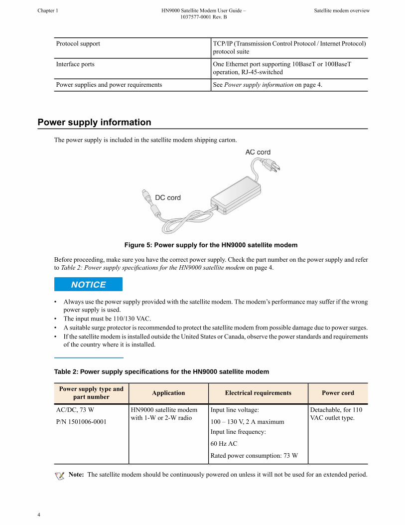
The power supply is included in the satellite modem shipping carton.
Figure 5: Power supply for the HN9000 satellite modem
Before proceeding, make sure you have the correct power supply. Check the part number on the power supply and referto Table 2: Power supply specifications for the HN9000 satellite modem on page 4.
• Always use the power supply provided with the satellite modem. The modem’s performance may suffer if the wrongpower supply is used.
• The input must be 110/130 VAC.• A suitable surge protector is recommended to protect the satellite modem from possible damage due to power surges.• If the satellite modem is installed outside the United States or Canada, observe the power standards and requirements
of the country where it is installed.
Table 2: Power supply specifications for the HN9000 satellite modem
Power cordElectrical requirementsApplicationPower supply type andpart number
Detachable, for 110VAC outlet type.
Input line voltage:
100 – 130 V, 2 A maximum
HN9000 satellite modemwith 1-W or 2-W radio
AC/DC, 73 W
P/N 1501006-0001Input line frequency:
60 Hz AC
Rated power consumption: 73 W
Note: The satellite modem should be continuously powered on unless it will not be used for an extended period.
4
Satellite modem overviewHN9000 Satellite Modem User Guide –1037577-0001 Rev. B
Chapter 1

If there is any reason to remove power from the satellite modem, always unplug the AC power cord from the powersource (power outlet, power strip, or surge protector). Do not remove the DC power cord from the modem’s rear panel.Doing so could result in an electrical shock or damage the modem.
When you re-apply power to the modem, plug the AC power cord into the power source.
Modem operating position
Operate the HN9000 modem only in a vertical position, that is, resting on its built-in base as shown in Figure 6: HN9000in vertical position on page 5. In any other position, the modem may overheat and malfunction because of inadequateventilation.
Figure 6: HN9000 in vertical position
To avoid overheating, operate the HN9000 modem only in the upright vertical position as shown in Figure 6: HN9000in vertical position on page 5.
Computer requirements
The computer that connects to the satellite modem must meet the following minimum requirements. Requirements arelisted by operating system.
All requirements are minimum requirements except those identified as recommended.
The satellite modem may work with a computer that does not meet these requirements, but Hughes supports onlycomputers that meet these requirements. When your HughesNet service was activated, the activation software automatically
5
Chapter 1HN9000 Satellite Modem User Guide –1037577-0001 Rev. B
Satellite modem overview

checked your computer to make sure it meets the minimum requirements. If it did not meet all requirements, but nearlydid, you may have been given a choice to proceed with service activation anyway.
Microsoft Windows Vista Home Basic
• Processor speed: 800 MHz• System memory: 512 MB• Free hard disk space: 150 MB
Microsoft Windows Vista Home Premium, Business, Enterprise, or Ultimate
• Processor speed: 1 GHz• System memory: 1 GB• Free hard disk space: 150 MB
Microsoft Windows XP, Professional or Home Edition
• Processor speed: 233 MHz. Recommended: 300 MHz or higher• System memory: 128 MB. Recommended: 256 MB or more• Free hard disk space: 150 MB
Microsoft Windows 2000, Professional Edition with Service Pack 4
• Processor speed: 133 MHz• System memory: 128 MB• Free hard disk space: 150 MB
Apple Mac 9.0-10.5 (excludes 10.0)
• Processor speed: 300 MHz• System memory: 128 MB• Free hard disk space: 150 MB
Networking requirements
• Ethernet port• Ethernet cable (provided)• Ethernet NIC, 10/100 Mbps, configured as follows:
• Auto-negotiate• DHCP enabled• Obtain an IP address automatically
Note: The computer can be configured to use a public IP address if the HughesNet service plan provides forone or more public IP addresses.
Internet browser
• Internet Explorer 6 or greater, Netscape Navigator, Mozilla Firefox, Safari (for Windows and Mac)• Browser settings:
• HTTP 1.1 or greater enabled• Proxy settings disabled
6
Satellite modem overviewHN9000 Satellite Modem User Guide –1037577-0001 Rev. B
Chapter 1

Chapter
2System Control Center
The System Control Center is a set of screens and links you can use to monitoryour broadband service and troubleshoot the satellite modem in the event of a
Topics:
• Accessing the System ControlCenter
problem. The System Control Center provides access to system status,configuration information, and online documentation through a web browseron the computer that is connected to the satellite modem. Use the System Control• System Control Center home
page Center to find system information for configuring networks or to check systemperformance if the satellite modem does not seem to be functioning properly.• Common features on System
Control Center screens• System Status page• Reception Information page• Transmission Information page• Terminal Status page• System Information page• State codes• Connectivity Test page
7

Accessing the System Control Center
To open the System Control Center on a web browser installed on a computer that is connected to the satellite modem,double-click the System Control Center shortcut on your computer desktop, or follow these steps:
1. Open a web browser such as Internet Explorer or Netscape.2. In the browser address bar, type www.systemcontrolcenter.com or 192.168.0.1 and press Enter.
Note: To use 192.168.0.1, the satellite modem must be configured for a private address, and DHCP must beenabled on the computer.
The System Control Center home page appears as shown in Figure 8: System Control Center home page on page9.
If you are unable to access the System Control Center, refer to Cannot Access the System Control Center on page44.
Creating a shortcut to the System Control CenterYou can create a Windows shortcut on your computer desktop for easy access to the System Control Center home page.
Note: As part of the installation process, the person who installed your satellite modem creates a shortcut to theSystem Control Center, so there should already be a shortcut on your desktop—unless it has been deleted.
1. Open a web browser.
Note: The method described here works for Internet Explorer and Netscape Navigator. It may work with otherbrowsers.
2. Type www.systemcontrolcenter.com or 192.168.0.1 in the browser address bar and press Enter.
Note: To use 192.168.0.1, the satellite modem must be configured for a private IP address, and DHCP mustbe enabled on the computer.
The System Control Center home page appears.
3. Drag the icon that appears in front of the address displayed in the browser to the computer desktop.
Figure 7: Icon for creating shortcut
8
System Control CenterHN9000 Satellite Modem User Guide –1037577-0001 Rev. B
Chapter 2

System Control Center home page
The System Control Center home page contains numerous links to satellite modem features and important informationregarding the operation of the satellite modem.
The button links at the top of the page appear on all System Control Center screens and are explained in Button links onpage 11.
Figure 8: System Control Center home page
Note: On some screens and in some messages you may see the word terminal. This word refers to the satellitemodem.
Text linksThe System Control Center home page includes the following text links:
System Status links
• View System Status – Opens the System Status page, which displays general system status information such assignal strength and administrative status.
• ViewReception Information – Opens the Reception Information page, which displays information on data receivedby the satellite modem.
• View Transmission Information – Opens the Transmission Information page, which displays information on datatransmitted by the satellite modem.
• View Terminal Status – Opens the Terminal Status page, which displays detailed information about the operationalstatus of the satellite modem such as interface packet counts and acceleration statistics.
9
Chapter 2HN9000 Satellite Modem User Guide –1037577-0001 Rev. B
System Control Center

• View System Information – Opens the System Information page, which displays information such as modemidentification information and IP address information.
Note: These links take you to the same destinations as the button links at the top of each System Control Centerpage.
Diagnostic utilities link
Connectivity Test – Opens the Connectivity Test page, which can be used to test the connection between the satellitemodem and the satellite. If you can access the satellite, there is no problem with your physical site connectivity betweenthe modem (inside) and the radio assembly and antenna (outside). See Connectivity Test page on page 33.
Help link
ViewHelp Topics – Opens the Help page, which includes a variety of topics such as recommended browser and TCP/IPsettings.
Restart HN9000 restarts the satellite modem.
myHughesNet
Go to myHughesNet provides access to the HughesNet Web Portal, which contains a variety of useful tools, resources,and information. Access to the HughesNet portal is determined by your specific service plan.
From the HughesNet portal you can click the HughesNet Customer Care link to access a wide variety of supportresources. For example, you can check online usage, test satellite speed, find troubleshooting scripts, manage passwords,access email, check your account and service plan information, and more. The specific portal information and availablefeatures are determined by your specific service plan.
Common features on System Control Center screens
Certain features are common to some or all of the System Control Center screens, as shown in Figure 9: Commonfeatures on System Control Center screens on page 11. These features and other common features are explained in thefollowing sections.
10
System Control CenterHN9000 Satellite Modem User Guide –1037577-0001 Rev. B
Chapter 2
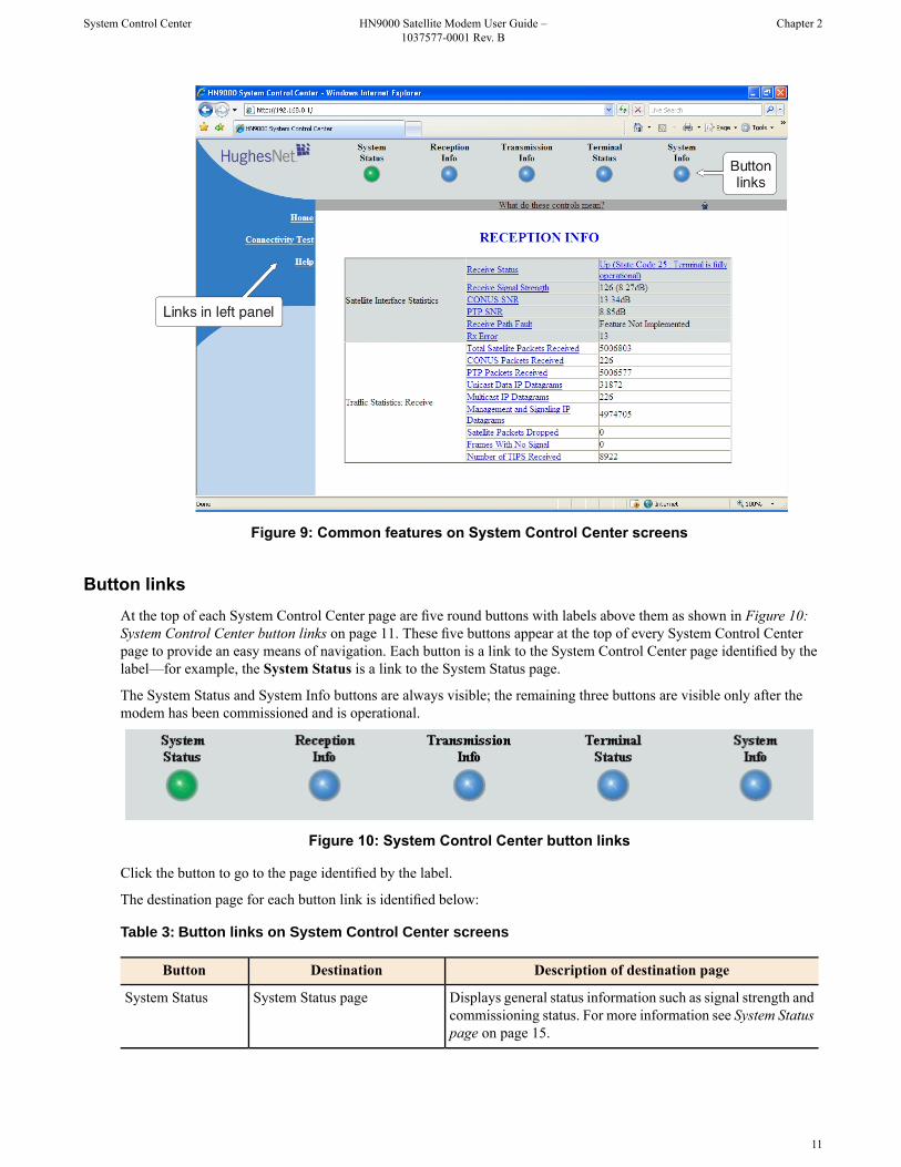
Figure 9: Common features on System Control Center screens
Button linksAt the top of each System Control Center page are five round buttons with labels above them as shown in Figure 10:System Control Center button links on page 11. These five buttons appear at the top of every System Control Centerpage to provide an easy means of navigation. Each button is a link to the System Control Center page identified by thelabel—for example, the System Status is a link to the System Status page.
The System Status and System Info buttons are always visible; the remaining three buttons are visible only after themodem has been commissioned and is operational.
Figure 10: System Control Center button links
Click the button to go to the page identified by the label.
The destination page for each button link is identified below:
Table 3: Button links on System Control Center screens
Description of destination pageDestinationButton
Displays general status information such as signal strength andcommissioning status. For more information see System Statuspage on page 15.
System Status pageSystem Status
11
Chapter 2HN9000 Satellite Modem User Guide –1037577-0001 Rev. B
System Control Center

Description of destination pageDestinationButton
Displays statistics about received data and receive connectionstatus. For more information see Reception Information pageon page 19.
Reception Information pageReception Info
Displays statistics about the transmitted data and transmitconnection status. For more information see TransmissionInformation page on page 21.
Transmission Information pageTransmission Info
Displays detailed information about the operational status ofthe satellite modem. For more information see Terminal Statuspage on page 23.
Terminal Status pageTerminal Status
Displays system information such as ST Name (assigned nameof the satellite modem name) and operational software version.
System Information pageSystem Info
For more information see System Information page on page26.
System Status button
The System Status button (only) is a status indicator as well as a link. It changes color to indicate the satellite modem’scurrent status, as explained in Table 4: Meaning of System Status button colors on page 12. To see more detailed statusinformation, click the System Status button to open the System Status page.
Table 4: Meaning of System Status button colors
MeaningButton color
OK – The satellite modem is operating normally.
Green
Degraded – Degraded means performance is degraded for any of the following reasons:
Yellow
• The Web Acceleration not functioning or in progress. Web Acceleration may betemporarily inactive while you are browsing on a secure HTTP site (https).
• The modem is in fallback mode.• A number of transmissions beyond a certain threshold have not been received by
the satellite (state code 30). This could be caused by weather conditions.
FAP threshold exceeded – The satellite modem has exceeded the FAP threshold specifiedin the HughesNet service plan. Subscribers who exceed the threshold experience reduceddownload speeds for approximately 24 hr.Orange
Problem detected – There is a problem with satellite transmit or receive connectivityor both.Red
If the System Status button is red or yellow , you can look for a red flag next to any value or values on the SystemControl Center information pages (those with tables listing parameters and values). The red flag indicates a problemrelated to the parameter listed next to the flagged value. Click the parameter name to see a pop-up window that mayinclude helpful information, depending on what the problem is.
12
System Control CenterHN9000 Satellite Modem User Guide –1037577-0001 Rev. B
Chapter 2

Links in left panelThe following links appear in the left panel of each System Control Center page (except the home page):
• Home – Opens the System Control Center home page.• Connectivity Test – Opens the Connectivity Test page, which allows you to test the connection between the modem
and the satellite. See Connectivity Test page on page 33.• Help – Opens the Help page. Refer to the Help page, which includes a variety of topics such as getting started and
recommended browser settings.
Small icon on System Control Center screens
The System Control Center screens include a small icon as indicated by the arrow in Figure 11: Small icon on SystemControl Center screens on page 13.
Figure 11: Small icon on System Control Center screens
Do not click this icon unless you are a qualified technician or unless a Hughes Customer Care representative instructsyou to. You could cause the modem to become inoperable.
Status and information screensFive of the System Control Center screens list status and operational parameters and their current values in a tabularformat. For example, the following illustration shows the Transmission Information page. The left column identifies theparameter category, the middle column lists the parameters, and the right column shows the current value of the parameterlisted in the middle column. Parameters are listed in this format on all five status and information screens, which arelisted below:
• System Status page• Reception Information page• Transmission Information page• Terminal Status page• System Information page
13
Chapter 2HN9000 Satellite Modem User Guide –1037577-0001 Rev. B
System Control Center
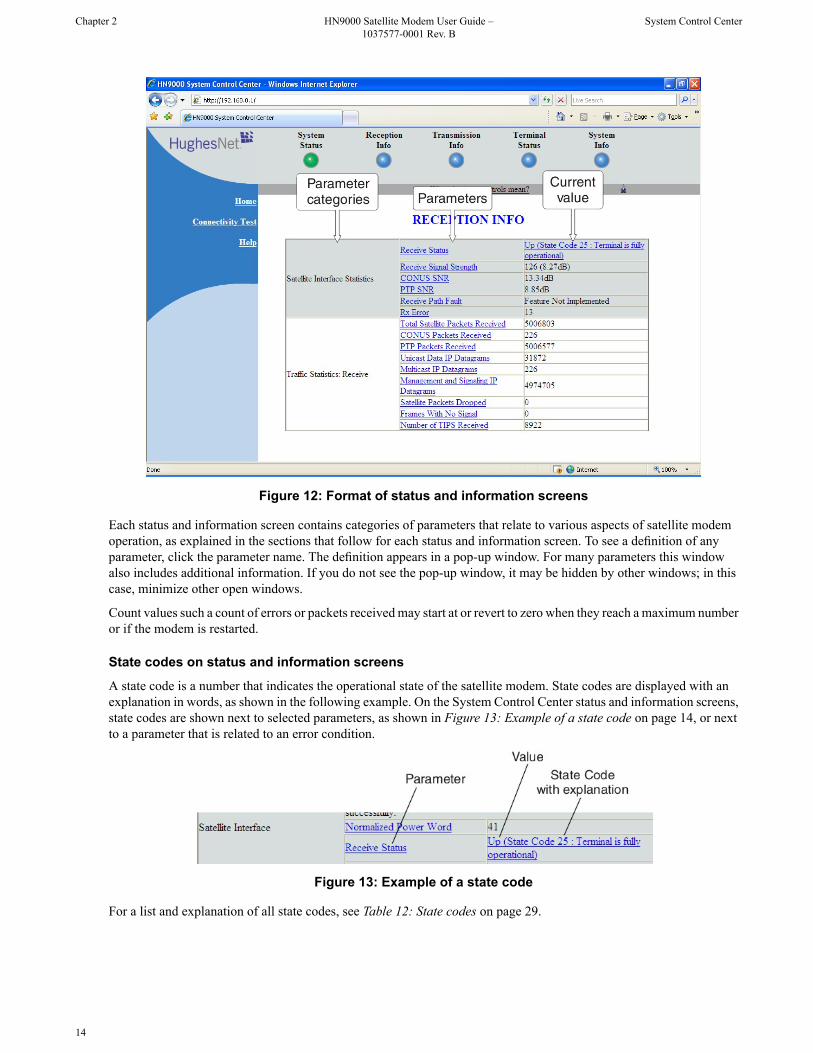
Figure 12: Format of status and information screens
Each status and information screen contains categories of parameters that relate to various aspects of satellite modemoperation, as explained in the sections that follow for each status and information screen. To see a definition of anyparameter, click the parameter name. The definition appears in a pop-up window. For many parameters this windowalso includes additional information. If you do not see the pop-up window, it may be hidden by other windows; in thiscase, minimize other open windows.
Count values such a count of errors or packets received may start at or revert to zero when they reach a maximum numberor if the modem is restarted.
State codes on status and information screens
A state code is a number that indicates the operational state of the satellite modem. State codes are displayed with anexplanation in words, as shown in the following example. On the System Control Center status and information screens,state codes are shown next to selected parameters, as shown in Figure 13: Example of a state code on page 14, or nextto a parameter that is related to an error condition.
Figure 13: Example of a state code
For a list and explanation of all state codes, see Table 12: State codes on page 29.
14
System Control CenterHN9000 Satellite Modem User Guide –1037577-0001 Rev. B
Chapter 2

Red flag indicator
On the status and information screens, a red flag next to a value indicates a problem related to the parameter listed inthe same row where the flagged value appears. The flagged value appears in the right column; the parameter appears inthe middle column. The value indicates the current state of the parameter.
Figure 14: Red flag problem indicator
The red flag may help you or a Hughes Customer Care representative identify and troubleshoot a problem.
If you see a red flag, click the parameter name. The pop-up window that appears may include troubleshooting information.For detailed troubleshooting information concerning red flag indicators, see:
• Red flags on System Status page on page 18• Red flags on Reception Information page on page 20• Red flags on Transmission Information page on page 23
In these three sections you can find the probable cause and possible solution for a red flag next to a specific parameter.
System Status page
The System Status page displays important information about the satellite modem’s operational status.
Available system status values may vary, depending on how the satellite modem is configured. Therefore, some optionsshown in Figure 15: System Status page on page 16 may not appear on your System Status screen.
The System Status page and other System Control Center pages show information that may be particularly useful foradvanced users and for troubleshooting.
15
Chapter 2HN9000 Satellite Modem User Guide –1037577-0001 Rev. B
System Control Center

Figure 15: System Status page
The operational parameters listed on the System Status page are shown in a tabular format. The first (left) columnidentifies the parameter categories:
• Satellite Interface – Contains information on the receive status and signal strength, as well as error messages relatedto satellite modem receive information.
• Administrative States – Contains information on software downloads to this satellite modem, security keys, andother administrative functions.
Typical values for System Status parametersThe following table lists typical values and the range of values for parameters on the System Status page. This informationmay help you understand the values displayed by your satellite modem.
To see the definition of any parameter, click the parameter name on the screen.
Table 5: System Status parameters – typical values and range
Range of valuesTypical valuesParameter
Satellite Interface (parameter category)
0–255160–220Receive Signal Strength
20–6529–45Normalized Power Word
Up – The modem is receiving signalsfrom the satellite.
UpReceive Status
Down – The modem is not receivingsignals from the satellite.
16
System Control CenterHN9000 Satellite Modem User Guide –1037577-0001 Rev. B
Chapter 2
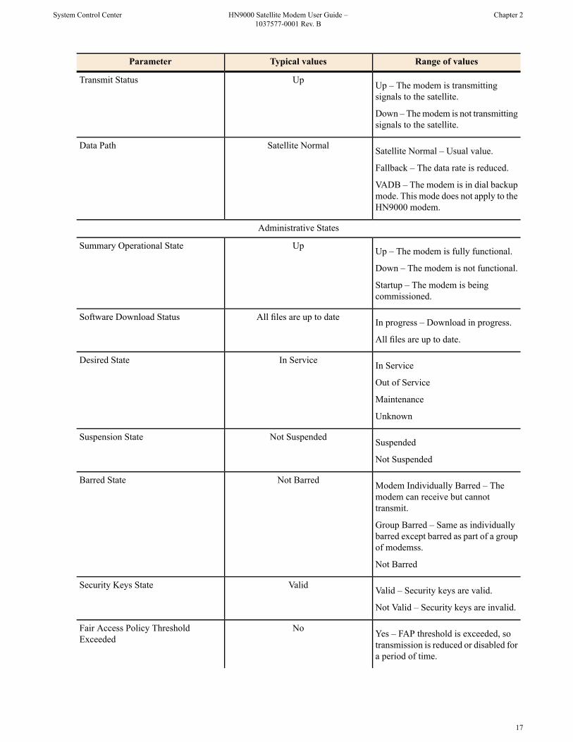
Range of valuesTypical valuesParameter
Up – The modem is transmittingsignals to the satellite.
UpTransmit Status
Down – The modem is not transmittingsignals to the satellite.
Satellite Normal – Usual value.Satellite NormalData Path
Fallback – The data rate is reduced.
VADB – The modem is in dial backupmode. This mode does not apply to theHN9000 modem.
Administrative States
Up – The modem is fully functional.UpSummary Operational State
Down – The modem is not functional.
Startup – The modem is beingcommissioned.
In progress – Download in progress.All files are up to dateSoftware Download Status
All files are up to date.
In ServiceIn ServiceDesired State
Out of Service
Maintenance
Unknown
SuspendedNot SuspendedSuspension State
Not Suspended
Modem Individually Barred – Themodem can receive but cannottransmit.
Not BarredBarred State
Group Barred – Same as individuallybarred except barred as part of a groupof modemss.
Not Barred
Valid – Security keys are valid.ValidSecurity Keys State
Not Valid – Security keys are invalid.
Yes – FAP threshold is exceeded, sotransmission is reduced or disabled fora period of time.
NoFair Access Policy ThresholdExceeded
17
Chapter 2HN9000 Satellite Modem User Guide –1037577-0001 Rev. B
System Control Center

Range of valuesTypical valuesParameter
No – FAP threshold has not beenexceeded.
Red flags on System Status pageA red flag next to a value on the System Status page indicates a problem related to the parameter listed in the same rowwhere the flagged value appears. For explanation, find the flagged parameter in this table. If a state code is displayednext to the parameter, refer to State codes on page 29 to identify the probable cause and possible solution.
Table 6: Explanation of red flags on System Status page
Possible solutionsProbable causeFlagged parameter
See Table 12: State codes on page 29.Various causes are indicated by statecodes 26-35.Receive Status (or)
Transmit StatusThere is a problem with the configuredlatitude and longitude. This problem
Probing failure (occurs only duringcommissioning).
must be corrected by a qualifiedinstaller.
This problem must be corrected by aqualified installer.
Registration failure (occurs only duringcommissioning).
VADB does not apply to the HN9000modem.
VADB – System is in VADB mode.The Satellite link is down and themodem is using the dialup backup link.
Data Path
Wait for weather to improve.Fallback – System is in fallback mode.The modem is experiencing severeweather conditions affecting the datarate. The data rate has been reduced toimprove the transmission.
Look for red flags next to otherparameters.
Modem is not fully operational.Operational State
Look for red flags next to otherparameters.
Modem is in an unknown state.Desired State
Call your service provider.Modem is out of service.
Call your service provider.Modem is under maintenance.
Call your service provider.Modem is suspended by the NOCC.Suspension State
Call your service provider.Modem has been barred individuallyor as part of a group by the NOCC.
Barred State
Wait to see if the flag goes away. If itdoes not, call your service provider.
Modem has not acquired security keys.Security Keys
Wait for normal operation to resume.The modem has greatly exceeded theFAP threshold, and so the modem’s
FAP Status
data rate is reduced for a period oftime.
18
System Control CenterHN9000 Satellite Modem User Guide –1037577-0001 Rev. B
Chapter 2

Reception Information page
The Reception Information page shown in Figure 16: Reception Information page on page 19 displays informationabout data received by the satellite modem.
Figure 16: Reception Information page
The operational parameters listed on the Reception Information page are shown in a tabular format. The first (left)column identifies the parameter categories:
• Satellite Interface Statistics – Contains information on the receive status and signal strength, as well as error messagesrelated to satellite modem receive information.
• Traffic Statistics: Receive – Contains statistical information on data received from the satellite including number ofpackets received or dropped, etc.
Typical values for Reception Information parametersThe following table lists typical values and the range of values for parameters on the Reception Information page. Thisinformation may help you understand the values displayed by your satellite modem.
To see the definition of any parameter, click the parameter name on the screen.
Table 7: Reception Information parameters – typical values and range
Range of valuesTypical valuesParameter
Satellite Interface Statistics (parameter category)
19
Chapter 2HN9000 Satellite Modem User Guide –1037577-0001 Rev. B
System Control Center

Range of valuesTypical valuesParameter
Up – The modem is receiving signalsfrom the satellite.
UpReceive Status
Down – The modem is not receivingsignals from the satellite.
0–255.160–220Receive Signal Strength
4.5–18.0.16CONUS SNR
4.5–18.0.14PTP SNR
Not applicable (parameter reserved forfuture use).
OKReceive Path Fault
Any whole number.≥ 0RX Error
Traffic Statistics: Receive
Any whole number.≥ 0Total Satellite Packets Received
Any whole number.≥ 0CONUS Packets Received
Any whole number.≥ 0PTP Packets Received
Any whole number.≥ 0Unicast Data IP Datagrams
Any whole number.≥ 0Multicast IP Datagrams
Any whole number.≥ 0Management and Signaling IPDatagrams
Any whole number.≥ 0Satellite Packets Dropped
Any whole number.≥ 0Frames With No Signal
Any whole number.≥ 0Number of TIPS Received
Red flags on Reception Information pageA red flag next to a value on the Reception Information page indicates a problem related to the parameter listed in thesame row where the flagged value appears. For explanation, find the flagged parameter in this table. If a state code isdisplayed next to the parameter, refer to Table 12: State codes on page 29 identify the probable cause and possiblesolution.
Table 8: Explanation of red flags on Reception Information page
Possible solutionsProbable causeFlagged parameter
See Table 12: State codes on page 29.Most of these problems must becorrected by a qualified installer.
Various causes are indicated by statecodes 26–35.
Receive Status
There is a problem with the configuredlatitude and longitude. Make sure the
Probing failure (occurs only duringcommissioning).
entered latitude and longitude valuesare correct and in the correct format.This problem must be corrected by aqualified installer.
20
System Control CenterHN9000 Satellite Modem User Guide –1037577-0001 Rev. B
Chapter 2

Possible solutionsProbable causeFlagged parameter
The problem must be corrected by aqualified installer.
Registration failure (occurs only duringcommissioning).
Make sure the receive cable connectedto the modem’s rear panel is tightly
No Beacon (or)
SQF of 0 or 1.
Receive Signal Strength
connected. Any other cableconnections must be checked by aqualified installer.
If all cable connections are tight, theantenna may need to be repointed by aqualified installer.
Wait. When the weather clears, thesignal strength should return to normal.
Weather interference – occurs if rain,snow, or wind is heavy enough tointerfere with signal reception.
Make sure the receive cable connectedto the modem’s rear panel is tightly
Receive IFL cable is loose, faulty, orhas been disconnected.
connected. Any other cableconnections must be checked by aqualified installer.
Antenna pointing by a qualifiedinstaller is required.
Antenna has been severely deflected.
In most cases this problem must becorrected by a qualified installer or
Foreign object is blocking the antenna
other professional (for example, a treespecialist).
Make sure you are using the correctpower supply. (See Power supply
Wrong power supply
information on page 4.) If none ofthe solutions listed here corrects theproblem, contact your service provider.
Wait for the weather to improve. IfPTP SNR is flagged and you
Average SNR is too low. Severeweather condition.
PTP SNR
experience service problems but theweather is good, contact your serviceprovider.
Transmission Information page
The Transmission Information page shown in Figure 17: Transmission Information page on page 22 displays informationabout data transmissions from the satellite satellite modem. The information on this screen may be useful to a HughesCustomer Care representative if you need help in resolving a problem.
21
Chapter 2HN9000 Satellite Modem User Guide –1037577-0001 Rev. B
System Control Center

Figure 17: Transmission Information page
The operational parameters listed on the Transmission Information page are shown in a tabular format. The first (left)column identifies the parameter categories:
• Satellite Interface Statistics – Contains information on transmit status and signal strength, as well astransmission-related error messages.
• Traffic Statistics: Transmit – Contains statistical information on the specific data transmitted to the satellite fromthis satellite satellite modem.
Typical values for Transmission Information parametersThe following table lists typical values and the range of values for parameters on the Transmission Information page.This information may help you understand the values displayed by your satellite modem.
To see the definition of any parameter, click the parameter name on the screen.
Table 9:Transmission Information parameters – typical values and range
Range of valuesTypical valuesParameter
Satellite Interface Statistics (parameter category)
Up – The modem is transmittingsignals to the satellite.
UpTransmit Status
Down – The modem is not transmittingsignals to the satellite.
Any whole number.≥ 0Tx Error
Not applicable (parameter reserved forfuture use).
OKTransmit Path Fault
Traffic Statistics: Transmit
22
System Control CenterHN9000 Satellite Modem User Guide –1037577-0001 Rev. B
Chapter 2

Range of valuesTypical valuesParameter
Any whole number.≥ 0Total Satellite Packets Transmitted
Any whole number.≥ 0Total Satellite Packets Dropped
Red flags on Transmission Information pageIf you see a red flag next to Transmit Status on the Transmission Information page, see Transmit Status in Table 6:Explanation of red flags on System Status page on page 18. The information for Transmit Status in that table also appliesto the Transmission Information page.
Terminal Status page
The Terminal Status page displays information about the operational state of the satellite modem and operational statisticssuch as messages and packets sent, received, and dropped. It indicates whether acceleration is enabled and provides acount of traffic that moves across the LAN to the satellite modem.
Figure 18: Terminal Status page (top part)
The operational parameters listed on the Terminal Status page are shown in a tabular format. The first (left) columnidentifies the parameter categories:
• Overall Status – Shows the major features such as dial backup or acceleration (not all features may be part of yourservice plan.
• Transport Interface Receive Statistics – Indicates messages received and decoded by the satellite modem from thesatellite.
23
Chapter 2HN9000 Satellite Modem User Guide –1037577-0001 Rev. B
System Control Center

• Transport Interface Transmit Statistics – Indicates messages being queued up by the satellite modem for transmissionto the satellite.
• LAN Interface Statistics – Shows traffic across the LAN interface to the satellite modem.• IP Forwarding and Routing Statistics – These refer to system control messages.• Local IP Interface Statistics – Sum of various counts of messages.• Dial Backup Status – Count of dial backup traffic if the feature is enabled. (Some listed features may not be included
in your service plan.)• TCP Acceleration Statistics – Counts of messages and connections used between the satellite modem and its destination
if the feature is enabled. (Some listed features may not be included in your service plan.)• SSL Acceleration Statistics – Counts of SSL traffic if the feature is enabled. (Some listed features may not be included
in your service plan.)• DNS Caching Statistics – Counts on local storage of data if the feature is enabled. (Some listed features may not be
included in your service plan.)• Management Statistics – Various internal network management traffic counts.• Turbo Page Statistics – Counts of various web page requests and objects if the feature is enabled. (Some listed features
may not be included in your service plan.)
Typical values for Terminal Status parametersThe following table lists typical values and the range of values for parameters on the Terminal Status page. Thisinformation may help you understand the values displayed by your satellite modem.
To see the definition of any parameter, click the parameter name on the screen.
The Dial Backup Status parameter and Dial Backup Status category of parameters do not apply to the HN9000 satellitemodem.
Table 10:Terminal Status parameters – typical values and range
Range of valuesTypical valuesParameter
Overall Status (parameter category)
UpUpLAN Interface Status
Down
Out of Service
Maintenance
Unknown
DisabledDisabledDial Backup Status
Connected
Connecting: ...
Disconnecting: ...
Disconnected: ...
EnabledEnabledTCP Acceleration Status
Disabled
EnabledEnabledTurbo Page Status
24
System Control CenterHN9000 Satellite Modem User Guide –1037577-0001 Rev. B
Chapter 2

Range of valuesTypical valuesParameter
Disabled
DisabledDisabledSSL Acceleration Status
Connected to Server
Connecting to Server
Disconnected from Server
EnabledEnabledDNS Acceleration Status
Disabled
Transport Interface Receive Statistics
Any whole number≥ 0Data Messages Received
Any whole number≥ 0Messages Dropped: Protocol Error
Transport Interface Transmit Statistics
Any whole number≥ 0Data Messages Sent
Any whole number≥ 0Data Messages Dropped: ProtocolError
LAN Interface Statistics
Any whole number≥ 0Unicast Messages Received
Any whole number≥ 0Multicast Messages Received
Any whole number≥ 0IP Fragments Received
Any whole number≥ 0Ethernet Input Errors
Any whole number≥ 0Unicast Messages Sent
Any whole number≥ 0Multicast Messages Sent
Any whole number≥ 0Ethernet Output Errors
IP Forwarding and Routing Statistics
Any whole number≥ 0IP Packets Dropped : ForwardingErrors
Any whole number≥ 0ICMP Redirects Sent
Any whole number≥ 0ISRP Redirects Sent
Any whole number≥ 0Current Number of Static Routes
Any whole number≥ 0Current Number of RIP Routes
Any whole number≥ 0Current Number of Redirect Routes
Any whole number≥ 0Current Number of ISRP Routes
Local IP Interface Statistics
Any whole number≥ 0IP Packets Received
Any whole number≥ 0IP Packets Sent
25
Chapter 2HN9000 Satellite Modem User Guide –1037577-0001 Rev. B
System Control Center

Range of valuesTypical valuesParameter
Dial Backup Status
Any whole number≥ 0Data Packets Received
System Information page
The System Information page shown in Figure 18: Terminal Status page (top part) on page 26 provides systeminformation for the satellite modem such as ST name (modem name), Site ID (Site Id), and operational software version.
Figure 19: System Information page (top part)
Note: Print the System Information page and save it. Click Print this page next to the printer icon. If you experiencea problem with your satellite modem this page may not be accessible. Information on this screen may be useful toa Hughes Customer Care representative in helping you to resolve the problem.
The operational parameters listed on the System Information page are shown in a tabular format. The first (left) columnidentifies the parameter categories:
• Identification – Contains system ID information such as Site ID (installation site ID) and ST name (a unique namethat identifies the satellite modem).
• Software – Contains version information on the various software applications resident on the satellite modem suchas commissioning and operational software. (Commissioning refers to initial start-up of the modem.)
• Satellite – Contains information pertaining to communication with the satellite such as antenna size, transmit radiowattage, and uplink transmission mode.
• Addressing – Contains addressing information such as LAN port address and subnet mask and available public IPaddresses (if any, depending on your service plan).
26
System Control CenterHN9000 Satellite Modem User Guide –1037577-0001 Rev. B
Chapter 2

• Software Features – This section lists the optional features and provides information on whether they are currentlyactive. These features are enabled or disabled per your service plan and cannot be changed locally.
Typical values for System Information parametersThe following table lists typical values and the range of values for parameters on the System Information page. Thisinformation may help you understand the values displayed by your satellite modem.
To see the definition of any parameter, click the parameter name on the screen.
Table 11: System Information parameters – typical values and range
Range of valuesTypical valuesParameter
Identification (parameter category)
Not applicableCharacters and numbersST Name
Not applicableA numberSite ID
Not applicableA numberESN
Software
Not applicableCharacters and numbersBoot Software Version
Not applicableCharacters and numbersCommissioning Software Version
Not applicableCharacters and numbersOperational Software Version
Not applicableA numberMinimum Commissioning SoftwareVersion Required
Satellite
Not applicableA numberUplink Cell
Not applicableA numberDownlink Microcell
RHCPNot applicableUplink Polarization
LHCP
RHCPNot applicableDownlink Polarization
LHCP
No ConusNot applicableShaped Beam Types
Full Conus
West Conus
Full West Conus
East Conus
Full East Conus
RHCPNot applicableShaped Beam Polarization
LHCP
27
Chapter 2HN9000 Satellite Modem User Guide –1037577-0001 Rev. B
System Control Center

Range of valuesTypical valuesParameter
RegularRegularUplink Mode
High Volume
1.000000Small integerTransmit Radio Wattage
2.800000 (nominal 2-W radio)
5.000000 (nominal 4-W radio)
13.000000 (nominal 10-W powerbooster)
0.740000mA real numberAntenna Size
0.980000m
1.200000m
1.800000m
Addressing
Unassigned {IP Address}An IP AddressLAN Port Address
Unassigned {IP Address}An IP AddressLAN Port Subnet Mask
Unassigned {IP Address}An IP AddressLast Usable IP Address
Satellite {IP Address}SatelliteDefault Gateway
Not applicableA real numberLocal Address Domain ID
Not applicableAn IP AddressAddress Translation Within LocalDomain
Not applicableAn IP AddressStatic Address Mapping Within LocalDomain
Not applicableNot applicableAddress Translation to ExternalDomains
Not applicableNot applicableStatic Address Mappings to ExternalDomains
Not applicableEnabledDynamic Address Translation toExternal Domains
Software Features
Not applicableServerDHCP Mode
Not applicableDisabledIRDP Preference
Not applicableDisabledRIP Mode
Not applicableDisabledISRP Mode
Not applicableDisabledISRP Redirect Behavior
Not applicableEnabledIGMP Receive
Not applicableEnabledIGMP Send Mode
28
System Control CenterHN9000 Satellite Modem User Guide –1037577-0001 Rev. B
Chapter 2
Range of valuesTypical valuesParameter
Not applicableDisabledH.323 Proxy
Not applicableDisabledDialer Proxy
Not applicableEnabledTCP Acceleration
Not applicableEnabledHTTP GET Compression
Not applicableEnabledDNS Caching
Not applicableEnabledTurbo Page
Not applicableDisabledSSL Acceleration
State codes
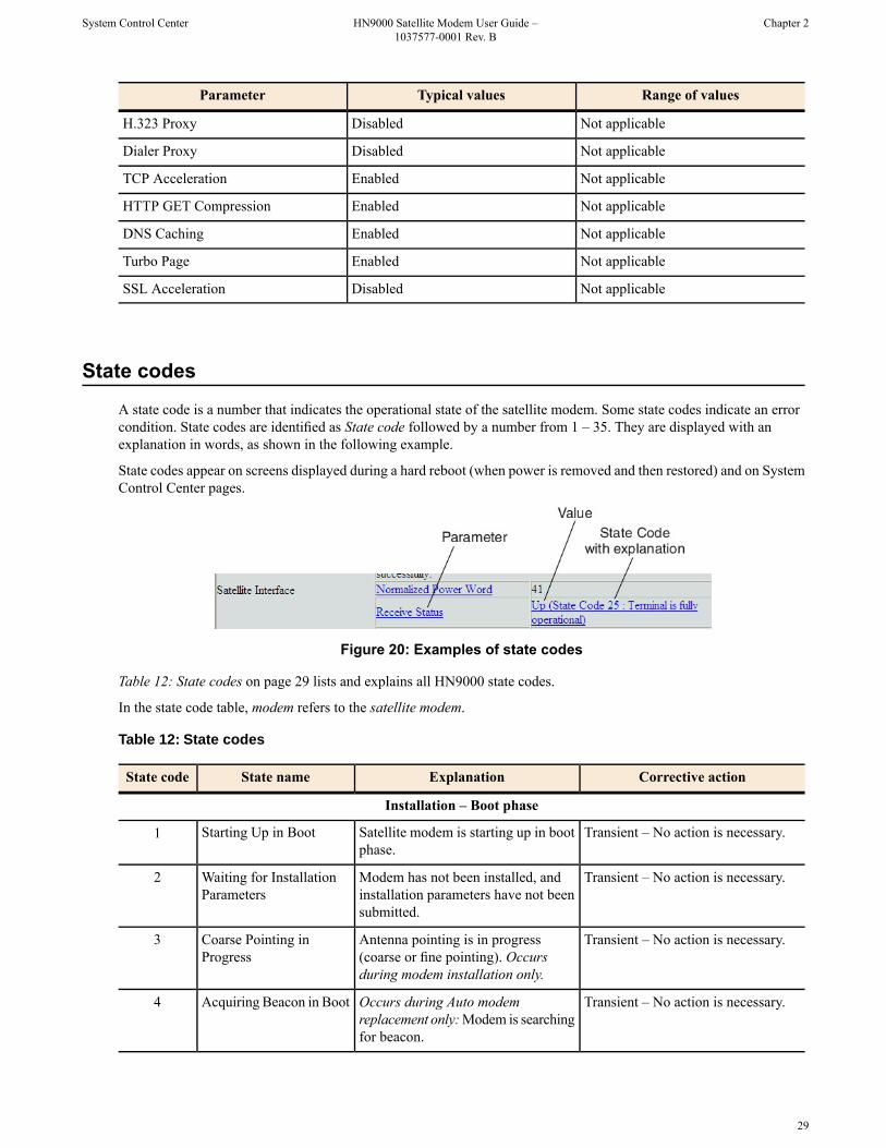
A state code is a number that indicates the operational state of the satellite modem. Some state codes indicate an errorcondition. State codes are identified as State code followed by a number from 1 – 35. They are displayed with anexplanation in words, as shown in the following example.
State codes appear on screens displayed during a hard reboot (when power is removed and then restored) and on SystemControl Center pages.
Figure 20: Examples of state codes
Table 12: State codes on page 29 lists and explains all HN9000 state codes.
In the state code table, modem refers to the satellite modem.
Table 12: State codes
Corrective actionExplanationState nameState code
Installation – Boot phase
Transient – No action is necessary.Satellite modem is starting up in bootphase.
Starting Up in Boot1
Transient – No action is necessary.Modem has not been installed, andinstallation parameters have not beensubmitted.
Waiting for InstallationParameters
2
Transient – No action is necessary.Antenna pointing is in progress(coarse or fine pointing). Occursduring modem installation only.
Coarse Pointing inProgress
3
Transient – No action is necessary.Occurs during Auto modemreplacement only:Modem is searchingfor beacon.
Acquiring Beacon in Boot4
29
Chapter 2HN9000 Satellite Modem User Guide –1037577-0001 Rev. B
System Control Center

Corrective actionExplanationState nameState code
Transient – No action is necessary.Occurs during Auto modemreplacement only:Modem is searchingfor point-to-point signal.
Acquiring PTP SNR inBoot
5
Installer should switch polarization.Modem is waiting for installer toswitch uplink polarization at the radio
Waiting for UplinkPolarization Change
6
assembly. Occurs during installationonly.
Transient – No action is necessary.Modem is in boot phase. Downlinkhas been established; that is, beacon
Downlink Established inBoot
7
is being tracked and transmissioninformation packets are beingreceived.
Transient – No action is necessary.Modem is in boot phase and is waitingfor indirect and direct managementpackets.
Waiting for MIPs in Boot8
Transient – No action is necessary.Modem is in boot phase and isdownloading commissioning software.
DownloadingCommissioning Software
9
Installer must complete validation.Modem is waiting for antennapointing validation to complete.Occurs during installation only.
Waiting for AntennaPointing Complete
10
Installation – Commissioning phase
Transient – No action is necessary.Modem is starting up incommissioning phase.
Starting Up inCommissioning
11
Transient – No action is necessary.Modem is in commissioning phase.Downlink has been established; that
Downlink Established inCommissioning
12
is, beacon is being tracked andtransmission information packets arebeing received.
Transient – No action is necessary.Modem is in commissioning phaseand is waiting for indirect and directmanagement packets.
Waiting for MIPs inCommissioning
13
Transient – No action is necessary.Modem is in commissioning phase.Probing is in progress. Occurs duringinstallation only.
Probing in Progress14
Occurs only during installation.Modem is in commissioning phase.Probing has failed.
Probing Failure15
Transient – No action is necessary.Modem is in commissioning phase.Modem is registering with the NOCC.
Registering ST16
Occurs only during installation.Modem is in commissioning phase:registration with the NOCC has failed.
ST Registration Failure17
Transient – No action is necessary.Modem is in commissioning phase;modem is waiting for capacity keysfrom the NOCC.
Waiting for CapacityKeys
18
30
System Control CenterHN9000 Satellite Modem User Guide –1037577-0001 Rev. B
Chapter 2

Corrective actionExplanationState nameState code
Transient – No action is necessary.Modem is in commissioning phase;modem is reconciling profiles with theNOCC.
Reconciling Profiles inCommissioning
19
Transient – No action is necessary.Modem is in commissioning phaseand is downloading operationalsoftware.
Downloading OperationalSoftware
20
Note: State codes 1 – 20 appear only while the modem is being installed or during a hard reboot (resulting from powerbeing removed and then restored).
Operational phase
Transient – No action is necessary.Modem is starting up in operationalphase.
Starting Up in Operation21
Transient – No action is necessary.Modem is in operational phase.Downlink has been established; that
Downlink Established inOperational
22
is, beacon is being tracked andtransmission information packets arebeing received.
Transient – No action is necessary.Modem is in operational phase and iswaiting for indirect and directmanagement packets.
Waiting for MIPs inOperational
23
Transient – No action is necessary.Modem is in operational phase.Profiles are being distributed tovarious subsystems.
Reconciling Profile inOperational
24
Steady state – No action is necessary.Modem is fully operational.Fully Operational (normaloperation)
25
Error codes
Make sure the SAT. IN and SAT.OUT cable connections are finger
Rx cable connectivity tests havefailed.
Rx Connectivity Down26
tight. If the problem persists, call yourservice provider to verify cabling andpointing.
Call your service provider to verifycabling and pointing.
Modem is unable to track beacon.No Beacon27
Call your service provider to verifycabling and pointing.
Modem is not receiving transmissioninformation packets from satellite.
No TIPs28
Call your service provider to verifycabling and pointing.
Tx cable connectivity tests have failed.Tx Connectivity Down29
Rain or snow can cause this condition.If it continues during clear weather,
Bad slots are transmissions from themodem that are not received by the
Too Many Bad Slots30
call your service provider to verifycabling and pointing.
satellite. State code 30 indicates apercentage of bad slots within the lasthour that exceeds a preset value.
Transient – No action is necessary.Transmitter has been shut down dueto ECL. ECL measures total
ECL Active31
31
Chapter 2HN9000 Satellite Modem User Guide –1037577-0001 Rev. B
System Control Center

Corrective actionExplanationState nameState code
Because home installations use lowerwattage radios, home users are notlikely to see this condition.
transmitted power over 30-minuteperiods and turns off the transmitterif the total power exceeds a presetlimit imposed by the FCC.
Restricted states (NOCC-imposed restrictions)
Call your service provider.Modem has been barred fromtransmitting by the NOCC. Possible
Barred32
reasons for barring includeinterference isolation, uplink failure,or government order.
Call your service provider.Modem has been put in a suspendedstate by the NOCC. This occurs if a
Suspended33
customer’s bill is overdue or if serviceis terminated.
Call your service provider.Modem has been put in maintenancestate by the NOCC.
Maintenance34
Call your service provider.Modem has been put in out-of-servicestate by the NOCC.
Out of Service35
Viewing the state codes listTo view a list of state codes with an explanation of each code:
1. Click the underlined state code number.
32
System Control CenterHN9000 Satellite Modem User Guide –1037577-0001 Rev. B
Chapter 2

A pop-up window appears that briefly identifies each state code. If you do not see the pop-up window, it may behidden by other windows; if this happens, minimize other open windows.
2. Scroll down to see the entire list of state codes.
Connectivity Test page
You can use the Connectivity Test page to test the connection between the satellite modem and the satellite. Instructionsfor the test are provided on the screen. No special configuration is required.
Figure 21: Terminal Connectivity Test page
For details about this test, see Testing connectivity to the satellite on page 44.
33
Chapter 2HN9000 Satellite Modem User Guide –1037577-0001 Rev. B
System Control Center


Chapter
3HughesNet Tools
HughesNet Tools is a suite of software tools installed on the computer that isconnected to the satellite modem during service activation. If for any reason
Topics:
• Launching HughesNet Tools HughesNet Tools is not installed on your computer, you can download it from• HughesNet Tools home page www.myhughesnet.com. (Click the HughesNet Customer Care link, click
Tools, and then clink the link to download HughesNet Tools.)
HughesNet Tools:
• Can help you solve Internet browsing problems.• Provides enhanced Internet security and improved performance for your
computer.• Provides convenient access to helpful support documents and phone numbers
for contacting Hughes Customer Care.
35

Launching HughesNet Tools
To launch HughesNet Tools from the Windows Start menu, click Start Programs HughesNet Tools.
You can also launch HughesNet Tools by double-clicking the HughesNet Tools shortcut on yourcomputer desktop or by double-clicking the similar icon in the system tray in the lower right corner of your computerscreen.
The HughesNet Tools home page opens, as shown in Figure 22: HughesNet Tools home page on page 36.
HughesNet Tools home page
The HughesNet Tools home page includes links to several useful tools, utilities, and information sites. Several of thetools run automatic tests when you click the link.
Figure 22: HughesNet Tools home page
I Have a Technical ProblemI Have a Technical Problem includes the following links:
I amUnable to Browse the Internet – This tool tests your Internet connection. If the test fails, the tool suggests optionsfor solving the problem.
I Cannot Send or Receive Email – This tool tests your e-mail account, and attempts to correct the problem.
36
HughesNet ToolsHN9000 Satellite Modem User Guide –1037577-0001 Rev. B
Chapter 3

Support LibraryIn the Support Library area of the screen, the link Browse All Support Documents helps you navigate to supportdocuments for Internet Explorer and Outlook Express and Hughes How to articles on various topics.
Helpful ToolsHelpful Tools includes the following links:
Utilities – These utilities can improve the performance of your computer and/or Internet browser.
Configure Your Email Client – This tool configures your computer to use any of several popular email programs.
Security – This tool takes certain steps to improve the security of your computer. It scans your computer to see whatsecurity software is installed. It asks you if you would like to install a trial subscription to the ZoneAlarm Security Suite.
Contact Support – If you click the Contact Support link, HughesNet Tools automatically runs tests to see if it candetermine and correct any problems with your computer and Internet browser configuration. If it cannot find and correctany problems, HughesNet Tools presents a phone number you can call for assistance.
37
Chapter 3HN9000 Satellite Modem User Guide –1037577-0001 Rev. B
HughesNet Tools


Chapter
4LEDs
The satellite modem has a vertical row of LEDs on the front panel and smallLEDs on the Ethernet port on the back of the modem. The LEDs provideinformation about the satellite modem’s operating status.
Topics:
• Front panel LEDs• LAN port LEDs
39

Front panel LEDs
The satellite modem has five LEDs on the front panel, as shown in Figure 23: Front panel LEDs on the HN9000 modemon page 40. By their appearance—on, off, or blinking—the LEDs indicate the modem’s operating status.
Figure 23: Front panel LEDs on the HN9000 modem
Table 13: Front panel LED indications on page 40 explains what the modem status is when the LEDs are on, off, orblinking. On means the LED is continuously lit. Blinking means the LED is usually on, but intermittently turns offbriefly.
Table 13: Front panel LED indications
Corrective actionSatellite modem statusAppearanceLED
The modem’s LAN port is connected to anothernetwork device such as your computer.
OnLAN
Check network connections.Problem with the LAN configuration; requiresuser intervention.
Off
The modem is able to transmit.OnTransmit
The modem is transmitting data packets to thenetwork satellite.
Blinking
Check transmit cable connection.Problem in the transmit path.Off
Signal quality is good.OnReceive
The modem is receiving data packets from thesatellite.
Blinking
40
LEDsHN9000 Satellite Modem User Guide –1037577-0001 Rev. B
Chapter 4

Corrective actionSatellite modem statusAppearanceLED
Check receive cable connection.Problem in the receive path.Off
Ready to handle user traffic.OnSystem
In boot or commissioning phase.Blinking
Not ready to service user traffic.Off
The satellite modem is receiving power from itspower supply.
On – bluePower
Make sure the environmentaltemperature is within range, that the
Modem temperature is too hot.
(If the modem overheats, it turns off. When itcools it recovers to operational status.)
On – red
modem is positioned vertically, andthat its vents are not blocked.
Check power connection.Not receiving power.Off
Bold type indicates LED appearance during normal operation.
LAN port LEDs
Green and orange LEDs on the LAN (Ethernet) port on the modem's rear panel indicate link status and speed, as explainedin Figure 24: LAN port LEDs on page 41.
Figure 24: LAN port LEDs
41
Chapter 4HN9000 Satellite Modem User Guide –1037577-0001 Rev. B
LEDs


Chapter
5Troubleshooting
If you encounter a problem with the satellite modem, refer to the relevanttroubleshooting procedure or procedures in the sections that follow. If you cannotcorrect the problem, contact Hughes Customer Care.
Topics:
• Rescue switch• Cannot Access the System
Control CenterFor support options and contact information, see Contact Information on pagexv.
• Testing connectivity to thesatellite Other sections in this Guide that contain troubleshooting information are listed
below:• Hot cable connector• For explanation of state codes, which appear on various screens, see Table
12: State codes on page 29.• Checking for viruses and firewall
issues• For explanation of red flags, see Red flag indicator on page 15.• Improper settings on the computer connected to the satellite modem can
cause problems. For instructions on configuring a computer to work properlywith the modem see Computer settings on page 49.
43

Rescue switch
Do not use the recessed rescue switch on the modem’s rear panel unless you are a qualified technician. Pressing thisswitch could cause the modem to become inoperable.
Cannot Access the System Control Center
Follow these steps if you cannot access the System Control Center after installation of the satellite modem.
1. If the modem is using a private IP address, confirm that DHCP is enabled on the computer.This procedure is explained in Configuring a computer to use DHCP on page 51.
2. Open a web browser on a computer connected to the satellite modem.3. In the browser address bar, type www.systemcontrolcenter.com or 192.168.0.1 and press Enter.
Note: To use 192.168.0.1, the satellite modem must be configured for a private IP address, and DHCP mustbe enabled on the computer.
If the System Control Center does not appear, continue with the remaining steps.
4. Make sure that the satellite modem is powered up. The Power and LAN LEDs should be continuously lit—exceptthat the LAN LED may blink if there is LAN activity.
5. Make sure the DC power cord adapter is securely attached to the satellite modem.6. If the LEDs are off, make sure the Ethernet cable is securely attached to the satellite modem and the computer.7. If you still cannot access the System Control Center, contact Hughes Customer Care for assistance.
Testing connectivity to the satellite
If you have problems connecting to the Internet, you can use the Connectivity Test page to test connectivity betweenthe modem and the satellite. This connectivity test sends test messages on a loop from the modem to the satellite andback to the modem, as shown in Figure 25: Satellite loopback connectivity test on page 45. If the test succeeds, it verifiesthat the modem can connect to the satellite.
44
TroubleshootingHN9000 Satellite Modem User Guide –1037577-0001 Rev. B
Chapter 5

Figure 25: Satellite loopback connectivity test
1. To conduct this test from any System Control Center page, click Connectivity Test in the left panel.The initial Terminal Connectivity Test page appears.
Figure 26: Terminal Connectivity Test page
2. Click Start Test.You may see a screen that asks you to wait while the test is conducted. When the test finishes, the Connectivity Testresults page appears.
45
Chapter 5HN9000 Satellite Modem User Guide –1037577-0001 Rev. B
Troubleshooting

Figure 27: Connectivity Test results page
If the number of messages sent equals the number of messages received, the test is successful—there is goodconnectivity between the remote modem and the satellite.
If the number of messages received is greater than zero but not equal to the number of messages sent, you havephysical connectivity to the satellite, but if this test result persists, you may have an access problem.
Typically the delay time (time message is sent until it is received) is approximately 1 second. The screen shows theminimum, average, and maximum delay times for the test messages in milliseconds. Most important is whether allmessages are received or not.
For additional information, see How to interpret these results on the test results page.
Hot cable connector
If the connector on either the transmit or receive cable feels hot to the touch, the connector may be loose or otherwisedefective. Troubleshoot this problem as follows:
1. Remove power from the satellite modem by unplugging the power supply AC power cord from the surge protectoror AC outlet.
To remove power from the satellite modem, always unplug the AC power cord from the power source (power outlet,power strip, or surge protector). Do not remove the DC power cord from the modem’s rear panel. Doing so couldresult in an electrical shock or damage to the modem.
2. Allow the cable connector to cool for at least 5 min.3. Make sure the cable connector feels cool.4. Make sure the connector is securely attached to the cable and properly aligned. If it is cross-threaded, remove it and
reattach it. The connector should be finger tight with no play.
46
TroubleshootingHN9000 Satellite Modem User Guide –1037577-0001 Rev. B
Chapter 5

Note: The satellite modem may operate correctly when first installed, even if the transmit and receive cableconnectors are not adequately tightened. However, problems could develop later. Therefore, correct operationof the modem is not an indication that the cables are adequately tightened.
5. Reapply power to the modem by plugging the power supply back into the surge protector or AC outlet.
A suitable surge protector is recommended to protect the satellite modem from possible damage due to power surges.
6. Wait 5 min.7. Check the connector to see if it is hot.
If the connector is still hot, it may be defective and should be replaced.
Checking for viruses and firewall issues
If you have confirmed all connections but still cannot access the Internet, check the computer (and any other computerson the same network) for viruses. If you find a virus, delete or disable it, then try to browse the Internet again.
If you are using a firewall, refer to the firewall documentation and make sure none of its settings are blocking access toeither the Internet or the Hughes servers. Make sure you are using the latest version of any anti-virus and/or firewallsoftware.
47
Chapter 5HN9000 Satellite Modem User Guide –1037577-0001 Rev. B
Troubleshooting


Appendix
AComputer settings
For proper operation of the satellite modem, you may have to change certain settings on the computer that is connectedto the modem.
Instructions are provided for:
• Configuring a computer to support DHCP• Configuring a computer to use a public IP address• Disabling a web browser's proxy connection
These procedures are explained in the sections that follow.
Understanding the modem address and computer address
The satellite modem and any computer or computers that connect to it must each have their own identifying networkaddress. This network address is known as an IP address. An IP address may be dynamic, meaning that it can change,or static, meaning that it is fixed—it does not change. An IP address may also be public (or routable), meaning that itcan be used on the Intranet. A private IP address works on an internal network but not over the Internet. However, togain access to the Internet, private addresses may be converted by a network address translation (NAT) service to apublic IP address that can be used on the Internet. Both private and public addresses can be dynamic or static, althoughtypically a private IP address is dynamic and a typically a public IP address is static.
Both the modem and a connected computer can have either type of address—private or public. The type used dependson requirements a customer might have and their service plan. A public IP address or addresses are available only ifthey are specified in the service plan. Typically home users use a private IP address, but some home users use a publicIP address.
To find specific address information, go to the System Control Center System Information page Figure 18: TerminalStatus page (top part) on page 26. Scroll down until you see Addressing in the left column. Look at the first threeparameters in the Addressing field, as shown in the following two examples.
Private IP addresses
Figure 28: Example of Addressing parameters showing available private IP addresses on page 49 is an example ofSystem Information page address parameters for a satellite modem with a service plan that provides private IP addresses.
Figure 28: Example of Addressing parameters showing available private IP addresses
In this example, the satellite modem is assigned a private IP address (LAN Port Address) of 192.168.0.1.
49

There are 253 available private IP addresses that can be assigned to computers connecting to the satellite modem. Theseaddresses are in the range from 192.168.0.2 to 192.168.0.254 (the Last Usable IP Address).
Public IP address
Figure 29: Example of Addressing parameters showing one available public IP address on page 50 is an example ofSystem Information page address parameters for a satellite modem with a service plan that provides one public IP address.Some service plans provide multiple public IP addresses.
Figure 29: Example of Addressing parameters showing one available public IP address
In this example, the satellite modem is assigned the public IP address (LAN Port Address) 97.73.73.65. The modem’sDHCP server has only one public IP address to assign to a connecting computer: 97.73.73.66 (the Last Usable IP Address).
For instructions on configuring a public IP address on your computer, see the applicable section in Configuring acomputer for a public IP address on page 58. Find the section that applies to your computer operating system.
Multiple public IP addresses
If a service plan provides more than one public IP address, the range (or difference) from the LAN Port Address to theLast Usable IP Address will be greater than one. For example, if the LAN Port Address is 97.73.73.65 and the LastUsable IP Address is 97.73.73.70, the range (or difference) is 5, meaning there are five available public IP addresses.
If you don't know the modem’s public IP address…To access the satellite modem when the service plan provides a public IP address, you need to know the public IP addressof the satellite modem (the LAN Port Address). If you do not know the LAN Port Address (and you cannot access theSystem Information page), you can set a link local address on your computer as explained below:
1. Use the Windows Control Panel on the connected computer to open the Local Area Connection Properties dialogand then the Internet Protocol (TCP/IP) Properties dialog. If you need more specific instructions, see Configuring acomputer for a public IP address on page 58.
2. In the Internet Protocol Properties dialog, click Use the following IP address.3. Enter the following:
a) In the IP address field, type 169.254.10.10.b) Typically the Subnet mask field auto-populates to 255.255.0.0. If it does not, enter this value manually.c) In the Default gateway field, type 169.254.0.1.d) In the Preferred DNS server field, type 66.82.4.8.e) Click OK twice to close the Internet Protocol Properties dialog and the Network Connections dialog.
4. With the computer configured as instructed above, type 169.254.0.1 in your browser address window to open theSystem Control Center.If you click the link on the System Control Center home page for the System Information page, you can read themodem’s IP address in the Addressing section. The LAN Port Address is the modem’s IP address.
5. Record the LAN Port Address and the Last Usable IP Address.
Now you can enable DHCP on your computer (by selecting Obtain an IP Address automatically in the InternetProtocol Properties dialog). Then, the modem will dynamically assign a public IP address to the computer.
Alternatively, if you want to assign a particular public IP address to your computer, you can set that public IP addresson your computer. To configure the public address, see Configuring a computer for a public IP address on page 58.
50
Computer settingsHN9000 Satellite Modem User Guide –1037577-0001 Rev. B
Appendix A
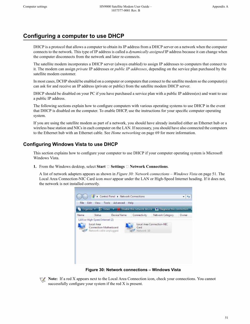
Configuring a computer to use DHCP
DHCP is a protocol that allows a computer to obtain its IP address from a DHCP server on a network when the computerconnects to the network. This type of IP address is called a dynamically assigned IP address because it can change whenthe computer disconnects from the network and later re-connects.
The satellite modem incorporates a DHCP server (always enabled) to assign IP addresses to computers that connect toit. The modem can assign private IP addresses or public IP addresses, depending on the service plan purchased by thesatellite modem customer.
In most cases, DCHP should be enabled on a computer or computers that connect to the satellite modem so the computer(s)can ask for and receive an IP address (private or public) from the satellite modem DHCP server.
DHCP should be disabled on your PC if you have purchased a service plan with a public IP address(es) and want to usea public IP address.
The following sections explain how to configure computers with various operating systems to use DHCP in the eventthat DHCP is disabled on the computer. To enable DHCP, use the instructions for your specific computer operatingsystem.
If you are using the satellite modem as part of a network, you should have already installed either an Ethernet hub or awireless base station and NICs in each computer on the LAN. If necessary, you should have also connected the computersto the Ethernet hub with an Ethernet cable. See Home networking on page 69 for more information.
Configuring Windows Vista to use DHCPThis section explains how to configure your computer to use DHCP if your computer operating system is MicrosoftWindows Vista.
1. From the Windows desktop, select Start Settings Network Connections.
A list of network adapters appears as shown in Figure 30: Network connections – Windows Vista on page 51. TheLocal Area Connection-NIC Card icon must appear under the LAN or High-Speed Internet heading. If it does not,the network is not installed correctly.
Figure 30: Network connections – Windows Vista
Note: If a red X appears next to the Local Area Connection icon, check your connections. You cannotsuccessfully configure your system if the red X is present.
51
Appendix AHN9000 Satellite Modem User Guide –1037577-0001 Rev. B
Computer settings

2. Right-click the Local Area Connection-NIC Card icon, which represents the satellite modem network connection,and select Properties.
The Local Area Connection-NIC Card Properties dialog appears as shown in Figure 31: Local Area ConnectionProperties – Windows Vista on page 52.
Note: Depending on the computer's security settings, a pop-up User Account Control message may appear,requesting that you confirm the action before proceeding. If you see this message, click Continue to proceed.
Figure 31: Local Area Connection Properties – Windows Vista
3. Ensure that both Client for Microsoft Networks and Internet Protocol (TCP/IP) are installed and checked as shown.4. If NetBEUI is installed and checked, uncheck it or uninstall it.5. Highlight the appropriate TCP/IP connection. Be careful not to uncheck the checkbox.6. Click Properties.
The Internet Protocol Properties dialog appears as shown in Figure 32: Internet Protocol Properties – WindowsVista on page 52.
Figure 32: Internet Protocol Properties – Windows Vista
52
Computer settingsHN9000 Satellite Modem User Guide –1037577-0001 Rev. B
Appendix A

7. Ensure that both the Obtain an IP address automatically and Obtain DNS server address automatically options areselected.
8. Click OK.9. Confirm that you have an IP address:
a) Click Start Run.b) Type cmd and click OK.c) Type ipconfig/renew and press Enter.d) Make sure an IP address is shown on the line that starts with IP Address.
Configuring Windows XP to use DHCPThis section explains how to configure your computer to use DHCP if your computer operating system is MicrosoftWindows XP.
1. From the Windows desktop, select Start Settings Control Panel.2. Double-click the Network and Dialup Connections icon.
Note: If Control Panel is in category view, select Network and Internet Connections; then select NetworkConnections.
A list of network adapters appears as shown in Figure 33: Network connections – Windows XP on page 53. A LocalArea Connection icon must appear under the LAN or High-Speed Internet heading. If it does not, the network is notinstalled correctly.
Figure 33: Network connections – Windows XP
Note: If a red X appears next to the Local Area Connection icon, check your connections. You cannotsuccessfully configure your system if the red X is present.
3. Right-click the Local Area Connection icon that represents the network adapter connecting the computer to theSatellite Gateway, and select Properties.The Local Area Connection Properties dialog appears as shown in Figure 34: Local Area Connection Properties –Windows XP on page 54.
53
Appendix AHN9000 Satellite Modem User Guide –1037577-0001 Rev. B
Computer settings

Figure 34: Local Area Connection Properties – Windows XP
4. Ensure that both Client for Microsoft Networks and Internet Protocol (TCP/IP) are installed and checked as shown.5. If NetBEUI is installed and checked, uncheck it or uninstall it.6. Highlight Internet Protocol (TCP/IP). Be careful not to uncheck the checkbox.7. Click Properties.
The Internet Protocol Properties dialog appears as shown in Figure 35: Internet Protocol Properties – Windows XPon page 54.
Figure 35: Internet Protocol Properties – Windows XP
8. On the General tab, ensure that both the Obtain an IP address automatically and Obtain DNS server addressautomatically options are selected. If not, select them.
9. Click OK.10. Confirm that you have an IP address:
a) Click Start Run.b) Type cmd and click OK.
54
Computer settingsHN9000 Satellite Modem User Guide –1037577-0001 Rev. B
Appendix A
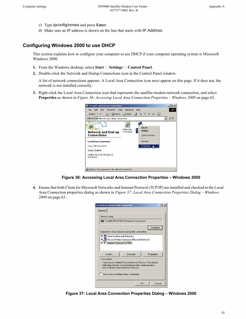
c) Type ipconfig/renew and press Enter.d) Make sure an IP address is shown on the line that starts with IP Address.
Configuring Windows 2000 to use DHCPThis section explains how to configure your computer to use DHCP if your computer operating system is MicrosoftWindows 2000.
1. From the Windows desktop, select Start Settings Control Panel.2. Double-click the Network and Dialup Connections icon in the Control Panel window.
A list of network connections appears. A Local Area Connection icon must appear on this page. If it does not, thenetwork is not installed correctly.
3. Right-click the Local Area Connection icon that represents the satellite modem network connection, and selectProperties as shown in Figure 36: Accessing Local Area Connection Properties – Windows 2000 on page 62.
Figure 36: Accessing Local Area Connection Properties – Windows 2000
4. Ensure that both Client for Microsoft Networks and Internet Protocol (TCP/IP) are installed and checked in the LocalArea Connection properties dialog as shown in Figure 37: Local Area Connection Properties Dialog – Windows2000 on page 63.
Figure 37: Local Area Connection Properties Dialog – Windows 2000
55
Appendix AHN9000 Satellite Modem User Guide –1037577-0001 Rev. B
Computer settings

5. If NetBEUI is installed and checked, uncheck it or uninstall it.6. Highlight Internet Protocol (TCP/IP). Be careful not to uncheck the checkbox.7. Click Properties.
The Internet Protocol Properties dialog appears as shown in Figure 38: Internet Protocol Properties – Windows2000 on page 63.
Figure 38: Internet Protocol Properties – Windows 2000
8. On the General tab, ensure that both the Obtain an IP address automatically and Obtain DNS server addressautomatically options are selected. If not, select them.
9. Click OK to close the dialog box.10. Click OK again to save the settings and close the Local Area Connection Properties dialog.11. Confirm that you have an IP address:
a) Click Start Run.b) Type cmd and click OK.c) Type ipconfig/renew and press Enter.d) Make sure an IP address is shown on the line that starts with IP Address.
Configuring a Mac computer to use DHCPThis section explains how to configure your computer to use DHCP if you are using an Apple Mac computer.
1. From the Mac interface, select System Preferences.The System Preferences menu appears as shown in Figure 39: Mac System Preferences menu on page 57.
56
Computer settingsHN9000 Satellite Modem User Guide –1037577-0001 Rev. B
Appendix A

Figure 39: Mac System Preferences menu
2. Under Internet & Network, click the Network icon (shown circled in the figure).The Network screen appears as shown in Figure 36: Accessing Local Area Connection Properties – Windows 2000on page 62.
Figure 40: Mac Network screen
3. Ensure that the TCP/IP tab is selected.4. Select Using DHCP from the Configure drop-down list as shown in Figure 41: Select DHCP from the configure
drop-down menu on page 58.The IP Address field becomes disabled.
57
Appendix AHN9000 Satellite Modem User Guide –1037577-0001 Rev. B
Computer settings

Figure 41: Select DHCP from the configure drop-down menu
5. Click Apply Now to close the screen.
Configuring a computer for a public IP address
If it is desired or necessary for a computer to have a fixed or permanent IP address, the computer should be configuredfor a public IP address. For more information about IP addresses, see Understanding the modem address and computeraddress on page 49.
To configure the computer to support a public IP address, you manually enter the following information:
• IP address. You need a valid IP address for the computer. If the computer is part of a LAN, each computer on theLAN must have its own unique address.
• Subnet Mask. This is the subnet mask assigned to your satellite modem. You should have recorded this informationin your Quick Start Guide during the registration process. You can also obtain it from the System Information pageof the System Control Center.
• Default Gateway. This is the IP address of the satellite modem. You should have recorded this information in yourQuick Start Guide during the registration process. You can also obtain it from the System Information page of theSystem Control Center.
Note: If your satellite modem is to be connected to a router, you must also configure the router with the public IPaddress. Refer to the router’s instructions. You must then configure support for DHCP on all computers that areconnected to the router.
Configuring Windows Vista – Public IP addressPerform the following procedures to configure a computer running on Windows Vista for a public IP address.
1. From the Windows desktop, select Start Settings Network Connections.
A list of network adapters appears as shown in Figure 42: Network connections – Windows Vista on page 59. ALocal Area Connection-NIC Card icon must appear under the LAN or High-Speed Internet heading. If it does not,the network is not installed correctly.
58
Computer settingsHN9000 Satellite Modem User Guide –1037577-0001 Rev. B
Appendix A

Figure 42: Network connections – Windows Vista
Note: If a red X appears next to the Local Area Connection icon, check your connections. You cannotsuccessfully configure your system if the red X is present.
2. Right-click the icon that represents the satellite modem network connection, and select Properties.
The Local Area Connection-NIC Card Properties dialog appears as shown in Figure 43: Local Area ConnectionProperties – Windows Vista on page 59.
Note: Depending on your security settings, a pop-up User Account Control message may appear, requestingthat you confirm the action before proceeding. If you see this message, click Continue to proceed.
Figure 43: Local Area Connection Properties – Windows Vista
3. Ensure that both Client for Microsoft Networks and Internet Protocol (TCP/IP) are installed and checked as shown.4. If NetBEUI is installed and checked, uncheck it or uninstall it.5. Highlight the appropriate TCP/IP connection. Be careful not to uncheck the checkbox.6. Click Properties.
59
Appendix AHN9000 Satellite Modem User Guide –1037577-0001 Rev. B
Computer settings

The Internet Protocol Properties dialog appears as shown in Figure 44: Internet Protocol Properties – WindowsVista on page 60.
Figure 44: Internet Protocol Properties – Windows Vista
7. On the General tab, select Use the following IP address.8. Enter the IP address and subnet mask in the appropriate fields.
If you do not know what public IP address or range of addresses is available for use, see Understanding the modemaddress and computer address on page 49.
9. Select Use the following DNS server addresses.10. Enter 66.82.4.8 in the Preferred DNS server field.11. Click OK.
Configuring Windows XP – Public IP addressPerform the following procedures to configure a computer running on Windows XP for a public IP address.
1. From the Windows desktop, select Start Settings Control Panel.2. Double-click the Network Connections icon in the Control Panel window.
A list of network adapters appears. A Local Area Connection icon must appear under the LAN or High-Speed Internetheading. If it does not, the network is not installed correctly.
3. Right-click the Local Area Connection icon that represents the satellite modem network connection, and selectProperties as shown in Figure 45: Accessing Local Area Connection Properties – Windows XP on page 61.
60
Computer settingsHN9000 Satellite Modem User Guide –1037577-0001 Rev. B
Appendix A

Figure 45: Accessing Local Area Connection Properties – Windows XP
Note: If a red X appears next to the Local Area Connection icon, check your connections. You cannotsuccessfully configure your system if the red X is present.
4. Ensure that both Client for Microsoft Networks and Internet Protocol (TCP/IP) are installed and checked in the LocalArea Connection properties dialog as shown in Figure 46: Local Area Connection Properties Dialog – Windows XPon page 61.
Figure 46: Local Area Connection Properties Dialog – Windows XP
5. If NetBEUI is installed and checked, uncheck it or uninstall it.6. Highlight Internet Protocol (TCP/IP). Be careful not to uncheck the checkbox.7. Click Properties.
The Internet Protocol Properties dialog appears as shown in Figure 47: Internet Protocol Properties – Windows XPon page 62.
61
Appendix AHN9000 Satellite Modem User Guide –1037577-0001 Rev. B
Computer settings

Figure 47: Internet Protocol Properties – Windows XP
8. On the General tab, select Use the following IP address.9. Enter the IP address, subnet mask, and default gateway in the appropriate fields.
If you do not know what public IP address or range of addresses is available for use, see Understanding the modemaddress and computer address on page 49.
10. Select Use the following DNS server addresses. Enter 66.82.4.8 in the Preferred DNS server field.11. Click OK.
Configuring Windows 2000 – Public IP addressPerform the following procedures to configure a computer running on Windows 2000 for a public IP address.
1. From the Windows desktop, select Start Settings Control Panel.2. Double-click the Network and Dialup Connections icon in the Control Panel window.
A list of network adapters appears. A Local Area Connection iconmust appear on the page. If it does not, the networkis not installed correctly.
3. Right-click the Local Area Connection icon that represents the satellite modem network connection, and selectProperties as shown in Figure 36: Accessing Local Area Connection Properties – Windows 2000 on page 62.
Figure 48: Accessing Local Area Connection Properties – Windows 2000
62
Computer settingsHN9000 Satellite Modem User Guide –1037577-0001 Rev. B
Appendix A

4. Ensure that both Client for Microsoft Networks and Internet Protocol (TCP/IP) are installed and checked in the LocalArea Connection properties dialog as shown in Figure 37: Local Area Connection Properties Dialog – Windows2000 on page 63.
Figure 49: Local Area Connection Properties Dialog – Windows 2000
5. If NetBEUI is installed and checked, uncheck it or uninstall it.6. Highlight Internet Protocol (TCP/IP). Be careful not to uncheck the checkbox.7. Click Properties.
The Internet Protocol Properties dialog appears as shown in Figure 38: Internet Protocol Properties – Windows2000 on page 63.
Figure 50: Internet Protocol Properties – Windows 2000
8. On the General tab, select Use the following IP address.9. Enter the IP address and Subnet mask.
If you do not know what public IP address or range of addresses is available for use, see Understanding the modemaddress and computer address on page 49.
10. Enter the satellite modem IP address in the Default Gateway field.
63
Appendix AHN9000 Satellite Modem User Guide –1037577-0001 Rev. B
Computer settings

11. Enter 66.82.4.8 in the Preferred DNS server field.12. Click OK to close the dialog box.13. Click OK again to save the settings and close the Local Area Connection Properties dialog.
Configuring a Mac computer – Public IP addressPerform the following procedures to configure a Mac system for a public IP address.
1. From the Mac interface, select System Preferences.The System Preferences menu appears as shown in Figure 51: Mac System Preferences menu on page 64.
Figure 51: Mac System Preferences menu
2. Under Internet & Network, click the Network icon (shown circled in the figure).The Network screen appears as shown in Figure 52: Mac Network screen on page 65.
64
Computer settingsHN9000 Satellite Modem User Guide –1037577-0001 Rev. B
Appendix A
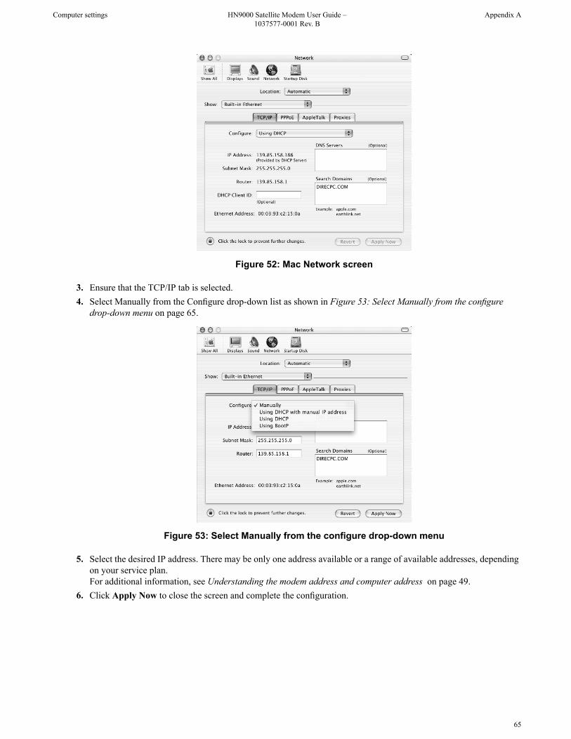
Figure 52: Mac Network screen
3. Ensure that the TCP/IP tab is selected.4. Select Manually from the Configure drop-down list as shown in Figure 53: Select Manually from the configure
drop-down menu on page 65.
Figure 53: Select Manually from the configure drop-down menu
5. Select the desired IP address. There may be only one address available or a range of available addresses, dependingon your service plan.For additional information, see Understanding the modem address and computer address on page 49.
6. Click Apply Now to close the screen and complete the configuration.
65
Appendix AHN9000 Satellite Modem User Guide –1037577-0001 Rev. B
Computer settings

Configuring proxy settings
If your web browser cannot connect to the Internet, check the browser's proxy settings. If the browser is configured forthe computer to use a proxy server to connect to the Internet, try changing the setting to not use a proxy server.
Configuring Internet Explorer to not use a proxy serverFollow these steps to configure Internet Explorer to not use a proxy server.
1. Turn the computer on and open Internet Explorer.2. Select Tools Internet Options .3. Select the Connections tab and click LAN settings.
The LAN settings dialog appears.
Figure 54: LAN settings – Internet Explorer
4. Uncheck the check box next to Use a proxy server for your LAN.5. Click OK.6. Close Internet Explorer and re-launch it to enable the changes.
Configuring Netscape to not use a proxy serverFollow these steps to configure Netscape Navigator to not use a proxy server.
1. Turn the computer on and open Netscape.2. Select Edit Preferences .
The Preferences window appears.3. In the Category pane on the left side of the window, select Advanced Proxies .
66
Computer settingsHN9000 Satellite Modem User Guide –1037577-0001 Rev. B
Appendix A

Figure 55: Proxy settings in Netscape Preferences window
4. In the Proxies pane on the right side of the window, select Direct connection to the Internet.5. Click OK.6. Close Netscape and re-launch it to enable the changes.
67
Appendix AHN9000 Satellite Modem User Guide –1037577-0001 Rev. B
Computer settings


Appendix
BHome networking
This information about networking is provided for home users.
You can connect multiple home computers and laptops to a single Internet connection. When connected to a properlyaligned antenna assembly, a satellite modem can provide satellite connectivity for multiple computers by using anEthernet or wireless LAN. Once the satellite modem and network are installed, every computer on the LAN can accessthe Internet through the satellite signal.
Note: Required home networking equipment other than the satellite modem is not included. For network setup,support and configuration, contact the network hardware manufacturer and/or operating system software developer.Hughes is not responsible for home network management or troubleshooting. Simultaneous use of high bandwidthapplications by multiple users may result in speed degradation. Speed and uninterrupted use of service are notguaranteed. Actual speeds may vary.
If you connect your satellite modem to a LAN, you must:
• Install and configure an Ethernet hub, router, or wireless network base station.• Install and configure a NIC in each computer to be connected. The NICs must be set to auto-negotiate. Refer to the
manufacturer’s installation instructions.• For wired networks, connect the computers to the Ethernet hub with Ethernet cable.
Note: You must complete these instructions for each computer or device that is to access the Internet over theLAN.
Wireless network basics
A wireless network is typically easy to install because it connects to a wireless base station through radio waves ratherthan cables. A wireless NIC must be installed in each computer. Wireless base stations and NICs are available at mostcomputer supply stores.
69
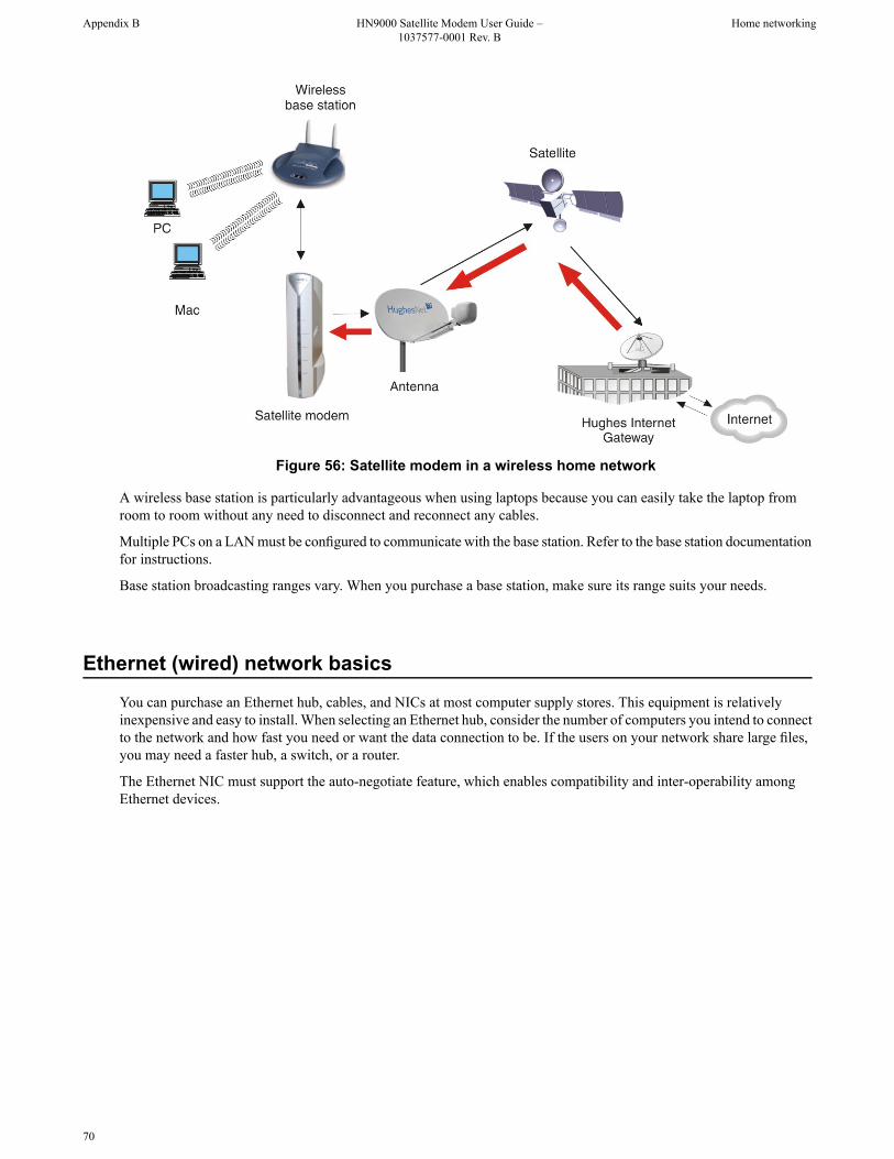
Figure 56: Satellite modem in a wireless home network
A wireless base station is particularly advantageous when using laptops because you can easily take the laptop fromroom to room without any need to disconnect and reconnect any cables.
Multiple PCs on a LAN must be configured to communicate with the base station. Refer to the base station documentationfor instructions.
Base station broadcasting ranges vary. When you purchase a base station, make sure its range suits your needs.
Ethernet (wired) network basics
You can purchase an Ethernet hub, cables, and NICs at most computer supply stores. This equipment is relativelyinexpensive and easy to install. When selecting an Ethernet hub, consider the number of computers you intend to connectto the network and how fast you need or want the data connection to be. If the users on your network share large files,you may need a faster hub, a switch, or a router.
The Ethernet NIC must support the auto-negotiate feature, which enables compatibility and inter-operability amongEthernet devices.
70
Home networkingHN9000 Satellite Modem User Guide –1037577-0001 Rev. B
Appendix B

Figure 57: Satellite modem in a wired Ethernet home network
Use at least a Category 5 Ethernet cable. You may consider using Category 5e to accommodate future enhancements.Ethernet cable with RJ-45 connectors at each end is usually available in lengths up to 50 ft. If you need a longer cable,you must terminate the cable using a kit that can be purchased at an electronics, computer, or home supply store. If youfeel unsure about installing Ethernet cable, contact a professional installer.
Run Ethernet cables behind walls whenever possible or secure them to floor baseboards and doorway frames. Do notuse staples to secure Ethernet cable.
Leave enough slack in the cable to accommodate possible future repair splices or moving of equipment.
71
Appendix BHN9000 Satellite Modem User Guide –1037577-0001 Rev. B
Home networking


Appendix
CConformance with standards and directives
The HN9000 satellite modem has been certified to conform to the standards shown in Table 14: HN9000 standardscompliance on page 73. Additional information follows the table.
Table 14: HN9000 standards compliance
StandardCategory
FCC Part 15 for the United StatesElectromagnetic Interference (EMI) standards
ICES-003 for Canada
UL60950-1 for the United StatesSafety standards
CAN/CSA-C22.2 No. 60950-1 for Canada
Electromagnetic interference (EMI)
This product conforms to EMI standards of the U.S. FCC and Canadian CSA. To ensure compliance with these standards,installers and users must follow the installation, maintenance, and configuration procedures in the installation guide anduser guide.
This is a class B product. In a domestic environment this product may cause radio interference in which case the usermay be required to take adequate measures.
FCC Part 15This section applies to the HN9000 satellite modem.
Standards to which Conformity is declared: FCC Part 15
The modem complies with Part 15 of the FCC Rules. Operation is subject to the following two conditions: (1) Thisdevice may not cause harmful interference, and (2) this device must accept any interference received, including interferencethat may cause undesired operation.
Responsible party’s name: Hughes Network System, LLC
Address: 11717 Exploration Lane, Germantown, MD 20876
Telephone: 1 (866) 347-3292
Trade name: HUGHES
73

Type of equipment: Two-way Hughes system
Model numbers: HN9000 (1500826-xxxx)
The two-way Hughes system (HN9000 ) complies with the Canadian ICES-003, Class B standard.
Canada Class B warningThis Class B digital apparatus complies with Canadian ICES-003.
Cet appareil numérique de la classe B est conforme á la norme NMB-003 du Canada.
Operational and safety requirements for Canada
In addition to the warnings and safety guidelines listed in this document, the following operating conditions apply tothe modem when used in Canada:
The Canadian Department of Communications label identifies certified equipment. This certification means that theequipment meets certain telecommunications network protective operational and safety requirements. The Departmentdoes not guarantee that the equipment will operate to the user’s satisfaction.
Before installing the equipment, users should make sure they are permitted connect to the facilities of the localtelecommunications company. The equipment must also be installed using an acceptable method of connection. In somecases, the company's inside wiring associated with a single line individual service may be extended by means of acertified connector assembly (telephone extension cord). The customer should be aware that compliance with the aboveconditions may not prevent degradation of service in some situations.
Repairs in CanadaRepairs to certified equipment should be made by an authorized Canadian maintenance facility designated by the supplier.Any repairs or alterations made by the user to this equipment, or equipment malfunctions, may give the telecommunicationscompany cause to request the user to disconnect the equipment.
Users should ensure for their own protection that the electrical ground connections of the power utility, telephone lines,and internal metallic water pipe system, if present, are connected together. This precaution may be particularly importantin rural areas.
Users should not attempt to make electrical ground connections themselves, but should contact the appropriate electricalinspection authority, or electrician, as appropriate.
74
Conformance with standards and directivesHN9000 Satellite Modem User Guide –1037577-0001 Rev. B
Appendix C

Appendix
DAcronyms used in this Guide
Alternating currentAC
American Wire GaugeAWG
CanadaCAN
Continental United StatesCONUS
Canadian Standards AssociationCSA
Direct currentDC
Dynamic Host Configuration ProtocolDHCP
Domain Name SystemDNS
Emission Control LogicECL
European UnionEU
Electromagnetic InterferenceEMI
Electronic serial numberESN
European UnionEU
Fair access policyFAP
Federal Communications CommissionFCC
HyperText Transfer ProtocolHTTP
Interference-Causing Equipment StandardICES
Internet Control Message ProtocolICMP
IdentifierID
Inter-facility linkIFL
Internet Group Management ProtocolIGMP
Internet ProtocolIP
Internet Router Discovery ProtocolIRDP
Internet service providerISP
A Hughes proprietary routing protocolISRP
Local area networkLAN
Left-hand circular polarizationLHCP
Limited Liability CompanyLLC
Management information packetMIP
75

Network address translationNAT
Extended User Interface (network transfer protocol)NetBEUI
Network interface cardNIC
(Hughes) Network Operations CenterNOC
(Hughes) Network Operations Control CenterNOCC
Outdoor unit (antenna and radio assembly)ODU
PEP Backbone Protocol (PEP – Performance Enhancing Proxy)PBP
Personal computerPC
Point-of-sale devicePOS
Point-to-pointPTP
Right-hand circular polarizationRHCP
Signal-to-noise ratioSNR
Signal quality factorSQF
Secure Sockets Layer (security protocol)SSL
Satellite terminal (an alternate name for satellite modem; used on some softwarescreens)
ST
Transmission Control ProtocolTCP
Transmission information packetTIP
UplinkUL
Underwriters Laboratory
Voltage, alternating currentVAC
Value added resellerVAR
76
Acronyms used in this GuideHN9000 Satellite Modem User Guide –1037577-0001 Rev. B
Appendix D

Index
AAddress, See IP addressAudience for this Guide xiii
BBrowser requirements 6Button links (System Control Center pages) 11
CCanada Class B warning 74Canadian safety standards 74Class B warning (Canada) 74Computer IP address 49Computer requirements 5Computer settings 49, 51, 58, 66
DHCP settings 51proxy settings 66public IP address 58
Conformance with standards and directives 73Connectivity test page 44Contact information xv, 37
DDHCP 44DHCP settings 51
EElectromagnetic interference 73Email
configuring 37resolving problems 36
EMI standards 73Error messages
state codes 14, 29Ethernet network, basic information 70
FFCC Part 15 73Firewall 47Front panel LEDs 40
GGateway, Internet 2
HHome networking 69
HughesNet Toolsdescription 35home page 36launching 36Support Library 37utilities 37
IInternet Gateway 2IP address 8, 26, 44, 49, 50, 58
available addresses for computers and other devices 49computer 49DHCP 44for opening System Control Center 8modem 49multiple 50not known 50private IP address 44, 49public IP address 49, 58System Information page Addressing section 26
LLAN port 4, 41
LEDs 41LEDs
front panel 40LAN port 41purpose 39
Links (System Control Center) 9, 11
MModem IP address 49Multiple-host configuration 2
NNetwork address translation 49Networking, home 69Networking requirements 6Network interface card 69
OOpening System Control Center 8Overview of the satellite modem 1
PParameters on System Control Center screens 13Position for operating modem 5Powering down the satellite modem 5
77
Power supply 4Private IP address 49Private network configuration 3Proxy settings 66Public IP address 49, 58
RReception Information page 19Red flag indicators 15, 18, 20, 23
Reception Information page 20System Status page 18Transmission Information page 23
Repairs in Canada 74Rescue switch 44
SSafety standards, Canadian 74Satellite loopback connectivity test 44Satellite modem overview 1Scope of this Guide xiiiSecurity 37Single-host configuration 2Specifications 3Standards and directives 73State codes 14, 29Support xv, 37Supported configurations 2Support Library 37System Control Center
button links 11common features 10description 7home page 9
text links 9links in left panel 13opening 8parameters, format 13
System Control Center (continued)Reception Information page 19shortcut 8Shortcut for System Control Center 8status and information screens, format 13System Information page 26System Status button colors 12System Status page 15Terminal Status page 23Transmission Information page 21
System Information page 26System Status button colors 12System Status page 15
TTerminal Status page 23Tests and testing, See TroubleshootingTransmission Information page 21Troubleshooting 36, 43, 44, 46
cannot access System Control Center 44hot cable connector 46testing connectivity to satellite 44Unable to Browse the Internet link 36
UUtilities 37
VViruses 47
WWireless network
basic information 69
78
Index


![3.1.2 internet inicio.ppt [Modo de compatibilidad]curso.unach.mx/preu/archivos/3_1_2_internet_inicio.pdf · Modem externoModem externo Modem internoModem interno Modem usb Modem Pc](https://img.pdfslide.net/doc/110x75/5e998aa7f5b663212a3953fd/312-internet-modo-de-compatibilidadcursounachmxpreuarchivos312internetiniciopdf.jpg)