Embed Size (px)
Citation preview
DEP SPECIFICATION
HUMAN FACTORS ENGINEERING – LABELLING OF FACILITIES, EQUIPMENT AND PIPING
DEP 30.00.60.21-Gen.
February 2012
ECCN EAR99
DESIGN AND ENGINEERING PRACTICE
© 2012 Shell Group of companies All rights reserved. No part of this publication may be reproduced, stored in a retrieval system, published or transmitted, in any form or by any means, without the prior
written permission of the copyright owner or Shell Global Solutions International BV.
This document contains information that is classified as EAR99 and, as a consequence, can neither be exported nor re-exported to any country which is under an embargo of the U.S. government pursuant to Part 746 of the Export Administration Regulations (15 C.F.R. Parts 746) nor can be made available to any national of such country. In addition, the information in this document cannot be exported nor re-exported to an end-user or for an end-use that is prohibited by Part 744 of the Export
Administration Regulations (15 C.F.R. Parts 744).
Co
pyr
igh
t S
hel
l Gro
up
of
Co
mp
anie
s. N
o r
epro
du
ctio
n o
r n
etw
ork
ing
per
mit
ted
wit
ho
ut
licen
se f
rom
Sh
ell.
No
t fo
r re
sale
This document has been supplied under license by Shell to:Petroleum Development Oman [email protected] 07/06/2015 09:56:38
ECCN EAR99 DEP 30.00.60.21-Gen. February 2012
Page 2
PREFACE
DEP (Design and Engineering Practice) publications reflect the views, at the time of publication, of Shell Global Solutions International B.V. (Shell GSI) and, in some cases, of other Shell Companies.
These views are based on the experience acquired during involvement with the design, construction, operation and maintenance of processing units and facilities. Where deemed appropriate DEPs are based on, or reference international, regional, national and industry standards.
The objective is to set the standard for good design and engineering practice to be applied by Shell companies in oil and gas production, oil refining, gas handling, gasification, chemical processing, or any other such facility, and thereby to help achieve maximum technical and economic benefit from standardization.
The information set forth in these publications is provided to Shell companies for their consideration and decision to implement. This is of particular importance where DEPs may not cover every requirement or diversity of condition at each locality. The system of DEPs is expected to be sufficiently flexible to allow individual Operating Units to adapt the information set forth in DEPs to their own environment and requirements.
When Contractors or Manufacturers/Suppliers use DEPs, they shall be solely responsible for such use, including the quality of their work and the attainment of the required design and engineering standards. In particular, for those requirements not specifically covered, the Principal will typically expect them to follow those design and engineering practices that will achieve at least the same level of integrity as reflected in the DEPs. If in doubt, the Contractor or Manufacturer/Supplier shall, without detracting from his own responsibility, consult the Principal.
The right to obtain and to use DEPs is restricted, and is granted by Shell GSI (and in some cases by other Shell Companies) under a Service Agreement or a License Agreement. This right is granted primarily to Shell companies and other companies receiving technical advice and services from Shell GSI or another Shell Company. Consequently, three categories of users of DEPs can be distinguished:
1) Operating Units having a Service Agreement with Shell GSI or another Shell Company. The use of DEPs by these Operating Units is subject in all respects to the terms and conditions of the relevant Service Agreement.
2) Other parties who are authorised to use DEPs subject to appropriate contractual arrangements (whether as part of a Service Agreement or otherwise).
3) Contractors/subcontractors and Manufacturers/Suppliers under a contract with users referred to under 1) or 2) which requires that tenders for projects, materials supplied or - generally - work performed on behalf of the said users comply with the relevant standards.
Subject to any particular terms and conditions as may be set forth in specific agreements with users, Shell GSI disclaims any liability of whatsoever nature for any damage (including injury or death) suffered by any company or person whomsoever as a result of or in connection with the use, application or implementation of any DEP, combination of DEPs or any part thereof, even if it is wholly or partly caused by negligence on the part of Shell GSI or other Shell Company. The benefit of this disclaimer shall inure in all respects to Shell GSI and/or any Shell Company, or companies affiliated to these companies, that may issue DEPs or advise or require the use of DEPs.
Without prejudice to any specific terms in respect of confidentiality under relevant contractual arrangements, DEPs shall not, without the prior written consent of Shell GSI, be disclosed by users to any company or person whomsoever and the DEPs shall be used exclusively for the purpose for which they have been provided to the user. They shall be returned after use, including any copies which shall only be made by users with the express prior written consent of Shell GSI. The copyright of DEPs vests in Shell Group of companies. Users shall arrange for DEPs to be held in safe custody and Shell GSI may at any time require information satisfactory to them in order to ascertain how users implement this requirement.
All administrative queries should be directed to the DEP Administrator in Shell GSI.
This document has been supplied under license by Shell to:Petroleum Development Oman [email protected] 07/06/2015 09:56:38
ECCN EAR99 DEP 30.00.60.21-Gen. February 2012
Page 3
TABLE OF CONTENTS
1. INTRODUCTION ........................................................................................................5 1.1 SCOPE........................................................................................................................5 1.2 DISTRIBUTION, INTENDED USE AND REGULATORY CONSIDERATIONS .........5 1.3 DEFINITIONS .............................................................................................................6 1.4 CROSS-REFERENCES .............................................................................................7 1.5 COMMENTS ON THIS DEP.......................................................................................7 1.6 DUAL UNITS...............................................................................................................7
2. LABELS - GENERAL.................................................................................................8 2.1 GENERAL REQUIREMENTS.....................................................................................8 2.2 CONTENT AND DESIGN ...........................................................................................8 2.3 MATERIALS AND LOCATION..................................................................................10
3. EQUIPMENT AND COMPONENT IDENTIFICATION LABELS..............................13 3.1 SPECIFIC REQUIREMENTS ...................................................................................13 3.2 MATERIALS AND LOCATION..................................................................................14
4. CABLE IDENTIFICATION LABELS ........................................................................16 4.1 GENERAL REQUIREMENTS...................................................................................16 4.2 CONTENT AND DESIGN .........................................................................................16 4.3 MATERIAL AND LOCATION....................................................................................16
5. PANEL AND CONSOLE LABELS...........................................................................18 5.1 GENERAL REQUIREMENTS...................................................................................18 5.2 CONTENT AND DESIGN .........................................................................................18 5.3 LOCATION AND MATERIALS..................................................................................19
6. PIPE MARKERS.......................................................................................................22 6.1 GENERAL COLOUR-CODING REQUIREMENTS...................................................22 6.2 METHOD OF IDENTIFICATION...............................................................................23 6.3 MARKER MATERIAL................................................................................................24 6.4 MARKERS APPLIED DIRECTLY TO PIPES ...........................................................24 6.5 PIPE MARKER PLACEMENT ..................................................................................24
7. HAZARD IDENTIFICATION LABELS .....................................................................26 7.1 HAZARD LEVEL SELECTION CRITERIA................................................................26 7.2 FORMAT...................................................................................................................26 7.3 DANGER LABELS ....................................................................................................26 7.4 CAUTION LABELS ...................................................................................................27 7.5 MATERIALS..............................................................................................................27 7.6 MOUNTING LOCATION...........................................................................................27
8. INFORMATION LABELS .........................................................................................28 8.1 CRITERIA FOR USE ................................................................................................28 8.2 GENERAL.................................................................................................................28 8.3 INSCRIPTION...........................................................................................................28 8.4 LETTER SIZE ...........................................................................................................28 8.5 CHARACTER/BACKGROUND COLOUR ................................................................28 8.6 MATERIALS..............................................................................................................29 8.7 MOUNTING LOCATION...........................................................................................29
9. SAFE WORKING LOAD IDENTIFICATION LABELS.............................................30 9.1 REQUIRED MOUNTING LOCATIONS ....................................................................30 9.2 COLOUR...................................................................................................................30 9.3 WORDING ................................................................................................................30 9.4 CHARACTER SIZE...................................................................................................30 9.5 MATERIAL ................................................................................................................30
10. VISUAL AIDS FOR IMPROVING EQUIPMENT EFFECTIVENESS........................31 10.1 GENERAL.................................................................................................................31 10.2 LIST OF TECHNIQUES............................................................................................31
This document has been supplied under license by Shell to:Petroleum Development Oman [email protected] 07/06/2015 09:56:38
ECCN EAR99 DEP 30.00.60.21-Gen. February 2012
Page 4
11. LABEL CATALOGUE ..............................................................................................32 11.1 CONTENTS ..............................................................................................................32
12. REFERENCES .........................................................................................................33
This document has been supplied under license by Shell to:Petroleum Development Oman [email protected] 07/06/2015 09:56:38
ECCN EAR99 DEP 30.00.60.21-Gen. February 2012
Page 5
1. INTRODUCTION
1.1 SCOPE
This new DEP specifies Human Factors Engineering (HFE) requirements for the content, design and layout and positioning requirements for signs, labels and markings to be applied for the following:
1. Equipment, component and cable identification;
2. Panel and console labels;
3. Pipe markers;
4. Hazard identification signs;
5. Information signs;
6. Safe working load identification labels;
7. Visual aids for improving equipment effectiveness.
Development of Equipment Tag Numbers is outside the scope of this DEP. Tag numbers shall be developed in accordance with DEP 31.10.03.10-Gen., DEP 32.10.03.10-Gen. and industry standards such as API RP 14C and ISO 10418, as appropriate.
Safety signs and markings as well as product safety labels are also outside the scope of this DEP.
This DEP ensures that signs, labels and markings are designed, sized and located in a way that:
1. Facilitates visibility and legibility;
2. Clearly indicates the presence of hazards and dangers;
3. Supports users (installers, operators, maintainers) in identifying equipment and the safe and efficient execution of tasks;
4. Minimizes the risk of errors caused by equipment misidentification.
1.2 DISTRIBUTION, INTENDED USE AND REGULATORY CONSIDERATIONS
Unless otherwise authorised by Shell GSI, the distribution of this DEP is confined to Shell companies and, where necessary, to Contractors and Manufacturers/Suppliers nominated by them. Any authorised access to DEPs does not for that reason constitute an authorisation to any documents, data or information to which the DEPs may refer.
This DEP is intended for use in facilities related to oil and gas production, gas handling, oil refining, chemical processing, gasification, distribution and supply/marketing. This DEP may also be applied in other similar facilities.
When DEPs are applied, a Management of Change (MOC) process shall be implemented; this is of particular importance when existing facilities are to be modified.
If national and/or local regulations exist, in which some of the requirements could be more stringent than in this DEP, the Contractor shall determine by careful scrutiny which of the requirements are the more stringent and which combination of requirements will be acceptable with regards to the safety, environmental, economic and legal aspects. In all cases, the Contractor, shall inform the Principal of any deviation from the requirements of this DEP which is considered to be necessary in order to comply with national and/or local regulations. The Principal may then negotiate with the Authorities concerned, the objective being to obtain agreement to follow this DEP as closely as possible.
This document has been supplied under license by Shell to:Petroleum Development Oman [email protected] 07/06/2015 09:56:38
ECCN EAR99 DEP 30.00.60.21-Gen. February 2012
Page 6
1.3 DEFINITIONS
1.3.1 General definitions
The Contractor is the party that carries out all or part of the design, engineering, procurement, construction, commissioning or management of a project or operation of a facility. The Principal may undertake all or part of the duties of the Contractor.
The Manufacturer/Supplier is the party that manufactures or supplies equipment and services to perform the duties specified by the Contractor. NOTE: The term Vendor is used in this DEP and has the same meaning as Supplier.
The Principal is the party that initiates the project and ultimately pays for it. The Principal may also include an agent or consultant authorised to act for, and on behalf of, the Principal.
The word shall indicates a requirement.
The word should indicates a recommendation.
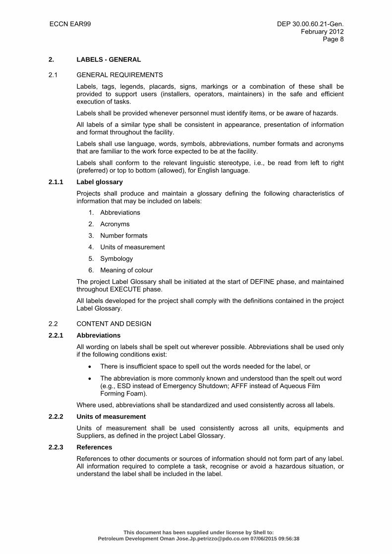
1.3.2 Specific definitions
Term Definition
Caution Label Indicates a potentially hazardous situation, which, if not avoided, may result in minor injury to a person, minor damage to the equipment, or a minor pollution problem. A caution label should not be used when there is a possibility of death or serious injury.
Danger Label Indicates a hazardous situation, which, if not avoided, could result in death or serious injury to a person, serious damage to vital equipment, or a major environmental pollution problem.
Hazard Label A type of label used to identify and provide information about situations that may be hazardous to personnel, equipment or the environment. The types of labels to be used are "DANGER" and "CAUTION".
Identification Label
A type of label used to identify piping contents, vessel contents, and individual equipment, (e.g., valves, gauges, junction boxes, filters, pumps, transmitters, controls), or places (e.g., rooms, buildings, etc.).
Information Label
A type of label used to present non-procedural information of a general nature.
Independent Symbols
Symbols that alone provide information to the user without requiring elaboration by supporting text (e.g., earmuffs to indicate a high noise area requiring hearing protection).
Instruction Label
A type of label used to present instructions for accomplishing a specific task or tasks, along with any hazard or safety information related to performing the task(s).
Label Any plate, sign, placard, inscription, legend, symbol, marking or combination thereof, which is used to impart visual information, warnings or instructions to a reader.
Label Catalogue A list of all labels placed in a facility, such that persons at the facility could use the list to purchase, or have made, the same label if the original labels required replacement or additional labels of a particular type were needed at the facility.
Marking Painted (e.g., stencilled) information that conveys visual information, warnings or instructions to a reader.
This document has been supplied under license by Shell to:Petroleum Development Oman [email protected] 07/06/2015 09:56:38
ECCN EAR99 DEP 30.00.60.21-Gen. February 2012
Page 7
Notice Signs used to indicate a statement of company policy directly or indirectly related to the safety of personnel or protection of property. This signal word should not be associated directly with a hazard or hazardous situation and shall not be used in place of “DANGER” or “CAUTION.”
Panel and Console Labels
Labels that appear on operator consoles and panels to identify individual or groups of controls or displays.
Sign See “Label”.
Tag Physical plate, sign or placard that is attached to an item by lanyard, chain or similar, and contains visual information for the reader.
Tag Number Unique alphanumeric identifier used to identify assets or an equipment item (valve, instrument, vessel, pipeline, etc.).
1.3.3 Abbreviations
Term Definition
ANSI American National Standard
API American Petroleum Institute
ASME American Society of Mechanical Engineers
ISO International Organization for Standardization
P&ID Piping and Instrumentation Diagram
UV Ultra-violet
1.4 CROSS-REFERENCES
Where cross-references to other parts of this DEP are made, the referenced section number is shown in brackets ( ). Other documents referenced by this DEP are listed in (12).
1.5 COMMENTS ON THIS DEP
Comments on this DEP may be sent to the Administrator at [email protected], using the DEP Feedback Form. The DEP Feedback Form can be found on the main page of “DEPs on the Web”, available through the Global Technical Standards web portal http://sww.shell.com/standards and on the main page of the DEPs DVD-ROM.
1.6 DUAL UNITS
This DEP contains both the International System (SI) units, as well as the corresponding US Customary (USC) units, which are given following the SI units in brackets. When agreed by the Principal, the indicated USC values/units may be used.
This document has been supplied under license by Shell to:Petroleum Development Oman [email protected] 07/06/2015 09:56:38
ECCN EAR99 DEP 30.00.60.21-Gen. February 2012
Page 8
2. LABELS - GENERAL
2.1 GENERAL REQUIREMENTS
Labels, tags, legends, placards, signs, markings or a combination of these shall be provided to support users (installers, operators, maintainers) in the safe and efficient execution of tasks.
Labels shall be provided whenever personnel must identify items, or be aware of hazards.
All labels of a similar type shall be consistent in appearance, presentation of information and format throughout the facility.
Labels shall use language, words, symbols, abbreviations, number formats and acronyms that are familiar to the work force expected to be at the facility.
Labels shall conform to the relevant linguistic stereotype, i.e., be read from left to right (preferred) or top to bottom (allowed), for English language.
2.1.1 Label glossary
Projects shall produce and maintain a glossary defining the following characteristics of information that may be included on labels:
1. Abbreviations
2. Acronyms
3. Number formats
4. Units of measurement
5. Symbology
6. Meaning of colour
The project Label Glossary shall be initiated at the start of DEFINE phase, and maintained throughout EXECUTE phase.
All labels developed for the project shall comply with the definitions contained in the project Label Glossary.
2.2 CONTENT AND DESIGN
2.2.1 Abbreviations
All wording on labels shall be spelt out wherever possible. Abbreviations shall be used only if the following conditions exist:
• There is insufficient space to spell out the words needed for the label, or
• The abbreviation is more commonly known and understood than the spelt out word (e.g., ESD instead of Emergency Shutdown; AFFF instead of Aqueous Film Forming Foam).
Where used, abbreviations shall be standardized and used consistently across all labels.
2.2.2 Units of measurement
Units of measurement shall be used consistently across all units, equipments and Suppliers, as defined in the project Label Glossary.
2.2.3 References
References to other documents or sources of information should not form part of any label. All information required to complete a task, recognise or avoid a hazardous situation, or understand the label shall be included in the label.
This document has been supplied under license by Shell to:Petroleum Development Oman [email protected] 07/06/2015 09:56:38
ECCN EAR99 DEP 30.00.60.21-Gen. February 2012
Page 9
2.2.4 Irrelevant information
Information not directly required by the user to accomplish the operational tasks (e.g., trade names and company logos), should be avoided on the face of the following:
1. Consoles;
2. Control panels;
3. Displays;
4. Any other location in direct line of sight of the user.
Non-task oriented information should be placed on the side or back of the display or console when viewed from the expected working position.
2.2.5 Characters to avoid
Characters, letters and symbols which are highly confusable should not be used in combinations or situations where incorrect reading could lead to a significant misunderstanding. For example, when labels are in English, the number “1” should not be used in combination with the letters “L” or “I”, and the number “0” should not be used in combination with the letters “O” or “Q”.
2.2.6 Character and numerals
Characters shall be simple block type format, using a font such as Arial or Helvetica. Numerals shall be Arabic (as opposed to Roman).
2.2.7 Character and background colour
Vessel, equipment, component, instrument device and cable identification labels shall be provided with black characters on a white background.
2.2.8 Surface colour contrast
Label background colour shall contrast with the colour of the surface to which the label will be attached. Safety colour specification should follow ANSI Z535.1 or ISO 3864-4 as appropriate unless compliance with an equivalent local national or regulatory standard is required.
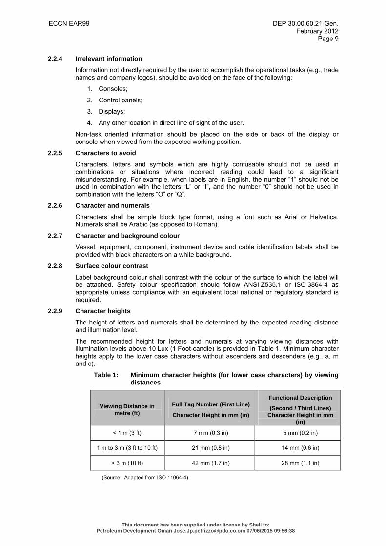
2.2.9 Character heights
The height of letters and numerals shall be determined by the expected reading distance and illumination level.
The recommended height for letters and numerals at varying viewing distances with illumination levels above 10 Lux (1 Foot-candle) is provided in Table 1. Minimum character heights apply to the lower case characters without ascenders and descenders (e.g., a, m and c).
Table 1: Minimum character heights (for lower case characters) by viewing distances
Viewing Distance in metre (ft)
Full Tag Number (First Line)
Character Height in mm (in)
Functional Description
(Second / Third Lines) Character Height in mm
(in)
< 1 m (3 ft) 7 mm (0.3 in) 5 mm (0.2 in)
1 m to 3 m (3 ft to 10 ft) 21 mm (0.8 in) 14 mm (0.6 in)
> 3 m (10 ft) 42 mm (1.7 in) 28 mm (1.1 in)
(Source: Adapted from ISO 11064-4)
This document has been supplied under license by Shell to:Petroleum Development Oman [email protected] 07/06/2015 09:56:38
ECCN EAR99 DEP 30.00.60.21-Gen. February 2012
Page 10
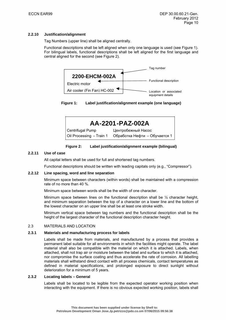
2.2.10 Justification/alignment
Tag Numbers (upper line) shall be aligned centrally.
Functional descriptions shall be left aligned when only one language is used (see Figure 1). For bilingual labels, functional descriptions shall be left aligned for the first language and central aligned for the second (see Figure 2).
Figure 1: Label justification/alignment example (one language)
Figure 2: Label justification/alignment example (bilingual)
2.2.11 Use of case
All capital letters shall be used for full and shortened tag numbers.
Functional descriptions should be written with leading capitals only (e.g., “Compressor”).
2.2.12 Line spacing, word and line separation
Minimum space between characters (within words) shall be maintained with a compression rate of no more than 40 %.
Minimum space between words shall be the width of one character.
Minimum space between lines on the functional description shall be ½ character height, and minimum separation between the top of a character on a lower line and the bottom of the lowest character on an upper line shall be at least one stroke width.
Minimum vertical space between tag numbers and the functional description shall be the height of the largest character of the functional description character height.
2.3 MATERIALS AND LOCATION
2.3.1 Materials and manufacturing process for labels
Labels shall be made from materials, and manufactured by a process that provides a permanent label suitable for all environments in which the facilities might operate. The label material shall also be compatible with the material on which it is attached. Labels, when attached, shall not trap air or moisture between the label and surface to which it is attached, nor compromise the surface coating and thus accelerate the rate of corrosion. All labelling materials shall withstand direct contact with all process chemicals, contact temperatures as defined in material specifications, and prolonged exposure to direct sunlight without deterioration for a minimum of 5 years.
2.3.2 Locating labels – General
Labels shall be located to be legible from the expected operator working position when interacting with the equipment. If there is no obvious expected working position, labels shall
AA-2201-PAZ-002ACentrifugal Pump Oil Processing – Train 1
Центробежный Насос Обработка Нефти – Обучается 1
2200-EHCM-002A Electric motor
Air cooler (Fin Fan) HC-002
Tag number
Functional description
Location or associatedequipment details
This document has been supplied under license by Shell to:Petroleum Development Oman [email protected] 07/06/2015 09:56:38
ECCN EAR99 DEP 30.00.60.21-Gen. February 2012
Page 11
be visible from a position intended for operator access, and without exposing operators to risk of injury or exposure to hazards.
The location of labels shall provide a simple, direct and unambiguous spatial relationship with the equipment or item referred to (i.e., the location of the label shall avoid the potential for ambiguity about which physical item it refers to). Identification labels shall be mounted on, or immediately adjacent to, the component so that the label is immediately visually obvious which component goes with which label.
Labels shall be located so as not to be covered by movable items such as doors, racks, access openings or equipment that may be moved in and out of a space, or temporarily stored there. Where a unit or skid-based package contains multiple items of the same equipment type (e.g., ‘A’ and ‘B’ pumps, each piece of equipment shall be identified accordingly with the unique equipment number as indicated on the PEFs (P&IDs).
2.3.3 Locating labels – Mounting surface and viewing angle
Labels shall be located on flat surfaces. If a curved surface is used, all of the information contained on the label shall be visible to the reader from the expected working position, or another mode of labelling shall be used (e.g., phenolic label or an etched stainless steel plate attached with a chain or wire).
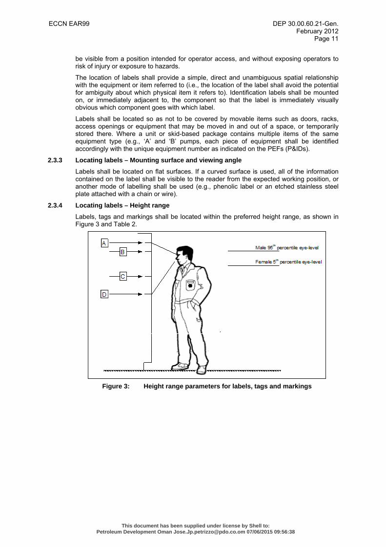
2.3.4 Locating labels – Height range
Labels, tags and markings shall be located within the preferred height range, as shown in Figure 3 and Table 2.
Figure 3: Height range parameters for labels, tags and markings
This document has been supplied under license by Shell to:Petroleum Development Oman [email protected] 07/06/2015 09:56:38
ECCN EAR99 DEP 30.00.60.21-Gen. February 2012
Page 12
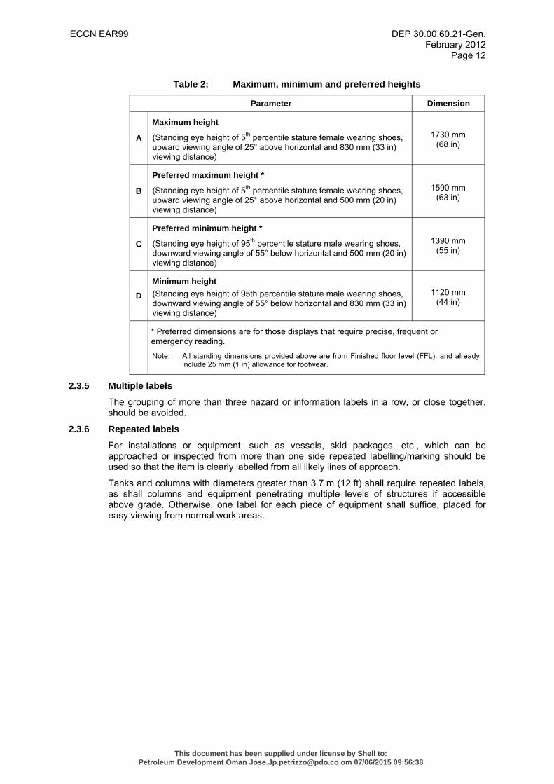
Table 2: Maximum, minimum and preferred heights
Parameter Dimension
A
Maximum height
(Standing eye height of 5th percentile stature female wearing shoes, upward viewing angle of 25° above horizontal and 830 mm (33 in) viewing distance)
1730 mm (68 in)
B
Preferred maximum height *
(Standing eye height of 5th percentile stature female wearing shoes, upward viewing angle of 25° above horizontal and 500 mm (20 in) viewing distance)
1590 mm (63 in)
C
Preferred minimum height *
(Standing eye height of 95th percentile stature male wearing shoes, downward viewing angle of 55° below horizontal and 500 mm (20 in) viewing distance)
1390 mm (55 in)
D Minimum height (Standing eye height of 95th percentile stature male wearing shoes, downward viewing angle of 55° below horizontal and 830 mm (33 in) viewing distance)
1120 mm (44 in)
* Preferred dimensions are for those displays that require precise, frequent or emergency reading.
Note: All standing dimensions provided above are from Finished floor level (FFL), and already include 25 mm (1 in) allowance for footwear.
2.3.5 Multiple labels
The grouping of more than three hazard or information labels in a row, or close together, should be avoided.
2.3.6 Repeated labels
For installations or equipment, such as vessels, skid packages, etc., which can be approached or inspected from more than one side repeated labelling/marking should be used so that the item is clearly labelled from all likely lines of approach.
Tanks and columns with diameters greater than 3.7 m (12 ft) shall require repeated labels, as shall columns and equipment penetrating multiple levels of structures if accessible above grade. Otherwise, one label for each piece of equipment shall suffice, placed for easy viewing from normal work areas.
This document has been supplied under license by Shell to:Petroleum Development Oman [email protected] 07/06/2015 09:56:38
ECCN EAR99 DEP 30.00.60.21-Gen. February 2012
Page 13
3. EQUIPMENT AND COMPONENT IDENTIFICATION LABELS
3.1 SPECIFIC REQUIREMENTS
Identification labels shall be placed on all equipment and components requiring physical manipulation for operations or maintenance. Equipment and components include, but are not limited to the following:
• Equipment (e.g., vessels, pumps, filters, electrical and communications, etc.)
• Instrument devices (e.g., gauges, transmitters, etc.)
• Valves (actuated control valves)
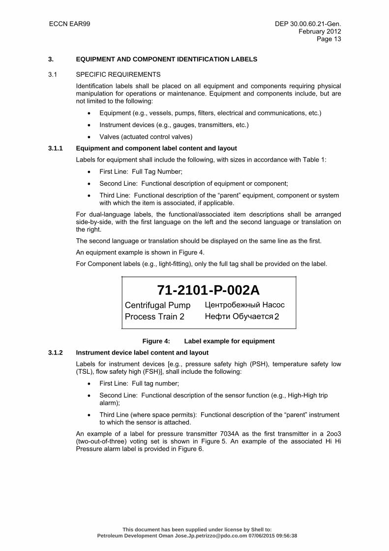
3.1.1 Equipment and component label content and layout
Labels for equipment shall include the following, with sizes in accordance with Table 1:
• First Line: Full Tag Number;
• Second Line: Functional description of equipment or component;
• Third Line: Functional description of the “parent” equipment, component or system with which the item is associated, if applicable.
For dual-language labels, the functional/associated item descriptions shall be arranged side-by-side, with the first language on the left and the second language or translation on the right.
The second language or translation should be displayed on the same line as the first.
An equipment example is shown in Figure 4.
For Component labels (e.g., light-fitting), only the full tag shall be provided on the label.
Figure 4: Label example for equipment
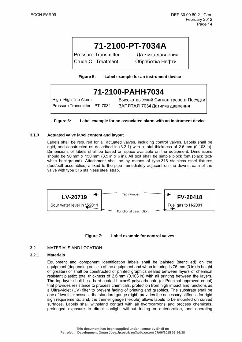
3.1.2 Instrument device label content and layout
Labels for instrument devices [e.g., pressure safety high (PSH), temperature safety low (TSL), flow safety high (FSH)], shall include the following:
• First Line: Full tag number;
• Second Line: Functional description of the sensor function (e.g., High-High trip alarm);
• Third Line (where space permits): Functional description of the “parent” instrument to which the sensor is attached.
An example of a label for pressure transmitter 7034A as the first transmitter in a 2oo3 (two-out-of-three) voting set is shown in Figure 5. An example of the associated Hi Hi Pressure alarm label is provided in Figure 6.
71-2101-P-002ACentrifugal PumpProcess Train 2
Центробежный Насос Нефти Обучается2
This document has been supplied under license by Shell to:Petroleum Development Oman [email protected] 07/06/2015 09:56:38
ECCN EAR99 DEP 30.00.60.21-Gen. February 2012
Page 14
Figure 5: Label example for an instrument device
Figure 6: Label example for an associated alarm with an instrument device
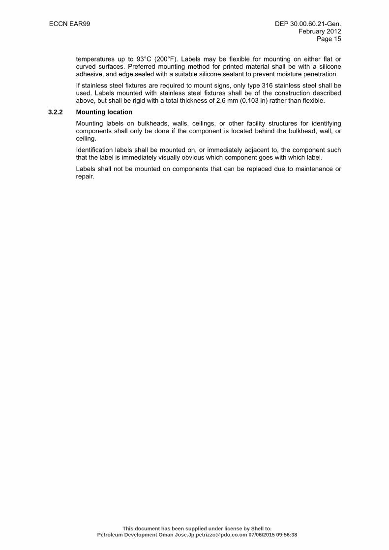
3.1.3 Actuated valve label content and layout
Labels shall be required for all actuated valves, including control valves. Labels shall be rigid, and constructed as described in (3.2.1) with a total thickness of 2.6 mm (0.103 in). Dimensions of labels shall be based on space available on the equipment. Dimensions should be 90 mm x 150 mm (3.5 in x 6 in). All text shall be simple block font (black text/ white background). Attachment shall be by means of type 316 stainless steel fixtures (foot/bolt assemblies) affixed to the pipe immediately adjacent on the downstream of the valve with type 316 stainless steel strap.
Figure 7: Label example for control valves
3.2 MATERIALS AND LOCATION
3.2.1 Materials
Equipment and component identification labels shall be painted (stencilled) on the equipment (depending on size of the equipment and when lettering is 75 mm (3 in) in height or greater) or shall be constructed of printed graphics sealed between layers of chemical resistant plastic; total thickness of 2.6 mm (0.103 in) with all printing between the layers. The top layer shall be a hard-coated Lexan® polycarbonate (or Principal approved equal) that provides resistance to process chemicals, protection from high impact and functions as a Ultra-violet (UV) filter to prevent fading of printing and graphics. The substrate shall be one of two thicknesses: the standard gauge (rigid) provides the necessary stiffness for rigid sign requirements; and, the thinner gauge (flexible) allows labels to be mounted on curved surfaces. Labels shall withstand contact with all hydrocarbons and process chemicals, prolonged exposure to direct sunlight without fading or deterioration, and operating
71-2100-PT-7034APressure TransmitterCrude Oil Treatment
Датчика давления Обработка Нефти
71-2100-PAHH-7034High -High Trip AlarmPressure Transmitter PT-7034
Высоко -высокий Сигнал тревоги ПоездкиЗАПЯТАЯ-7034Датчика давления
LV-20719 Sour water level in V-2011
FV-20418 Fuel gas to H-2001
Tag number
Functional description
This document has been supplied under license by Shell to:Petroleum Development Oman [email protected] 07/06/2015 09:56:38
ECCN EAR99 DEP 30.00.60.21-Gen. February 2012
Page 15
temperatures up to 93°C (200°F). Labels may be flexible for mounting on either flat or curved surfaces. Preferred mounting method for printed material shall be with a silicone adhesive, and edge sealed with a suitable silicone sealant to prevent moisture penetration.
If stainless steel fixtures are required to mount signs, only type 316 stainless steel shall be used. Labels mounted with stainless steel fixtures shall be of the construction described above, but shall be rigid with a total thickness of 2.6 mm (0.103 in) rather than flexible.
3.2.2 Mounting location
Mounting labels on bulkheads, walls, ceilings, or other facility structures for identifying components shall only be done if the component is located behind the bulkhead, wall, or ceiling.
Identification labels shall be mounted on, or immediately adjacent to, the component such that the label is immediately visually obvious which component goes with which label.
Labels shall not be mounted on components that can be replaced due to maintenance or repair.
This document has been supplied under license by Shell to:Petroleum Development Oman [email protected] 07/06/2015 09:56:38
ECCN EAR99 DEP 30.00.60.21-Gen. February 2012
Page 16
4. CABLE IDENTIFICATION LABELS
4.1 GENERAL REQUIREMENTS
Cable identification labels or markers shall be placed on all cables. Cables to be identified include but are not limited to those associated with:
1. Instruments;
2. Communications equipment;
3. Electrical;
4. Fire & Gas equipment;
5. Lighting and small power devices.
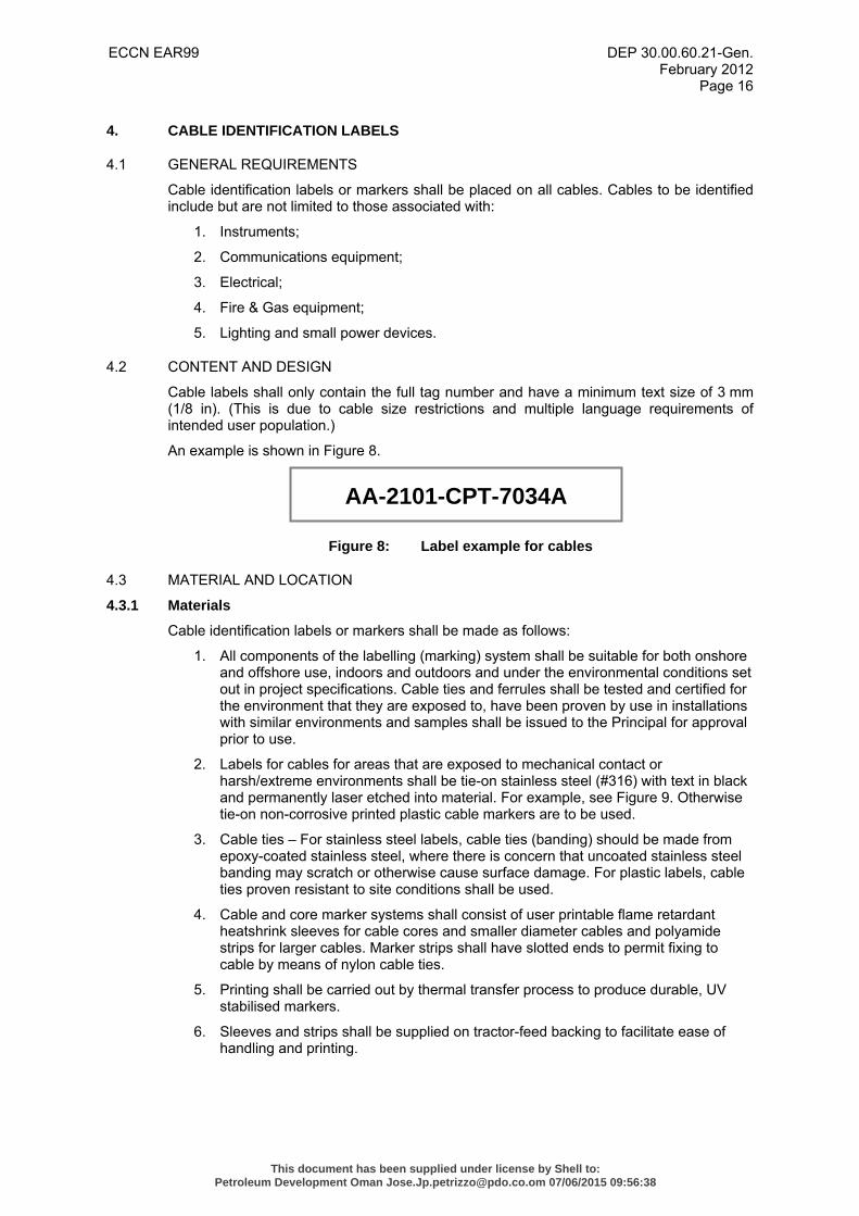
4.2 CONTENT AND DESIGN
Cable labels shall only contain the full tag number and have a minimum text size of 3 mm (1/8 in). (This is due to cable size restrictions and multiple language requirements of intended user population.)
An example is shown in Figure 8.
Figure 8: Label example for cables
4.3 MATERIAL AND LOCATION
4.3.1 Materials
Cable identification labels or markers shall be made as follows:
1. All components of the labelling (marking) system shall be suitable for both onshore and offshore use, indoors and outdoors and under the environmental conditions set out in project specifications. Cable ties and ferrules shall be tested and certified for the environment that they are exposed to, have been proven by use in installations with similar environments and samples shall be issued to the Principal for approval prior to use.
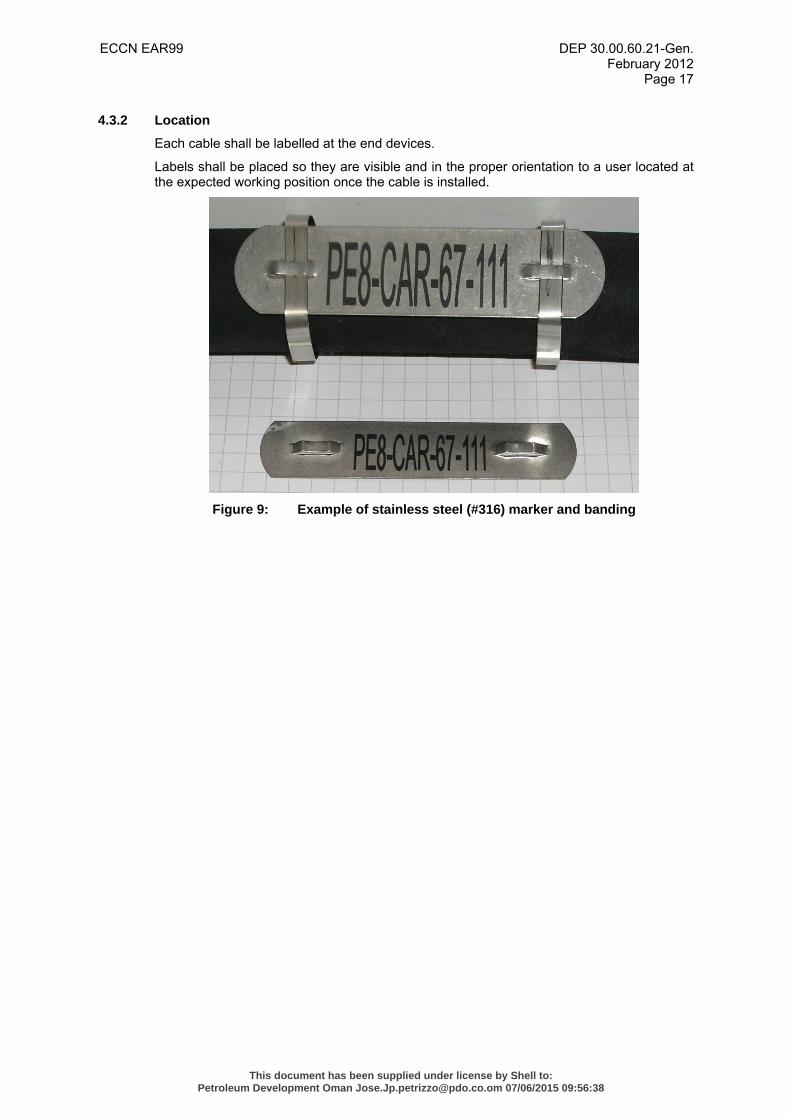
2. Labels for cables for areas that are exposed to mechanical contact or harsh/extreme environments shall be tie-on stainless steel (#316) with text in black and permanently laser etched into material. For example, see Figure 9. Otherwise tie-on non-corrosive printed plastic cable markers are to be used.
3. Cable ties – For stainless steel labels, cable ties (banding) should be made from epoxy-coated stainless steel, where there is concern that uncoated stainless steel banding may scratch or otherwise cause surface damage. For plastic labels, cable ties proven resistant to site conditions shall be used.
4. Cable and core marker systems shall consist of user printable flame retardant heatshrink sleeves for cable cores and smaller diameter cables and polyamide strips for larger cables. Marker strips shall have slotted ends to permit fixing to cable by means of nylon cable ties.
5. Printing shall be carried out by thermal transfer process to produce durable, UV stabilised markers.
6. Sleeves and strips shall be supplied on tractor-feed backing to facilitate ease of handling and printing.
AA-2101-CPT-7034A
This document has been supplied under license by Shell to:Petroleum Development Oman [email protected] 07/06/2015 09:56:38
ECCN EAR99 DEP 30.00.60.21-Gen. February 2012
Page 17
4.3.2 Location
Each cable shall be labelled at the end devices.
Labels shall be placed so they are visible and in the proper orientation to a user located at the expected working position once the cable is installed.
Figure 9: Example of stainless steel (#316) marker and banding
This document has been supplied under license by Shell to:Petroleum Development Oman [email protected] 07/06/2015 09:56:38
ECCN EAR99 DEP 30.00.60.21-Gen. February 2012
Page 18
5. PANEL AND CONSOLE LABELS
5.1 GENERAL REQUIREMENTS
Panel and consoles, including individual displays and controls and associated setting positions shall be labelled in accordance with the requirements of this section.
5.2 CONTENT AND DESIGN
5.2.1 Language/translation
The first translation shall be displayed at the top with the second and, if absolutely necessary, the third following below and text shall be aligned centrally with line spacing, word and line separation as per (2). All upper case letters shall be used.
5.2.2 What is being measured or controlled?
Controls and displays shall be labelled in terms of what is being measured or controlled, not what the control or display is (e.g., write VOLTAGE rather than VOLTMETER; POWER ADJUST rather than POWER ADJUSTER SWITCH).
5.2.3 Control labelling
Control labelling shall indicate the functional result of a control movement (e.g., INCREASE, ON, OFF, START, DIM).
5.2.4 Consistency
Terminology for the same controls and displays used on different equipment or systems shall be the same.
5.2.5 Units of measure
Units of measure (e.g., psig, volts, kPa and mm) shall appear on the face of displays, not on the labels.
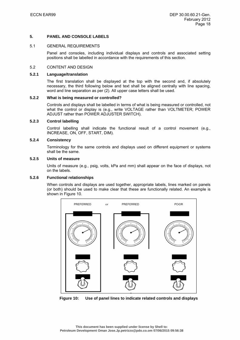
5.2.6 Functional relationships
When controls and displays are used together, appropriate labels, lines marked on panels (or both) should be used to make clear that these are functionally related. An example is shown in Figure 10.
Figure 10: Use of panel lines to indicate related controls and displays
This document has been supplied under license by Shell to:Petroleum Development Oman [email protected] 07/06/2015 09:56:38
ECCN EAR99 DEP 30.00.60.21-Gen. February 2012
Page 19
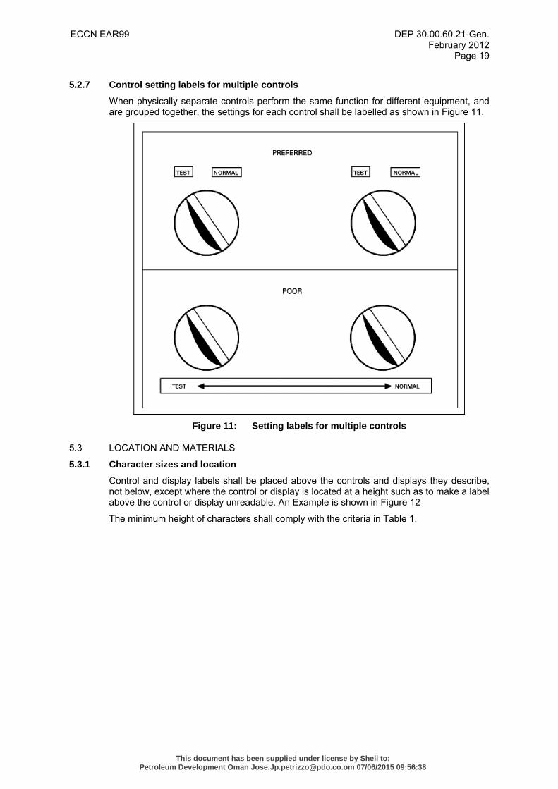
5.2.7 Control setting labels for multiple controls
When physically separate controls perform the same function for different equipment, and are grouped together, the settings for each control shall be labelled as shown in Figure 11.
Figure 11: Setting labels for multiple controls
5.3 LOCATION AND MATERIALS
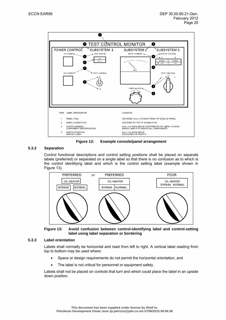
5.3.1 Character sizes and location
Control and display labels shall be placed above the controls and displays they describe, not below, except where the control or display is located at a height such as to make a label above the control or display unreadable. An Example is shown in Figure 12
The minimum height of characters shall comply with the criteria in Table 1.
This document has been supplied under license by Shell to:Petroleum Development Oman [email protected] 07/06/2015 09:56:38
ECCN EAR99 DEP 30.00.60.21-Gen. February 2012
Page 20
1
Figure 12: Example console/panel arrangement
5.3.2 Separation
Control functional descriptions and control setting positions shall be placed on separate labels (preferred) or separated on a single label so that there is no confusion as to which is the control identifying label and which is the control setting label (example shown in Figure 13).
Figure 13: Avoid confusion between control-identifying label and control-setting
label using label separation or bordering
5.3.3 Label orientation
Labels shall normally be horizontal and read from left to right. A vertical label reading from top to bottom may be used where:
• Space or design requirements do not permit the horizontal orientation, and
• The label is not critical for personnel or equipment safety.
Labels shall not be placed on controls that turn and which could place the label in an upside down position.
This document has been supplied under license by Shell to:Petroleum Development Oman [email protected] 07/06/2015 09:56:38
ECCN EAR99 DEP 30.00.60.21-Gen. February 2012
Page 21
5.3.4 Material choice
Panel and console labels should be made of either engraved plastic, reverse Lexan® or UV-protected flexible vinyl and shall be suitable for the environmental conditions.
5.3.5 Installation
Labels shall be attached with stainless-steel screws or of the same material of the item being labelled to prevent dissimilar metal corrosion.
This document has been supplied under license by Shell to:Petroleum Development Oman [email protected] 07/06/2015 09:56:38
ECCN EAR99 DEP 30.00.60.21-Gen. February 2012
Page 22
6. PIPE MARKERS
6.1 GENERAL COLOUR-CODING REQUIREMENTS
Selected piping systems of 20 mm (3/4 in) or greater in outside diameter shall be marked with colour-coded pipe markers, as follows:
1. All pipes carrying hydrocarbon liquids and gas;
2. Fire-fighting mediums;
3. High-pressure gases (Air or Nitrogen) or liquids;
4. Chemicals, potable water;
5. Non-potable water;
6. Seawater; and
7. Pipes carrying toxic or sanitary wastes.
The markers shall contain labelling to identify the following:
1. Pipe content;
2. Direction of flow of the pipe contents;
3. Where it is deemed of value to identify where the pipe content is coming from, and/or going to, a pipe “to/from” label may be incorporated into the pipe marker.
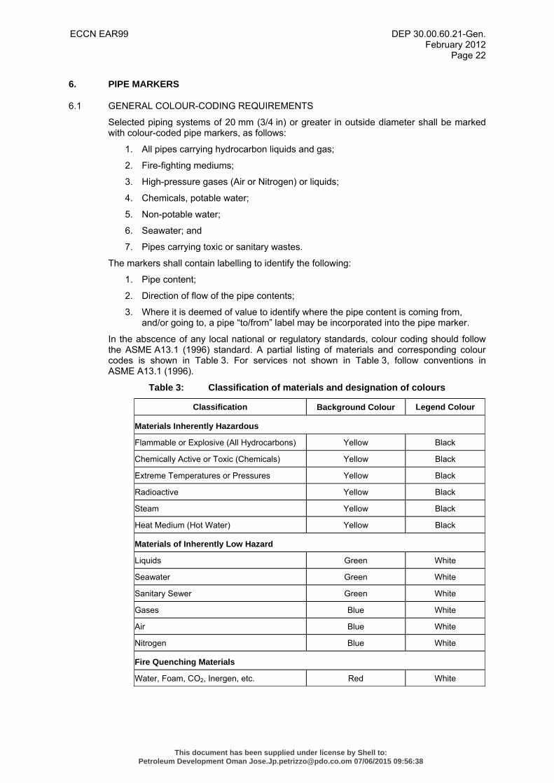
In the abscence of any local national or regulatory standards, colour coding should follow the ASME A13.1 (1996) standard. A partial listing of materials and corresponding colour codes is shown in Table 3. For services not shown in Table 3, follow conventions in ASME A13.1 (1996).
Table 3: Classification of materials and designation of colours
Classification Background Colour Legend Colour
Materials Inherently Hazardous
Flammable or Explosive (All Hydrocarbons) Yellow Black
Chemically Active or Toxic (Chemicals) Yellow Black
Extreme Temperatures or Pressures Yellow Black
Radioactive Yellow Black
Steam Yellow Black
Heat Medium (Hot Water) Yellow Black
Materials of Inherently Low Hazard
Liquids Green White
Seawater Green White
Sanitary Sewer Green White
Gases Blue White
Air Blue White
Nitrogen Blue White
Fire Quenching Materials
Water, Foam, CO2, Inergen, etc. Red White
This document has been supplied under license by Shell to:Petroleum Development Oman [email protected] 07/06/2015 09:56:38
ECCN EAR99 DEP 30.00.60.21-Gen. February 2012
Page 23
6.2 METHOD OF IDENTIFICATION
Positive identification of the contents of a piping system shall be by line label (lettered legend) giving the name of the contents in full or abbreviated form as illustrated below:
• HEAT MEDIUM • HP NITROGEN • DEFOAMER • IP GAS • GLYCOL • STEAM • HP DRY OIL • FIRE WATER • INSTRUMENT AIR • UTILITY SEA WATER • SANITARY SEWER DRAIN • POTABLE WATER • FWKO GAS TO FGC • HP OIL TO IP SEPARATOR
Contents shall be identified by lettered legend with sufficient additional details such as temperature, pressure, etc., as are necessary to identify the hazard.
The lettered legend shall be brief, informative, pointed and simple for greatest effectiveness.
The “to/from” labels or stenciling design characteristics shall be determined by the following:
• Amount of wording to be used, and
• Reading distance required
Arrows shall be used to indicate direction of flow.
Flow arrows and legends shall repeat around the circumference in such a way as to be legible from all viewing positions.
Colour should be used to identify the characteristic hazards of the contents (see Table 3). Colour should be displayed on or contiguous to, the piping by any physical means, but its use shall be in combination with a legend.
Adequate contrast shall be provided between background colour and the legend to ensure readability under expected lighting conditions. Refer to Table 3 for specific colour and line label (legend) recommendations.
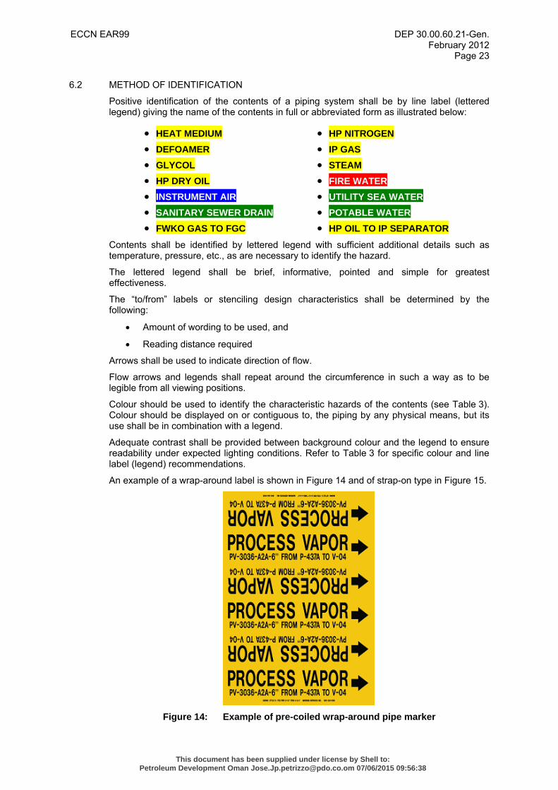
An example of a wrap-around label is shown in Figure 14 and of strap-on type in Figure 15.
Figure 14: Example of pre-coiled wrap-around pipe marker
This document has been supplied under license by Shell to:Petroleum Development Oman [email protected] 07/06/2015 09:56:38
ECCN EAR99 DEP 30.00.60.21-Gen. February 2012
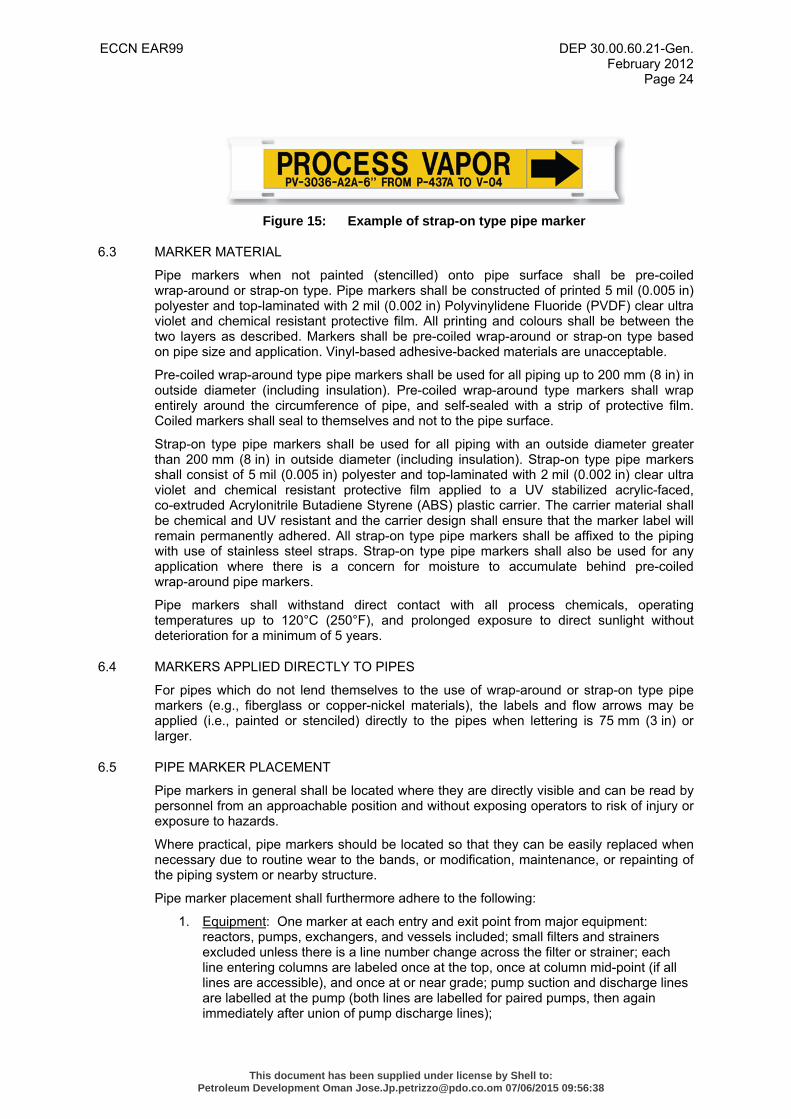
Page 24
Figure 15: Example of strap-on type pipe marker
6.3 MARKER MATERIAL
Pipe markers when not painted (stencilled) onto pipe surface shall be pre-coiled wrap-around or strap-on type. Pipe markers shall be constructed of printed 5 mil (0.005 in) polyester and top-laminated with 2 mil (0.002 in) Polyvinylidene Fluoride (PVDF) clear ultra violet and chemical resistant protective film. All printing and colours shall be between the two layers as described. Markers shall be pre-coiled wrap-around or strap-on type based on pipe size and application. Vinyl-based adhesive-backed materials are unacceptable.
Pre-coiled wrap-around type pipe markers shall be used for all piping up to 200 mm (8 in) in outside diameter (including insulation). Pre-coiled wrap-around type markers shall wrap entirely around the circumference of pipe, and self-sealed with a strip of protective film. Coiled markers shall seal to themselves and not to the pipe surface.
Strap-on type pipe markers shall be used for all piping with an outside diameter greater than 200 mm (8 in) in outside diameter (including insulation). Strap-on type pipe markers shall consist of 5 mil (0.005 in) polyester and top-laminated with 2 mil (0.002 in) clear ultra violet and chemical resistant protective film applied to a UV stabilized acrylic-faced, co-extruded Acrylonitrile Butadiene Styrene (ABS) plastic carrier. The carrier material shall be chemical and UV resistant and the carrier design shall ensure that the marker label will remain permanently adhered. All strap-on type pipe markers shall be affixed to the piping with use of stainless steel straps. Strap-on type pipe markers shall also be used for any application where there is a concern for moisture to accumulate behind pre-coiled wrap-around pipe markers.
Pipe markers shall withstand direct contact with all process chemicals, operating temperatures up to 120°C (250°F), and prolonged exposure to direct sunlight without deterioration for a minimum of 5 years.
6.4 MARKERS APPLIED DIRECTLY TO PIPES
For pipes which do not lend themselves to the use of wrap-around or strap-on type pipe markers (e.g., fiberglass or copper-nickel materials), the labels and flow arrows may be applied (i.e., painted or stenciled) directly to the pipes when lettering is 75 mm (3 in) or larger.
6.5 PIPE MARKER PLACEMENT
Pipe markers in general shall be located where they are directly visible and can be read by personnel from an approachable position and without exposing operators to risk of injury or exposure to hazards.
Where practical, pipe markers should be located so that they can be easily replaced when necessary due to routine wear to the bands, or modification, maintenance, or repainting of the piping system or nearby structure.
Pipe marker placement shall furthermore adhere to the following:
1. Equipment: One marker at each entry and exit point from major equipment: reactors, pumps, exchangers, and vessels included; small filters and strainers excluded unless there is a line number change across the filter or strainer; each line entering columns are labeled once at the top, once at column mid-point (if all lines are accessible), and once at or near grade; pump suction and discharge lines are labelled at the pump (both lines are labelled for paired pumps, then again immediately after union of pump discharge lines);
This document has been supplied under license by Shell to:Petroleum Development Oman [email protected] 07/06/2015 09:56:38
ECCN EAR99 DEP 30.00.60.21-Gen. February 2012
Page 25
2. Manifolds: A marker shall be placed immediately adjacent to each valve in a manifold and immediately adjacent to every block valve used to isolate piping systems or major equipment, in clear view from the position required to operate the valves;
3. Utility Stations: All lines at utility stations shall be labeled once immediately adjacent to hook-up point;
4. Control Valves: Once on the downstream pipe adjacent to the valve; vertical lines to/from control valves shall each be labeled only where specific valves have lines entering and exiting the valve in a continuous loop;
5. Solid Wall Penetrations: Once on each side of all solid wall, bulkhead, floor or ceiling thru-penetrations, within 1.5 m (5 ft) of penetration. except where a single marker is readily visible from both sides of a penetration, in which case only one marker is needed;
6. Vertical Piping: Once on vertical pass-thru piping on each level of multi-level structures, placed at placed approximately 1.8 m (6 ft) above the walking surface level;
7. Horizontal Piping: Horizontal lines are labelled every 10 m (30 ft);
8. Pipe Racks: Rack piping shall be labelled at approximately 15 m to 30 m (50 ft to 100 ft) intervals, and within 6 m (20 ft) of major pipe rack intersections. Where pipe markers are required on two or more pipes in a group of pipes located side-by-side (e.g., in a pipe rack), all of the pipe markers shall be installed side-by-side so they can be easily scanned at one time. This provides a uniform appearance and consistent visibility for all connecting pipe;
9. Branches from pipe racks: Branches are labeled at the connection, and every 10 m (30 ft) thereafter until connection with equipment;
10. Vendor Skids: Once for each line entering and exiting Vendor-furnished skids as depicted on P&IDs, unless drawings for Vendor-furnished skids (and linear footage of piping) have been provided with specific direction to label lines internal to skids.
When more than one of the criteria described above occurs on the same pipe in a general area within 4.5 m (15 ft), then a single marker will suffice to identify the pipe.
This document has been supplied under license by Shell to:Petroleum Development Oman [email protected] 07/06/2015 09:56:38
ECCN EAR99 DEP 30.00.60.21-Gen. February 2012
Page 26
7. HAZARD IDENTIFICATION LABELS
7.1 HAZARD LEVEL SELECTION CRITERIA
There shall be only two (2) levels of hazard labels in the facility as follows:
“DANGER” and “CAUTION”
The levels shall be based on the potential effect of hazards to personnel as well as potential effects to property or the environment.
The decision as to which level to use shall be based on the definitions provided in the definitions section of this DEP.
7.2 FORMAT
Unless there is a local national or regulatory standard that takes precedence, hazard identification labels shall comply with requirements of ANSI Z535.2 and shall contain the following information:
1. A signal word (DANGER or CAUTION) at the top of the label;
2. A Safety Alert Symbol (i.e., equilateral triangle surrounding an exclamation mark) if there is a potential personal injury hazard;
3. A specific, brief statement of the hazard (e.g., 600 Volts AC, not HIGH VOLTAGE);
4. A pictorial symbol showing the hazard, if available;
5. Brief detail on how to avoid the hazard; if more than one action is involved, instructions shall be provided in step-by-step sequence (e.g., “Stay clear of this area” or “Disconnect all power sources before removing the panel”); and
6. A brief statement of the possible consequences if the instructions given are not followed (e.g., “serious injury could occur”, “fire or explosion could occur”, “death could result”).
Signal word format and size as well as the height of the inscription or message text shall be based on the minimum safe viewing distance as outlined in ANSI Z535.2.
Message text, other than the signal word header, on a hazard identification sign shall use leading capitals.
Black characters on a white background shall be used as illustrated in Figures 13 and 4.
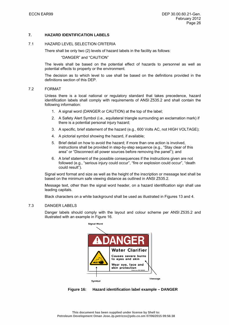
7.3 DANGER LABELS
Danger labels should comply with the layout and colour scheme per ANSI Z535.2 and illustrated with an example in Figure 16.
Figure 16: Hazard identification label example – DANGER
This document has been supplied under license by Shell to:Petroleum Development Oman [email protected] 07/06/2015 09:56:38
ECCN EAR99 DEP 30.00.60.21-Gen. February 2012
Page 27
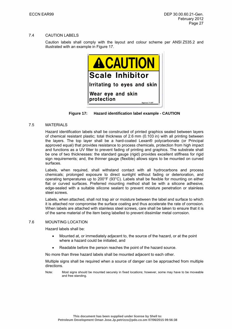
7.4 CAUTION LABELS
Caution labels shall comply with the layout and colour scheme per ANSI Z535.2 and illustrated with an example in Figure 17.
Figure 17: Hazard identification label example - CAUTION
7.5 MATERIALS
Hazard identification labels shall be constructed of printed graphics sealed between layers of chemical resistant plastic; total thickness of 2.6 mm (0.103 in) with all printing between the layers. The top layer shall be a hard-coated Lexan® polycarbonate (or Principal approved equal) that provides resistance to process chemicals, protection from high impact and functions as a UV filter to prevent fading of printing and graphics. The substrate shall be one of two thicknesses: the standard gauge (rigid) provides excellent stiffness for rigid sign requirements; and, the thinner gauge (flexible) allows signs to be mounted on curved surfaces.
Labels, when required, shall withstand contact with all hydrocarbons and process chemicals; prolonged exposure to direct sunlight without fading or deterioration, and operating temperatures up to 200°F (93°C). Labels shall be flexible for mounting on either flat or curved surfaces. Preferred mounting method shall be with a silicone adhesive, edge-sealed with a suitable silicone sealant to prevent moisture penetration or stainless steel screws.
Labels, when attached, shall not trap air or moisture between the label and surface to which it is attached nor compromise the surface coating and thus accelerate the rate of corrosion. When labels are attached with stainless steel screws, care shall be taken to ensure that it is of the same material of the item being labelled to prevent dissimilar metal corrosion.
7.6 MOUNTING LOCATION
Hazard labels shall be:
• Mounted at, or immediately adjacent to, the source of the hazard, or at the point where a hazard could be initiated, and
• Readable before the person reaches the point of the hazard source.
No more than three hazard labels shall be mounted adjacent to each other.
Multiple signs shall be required when a source of danger can be approached from multiple directions. Note: Most signs should be mounted securely in fixed locations; however, some may have to be moveable
and free standing.
This document has been supplied under license by Shell to:Petroleum Development Oman [email protected] 07/06/2015 09:56:38
ECCN EAR99 DEP 30.00.60.21-Gen. February 2012
Page 28
8. INFORMATION LABELS
8.1 CRITERIA FOR USE
Information labels shall be used only to provide information that will significantly contribute to the employee’s safety or efficiency, and provide information of a general type.
This includes notices of general practice and rules in the following areas:
1. Health
2. First aid
3. Medical equipment
4. Sanitation
5. Housekeeping
6. General safety Note: The signal word (“NOTICE”) should not be associated directly with a hazard or hazardous situation
and shall not be used in place of “DANGER” or “CAUTION.”
8.2 GENERAL
Unless there is a local national or regulatory standard that takes precedence, information labels should comply with requirements of ANSI Z535.2. Information labels should be headed by the signal word “NOTICE”, followed by the necessary information inscription.
8.3 INSCRIPTION
The inscription may be provided in paragraph form if the information does not lend itself well to a step-by-step presentation format. However, if any portion of the information is a list, the inscription shall be presented in list form.
Headings shall be used as appropriate to organize and identify related information.
8.4 LETTER SIZE
The height of the inscription text should be based on ANSI Z535.2 and shall have the following properties:
• The signal word “NOTICE” should be at least 50 % higher than the height of the subheadings (if any are used);
• Subheadings should be 25 % higher than the height of the inscription text; and
• If no subheadings are used, the signal word should be 50 % higher than the inscription text.
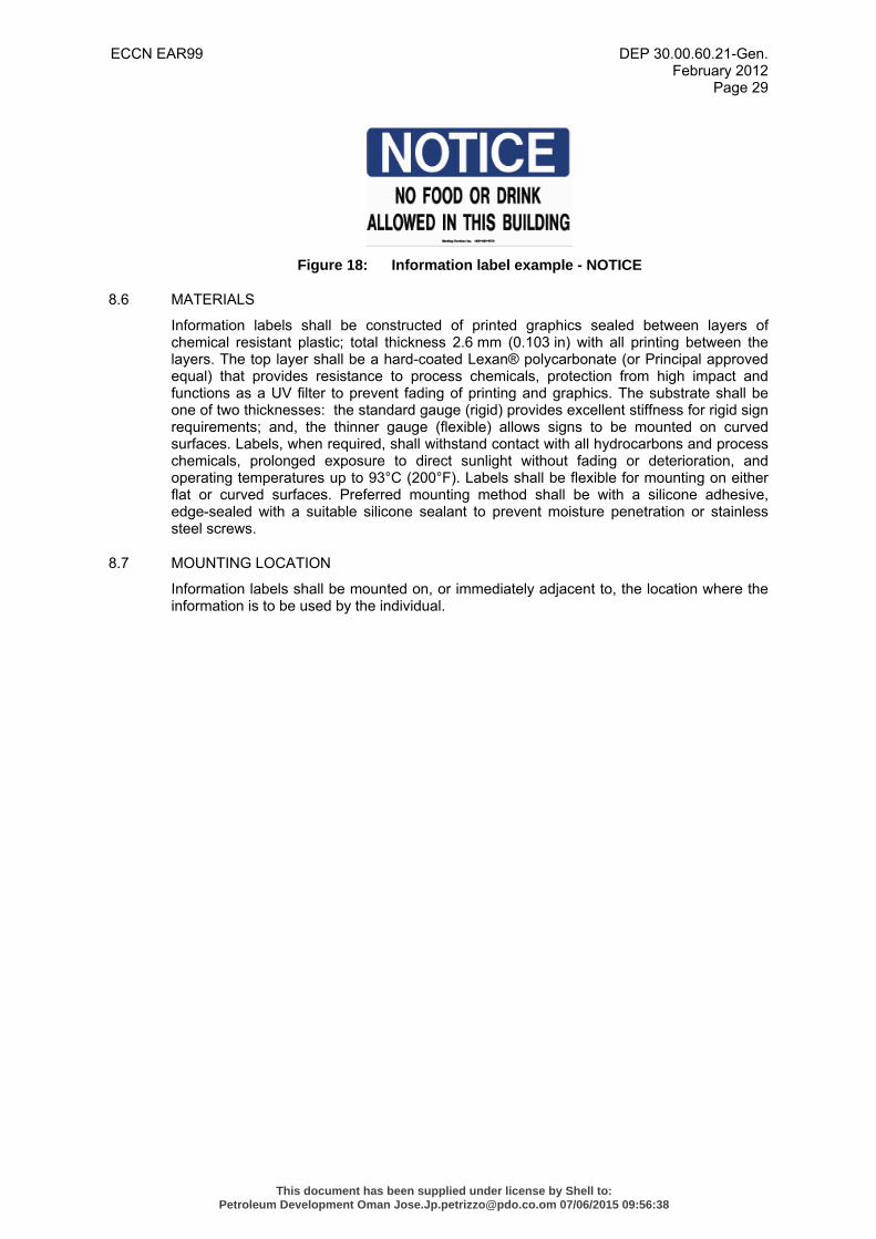
8.5 CHARACTER/BACKGROUND COLOUR
Information labels should comply with the layout and colour scheme per ANSI Z535.4 and (2), including the following properties:
• The signal-word “NOTICE” shall be white characters on a blue rectangular background.
• Text inscription shall be black characters on a white background.
This document has been supplied under license by Shell to:Petroleum Development Oman [email protected] 07/06/2015 09:56:38
ECCN EAR99 DEP 30.00.60.21-Gen. February 2012
Page 29
Figure 18: Information label example - NOTICE
8.6 MATERIALS
Information labels shall be constructed of printed graphics sealed between layers of chemical resistant plastic; total thickness 2.6 mm (0.103 in) with all printing between the layers. The top layer shall be a hard-coated Lexan® polycarbonate (or Principal approved equal) that provides resistance to process chemicals, protection from high impact and functions as a UV filter to prevent fading of printing and graphics. The substrate shall be one of two thicknesses: the standard gauge (rigid) provides excellent stiffness for rigid sign requirements; and, the thinner gauge (flexible) allows signs to be mounted on curved surfaces. Labels, when required, shall withstand contact with all hydrocarbons and process chemicals, prolonged exposure to direct sunlight without fading or deterioration, and operating temperatures up to 93°C (200°F). Labels shall be flexible for mounting on either flat or curved surfaces. Preferred mounting method shall be with a silicone adhesive, edge-sealed with a suitable silicone sealant to prevent moisture penetration or stainless steel screws.
8.7 MOUNTING LOCATION
Information labels shall be mounted on, or immediately adjacent to, the location where the information is to be used by the individual.
This document has been supplied under license by Shell to:Petroleum Development Oman [email protected] 07/06/2015 09:56:38
ECCN EAR99 DEP 30.00.60.21-Gen. February 2012
Page 30
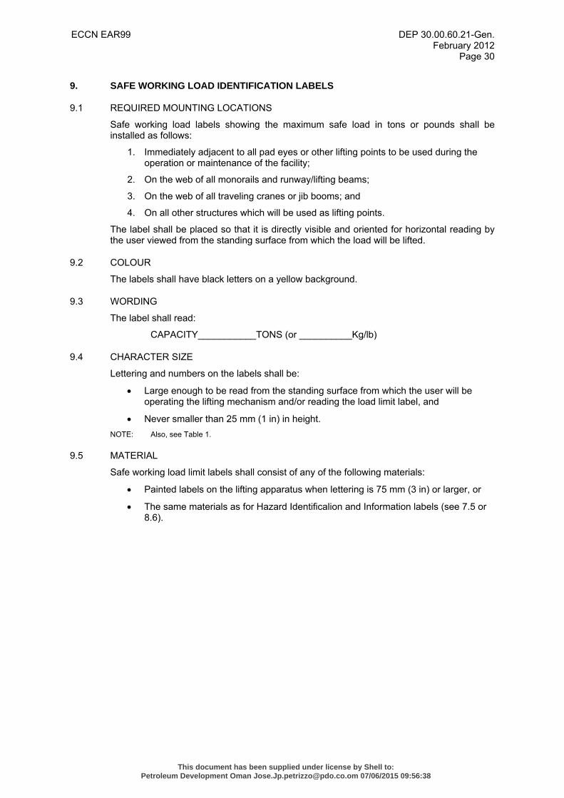
9. SAFE WORKING LOAD IDENTIFICATION LABELS
9.1 REQUIRED MOUNTING LOCATIONS
Safe working load labels showing the maximum safe load in tons or pounds shall be installed as follows:
1. Immediately adjacent to all pad eyes or other lifting points to be used during the operation or maintenance of the facility;
2. On the web of all monorails and runway/lifting beams;
3. On the web of all traveling cranes or jib booms; and
4. On all other structures which will be used as lifting points.
The label shall be placed so that it is directly visible and oriented for horizontal reading by the user viewed from the standing surface from which the load will be lifted.
9.2 COLOUR
The labels shall have black letters on a yellow background.
9.3 WORDING
The label shall read:
CAPACITY___________TONS (or __________Kg/lb)
9.4 CHARACTER SIZE
Lettering and numbers on the labels shall be:
• Large enough to be read from the standing surface from which the user will be operating the lifting mechanism and/or reading the load limit label, and
• Never smaller than 25 mm (1 in) in height. NOTE: Also, see Table 1.
9.5 MATERIAL
Safe working load limit labels shall consist of any of the following materials:
• Painted labels on the lifting apparatus when lettering is 75 mm (3 in) or larger, or
• The same materials as for Hazard Identificalion and Information labels (see 7.5 or 8.6).
This document has been supplied under license by Shell to:Petroleum Development Oman [email protected] 07/06/2015 09:56:38
ECCN EAR99 DEP 30.00.60.21-Gen. February 2012
Page 31
10. VISUAL AIDS FOR IMPROVING EQUIPMENT EFFECTIVENESS
10.1 GENERAL
Aside from the identification and informational labelling mentioned in the previous sections, this section is meant to highlight additional labelling techniques.
These techniques shall be utilized when commissioning new equipment or by the equipment Operator for existing equipment. The techniques serve to:
• Improve the equipment’s overall condition, operability, maintenance, performance, and safety, and
• Enhance and accelerate training in the equipment operation.
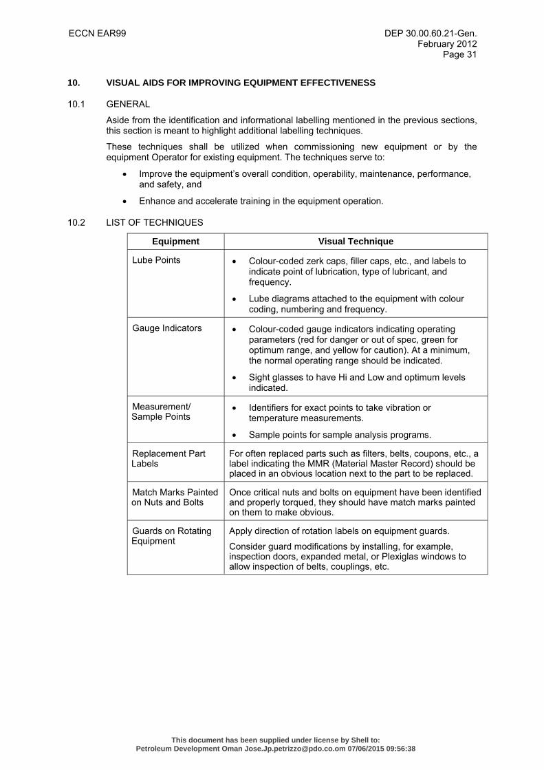
10.2 LIST OF TECHNIQUES
Equipment Visual Technique
Lube Points • Colour-coded zerk caps, filler caps, etc., and labels to indicate point of lubrication, type of lubricant, and frequency.
• Lube diagrams attached to the equipment with colour coding, numbering and frequency.
Gauge Indicators • Colour-coded gauge indicators indicating operating parameters (red for danger or out of spec, green for optimum range, and yellow for caution). At a minimum, the normal operating range should be indicated.
• Sight glasses to have Hi and Low and optimum levels indicated.
Measurement/ Sample Points
• Identifiers for exact points to take vibration or temperature measurements.
• Sample points for sample analysis programs.
Replacement Part Labels
For often replaced parts such as filters, belts, coupons, etc., a label indicating the MMR (Material Master Record) should be placed in an obvious location next to the part to be replaced.
Match Marks Painted on Nuts and Bolts
Once critical nuts and bolts on equipment have been identified and properly torqued, they should have match marks painted on them to make obvious.
Guards on Rotating Equipment
Apply direction of rotation labels on equipment guards.
Consider guard modifications by installing, for example, inspection doors, expanded metal, or Plexiglas windows to allow inspection of belts, couplings, etc.
This document has been supplied under license by Shell to:Petroleum Development Oman [email protected] 07/06/2015 09:56:38
ECCN EAR99 DEP 30.00.60.21-Gen. February 2012
Page 32
11. LABEL CATALOGUE
11.1 CONTENTS
A label catalogue should be prepared for each facility identifying each unique type of label purchased and installed in that facility. The catalogue should contain the following data:
1. Label Supplier’s name, address and phone number, and a person to contact to acquire more labels;
2. Original packing lists for purchases of certain labels so that duplicates of a specific label may be ordered from the same Supplier;
3. Any text and tag number contained on the label;
4. Label size and colour;
5. Label material;
6. The quantity of each label originally purchased; and
7. Label location and/or service.
This document has been supplied under license by Shell to:Petroleum Development Oman [email protected] 07/06/2015 09:56:38
ECCN EAR99 DEP 30.00.60.21-Gen. February 2012
Page 33
12. REFERENCES
In this DEP, reference is made to the following publications:
NOTES: 1. NOTES: 1. Unless specifically designated by date, the latest edition of each publication shall be used, together with any amendments/supplements/revisions thereto.
2. The DEPs and most referenced external standards are available to Shell staff on the SWW (Shell Wide Web) at http://sww.shell.com/standards/.
SHELL STANDARDS
Symbols and identification system - Mechanical DEP 31.10.03.10-Gen.
Instrumentation symbols and identification on process engineering flow schemes
DEP 32.10.03.10-Gen.
AMERICAN STANDARDS
American national standard for safety colors ANSI Z535.1
American national standard for environmental and facility safety signs
ANSI Z535.2
Recommended practice for analysis, design, installation, and testing of basic surface safety systems for offshore production platforms
API RP 14C
Scheme for the identification of piping systems ASME A13.1 (1996)
INTERNATIONAL STANDARDS
Graphical symbols — Safety colours and safety signs – Part 4: Colorimetric and photometric properties of safety sign materials
ISO 3864-4
Petroleum and natural gas industries — Offshore production installations — Basic surface process safety systems
ISO 10418
Ergonomic design of control centres — Part 4: Layout and dimensions of workstations
ISO 11064-4
This document has been supplied under license by Shell to:Petroleum Development Oman [email protected] 07/06/2015 09:56:38