Embed Size (px)
Citation preview

Human-machine Function Allocation-based Simulation of Ejection Seat Operation for Comfort Enhancement
Qiu Yifen, Zhang Guangwei, Liang Zhuoli, Zhuang Damin School of Aeronautic Science and Engineering
Beijing University of Aeronautics and Astronautics Beijing 100191, China
Abstract-The comfort of an ejection seat greatly influences the pilot's flight performance. To achieve the maximum comfort, a pilot needs to adjust the backrest and cushion of an ejection seat by operating its regulating assembly that is based on human-machine function allocation. It is evident that the comfort of an ejection seat has to be determined first before an effective regulating assembly can be designed. In this study, a simulation platform incorporating human body model, ejection seat and aircraft steering control system was established using computer-aided design techniques. With the virtual backrest and cushion obtained through the platform, experiments were conducted to simulate the pilot operation of an ejection seat for comfort. It showed that improving the ejection seat comfort could create an effective and comfortable driving environment for the pilot. The study provided a theoretical basis for designing the regulating assembly.
Keywords-Ejection seat, Comfort, Computer-aided design
I. INTRODUCTION
Ejection seats are commonly installed on military aircrafts for rescuing pilots in an emergency. The backrest and cushion of an ejection seat can be adjusted to provide comfort for the pilot. By operating the regulating assembly of an ejection seat, a pilot can tune the shape of the backrest to fit the physiological characteristics of his back and in turn, obtain additional comfort. To design effective regulating assemblies, however, the comfort of ejection seats needs to be first determined. Currently, fundamental research on defining the ejection seat comfort is scarce. The man, the ejection seat, and the cabin environment are not considered as an integral human-machine system [1]. With the advances of computer technologies, it is possible to virtually simulate the ejection seat comfort evaluation process.
We attempted to apply the analytical approach of man-machine function allocation to determine whether the task of adjusting the backrest and cushion should be allocated to the pilot or the automatic control system. The approach embeds the fuzzy AHP method [2] and is presented briefly as follows: at the target level, providing maximum comfort to the pilot who would work efficiently is the goal; at the criteria level, six main indicators are to be considered, including support cost, operational efficiency, the degree of comfort, reliability, safety, and maintainability; at the scheme level, adjustment of pilot operation, automatic control, and common control adjustment are taken into
account. Considering that all potential affecting factors have been included in such a multi-level hierarchical structural model and the fuzzy complementary matrix for analysis, it is reasonable to believe that the designed operating assembly, with features of high reliability, simple structure, and cost-effective, can help the pilot achieve the goal of obtaining high comfort.
II. METHOD
An ejection seat model [3] was established using Auto CAD (computer aided design) and a steering control model was setup using 3Dmax. Based on these models, a three-dimensional mannequin incorporating geometric and dynamic functions was established. By analyzing human biological features and spine mechanics properties in comfortable state and applying man-machine engineering principles and the reverse modeling technology, the mannequin was able to generate virtual ejection seats with desirable backrests and cushions according to human physiological curve characteristics. Eventually, all the models mentioned above were combined organically to construct an ejection seat computer-aided design simulation platform which is capable of simulating the human manipulation and evaluating the ejection seat comfort. The simulation platform was innovative, providing efficient research means and improving the design level of the operating assembly and the ejection seat as a whole. A. Modeling and layout of aircraft’s steering control A pilot can manipulate and direct an aircraft by operating its steering control panel in the cabin. A steering control panel typically consists of a steering column, a throttle lever, a course control pedal, and others. The layout of the main steering control components is compliant to the related demands and regulations described in ChinaGJB6145-88 [4] and ChinaGJB2873-97[5].
To examine whether or not the established steering control model was reasonable, it was necessary to measure the human body joints bending angles under the situation of the layout. The measured results in Table I reveal that all the human body joint bending angles were not in the comfortable range. The parameters were:
1θ : the angle
between the human body upper trunk and the seat backrest;
2θ : the angle between the upper arm and the trunk; 3θ :
The 2nd International Conference on Computer Application and System Modeling (2012)
Published by Atlantis Press, Paris, France. © the authors
0284

the angle between forearm and the upper arm; 4θ : the
angle between thigh and upper limbs;5θ : the angle
between shank and the thigh; 6θ : the angle between the
foot and the shank Thus, it’s necessary to optimize the layout of the steering control panel. 1) Optimizing the layout of the central steering column
and the throttle lever The coordinate system was established with considering
the seat reference point as the coordinate origin and two fixed coordinate systems were set up with the shoulder joint and elbow joint as the coordinate origins. Then the dimension of the human body model, the layout of the seat, and the comfort angle of the hand joints were all integrated through the computational methods as reported in the literature [6]. Several locations deviating from the seat central line were investigated accordingly. Based on the results, the layout situation enabling the pilot to comfortably operate the steering control panel was computed. It showed that the neutral position of the central steering handle should be placed on right 400 mm horizontally, 300 mm vertically away from the seat neutral reference point, of which the maximum backward stroke was approximately 100 mm, the maximum forward stroke approximately 80mm, and the maximum stroke between the left and the right about 150 mm. The neutral position of the throttle lever should be placed in the right location that about 350 mm horizontally, 250-350 mm vertically away from the seat neutral position, of which the forward and backward should be distanced along stroke at least 150 mm. 2) Optimizing the layout of the course pedal In order to determine the moving curve and the distance adjustment of the pedal, it is necessary to use the different percentiles of the human body size to simulate the range of the human leg activities. The layout of the pedal was optimized through solving the comfort range of the pedal shaft using reported methods [6].The computing results show that the neutral position of the pedal shaft should be placed on right 800-850 mm horizontally, more than 150mm vertically away from the reference point, of which the maximum stroke was about 120 mm and the minimum adjustment range was 100 mm. The layout of the steering control panel was re-arranged according to the computing results. Table II. shows the bending angles of the human joints measured after optimization. It can be seen that the bending angles of the joints are in the comfort range. The steering control panel model was established eventually and its relative positions with the ejection seat are shown in Figure1.
Figure 1. The “ejection seat - steering control module” model
B. Modeling of human body
A human body model represents the human geometric characteristics and behavior characteristics, including geometric model and motion model. 1) The human body geometric model The skin of the human body geometric model was represented by a layer composed of polygon meshes, while the skeleton of the model followed the H-Anim standard [7]. The overall human model was established according to the provisions of the Chinese pilots’ dimensional data in ChinaGJB4856-2003[8]. When a human body is in different sitting postures, the skeleton positions have great differences. Therefore, the human sitting posture model needs adjustment according to the demands of comfortable sitting postures, this serving as a basis for designing the backrest/cushion of an ejection seat. When a person is in a comfortable sitting posture, the angles of each part are shown in Figure.2. The human sitting posture model shown in Figure.3 is established according to the human joint angles’ range within the comfortable sitting posture.
Figure 2. The diagrammatic sketch of
Figure 3. The human sitting posture model joint angles in amenity
sitting posture 2) The human motion model Kinematic models are generally based on the rigid body
The 2nd International Conference on Computer Application and System Modeling (2012)
Published by Atlantis Press, Paris, France. © the authors
0285
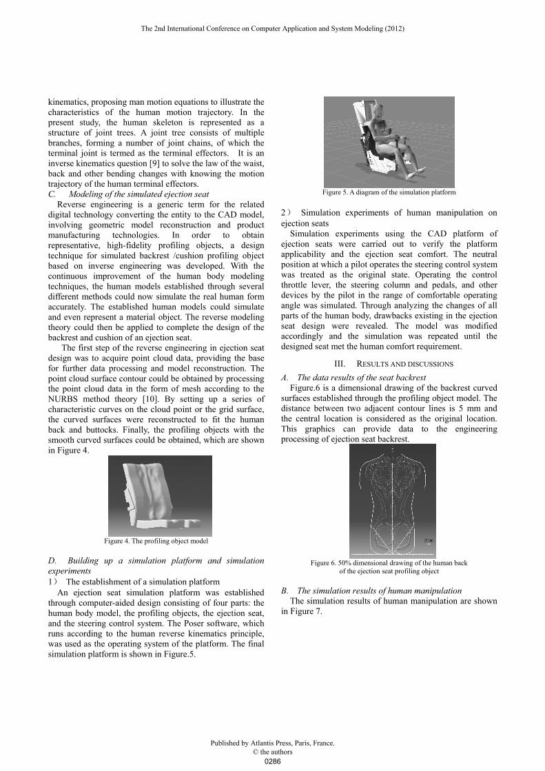
kinematics, proposing man motion equations to illustrate the characteristics of the human motion trajectory. In the present study, the human skeleton is represented as a structure of joint trees. A joint tree consists of multiple branches, forming a number of joint chains, of which the terminal joint is termed as the terminal effectors. It is an inverse kinematics question [9] to solve the law of the waist, back and other bending changes with knowing the motion trajectory of the human terminal effectors. C. Modeling of the simulated ejection seat Reverse engineering is a generic term for the related digital technology converting the entity to the CAD model, involving geometric model reconstruction and product manufacturing technologies. In order to obtain representative, high-fidelity profiling objects, a design technique for simulated backrest /cushion profiling object based on inverse engineering was developed. With the continuous improvement of the human body modeling techniques, the human models established through several different methods could now simulate the real human form accurately. The established human models could simulate and even represent a material object. The reverse modeling theory could then be applied to complete the design of the backrest and cushion of an ejection seat. The first step of the reverse engineering in ejection seat design was to acquire point cloud data, providing the base for further data processing and model reconstruction. The point cloud surface contour could be obtained by processing the point cloud data in the form of mesh according to the NURBS method theory [10]. By setting up a series of characteristic curves on the cloud point or the grid surface, the curved surfaces were reconstructed to fit the human back and buttocks. Finally, the profiling objects with the smooth curved surfaces could be obtained, which are shown in Figure 4.
Figure 4. The profiling object model
D. Building up a simulation platform and simulation experiments 1) The establishment of a simulation platform An ejection seat simulation platform was established through computer-aided design consisting of four parts: the human body model, the profiling objects, the ejection seat, and the steering control system. The Poser software, which runs according to the human reverse kinematics principle, was used as the operating system of the platform. The final simulation platform is shown in Figure.5.
Figure 5. A diagram of the simulation platform
2) Simulation experiments of human manipulation on ejection seats
Simulation experiments using the CAD platform of ejection seats were carried out to verify the platform applicability and the ejection seat comfort. The neutral position at which a pilot operates the steering control system was treated as the original state. Operating the control throttle lever, the steering column and pedals, and other devices by the pilot in the range of comfortable operating angle was simulated. Through analyzing the changes of all parts of the human body, drawbacks existing in the ejection seat design were revealed. The model was modified accordingly and the simulation was repeated until the designed seat met the human comfort requirement.
III. RESULTS AND DISCUSSIONS
A. The data results of the seat backrest Figure.6 is a dimensional drawing of the backrest curved
surfaces established through the profiling object model. The distance between two adjacent contour lines is 5 mm and the central location is considered as the original location. This graphics can provide data to the engineering processing of ejection seat backrest.
Figure 6. 50% dimensional drawing of the human back
of the ejection seat profiling object
B. The simulation results of human manipulation
The simulation results of human manipulation are shown in Figure 7.
The 2nd International Conference on Computer Application and System Modeling (2012)
Published by Atlantis Press, Paris, France. © the authors
0286

Figure 7. The curve drawing of the hip changes
Before optimization the distance that the hips need to
move forward is relatively long, as indicated in Figure.7. This is because the steering gears are not in the accessible field and not in the comfortably reachable area. Meanwhile, the ejection seat could not provide adequate support for the hips without the cushion, causing the pilot to move his hips forward to achieve the operating comfort while manipulating the pedal. The action, however, would increase the head’s positive rake and cause the lumbar vertebra to bend and touch less with the ejection seat. The simulation results show that introduction of the cushion through optimizing the steering gear layout greatly reduced the hip displacement, restricted gliding while the pilot was operating the pedal, and improved the comfort of the ejection seat. The change in the angle of the pilot’s back and waist compared with the initial state during the simulation process was nearly none. It was caused by two factors: optimization of the steering gear layout that allows the pilot to operate the aircraft comfortably without the need to change the upper trunk’s posture to expand the limbs’ sphere of activity and addition of the profiling object that enables the spine to remain in its natural state as the back and waist could contact the profiling object closely and the back muscle of the spine was relatively relaxed from balancing force requirement. The pilot would not need to change the postures frequently to relieve the soreness from the fatigue of the back and waist muscles.
IV. CONCLUSION
With the assistance of the CAD technology, we established models of ejection seat, aircraft steering control system, human pilot, and seat back/cushion profiling object according to the man-machine engineering principles. A simulation platform of the ejection seat was built up by organically integrating these models and was verified for applicability by simulated virtual human manipulating experiments. It shows that the simulation platform was fairly effective in designing comfortable ejection seats. The results provide a theoretical basis and guidance for designing position-adjustable structures such as the backrest. The study solved the man-machine function allocation problems in achieving the comfort of ejection seats.
ACKNOWLEDGMENT
Funding source: National Basic Research Program of China (Program Grant No.2010CB734104)
REFERENCES
[1] Bernotat R K. Human-machine-systems research and application. Wachtberg FRG: Research Institute for Human Engineering, 1990
[2] Zhang Jijun. Fuzzy AHP (FAHP). Fuzzy Systems and Mathematics. 2000, 14 (2): 80 ~ 88.
[3] Huang Jiayang, Qiu Yifen, Yan Yinxue, Jiang Nan. Simulation of ejection seat’s static amenity. Journal of Beijing University of Aeronautics and Astronautics.2008, 34(10):1168-1171
[4] ChinaGJB 6154-88, Geometrical dimensions of aviation cockpit [5] ChinaGJB2873-97, Man-machine engineering design principles of the
military equipments and installations [6] Yuan Xiugan, Zhuang Damin, Zhang Xingjuan, The man-machine
engineering computer simulation. Beijing. The press of Beijing University of Aeronautics and Astronautics, 2005:2-8
[7] Lv Zhiguo, Li Yan, He Hangen. The three-dimensional human body modeling methods based on the Poser model. Computer Engineering .2008
[8] ChinaGJB 4856-2003, The People's Republic of China military standards, the Chinese male pilot body size. The Chinese people’s Liberation Army General Armament Department, 2003
[9] Zhang Lei, Wang Rui, Zhuang Damin, et al. Optimized Layout of Aircraft Joystick Based on Human Model. Li Shengcai, Wang Yajun, An Ying, et al. Progress in safety science and technology, Vol. VII. Beijing: Science Press, 2008: 1968-1972
[10] Ma Weiyin, Kruth J P. NURBS Curve and Surface Fitting for Reverse Engineering. International Journal of Advanced Manufacturing Technology, 1998, 14 (12): 918-927
TABLE I. THE ANGLES OF THE HUMAN JOINTS BEFORE OPTIMIZATION
Joint angles(deg) 1θ 2θ
3θ 4θ
5θ 6θ
Comfort value 10-20 15-35 80-90 90-115 100-120 85-95
Measured value 26 46 140 118 140 140
The 2nd International Conference on Computer Application and System Modeling (2012)
Published by Atlantis Press, Paris, France. © the authors
0287

TABLE II. THE ANGLES OF THE HUMAN JOINTS AFTER OPTIMIZATION
Joint angles(deg) 1θ 2θ 3θ 4θ 5θ 6θ
Comfort value 10-20 15-35 80-90 90-115 100-120 85-95
Measured value 15 25 84 105 114 92
The 2nd International Conference on Computer Application and System Modeling (2012)
Published by Atlantis Press, Paris, France. © the authors
0288