Embed Size (px)
Citation preview
Instruction Manual
Manfred Weber
Metra Mess- und Frequenztechnik in Radebeul e.K.
Meissner Str. 58 - D-01445 Radebeul
Tel. +49-351 836 2191 Fax +49-351 836 2940
Email: [email protected] Internet: www.MMF.de
Human-VibrationAnalyzer
VM31
Published by:
Manfred Weber
Metra Mess- und Frequenztechnik in Radebeul e.K.
Meißner Str. 58
D-01445 Radebeul
Tel. +49-351-836 2191
Fax +49-351-836 2940
Email [email protected]
Internet www.MMF.de
Note: The latest version of this manual can be found at http://www.mmf.de/product_literature.htm
Specification subject to change.
© 2014 Manfred Weber Metra Mess- und Frequenztechnik in Radebeul e.K.
Full or partial reproduction subject to prior written approval.
Nov/ 14 #194
Contents1. Purpose..................................................................................................................22. The Device at a Glance..........................................................................................23. Fundamentals of Human Vibration Measurement..................................................3
3.1. Introduction....................................................................................................33.2. EU Occupational Health Directive 2002/44/EC.............................................3
4. Human Vibration Measurement with the VM31....................................................74.1. Batteries.........................................................................................................74.2. Switching on and Connecting the Sensor.......................................................84.3. Hand-Arm Measurement with the VM31.......................................................9
4.3.1. Measuring Points for Hand-Arm Vibration.............................................94.3.2. VM31 Settings......................................................................................10
4.4. Whole-Body Measurement with the VM31..................................................114.4.1. Measuring Points for Whole-Body Vibration.......................................124.4.2. VM31 Settings......................................................................................13
4.4.2.1. Whole-Body Measurement with RMS Values...............................134.4.2.2. Whole-Body Vibration Measurement with VDV Values...............174.4.2.3. Seat Effective Amplitude Transmissibility (SEAT)........................18
5. General Vibration Measurement..........................................................................186. Frequency Analysis..............................................................................................217. Data Memory.......................................................................................................218. Keypad Lock........................................................................................................229. Device Settings....................................................................................................22
9.1. Sensor Calibration........................................................................................229.2. Time and Date..............................................................................................229.3. Shut-off Timer..............................................................................................239.4. Battery Type.................................................................................................239.5. Display Brightness........................................................................................239.6. Menu Language............................................................................................239.7. Default Settings............................................................................................24
10. Reset Key...........................................................................................................2411. Connection to a PC............................................................................................2412. Data Transfer to a PC.........................................................................................25
12.1. Opening the Excel File vm31.xlsm.............................................................2512.2. Data Import to Excel..................................................................................2612.3. Calculation of Vibration Exposure A(8) and VDV(8)................................2612.4. FFT Data Import to Excel...........................................................................27
13. Firmware Update...............................................................................................2814. Calibration.........................................................................................................2915. Technical Data...................................................................................................31 Limited Warranty....................................................................................................32
Appendix: WarrantyDeclaration of CE Conformity
1
Thank you for choosing a Metra Vibration Measurement device!
1. PurposeThe VM31 has been developed, particularly, for the measurement and analysis ofhuman vibration. Other fields of application include machine condition monitoring,building vibration measurement and quality control.
In combination with a triaxial accelerometer, hand-arm and whole-body vibrationscan be measured in compliance with ISO 5349, ISO 2631 and the EU Directive2002/44/EC. A fourth measuring channel can be used, for example, for SEAT mea-surements (seat effective acceleration transmissibility).
The VM31 meets the requirements for human vibration meters in compliance withISO 8041. In the development of the VM31 value was placed on simple operationand compact design.
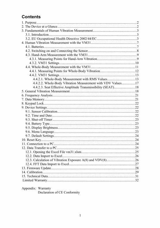
2. The Device at a Glance
2
Figure 1: Controls, connectors and display

3. Fundamentals of Human Vibration Measurement
3.1. IntroductionVibrations affecting the human body are called human vibration. The main purposeof measuring human vibration is the prevention of health risks and the evaluation ofcomfort, for example in vehicles.
Two categories are distinguished:
• Hand-Arm Vibrations, which are induced via the hands into the body. Theymay cause, for example, circulatory disorder, bone, joint or muscle diseases.
• Whole-Body Vibrations, acting via the buttocks, the back and the feet of a sit-ting person, the feet of a standing person or the back and the head of a recumbentperson. Such vibrations may cause backache or damage to the spinal column.
Both types of human vibration measurement are described in international standards:
• ISO 5349 - Measurement and evaluation of human exposure to hand-transmittedvibration
• ISO 2631 - Evaluation of human exposure to whole-body vibration (also ASA/ANSI S3.18)
• ISO 8041 - Human response to vibration. Measuring Instrumentation
• ISO 8662 - Hand-held portable power tools - Measurement of vibrations at the handle
• ISO 6954 - Guidelines for the measurement, reporting and evaluation of vibra-tion with regard to habitability on passenger and merchant ships
• ISO 10056 - Measurement and analysis of whole-body vibration to which pas-sengers and crew are exposed in railway vehicles
• ISO 10326 - Laboratory method for evaluating vehicle seat vibration
• ISO 28927 - Hand-held portable power tools - Test methods for evaluation of vi-bration emission
Practical advice for measurement and evaluation of human vibration can be found inVDI 2057.
The subject of human vibration has gained particular importance in Europe since thedirective 2002/44/EC came into effect. It specifies the duties of employers with re-gard to workers protection.
3.2. EU Occupational Health Directive 2002/44/ECThe following text is an abstract of Directive 2002/44/EC of the European Parlia-ment and of the Council dated June 25, 2002. The complete text can be downloadedfrom http://eur-lex.europa.eu/
The directive specifies minimum requirements for the protection of workers fromthe risks arising from vibrations. Manufacturers of machines and employers shouldmake adjustments regarding risks related to exposure to vibration.
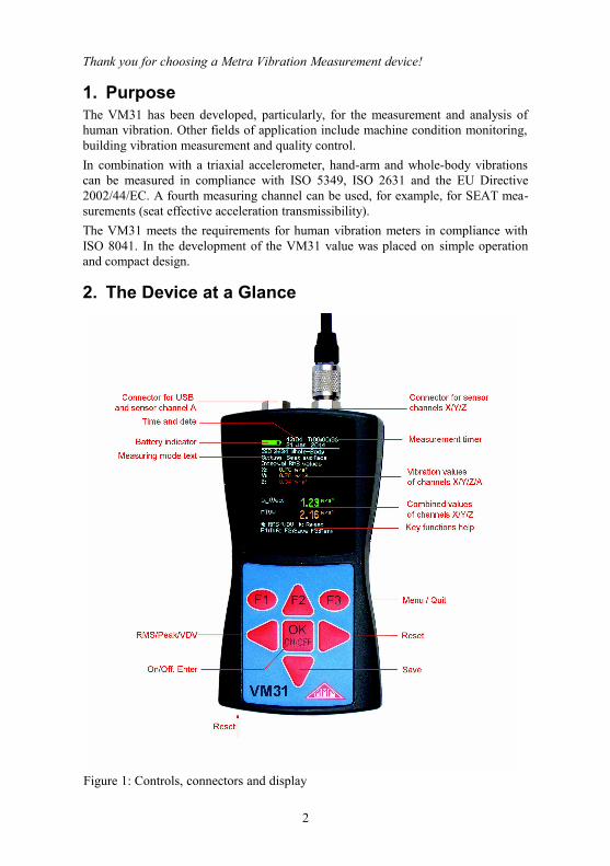
The directive lays down the following limit values:
3
Hand-Arm, RMS Whole-Body, RMS Whole-Body, VDV
Exposure action value 2.5 m/s² 0.5 m/s² 9.1 m/s1,75
Exposure limit 5 m/s² 1.15 m/s² 21 m/s1,75
Table 1: Limits to EU directive 2002/44/EC
Once the exposure action value is exceeded, the employer shall establish and im-plement a program of technical and organizational measures intended to reduce to aminimum exposure to mechanical vibration, taking into account in particular:
• Other working methods that require less exposure to mechanical vibration
• Appropriate work equipment of ergonomic design, producing the least possiblevibration
• Provision of auxiliary equipment that reduces the risk of injuries, such as protec-tive gloves or special seats
• Appropriate maintenance programs for work equipment
• Design and layout of workplaces
• Adequate information and training to instruct workers to use work equipmentcorrectly and safely
• Limitation of the duration and intensity of the exposure
• Work schedules with adequate rest periods
• Provision of clothing to protect workers from cold and damp
In any event, workers shall not be exposed above the exposure limit value. If thisshould be the case, the employer shall take immediate action to reduce exposure be-low the exposure limit value.
The methods used may include sampling, which must be representative of the per-sonal exposure of a worker to the mechanical vibration in question.
The assessment of the level of exposure to vibration is based on the calculation ofdaily exposure A(8) expressed as equivalent continuous acceleration over an eight-hour work period. For the determination of A(8) it is not necessary to measure overeight hours. It is sufficient to make short-term measurements during representativework steps. The results are normalized to eight hours. Daily exposure is calculatedas follows:
A(8)=a we√ T e
T 0
Equation 1
where
A(8) is the daily exposure
awe is the energy equivalent mean value of the frequency weighted acceleration during exposure, which means
4
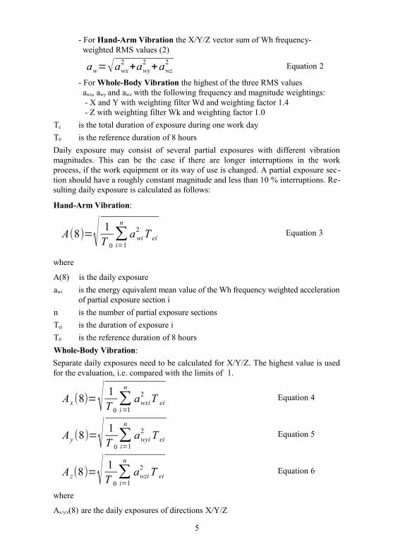
- For Hand-Arm Vibration the X/Y/Z vector sum of Wh frequency- weighted RMS values (2)
aw=√awx2
+awy2
+awz2 Equation 2
- For Whole-Body Vibration the highest of the three RMS values awx, awy and awz with the following frequency and magnitude weightings: - X and Y with weighting filter Wd and weighting factor 1.4 - Z with weighting filter Wk and weighting factor 1.0
Te is the total duration of exposure during one work day
T0 is the reference duration of 8 hours
Daily exposure may consist of several partial exposures with different vibrationmagnitudes. This can be the case if there are longer interruptions in the workprocess, if the work equipment or its way of use is changed. A partial exposure sec-tion should have a roughly constant magnitude and less than 10 % interruptions. Re-sulting daily exposure is calculated as follows:
Hand-Arm Vibration:
A(8)=√ 1T 0
∑i=1
n
a wi2 T ei
Equation 3
where
A(8) is the daily exposure
awi is the energy equivalent mean value of the Wh frequency weighted accelerationof partial exposure section i
n is the number of partial exposure sections
Tei is the duration of exposure i
T0 is the reference duration of 8 hours
Whole-Body Vibration:
Separate daily exposures need to be calculated for X/Y/Z. The highest value is usedfor the evaluation, i.e. compared with the limits of 1.
A x (8)=√ 1T 0
∑i=1
n
awxi2 T ei
Equation 4
A y (8)=√ 1T 0
∑i=1
n
awyi2 T ei
Equation 5
A z(8)=√ 1T 0
∑i=1
n
awzi2 T ei
Equation 6
where
Ax/y/z(8) are the daily exposures of directions X/Y/Z
5
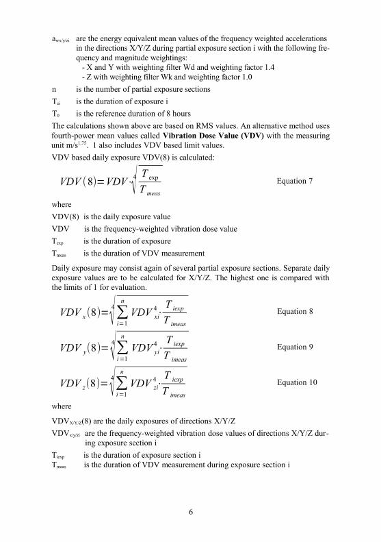
awx/y/zi are the energy equivalent mean values of the frequency weighted accelerations in the directions X/Y/Z during partial exposure section i with the following fre-quency and magnitude weightings: - X and Y with weighting filter Wd and weighting factor 1.4 - Z with weighting filter Wk and weighting factor 1.0
n is the number of partial exposure sections
Tei is the duration of exposure i
T0 is the reference duration of 8 hours
The calculations shown above are based on RMS values. An alternative method usesfourth-power mean values called Vibration Dose Value (VDV) with the measuringunit m/s1,75. 1 also includes VDV based limit values.
VDV based daily exposure VDV(8) is calculated:
VDV (8)=VDV⋅4√ T exp
T meas
Equation 7
where
VDV(8) is the daily exposure value
VDV is the frequency-weighted vibration dose value
Texp is the duration of exposure
Tmeas is the duration of VDV measurement
Daily exposure may consist again of several partial exposure sections. Separate dailyexposure values are to be calculated for X/Y/Z. The highest one is compared withthe limits of 1 for evaluation.
VDV x (8)=4√∑i=1
n
VDV xi4⋅
T iexp
T imeas
Equation 8
VDV y(8)=4√∑i=1
n
VDV yi4⋅
T iexp
T imeas
Equation 9
VDV z(8)=4√∑i=1
n
VDV zi4⋅
T iexp
T imeas
Equation 10
where
VDVX/Y/Z(8) are the daily exposures of directions X/Y/Z
VDVx/y/zi are the frequency-weighted vibration dose values of directions X/Y/Z dur-ing exposure section i
Tiexp is the duration of exposure section i Tmeas is the duration of VDV measurement during exposure section i
6
Model VM31 measures Hand-Arm and Whole-Body vibration, the latter as RMS orVDV values. For the calculation of daily exposure an Excel sheet with a data importfunction is provided.
4. Human Vibration Measurement with the VM31
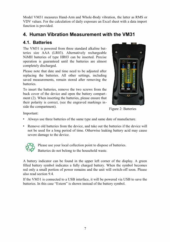
4.1. BatteriesThe VM31 is powered from three standard alkaline bat-teries size AAA (LR03). Alternatively rechargeableNiMH batteries of type HR03 can be inserted. Preciseoperation is guaranteed until the batteries are almostcompletely discharged.
Please note that date and time need to be adjusted afterreplacing the batteries. All other settings, includingsaved measurements, remain stored after removing thebatteries.
To insert the batteries, remove the two screws from theback cover of the device and open the battery compart-ment (2). When inserting the batteries, please ensure thattheir polarity is correct, (see the engraved markings in-side the compartment).
Important:
• Always use three batteries of the same type and same date of manufacture.
• Remove old batteries from the device, and take out the batteries if the device willnot be used for a long period of time. Otherwise leaking battery acid may causesevere damage to the device.
Please use your local collection point to dispose of batteries.
Batteries do not belong to the household waste.
A battery indicator can be found in the upper left corner of the display. A greenfilled battery symbol indicates a fully charged battery. When the symbol becomesred only a small portion of power remains and the unit will switch-off soon. Pleasealso read section 9.4.
If the VM31 is connected to a USB interface, it will be powered via USB to save thebatteries. In this case “Extern” is shown instead of the battery symbol.
7
Figure 2: Batteries
4.2. Switching on and Connecting the SensorSwitch on the VM31 by pressing the ON/OFF key.
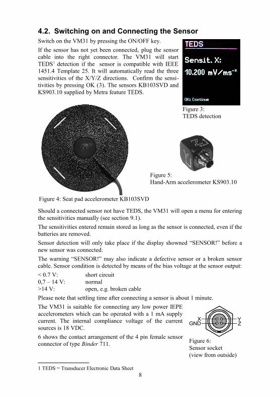
If the sensor has not yet been connected, plug the sensorcable into the right connector. The VM31 will startTEDS1 detection if the sensor is compatible with IEEE1451.4 Template 25. It will automatically read the threesensitivities of the X/Y/Z directions. Confirm the sensi-tivities by pressing OK (3). The sensors KB103SVD andKS903.10 supplied by Metra feature TEDS.
Should a connected sensor not have TEDS, the VM31 will open a menu for enteringthe sensitivities manually (see section 9.1).
The sensitivities entered remain stored as long as the sensor is connected, even if thebatteries are removed.
Sensor detection will only take place if the display showned “SENSOR!” before anew sensor was connected.
The warning “SENSOR!” may also indicate a defective sensor or a broken sensorcable. Sensor condition is detected by means of the bias voltage at the sensor output:
< 0.7 V: short circuit0,7 – 14 V: normal>14 V: open, e.g. broken cable
Please note that settling time after connecting a sensor is about 1 minute.
The VM31 is suitable for connecting any low power IEPEaccelerometers which can be operated with a 1 mA supplycurrent. The internal compliance voltage of the currentsources is 18 VDC.
6 shows the contact arrangement of the 4 pin female sensorconnector of type Binder 711.
1 TEDS = Transducer Electronic Data Sheet8
Figure 3: TEDS detection
Figure 4: Seat pad accelerometer KB103SVD
Figure 5: Hand-Arm accelerometer KS903.10
Figure 6: Sensor socket (view from outside)
GNDX Y
Z
4.3. Hand-Arm Measurement with the VM31This section will give you basic instructions for the measurement and evaluation ofhand-arm vibrations based on the standard ISO 5349 and the guideline VDI 2057,Part 2. Please consult the original documents for detailed explanations.
4.3.1. Measuring Points for Hand-Arm Vibration
The sensors should be attached as close as possible to the gripping points of thehand, however, they must not interfere with the work process. Measurement shouldbe performed with the same hand pressure force as used under normal operatingconditions.
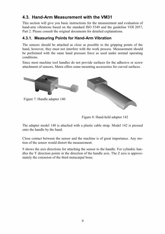
Since most machine tool handles do not provide surfaces for the adhesive or screwattachment of sensors, Metra offers some mounting accessories for curved surfaces.
The adapter model 140 is attached with a plastic cable strap. Model 142 is pressedonto the handle by the hand.
Close contact between the sensor and the machine is of great importance. Any mo-tion of the sensor would distort the measurement.
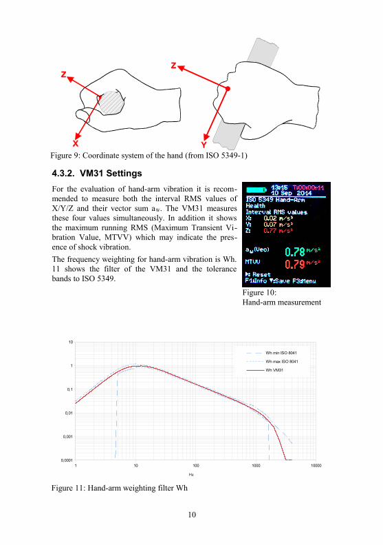
9 shows the axis directions for attaching the sensor to the handle. For cylindric han-dles the Y direction points in the direction of the handle axis. The Z axis is approxi-mately the extension of the third metacarpal bone.
9
Figure 7: Handle adapter 140
Figure 8: Hand-held adapter 142
4.3.2. VM31 Settings
For the evaluation of hand-arm vibration it is recom-mended to measure both the interval RMS values ofX/Y/Z and their vector sum aW. The VM31 measuresthese four values simultaneously. In addition it showsthe maximum running RMS (Maximum Transient Vi-bration Value, MTVV) which may indicate the pres-ence of shock vibration.
The frequency weighting for hand-arm vibration is Wh.11 shows the filter of the VM31 and the tolerancebands to ISO 5349.
10
Figure 10: Hand-arm measurement
Figure 9: Coordinate system of the hand (from ISO 5349-1)
Figure 11: Hand-arm weighting filter Wh
1 10 100 1000 100000,0001
0,001
0,01
0,1
1
10
Wh min ISO 8041
Wh max ISO 8041
Wh VM31
Hz
Press the F3 key to open the main menu and select “Human vibration” / “Hand-ArmISO 5349”/„Health“. After returning to the measurement screen (10) you can checkthe settings by pressing F1.
Measurement can begin when the sensor and the worker's hands have been placedon the handle of the object carrying out the operation. To start the measurementpress the key ► (Reset). This will result in the following:• the RMS values of X/Y/Z, the vector sum aW and MTVV reset to zero• the measurement timer restarts.
Pressing Reset before a measurement is mandatory to establish defined start condi-tions.
The RMS values of X/Y/Z and the vector sum are averaged over the entire measur -ing time. That's why fluctuation becomes less the longer the measurement takes. Af-ter a while short shock pulses have almost no influence on the displayed results .
Recommended measuring time for hand-arm vibration is at least 30 seconds. Themeasuring timer in the upper right corner remains red until 30 second have elapsed.
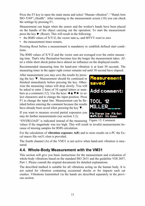
After measurement you may save the results by press-ing the key ▼. Measurement should be continued orfinished immediately before pressing the key. Other-wise the measuring values will drop slowly. You willbe asked to enter 2 lines of 10 capital letters or num-bers as a comment (12). Use the keys ◄▲▼► to se-lect characters and to change the input position. PressF1 to change the input line. Measurement can be fin-ished before entering the comment because the resultshave already been saved when pressing the key ▼.
If you want to measure several partial exposures youmay do further measurements (see section 3.2).
“OVERLOAD” is indicated instead of the measuringvalues if the magnitude was too high. This will result in invalid measurements be-cause of missing samples for RMS calculation.
For the calculation of vibration exposure A(8) and to store results on a PC the Ex-cel macro file vm31.xlsm is provided.
The fourth channel (A) of the VM31 is not active when hand-arm vibration is mea-sured.
4.4. Whole-Body Measurement with the VM31This section will give you basic instructions for the measurement and evaluation ofwhole-body vibrations based on the standard ISO 2631 and the guideline VDI 2057,Part 1. Please consult the original documents for detailed explanations.
The described method is suitable for all vibrations acting on the human body. It isnot suited for vibration containing occasional shocks or for impacts such carcrashes. Vibrations transmitted via the hands are described separately in the previ -ous section.
11
Figure 12: Comment
4.4.1. Measuring Points for Whole-Body VibrationWhole-body vibration is usually measured with seat pad accelerometers. These aretriaxial piezoelectric sensors built into a flat rubber pad, which adapt themselves tothe interface between the vibration source and the test person (4).
The following measuring points are suitable:• On the seat surface under a seated person
• On the back rest behind a seated person
• Under the feet of a seated person
• Under the feet of a standing person
• Under the pelvis of a recumbent person
• Under the head of a recumbent person
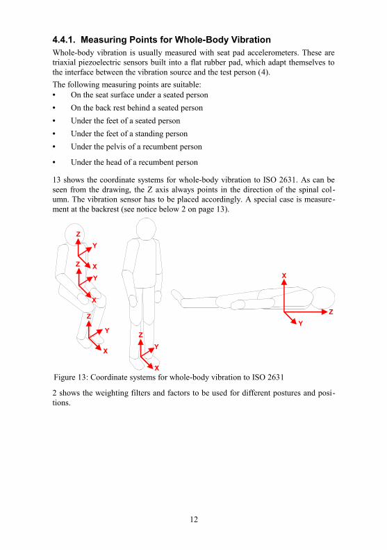
13 shows the coordinate systems for whole-body vibration to ISO 2631. As can beseen from the drawing, the Z axis always points in the direction of the spinal col-umn. The vibration sensor has to be placed accordingly. A special case is measure-ment at the backrest (see notice below 2 on page 13).
2 shows the weighting filters and factors to be used for different postures and posi-tions.
12
Figure 13: Coordinate systems for whole-body vibration to ISO 2631
Z
Y
Z
Y
Z
X
Y
Z
XX
Y
X
Y
Z
X
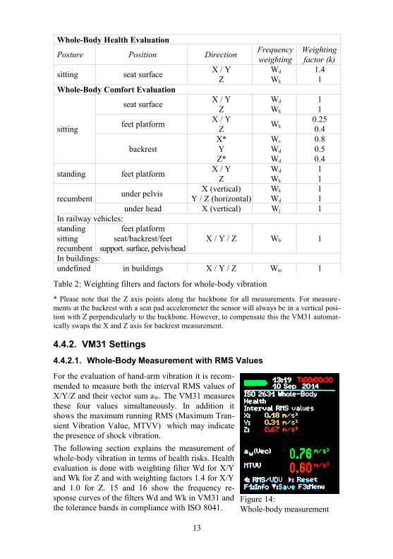
Whole-Body Health Evaluation
Posture Position DirectionFrequencyweighting
Weightingfactor (k)
sitting seat surfaceX / Y
ZWd
Wk
1.41
Whole-Body Comfort Evaluation
sitting
seat surfaceX / Y
ZWd
Wk
11
feet platformX / Y
ZWk
0.250.4
backrestX*YZ*
Wc
Wd
Wd
0.80.50.4
standing feet platformX / Y
ZWd
Wk
11
recumbentunder pelvis
X (vertical)Y / Z (horizontal)
Wk
Wd
11
under head X (vertical) Wj 1In railway vehicles:standingsittingrecumbent
feet platformseat/backrest/feet
support. surface, pelvis/headX / Y / Z Wb 1
In buildings:undefined in buildings X / Y / Z Wm 1
Table 2: Weighting filters and factors for whole-body vibration
* Please note that the Z axis points along the backbone for all measurements. For measure -ments at the backrest with a seat pad accelerometer the sensor will always be in a vertical posi-tion with Z perpendicularly to the backbone. However, to compensate this the VM31 automat-ically swaps the X and Z axis for backrest measurement.
4.4.2. VM31 Settings
4.4.2.1. Whole-Body Measurement with RMS Values
For the evaluation of hand-arm vibration it is recom-mended to measure both the interval RMS values ofX/Y/Z and their vector sum aW. The VM31 measuresthese four values simultaneously. In addition itshows the maximum running RMS (Maximum Tran-sient Vibration Value, MTVV) which may indicatethe presence of shock vibration.
The following section explains the measurement ofwhole-body vibration in terms of health risks. Healthevaluation is done with weighting filter Wd for X/Yand Wk for Z and with weighting factors 1.4 for X/Yand 1.0 for Z. 15 and 16 show the frequency re-sponse curves of the filters Wd and Wk in VM31 andthe tolerance bands in compliance with ISO 8041.
13
Figure 14: Whole-body measurement
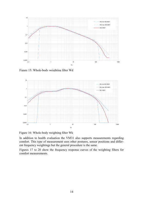
In addition to health evaluation the VM31 also supports measurements regardingcomfort. This type of measurement uses other postures, sensor positions and differ-ent frequency weightings but the general procedure is the same.
Figures 17 to 20 show the frequency response curves of the weighting filters forcomfort measurements.
14
Figure 15: Whole-body weighting filter Wd
0,1 1 10 100 10000,0001
0,001
0,01
0,1
1
10
Wd min ISO 8041
Wd max ISO 8041
Wd VM31
Hz
Figure 16: Whole-body weighting filter Wk
0,1 1 10 100 10000,0001
0,001
0,01
0,1
1
10
Wk min ISO 8041
Wk max ISO 8041
Wk VM31
Hz
15
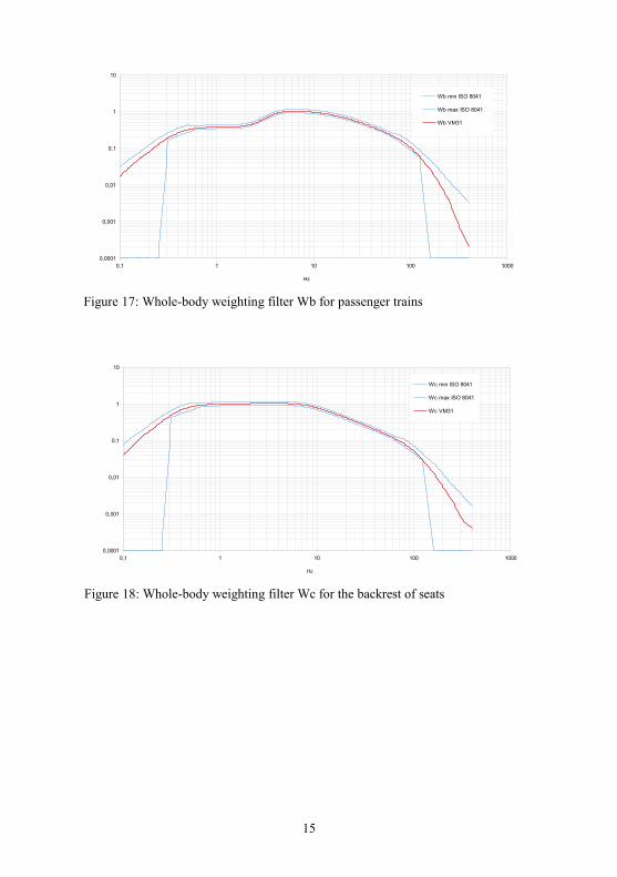
Figure 17: Whole-body weighting filter Wb for passenger trains
0,1 1 10 100 10000,0001
0,001
0,01
0,1
1
10
Wb min ISO 8041
Wb max ISO 8041
Wb VM31
Hz
Figure 18: Whole-body weighting filter Wc for the backrest of seats
0,1 1 10 100 10000,0001
0,001
0,01
0,1
1
10
Wc min ISO 8041
Wc max ISO 8041
Wc VM31
Hz
To start whole-body vibration measurement for the assessment of health risks openthe main menu by pressing F3, and select “Measuring mode” / “Human vibration” /“Whole-body ISO 2631” / “Health”. From this menu you will return to the measur -ing screen (14). You may press F1 to check your settings.
Press the key ◄ to switch from VDV to RMS if necessary.
If the worker being tested is sitting in the right position and vibration exposure hasstarted, press the key ► key (Reset) to:• reset the RMS values of X/Y/Z, the vector sum aW and MTVV to zero• restart the measurement timer.
Always press Reset before a measurement to establish the defined start conditions.
16
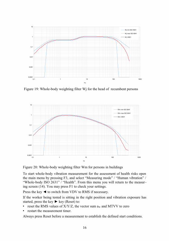
Figure 20: Whole-body weighting filter Wm for persons in buildings
0,1 1 10 100 10000,0001
0,001
0,01
0,1
1
10
Wm min ISO 8041
Wm max ISO 8041
Wm VM31
Hz
Figure 19: Whole-body weighting filter Wj for the head of recumbent persons
0,1 1 10 100 10000,0001
0,001
0,01
0,1
1
10
Wj min ISO 8041
Wj max ISO 8041
Wj VM31
Hz
The RMS values of X/Y/Z and the vector sum are averaged over the entire measur -ing time. That's why fluctuation becomes less the longer the measurement takes. Af-ter a while short shock pulses have almost no influence on the the displayed resultsanymore.
The recommended measuring time for hand-arm vibration is at least 2 minutes. Toalert you, the timer in the upper right corner remains red until 2 minutes haveelapsed.
After measurement you may save the results by pressing the key ▼. Measurementshould be either continued or finished immediately before pressing the key. Other-wise the measuring values will drop slowly. You will be asked to enter 2 lines of 10capital letters or numbers as a comment (12, page 11). Use the keys ◄▲▼► to se-lect characters and to change the input position. Press F1 to change the input line.Measurement can be finished before entering a comment because the results willhave already been saved by pressing the key ▼.
If you want to measure several partial exposures you may now do further measure-ments (see section 3.2).
“OVERLOAD” is indicated instead of the measuring values if the magnitude is toohigh. This will result in invalid measurements because of missing samples for RMScalculation.
For the calculation of vibration exposure A(8) and to store results on a PC the Ex-cel macro file vm31.xlsm is provided.
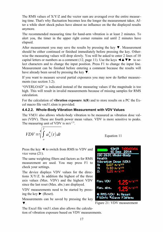
4.4.2.2. Whole-Body Vibration Measurement with VDV Values
The VM31 also allows whole-body vibration to be measured as vibration dose val-ues (VDV). These are fourth power mean values. VDV is more sensitive to peaks.The measuring unit of VDV is m/s1,75.
Equation 11
Press the key ◄ to switch from RMS to VDV andvice versa (21).
The same weighting filters and factors as for RMSmeasurement are used. You may press F1 tocheck your settings.
The device displays VDV values for the direc-tions X/Y/Z. In addition the highest of the threeaxis values (Max. VDV) and the highest VDVsince the last reset (Max. abs.) are displayed.
VDV measurements need to be started by press-ing the key ► (Reset).
Measurements can be saved by pressing the key▼.
The Excel file vm31.xlsm also allows the calcula-tion of vibration exposure based on VDV measurements.
17
Figure 21: VDV measurement
VDV =4√∫
o
T
aw4(t)dt
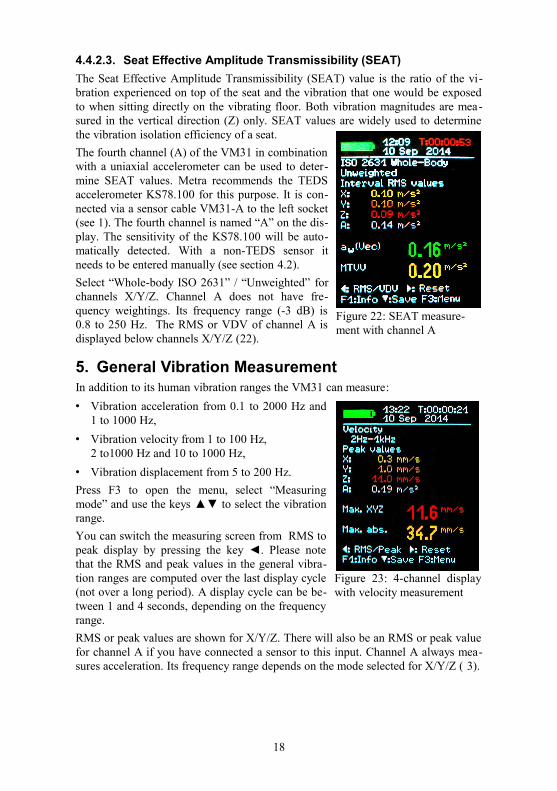
4.4.2.3. Seat Effective Amplitude Transmissibility (SEAT)
The Seat Effective Amplitude Transmissibility (SEAT) value is the ratio of the vi-bration experienced on top of the seat and the vibration that one would be exposedto when sitting directly on the vibrating floor. Both vibration magnitudes are mea-sured in the vertical direction (Z) only. SEAT values are widely used to determinethe vibration isolation efficiency of a seat.
The fourth channel (A) of the VM31 in combinationwith a uniaxial accelerometer can be used to deter-mine SEAT values. Metra recommends the TEDSaccelerometer KS78.100 for this purpose. It is con-nected via a sensor cable VM31-A to the left socket(see 1). The fourth channel is named “A” on the dis-play. The sensitivity of the KS78.100 will be auto-matically detected. With a non-TEDS sensor itneeds to be entered manually (see section 4.2).
Select “Whole-body ISO 2631” / “Unweighted” forchannels X/Y/Z. Channel A does not have fre-quency weightings. Its frequency range (-3 dB) is0.8 to 250 Hz. The RMS or VDV of channel A isdisplayed below channels X/Y/Z (22).
5. General Vibration MeasurementIn addition to its human vibration ranges the VM31 can measure:
• Vibration acceleration from 0.1 to 2000 Hz and1 to 1000 Hz,
• Vibration velocity from 1 to 100 Hz,2 to1000 Hz and 10 to 1000 Hz,
• Vibration displacement from 5 to 200 Hz.
Press F3 to open the menu, select “Measuringmode” and use the keys ▲▼ to select the vibrationrange.
You can switch the measuring screen from RMS topeak display by pressing the key ◄. Please notethat the RMS and peak values in the general vibra-tion ranges are computed over the last display cycle(not over a long period). A display cycle can be be-tween 1 and 4 seconds, depending on the frequencyrange.
RMS or peak values are shown for X/Y/Z. There will also be an RMS or peak valuefor channel A if you have connected a sensor to this input. Channel A always mea-sures acceleration. Its frequency range depends on the mode selected for X/Y/Z ( 3).
18
Figure 22: SEAT measure-ment with channel A
Figure 23: 4-channel displaywith velocity measurement
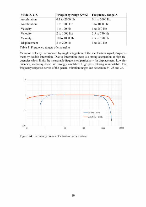
Mode X/Y/Z Frequency range X/Y/Z Frequency range A
Acceleration 0.1 to 2000 Hz 0.1 to 2000 Hz
Acceleration 1 to 1000 Hz 3 to 1000 Hz
Velocity 1 to 100 Hz 1 to 250 Hz
Velocity 2 to 1000 Hz 2.5 to 750 Hz
Velocity 10 to 1000 Hz 2.5 to 750 Hz
Displacement 5 to 200 Hz 1 to 250 Hz
Table 3: Frequency ranges of channel A
Vibration velocity is computed by single integration of the acceleration signal, displace-ment by double integration. Due to integration there is a strong attenuation at high fre-quencies which limits the measurable frequencies, particularly for displacement. Low fre-quencies, including noise, are strongly amplified. High pass filtering is inevitable. Thefrequency response curves of the general vibration ranges can be seen in 24, 25 and 26.
19
Figure 24: Frequency ranges of vibration acceleration
0,1 1 10 100 1000 100000,01
0,1
1
10
a: 1Hz – 1kHz
a: 0,1 Hz – 2 kHz
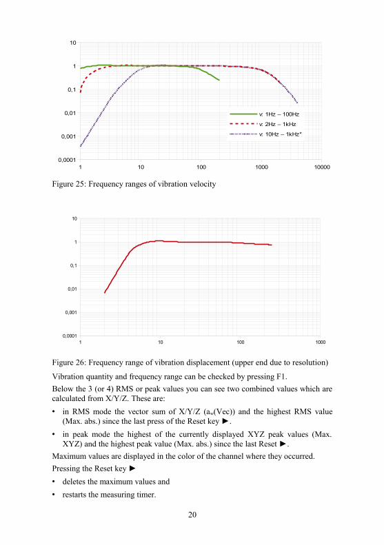
Figure 25: Frequency ranges of vibration velocity
Vibration quantity and frequency range can be checked by pressing F1.
Below the 3 (or 4) RMS or peak values you can see two combined values which arecalculated from X/Y/Z. These are:
• in RMS mode the vector sum of X/Y/Z (aw(Vec)) and the highest RMS value(Max. abs.) since the last press of the Reset key ►.
• in peak mode the highest of the currently displayed XYZ peak values (Max.XYZ) and the highest peak value (Max. abs.) since the last Reset ►.
Maximum values are displayed in the color of the channel where they occurred.
Pressing the Reset key ►
• deletes the maximum values and
• restarts the measuring timer.
20
1 10 100 1000 100000,0001
0,001
0,01
0,1
1
10
v: 1Hz – 100Hz
v: 2Hz – 1kHz
v: 10Hz – 1kHz*
Figure 26: Frequency range of vibration displacement (upper end due to resolution)
1 10 100 10000,0001
0,001
0,01
0,1
1
10
Measurements can be saved by pressing the key ▼.
The Excel file vm31.xlsm can be used to transfer the measurements to a PC.
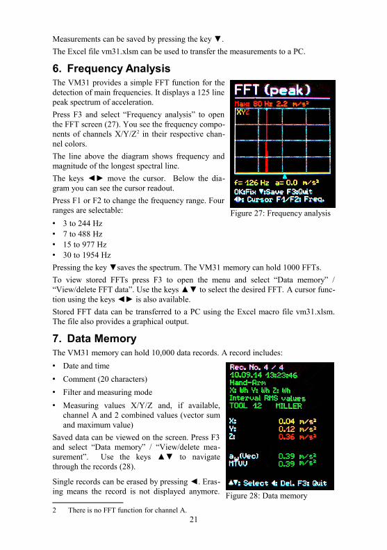
6. Frequency AnalysisThe VM31 provides a simple FFT function for thedetection of main frequencies. It displays a 125 linepeak spectrum of acceleration.
Press F3 and select “Frequency analysis” to openthe FFT screen (27). You see the frequency compo-nents of channels X/Y/Z2 in their respective chan-nel colors.
The line above the diagram shows frequency andmagnitude of the longest spectral line.
The keys ◄► move the cursor. Below the dia-gram you can see the cursor readout.
Press F1 or F2 to change the frequency range. Fourranges are selectable:
• 3 to 244 Hz• 7 to 488 Hz• 15 to 977 Hz• 30 to 1954 Hz
Pressing the key ▼saves the spectrum. The VM31 memory can hold 1000 FFTs.
To view stored FFTs press F3 to open the menu and select “Data memory” /“View/delete FFT data”. Use the keys ▲▼ to select the desired FFT. A cursor func-tion using the keys ◄► is also available.
Stored FFT data can be transferred to a PC using the Excel macro file vm31.xlsm.The file also provides a graphical output.
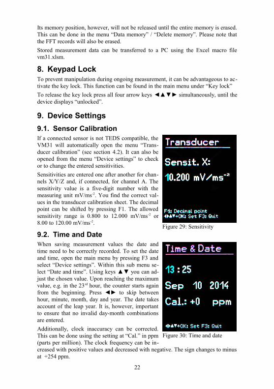
7. Data MemoryThe VM31 memory can hold 10,000 data records. A record includes:
• Date and time
• Comment (20 characters)
• Filter and measuring mode
• Measuring values X/Y/Z and, if available,channel A and 2 combined values (vector sumand maximum value)
Saved data can be viewed on the screen. Press F3and select “Data memory” / “View/delete mea-surement”. Use the keys ▲▼ to navigatethrough the records (28).
Single records can be erased by pressing ◄. Eras-ing means the record is not displayed anymore.
2 There is no FFT function for channel A.21
Figure 28: Data memory
Figure 27: Frequency analysis
Its memory position, however, will not be released until the entire memory is erased.This can be done in the menu “Data memory” / “Delete memory”. Please note thatthe FFT records will also be erased.
Stored measurement data can be transferred to a PC using the Excel macro filevm31.xlsm.
8. Keypad LockTo prevent manipulation during ongoing measurement, it can be advantageous to ac-tivate the key lock. This function can be found in the main menu under “Key lock”
To release the key lock press all four arrow keys ◄▲▼► simultaneously, until thedevice displays “unlocked”.
9. Device Settings
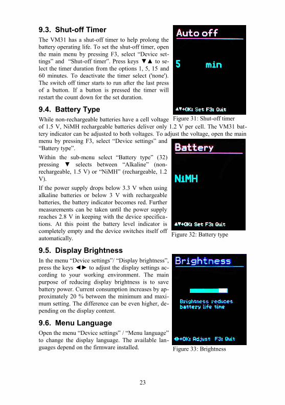
9.1. Sensor CalibrationIf a connected sensor is not TEDS compatible, theVM31 will automatically open the menu “Trans-ducer calibration” (see section 4.2). It can also beopened from the menu “Device settings” to checkor to change the entered sensitivities.
Sensitivities are entered one after another for chan-nels X/Y/Z and, if connected, for channel A. Thesensitivity value is a five-digit number with themeasuring unit mV/ms-2. You find the correct val-ues in the transducer calibration sheet. The decimalpoint can be shifted by pressing F1. The allowedsensitivity range is 0.800 to 12.000 mV/ms-2 or8.00 to 120.00 mV/ms-2.
9.2. Time and DateWhen saving measurement values the date andtime need to be correctly recorded. To set the dateand time, open the main menu by pressing F3 andselect “Device settings”. Within this sub menu se-lect “Date and time”. Using keys ▲▼ you can ad-just the chosen value. Upon reaching the maximumvalue, e.g. in the 23rd hour, the counter starts againfrom the beginning. Press ◄► to skip betweenhour, minute, month, day and year. The date takesaccount of the leap year. It is, however, importantto ensure that no invalid day-month combinationsare entered.
Additionally, clock inaccuracy can be corrected.This can be done using the setting at “Cal.” in ppm(parts per million). The clock frequency can be in-creased with positive values and decreased with negative. The sign changes to minusat +254 ppm.
22
Figure 29: Sensitivity
Figure 30: Time and date
9.3. Shut-off TimerThe VM31 has a shut-off timer to help prolong thebattery operating life. To set the shut-off timer, openthe main menu by pressing F3, select “Device set-tings” and “Shut-off timer”. Press keys ▼▲ to se-lect the timer duration from the options 1, 5, 15 and60 minutes. To deactivate the timer select ('none').The switch off timer starts to run after the last pressof a button. If a button is pressed the timer willrestart the count down for the set duration.
9.4. Battery TypeWhile non-rechargeable batteries have a cell voltageof 1.5 V, NiMH rechargeable batteries deliver only 1.2 V per cell. The VM31 bat-tery indicator can be adjusted to both voltages. To adjust the voltage, open the mainmenu by pressing F3, select “Device settings” and“Battery type”.
Within the sub-menu select “Battery type” (32)pressing ▼ selects between “Alkaline” (non-rechargeable, 1.5 V) or “NiMH” (rechargeable, 1.2V).
If the power supply drops below 3.3 V when usingalkaline batteries or below 3 V with rechargeablebatteries, the battery indicator becomes red. Furthermeasurements can be taken until the power supplyreaches 2.8 V in keeping with the device specifica-tions. At this point the battery level indicator iscompletely empty and the device switches itself offautomatically.
9.5. Display BrightnessIn the menu “Device settings”/ “Display brightness”,press the keys ◄► to adjust the display settings ac-cording to your working environment. The mainpurpose of reducing display brightness is to savebattery power. Current consumption increases by ap-proximately 20 % between the minimum and maxi-mum setting. The difference can be even higher, de-pending on the display content.
9.6. Menu LanguageOpen the menu “Device settings” / “Menu language”to change the display language. The available lan-guages depend on the firmware installed.
23
Figure 31: Shut-off timer
Figure 32: Battery type
Figure 33: Brightness
9.7. Default SettingsIf you would like to reset your VM31 to factory set-tings, open the menu “Device settings” / “Load de-faults” . This will also delete the memory but willnot alter the transducer sensitivities.
10. Reset KeyIf it occurs that the VM31 does not respond to thepress of any key, press the reset key to restart the de-vice. The reset key is reached with a thin objectthrough the aperture next to the type label (35).
Saved data and settings are not lost when the deviceis reset.
11. Connection to a PCThe VM31 has a USB interface. The VM2x-USB cable (36) is connected to theVM31 via its 8 pin connector. Switch the device off before connecting it to the PC.
Connect the other end of the cable to a USB port on the computer and switch theVM31 on again. If the device is being connected with a particular computer for thefirst time, a driver installation will be necessary. The driver MMF_VCP.zip can befound on our website: http://mmf.de/software_download.htm
Unpack and save both driver files in a directory on your computer.
When Windows requests details of the source of the device driver, this directoryshould be entered.
The device driver is digitally signed and runs with Windows XP, Vista, 7 and 8.
24
Figure 36: USB cable VM2x-USB
Figure 35: Reset button
Figure 34: Default settings

12. Data Transfer to a PC
12.1. Opening the Excel File vm31.xlsmThe Excel macro file vm31.xlsm is provided to transfer, display and archive datafrom the VM31. It can be downloaded from http://www.mmf.de/software_down-load.htm. The file runs with all Excel versions starting from Excel 2007.
It transfers the stored data from the connected VM31 memory into Excel tables. Vi -bration exposure A(8) or VDV(8) can be calculated from the human vibrationrecords and measuring reports can be generated. FFT data can also be transferredand displayed graphically.
To work with the file you need to allow macro execution. Click the Office button,then “Excel options”, “Trust center”, “Trust center settings” and “Macro settings”.Either choose “Disable all macros with notification” or “Enable all macros”. Withthe first option you will be asked for permission each time you open the file. Withthe second option Excel will not ask you for permission again, but there is a poten-tial risk of unwanted or dangerous macro codes being executed from other sources.
25
Figure 37: Macro settings in Excel 2010
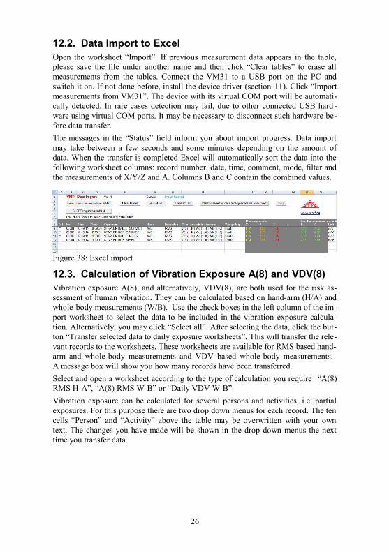
12.2. Data Import to ExcelOpen the worksheet “Import”. If previous measurement data appears in the table,please save the file under another name and then click “Clear tables” to erase allmeasurements from the tables. Connect the VM31 to a USB port on the PC andswitch it on. If not done before, install the device driver (section 11). Click “Importmeasurements from VM31”. The device with its virtual COM port will be automati-cally detected. In rare cases detection may fail, due to other connected USB hard -ware using virtual COM ports. It may be necessary to disconnect such hardware be-fore data transfer.
The messages in the “Status” field inform you about import progress. Data importmay take between a few seconds and some minutes depending on the amount ofdata. When the transfer is completed Excel will automatically sort the data into thefollowing worksheet columns: record number, date, time, comment, mode, filter andthe measurements of X/Y/Z and A. Columns B and C contain the combined values.
12.3. Calculation of Vibration Exposure A(8) and VDV(8)Vibration exposure A(8), and alternatively, VDV(8), are both used for the risk as-sessment of human vibration. They can be calculated based on hand-arm (H/A) andwhole-body measurements (W/B). Use the check boxes in the left column of the im-port worksheet to select the data to be included in the vibration exposure calcula-tion. Alternatively, you may click “Select all”. After selecting the data, click the but-ton “Transfer selected data to daily exposure worksheets”. This will transfer the rele-vant records to the worksheets. These worksheets are available for RMS based hand-arm and whole-body measurements and VDV based whole-body measurements. A message box will show you how many records have been transferred.
Select and open a worksheet according to the type of calculation you require “A(8)RMS H-A”, “A(8) RMS W-B” or “Daily VDV W-B”.
Vibration exposure can be calculated for several persons and activities, i.e. partialexposures. For this purpose there are two drop down menus for each record. The tencells “Person” and “Activity” above the table may be overwritten with your owntext. The changes you have made will be shown in the drop down menus the nexttime you transfer data.
26
Figure 38: Excel import

Click “A(8) calculation” or, in the case of VDV, “Daily exposure calculation” tocalculate the vibration exposure (39). The result(s) will be compared with the limitsstated in the EU directive 2002/44/EC and are displayed in various colors:
black: below exposure action value
purple: between exposure action value and exposure limit
red: above exposure limit
During vibration exposure calculation a report is generated automatically. You canfind it in the worksheet “... Report”. It includes tables with the measured values andthe partial exposure values for each person and activity. Below you will find the vi-bration exposure results for each person (40).
12.4. FFT Data Import to ExcelThe FFT data stored on the VM31 can also be transferred to the Excel macro file.Switch to the worksheet “FFT Import”. If previous FFT data is appears in the table,please save the file under another name and click “Clear FFTs” to clear the table.Then click “Import FFTs from VM31”.
The frequency steps along with the respective amplitudes of X/Y/Z are sorted intotable rows. You will see the date, time and comment for each record. Tick the checkboxes on the left hand side of each record to select which FFTs should be displayedin the three diagrams above the table (Figure 41).
27
Figure 39: Daily exposure calculation in Excel
Figure 40: Example report (part)
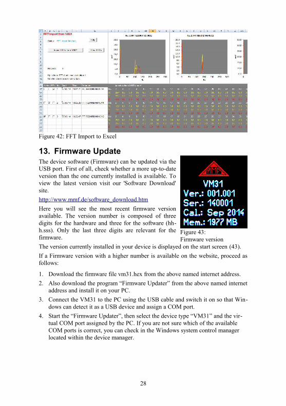
13. Firmware UpdateThe device software (Firmware) can be updated via theUSB port. First of all, check whether a more up-to-dateversion than the one currently installed is available. Toview the latest version visit our 'Software Download'site.
http://www.mmf.de/software_download.htm
Here you will see the most recent firmware versionavailable. The version number is composed of threedigits for the hardware and three for the software (hh-h.sss). Only the last three digits are relevant for thefirmware.
The version currently installed in your device is displayed on the start screen (43).
If a Firmware version with a higher number is available on the website, proceed asfollows:
1. Download the firmware file vm31.hex from the above named internet address.
2. Also download the program “Firmware Updater” from the above named internetaddress and install it on your PC.
3. Connect the VM31 to the PC using the USB cable and switch it on so that Win-dows can detect it as a USB device and assign a COM port.
4. Start the “Firmware Updater”, then select the device type “VM31” and the vir-tual COM port assigned by the PC. If you are not sure which of the available COM ports is correct, you can check in the Windows system control manager located within the device manager.
28
Figure 42: FFT Import to Excel
Figure 43: Firmware version
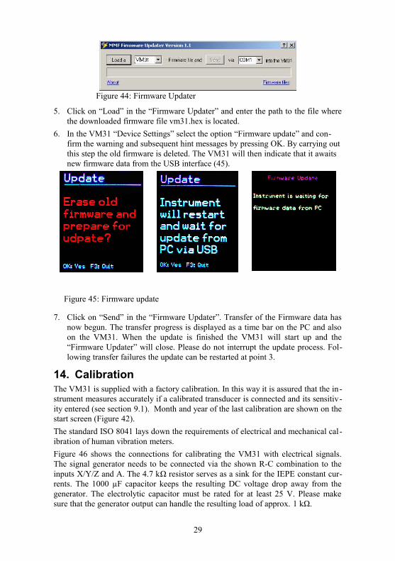
5. Click on “Load” in the “Firmware Updater” and enter the path to the file wherethe downloaded firmware file vm31.hex is located.
6. In the VM31 “Device Settings” select the option “Firmware update” and con-firm the warning and subsequent hint messages by pressing OK. By carrying outthis step the old firmware is deleted. The VM31 will then indicate that it awaits new firmware data from the USB interface (45).
Figure 45: Firmware update
7. Click on “Send” in the “Firmware Updater”. Transfer of the Firmware data hasnow begun. The transfer progress is displayed as a time bar on the PC and alsoon the VM31. When the update is finished the VM31 will start up and the“Firmware Updater” will close. Please do not interrupt the update process. Fol-lowing transfer failures the update can be restarted at point 3.
14. CalibrationThe VM31 is supplied with a factory calibration. In this way it is assured that the in-strument measures accurately if a calibrated transducer is connected and its sensitiv-ity entered (see section 9.1). Month and year of the last calibration are shown on thestart screen (Figure 42).
The standard ISO 8041 lays down the requirements of electrical and mechanical cal-ibration of human vibration meters.
Figure 46 shows the connections for calibrating the VM31 with electrical signals.The signal generator needs to be connected via the shown R-C combination to theinputs X/Y/Z and A. The 4.7 kΩ resistor serves as a sink for the IEPE constant cur-rents. The 1000 µF capacitor keeps the resulting DC voltage drop away from thegenerator. The electrolytic capacitor must be rated for at least 25 V. Please makesure that the generator output can handle the resulting load of approx. 1 kΩ.
29
Figure 44: Firmware Updater

Plug for X/Y/Z: Binder 711 series, 4 pins, order no. 99-0079-100-04Plug for A: Binder 711 series, 8 pins, order no. 99-0479-100-08
The maximum input voltage without overload indication is ± 1150 mV.
30
Figure 46: Connections for electrical calibration
GNDX Y
Z
+
4k7
1000µ
GeneratorGND
X
+
4k7
1000µ
GND
Y
+
4k7
1000µ
GND
Z
+
4k7
1000µ
GND
A
GND
A
15. Technical DataInputs 4 Low-power IEPE inputs, > 0.7 mA / 17 V,
transducer sensitivity range 0.8 to 120 mV/ms-2
TEDS support for template 25 to IEEE 1451.4
Display functions Human vibration
General vibration (acceleration / velocity / displacement)
Interval RMSVector sumMaximum running RMS (MTVV)Vibration dose value (VDV)Running RMSMaximum running RMSVector sumPeak valueMaximum peak value
Measuring ranges Acceleration Velocity Displacement(zero-to-peak values)
Sensor with 1 mV/ms-2
1100 m/s²100 - 10 000 mm/s (1 kHz /1 Hz)250 - 15 000 µm (5 Hz / 250 Hz)
Sensor with 10 mV/ms-2
110 m/s²10 - 1000 mm/s (1 kHz /1 Hz)25 - 1500 µm (5 Hz / 250 Hz)
Display resolution Acceleration Velocity Displacement
Sensor with 1 / 10 mV/ms-2
0.01 m/s²0.1 mm/s1 µm
Sensor with 100 mV/ms-2
0.001 m/s²0.001 mm/s0.1 µm
Linearity range > 75 dB (for < ± 6 % error)
Noise < 0,003 m/s²
Filters Human vibration
Acceleration Velocity Displacement
Weighting filters Wb, Wc, Wd, Wh, Wj, Wk, WmUnweighted: 6.3 - 1259 Hz (hand-arm); 0.4 - 100 Hz (whole-body)0.1 Hz – 2 kHz; 1 Hz – 1 kHz1 Hz – 100 Hz; 2 Hz – 1 kHz; 10 Hz – 1 kHz5 Hz: – 250 Hz
Frequency analysis 125 line FFT for X/Y/Z; Peak spectrum of accelerationFrequency ranges: 3 - 240, 6 - 480, 12 - 960, 24 - 1920 HzRefresh rate: 0,5/s; Windowing: Hann
Data memory Flash; 10 000 measurements; 1000 FFTs
Display OLED, colored, 128×160 pixels
USB interface USB 2.0, full-speed, CDC mode, via cable VM2x-USB
Batteries 3 cells size AAA or Alkaline (LR03) or rechargeable NiMH (HR03)
Battery oper. time 10 - 14 hours
Oper. temperature - 20 – 60 °C
Dimensions 125 mm x 65 mm x 27 mm (without connectors)
Weight 140 g (with batteries, without sensor)
31

Limited Warranty
Metra warranties that for a period of
24 months
its products will be free from manufacturing or material defects
and shall conform to the specifications current at the time of shipment.
The warranty period starts from the date of invoice.
The customer must provide the dated bill of sale as evidence.
The warranty period ends after 24 months. Repairs do not extend the warranty period.
This limited warranty only covers defects which arise as a result
of normal use according to the instruction manual.
Metra’s responsibility under this warranty does not apply to any
improper or inadequate maintenance or modification
and operation outside the product’s specifications.
Shipment to Metra will be paid by the customer.The repaired or replaced product will be sent back at Metra’s expense.
Declaration of ConformityProduct: Vibration Meter
Type: VM31
We hereby certified that the above mentioned products comply with the demands pursuant tothe following standards
EN 61010-1: 2002 (Safety requirements)EN 61326-1: 2006 (EMC requirements)
The producer responsible for this declaration is
Metra Mess- und Frequenztechnik in Radebeul e.K.
Meißner Str. 58, D-01445 Radebeul
Declared by
Michael Weber
Radebeul,
32


![Vibration Energy Harvesting: Machinery Vibration, …...Vibration Energy Harvesting: Machinery Vibration, Human Move ment and Flow Induced Vibration 27 r ma P 4]Z 2 (3) where a Y Z2](https://img.pdfslide.net/doc/110x75/5e7c70af07fbe24a6e769fc0/vibration-energy-harvesting-machinery-vibration-vibration-energy-harvesting.jpg)