Embed Size (px)
Citation preview
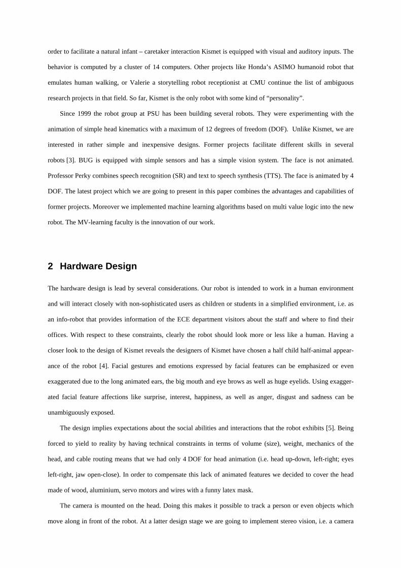
A Humanoid Robot based on Machine Learning with Incorporation of Vision and Speech Recognition
Stefan Gebauer+, Marek A. Perkowski*
+Department of Electrical Engineering, Chemniz University of Technology, Reichenhainer Str. 70, D-09107
Chemnitz, Germany, [email protected]; * Department of Electrical and Computer Engineering, Portland State University, 1900 SW 4th Avenue, Portland,
OR 97201, USA, [email protected]
Abstract This paper describes the progress in our project “building a humanoid” robot. There are several approaches by
groups that experimented with humanoid robots. Basically, they used common algorithms, which have been
known for many years, and very well designed mechanics for sophisticated animation. However, this approach
uses rather simple mechanics. The focus is on software development for computer vision, speech recognition and
machine learning. For years Multi Value Decomposition has been successfully developed for circuit
optimization. Showing that these algorithms can also be adapted to machine learning, the goal will be to
demonstrate relational decomposition as a new general purpose machine learning method. Finally, we hope to
contribute a new way of thinking to the classical learning methods such as Neuronal Networks and
Reinforcement Learning. Keywords: Machine Learning, MVSIS, MV-Decomposition, TTS, SR, Robot, computer vision
1 Introduction
In the imagination of humans there were always intelligent machines. The actual meaning of the word robot was
derived from the Czech word robota which can be translated as “forced worker”. It was created by Karel Capek
who needed a term for an intelligent machine in his play R.U.R (Rossum’s Universal Robots) produced in 1921.
Some of the ideas that used to be science fiction for a long time have become reality nowadays. As a matter of
fact, industrial robots have been successfully introduced to many fabrication processes. However, robots that
work in human environments are rare if there are any at all. Today, there is no doubt that the use of humanoid
robots will become common in the future. The question arises how they should look like. The design has to be
quite different from the industrial colleagues. Since they have to interact with humans and cope with the human
environment, their appearance will be close to that of humans (“humanoid robot”). The most famous contribu-
tion in this relatively new field was made by C. Brezeal from MIT [1, 2]. She created Kismet, an expressive
humanoid robot head with perceptual and motor modalities tailored to behave like a seven years old child. In
order to facilitate a natural infant – caretaker interaction Kismet is equipped with visual and auditory inputs. The
behavior is computed by a cluster of 14 computers. Other projects like Honda’s ASIMO humanoid robot that
emulates human walking, or Valerie a storytelling robot receptionist at CMU continue the list of ambiguous
research projects in that field. So far, Kismet is the only robot with some kind of “personality”.
Since 1999 the robot group at PSU has been building several robots. They were experimenting with the
animation of simple head kinematics with a maximum of 12 degrees of freedom (DOF). Unlike Kismet, we are
interested in rather simple and inexpensive designs. Former projects facilitate different skills in several
robots [3]. BUG is equipped with simple sensors and has a simple vision system. The face is not animated.
Professor Perky combines speech recognition (SR) and text to speech synthesis (TTS). The face is animated by 4
DOF. The latest project which we are going to present in this paper combines the advantages and capabilities of
former projects. Moreover we implemented machine learning algorithms based on multi value logic into the new
robot. The MV-learning faculty is the innovation of our work.
2 Hardware Design
The hardware design is lead by several considerations. Our robot is intended to work in a human environment
and will interact closely with non-sophisticated users as children or students in a simplified environment, i.e. as
an info-robot that provides information of the ECE department visitors about the staff and where to find their
offices. With respect to these constraints, clearly the robot should look more or less like a human. Having a
closer look to the design of Kismet reveals the designers of Kismet have chosen a half child half-animal appear-
ance of the robot [4]. Facial gestures and emotions expressed by facial features can be emphasized or even
exaggerated due to the long animated ears, the big mouth and eye brows as well as huge eyelids. Using exagger-
ated facial feature affections like surprise, interest, happiness, as well as anger, disgust and sadness can be
unambiguously exposed.
The design implies expectations about the social abilities and interactions that the robot exhibits [5]. Being
forced to yield to reality by having technical constraints in terms of volume (size), weight, mechanics of the
head, and cable routing means that we had only 4 DOF for head animation (i.e. head up-down, left-right; eyes
left-right, jaw open-close). In order to compensate this lack of animated features we decided to cover the head
made of wood, aluminium, servo motors and wires with a funny latex mask.
The camera is mounted on the head. Doing this makes it possible to track a person or even objects which
move along in front of the robot. At a latter design stage we are going to implement stereo vision, i.e. a camera
mounted within the pupil of each eye. One of the drawbacks is the higher computational performance necessary
to assess vision data and therefore the Frank project works with a single camera. We installed several inexpen-
sive servos from Hitec and Futaba to animate the robot. A number of 13 servos in total have been used to
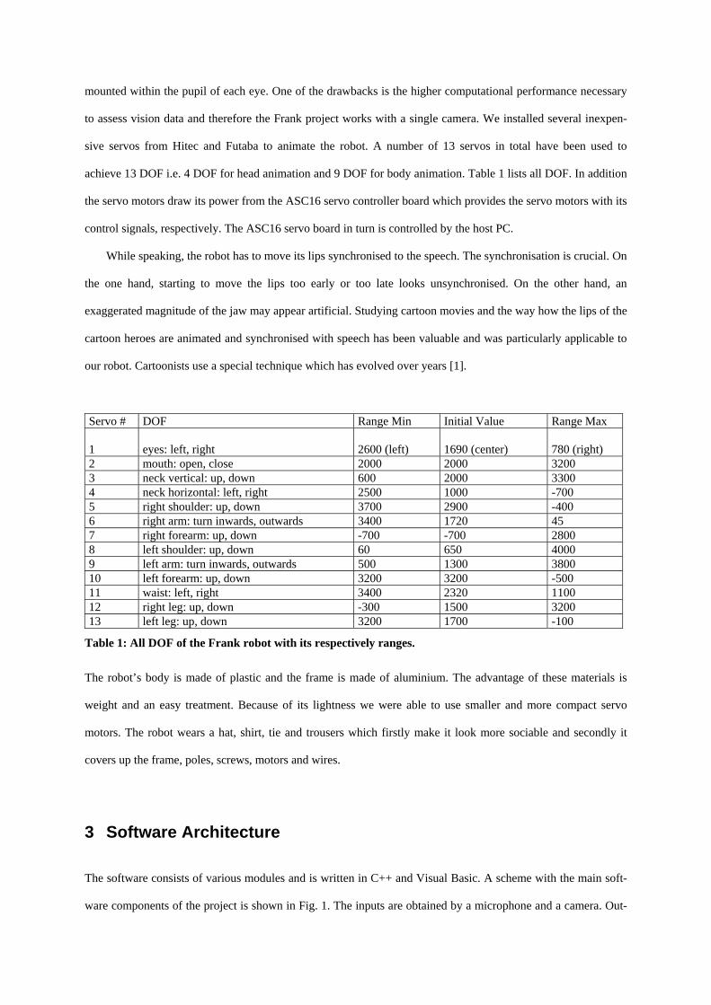
achieve 13 DOF i.e. 4 DOF for head animation and 9 DOF for body animation. Table 1 lists all DOF. In addition
the servo motors draw its power from the ASC16 servo controller board which provides the servo motors with its
control signals, respectively. The ASC16 servo board in turn is controlled by the host PC.
While speaking, the robot has to move its lips synchronised to the speech. The synchronisation is crucial. On
the one hand, starting to move the lips too early or too late looks unsynchronised. On the other hand, an
exaggerated magnitude of the jaw may appear artificial. Studying cartoon movies and the way how the lips of the
cartoon heroes are animated and synchronised with speech has been valuable and was particularly applicable to
our robot. Cartoonists use a special technique which has evolved over years [1].
Servo # DOF Range Min Initial Value Range Max 1
eyes: left, right
2600 (left)
1690 (center)
780 (right)
2 mouth: open, close 2000 2000 3200 3 neck vertical: up, down 600 2000 3300 4 neck horizontal: left, right 2500 1000 -700 5 right shoulder: up, down 3700 2900 -400 6 right arm: turn inwards, outwards 3400 1720 45 7 right forearm: up, down -700 -700 2800 8 left shoulder: up, down 60 650 4000 9 left arm: turn inwards, outwards 500 1300 3800 10 left forearm: up, down 3200 3200 -500 11 waist: left, right 3400 2320 1100 12 right leg: up, down -300 1500 3200 13 left leg: up, down 3200 1700 -100
Table 1: All DOF of the Frank robot with its respectively ranges.
The robot’s body is made of plastic and the frame is made of aluminium. The advantage of these materials is
weight and an easy treatment. Because of its lightness we were able to use smaller and more compact servo
motors. The robot wears a hat, shirt, tie and trousers which firstly make it look more sociable and secondly it
covers up the frame, poles, screws, motors and wires.
3 Software Architecture
The software consists of various modules and is written in C++ and Visual Basic. A scheme with the main soft-
ware components of the project is shown in Fig. 1. The inputs are obtained by a microphone and a camera. Out-
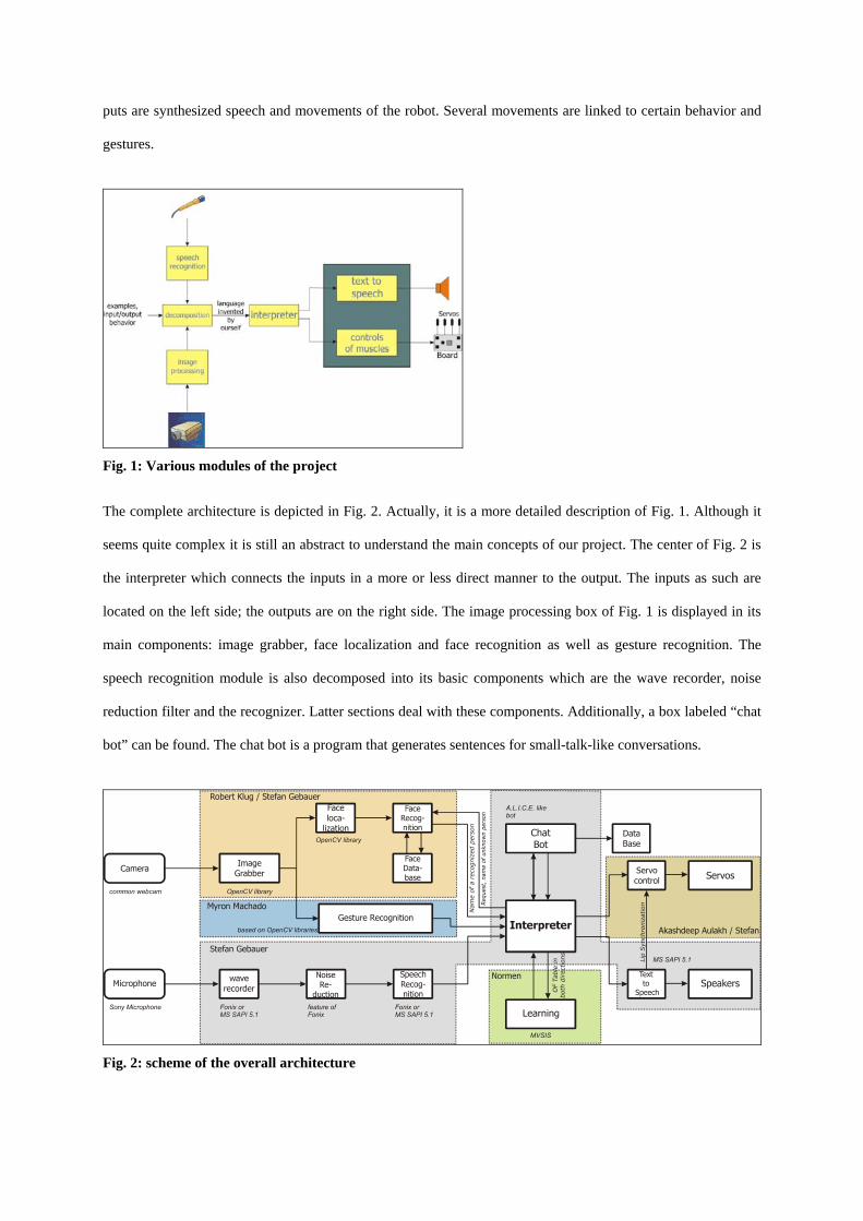
puts are synthesized speech and movements of the robot. Several movements are linked to certain behavior and
gestures.
Fig. 1: Various modules of the project
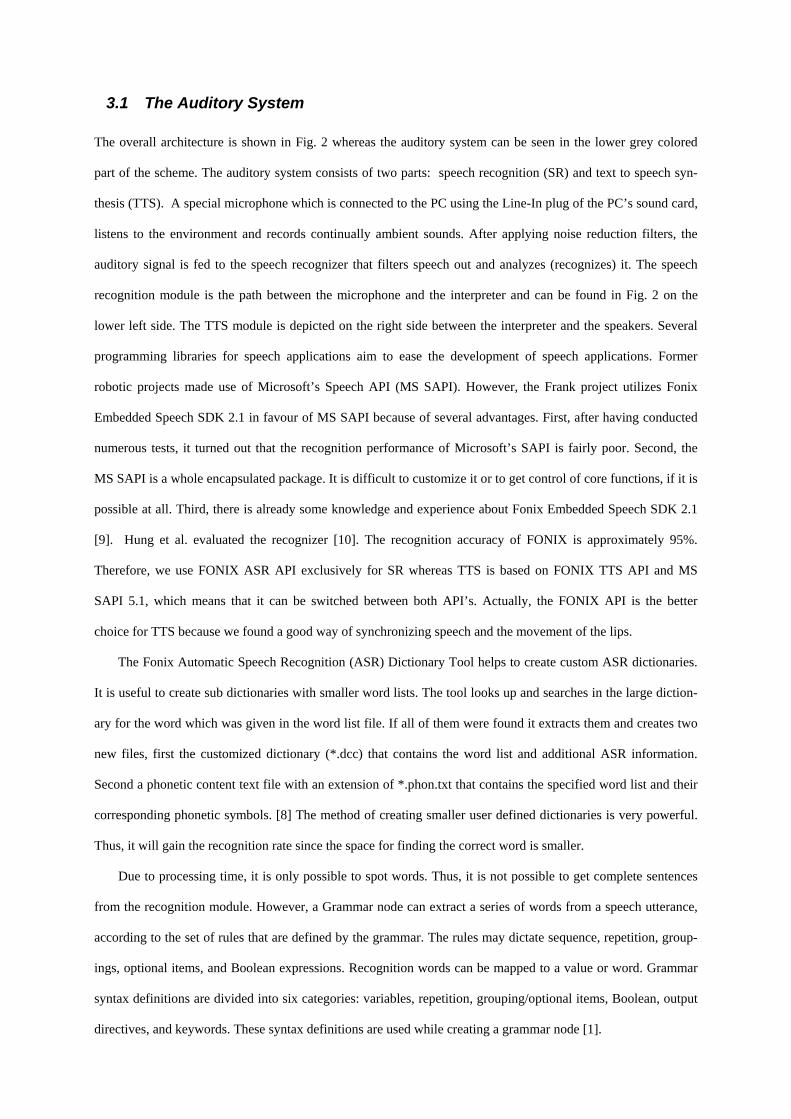
The complete architecture is depicted in Fig. 2. Actually, it is a more detailed description of Fig. 1. Although it
seems quite complex it is still an abstract to understand the main concepts of our project. The center of Fig. 2 is
the interpreter which connects the inputs in a more or less direct manner to the output. The inputs as such are
located on the left side; the outputs are on the right side. The image processing box of Fig. 1 is displayed in its
main components: image grabber, face localization and face recognition as well as gesture recognition. The
speech recognition module is also decomposed into its basic components which are the wave recorder, noise
reduction filter and the recognizer. Latter sections deal with these components. Additionally, a box labeled “chat
bot” can be found. The chat bot is a program that generates sentences for small-talk-like conversations.
Fig. 2: scheme of the overall architecture
3.1 The Auditory System The overall architecture is shown in Fig. 2 whereas the auditory system can be seen in the lower grey colored
part of the scheme. The auditory system consists of two parts: speech recognition (SR) and text to speech syn-
thesis (TTS). A special microphone which is connected to the PC using the Line-In plug of the PC’s sound card,
listens to the environment and records continually ambient sounds. After applying noise reduction filters, the
auditory signal is fed to the speech recognizer that filters speech out and analyzes (recognizes) it. The speech
recognition module is the path between the microphone and the interpreter and can be found in Fig. 2 on the
lower left side. The TTS module is depicted on the right side between the interpreter and the speakers. Several
programming libraries for speech applications aim to ease the development of speech applications. Former
robotic projects made use of Microsoft’s Speech API (MS SAPI). However, the Frank project utilizes Fonix
Embedded Speech SDK 2.1 in favour of MS SAPI because of several advantages. First, after having conducted
numerous tests, it turned out that the recognition performance of Microsoft’s SAPI is fairly poor. Second, the
MS SAPI is a whole encapsulated package. It is difficult to customize it or to get control of core functions, if it is
possible at all. Third, there is already some knowledge and experience about Fonix Embedded Speech SDK 2.1
[9]. Hung et al. evaluated the recognizer [10]. The recognition accuracy of FONIX is approximately 95%.
Therefore, we use FONIX ASR API exclusively for SR whereas TTS is based on FONIX TTS API and MS
SAPI 5.1, which means that it can be switched between both API’s. Actually, the FONIX API is the better
choice for TTS because we found a good way of synchronizing speech and the movement of the lips.
The Fonix Automatic Speech Recognition (ASR) Dictionary Tool helps to create custom ASR dictionaries.
It is useful to create sub dictionaries with smaller word lists. The tool looks up and searches in the large diction-
ary for the word which was given in the word list file. If all of them were found it extracts them and creates two
new files, first the customized dictionary (*.dcc) that contains the word list and additional ASR information.
Second a phonetic content text file with an extension of *.phon.txt that contains the specified word list and their
corresponding phonetic symbols. [8] The method of creating smaller user defined dictionaries is very powerful.
Thus, it will gain the recognition rate since the space for finding the correct word is smaller.
Due to processing time, it is only possible to spot words. Thus, it is not possible to get complete sentences
from the recognition module. However, a Grammar node can extract a series of words from a speech utterance,
according to the set of rules that are defined by the grammar. The rules may dictate sequence, repetition, group-
ings, optional items, and Boolean expressions. Recognition words can be mapped to a value or word. Grammar
syntax definitions are divided into six categories: variables, repetition, grouping/optional items, Boolean, output
directives, and keywords. These syntax definitions are used while creating a grammar node [1].
Let me show an example for creating a grammar node for a receptionist at university. Creating a grammar node
is a kind of solving a story problem. For example, one could ask for directions or could inquire for faculty staff.
For simplicity, say someone asks for directions to find room 155 and the office in the ECE building. Another
person asks for Prof. Morris and Prof. Perkowski.
The word sets then look like: inquire set: where, is, looking for Person set: Dr. Morris, Dr. Perkowski location set: Office, 155 Now, the word sets have to be assigned to a variable. It is a sort of pruning the space. For each variable, there are only a few possibilities. Note: I introduce more possibilities for saying 155: $inquire = where is looking for; $person = Morris Perkowski; $location = office 155 one fifty five one hundred fifty five; The relationship between the words in a group must be expressed in terms of Boolean relationships. There are two Boolean characters defined, OR (|), AND (a space): $inquire = where | is | looking for; $person = Morris | Perkowski; $location = office | 155 | one fifty five | one hundred fifty five; In some cases it may be useful to assign to the output another word than the recognized output. In the case above I do it with “one fifty five” and “one hundred fifty five” both are the same number 155: $inquire = where | is | looking for; $person = Morris | Perkowski; $location = office | 155 | one fifty five%155 | one hundred fifty five%155; Finally, the grammar sequence has to be created. A person who’s looking for Prof. Morris or Prof. Perkowski could ask the following sentences: Where is Prof. Perkowski? Is Prof. Morris in his office? I’m looking for Prof. Perkowski. Do you know where Prof. Morris is? Hence the grammar of those sentences may have the following structure: $grammar = $inquire $person [$location]. The last variable is in brackets. This indicates location is optional which makes sense because not every sentence has a location word in the question. The same can be applied to the direction questions like. Where can I find room 155? Where is the ECE Office? $grammar = $inquire $location.
Once again, grammar nodes allow the usage of much smaller customized sub dictionaries that increase recogni-
tion performance in terms of speed and accuracy. Due to the fact that smaller databases are browsed within
shorter scanning time recognition is faster.
Because of the limited entries of the dictionary or the words are pronounced not well enough, the recogni-
tion fails from time to time. We believe a non-predictable robot is much more interesting than one that perma-
nently repeats utterances and phrases. Therefore, a kind of randomness has been added to the dialogs. The robot
answers questions or topics that the robot does not have in its database randomly and nonsensically. Instead of
using continuously tiring sentences like “Can you repeat what you just said?”, “I didn’t get you, please repeat?”,
“What do you mean?” etc., that interrupt the flow of a conversation, we designed the robot in such a way that it
asks only once. If it is still impossible to obtain a meaningful topic from the robot’s database, a sentence will be
generated that is not based on what has been previously said. We observed that this behavior can be very funny
in some occasions. Sometimes people try to understand it i.e. they look for a reason why the robot acts like this.
It may appear to the one or the other that the robot does not want to speak about certain topics. However, this
process is not driven by any heuristics.
3.2 Vision System The robot’s vision consists of a commercial web cam which is connected to the host PC by USB. The entire vi-
sion system is based on OpenCV, an image processing library aimed at real time computer vision. The imple-
mented Hidden Markov Model (HMM) algorithm facilitates gesture recognition and face recognition. Both
modules, gesture recognition and face recognition, are fed with image data by a single web cam. The images
which are continuously taken by the camera are stored in the proprietary image format of OpenCV IPL-image.
Grabbing image data for the web cam is incorporated using DirectX 9.0b. Available data are analyzed by both
image processing modules simultaneously.
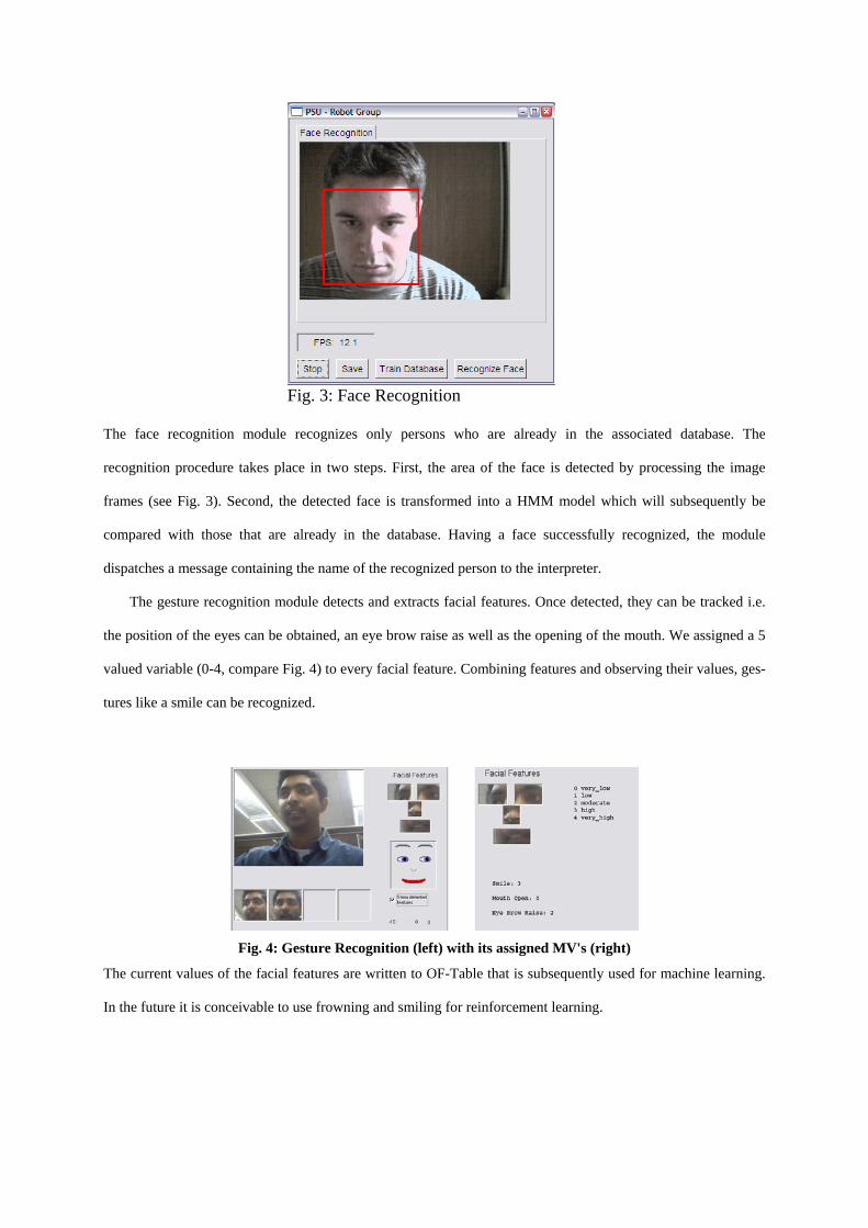
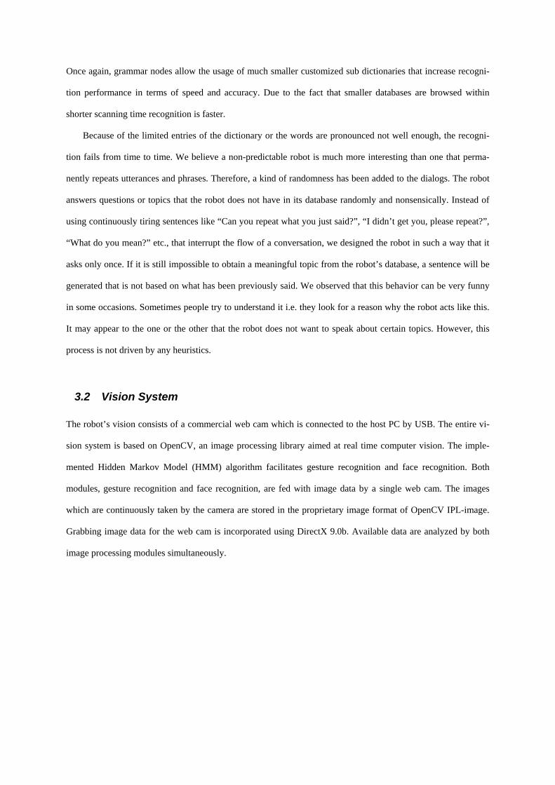
Fig. 3: Face Recognition
The face recognition module recognizes only persons who are already in the associated database. The
recognition procedure takes place in two steps. First, the area of the face is detected by processing the image
frames (see Fig. 3). Second, the detected face is transformed into a HMM model which will subsequently be
compared with those that are already in the database. Having a face successfully recognized, the module
dispatches a message containing the name of the recognized person to the interpreter.
The gesture recognition module detects and extracts facial features. Once detected, they can be tracked i.e.
the position of the eyes can be obtained, an eye brow raise as well as the opening of the mouth. We assigned a 5
valued variable (0-4, compare Fig. 4) to every facial feature. Combining features and observing their values, ges-
tures like a smile can be recognized.
Fig. 4: Gesture Recognition (left) with its assigned MV's (right)
The current values of the facial features are written to OF-Table that is subsequently used for machine learning.
In the future it is conceivable to use frowning and smiling for reinforcement learning.
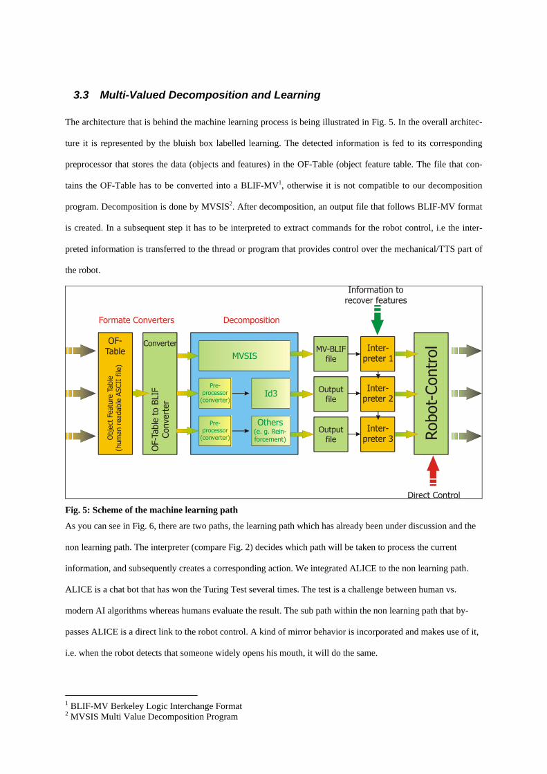
3.3 Multi-Valued Decomposition and Learning The architecture that is behind the machine learning process is being illustrated in Fig. 5. In the overall architec-
ture it is represented by the bluish box labelled learning. The detected information is fed to its corresponding
preprocessor that stores the data (objects and features) in the OF-Table (object feature table. The file that con-
tains the OF-Table has to be converted into a BLIF-MV1, otherwise it is not compatible to our decomposition
program. Decomposition is done by MVSIS2. After decomposition, an output file that follows BLIF-MV format
is created. In a subsequent step it has to be interpreted to extract commands for the robot control, i.e the inter-
preted information is transferred to the thread or program that provides control over the mechanical/TTS part of
the robot.
Fig. 5: Scheme of the machine learning path
As you can see in Fig. 6, there are two paths, the learning path which has already been under discussion and the
non learning path. The interpreter (compare Fig. 2) decides which path will be taken to process the current
information, and subsequently creates a corresponding action. We integrated ALICE to the non learning path.
ALICE is a chat bot that has won the Turing Test several times. The test is a challenge between human vs.
modern AI algorithms whereas humans evaluate the result. The sub path within the non learning path that by-
passes ALICE is a direct link to the robot control. A kind of mirror behavior is incorporated and makes use of it,
i.e. when the robot detects that someone widely opens his mouth, it will do the same.
1 BLIF-MV Berkeley Logic Interchange Format 2 MVSIS Multi Value Decomposition Program
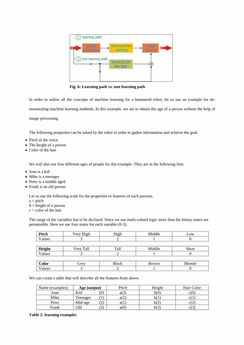
Fig. 6: Learning path vs. non learning path
In order to utilize all the concepts of machine learning for a humanoid robot, let us use an example for de-
monstrating machine learning methods. In this example, we are to obtain the age of a person without the help of
image processing.
The following properties can be asked by the robot in order to gather information and achieve the goal.
• Pitch of the voice • The height of a person • Color of the hair
We will also use four different ages of people for this example. They are in the following lists:
• Joan is a kid • Mike is a teenager • Peter is a middle aged • Frank is an old person
Let us use the following scale for the properties or features of each persons. a = pitch b = height of a person c = color of the hair The range of the variables has to be declared. Since we use multi-valued logic more than the binary states are permissible. Here we use four states for each variable (0-3).
Pitch Very High High Middle Low Values 3 2 1 0
Height Very Tall Tall Middle Short Values 3 2 1 0
Color Grey Black Brown Blonde Values 3 2 1 0
We can create a table that will describe all the features from above.
Name (examples) Age (output) Pitch Height Hair Color Joan Kid (0) a(3) b(0) c(0) Mike Teenager (1) a(2) b(1) c(1) Peter Mid-age (2) a(1) b(2) c(2) Frank Old (3) a(0) b(3) c(3)
Table 2: learning examples
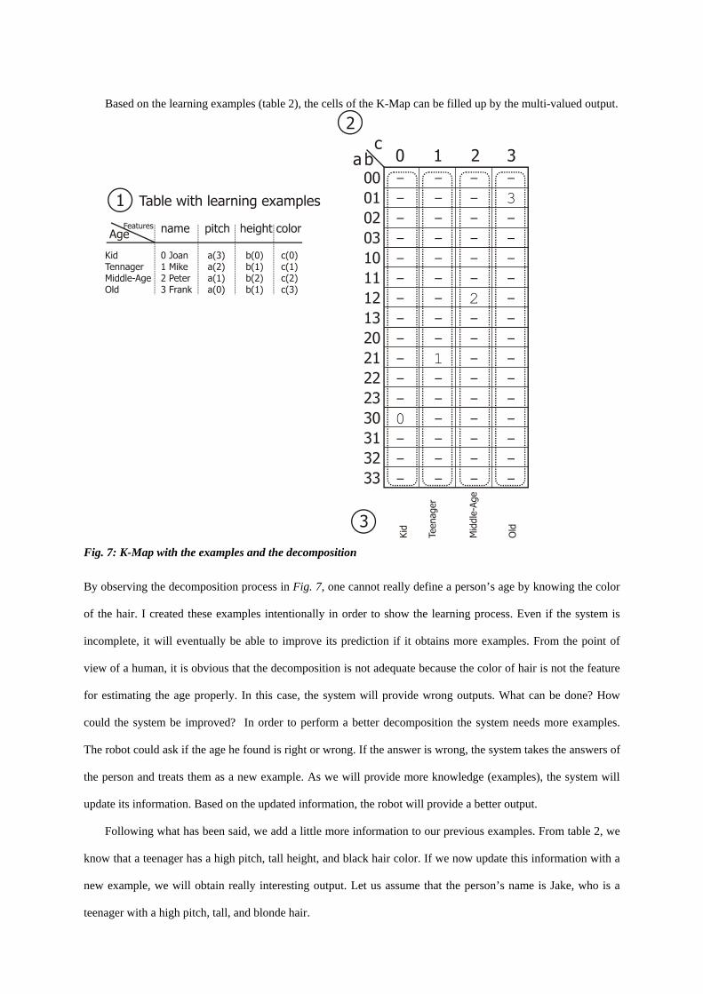
Based on the learning examples (table 2), the cells of the K-Map can be filled up by the multi-valued output.
Fig. 7: K-Map with the examples and the decomposition
By observing the decomposition process in Fig. 7, one cannot really define a person’s age by knowing the color
of the hair. I created these examples intentionally in order to show the learning process. Even if the system is
incomplete, it will eventually be able to improve its prediction if it obtains more examples. From the point of
view of a human, it is obvious that the decomposition is not adequate because the color of hair is not the feature
for estimating the age properly. In this case, the system will provide wrong outputs. What can be done? How
could the system be improved? In order to perform a better decomposition the system needs more examples.
The robot could ask if the age he found is right or wrong. If the answer is wrong, the system takes the answers of
the person and treats them as a new example. As we will provide more knowledge (examples), the system will
update its information. Based on the updated information, the robot will provide a better output.
Following what has been said, we add a little more information to our previous examples. From table 2, we
know that a teenager has a high pitch, tall height, and black hair color. If we now update this information with a
new example, we will obtain really interesting output. Let us assume that the person’s name is Jake, who is a
teenager with a high pitch, tall, and blonde hair.

Age Name Pitch Height Hair Color
Teenager (1) Jake 2 1 0 A new Karnaught map based on our updated information can be drawn.
Fig. 8: modified K-Map
From the K-Map in Fig. 1, our system will define a person’s age by knowing the pitch. It seems this is a better
decomposition due to the fact that the pitch changes with age. It is amazing that we obtain a good result after 5
examples. The more (true) examples the system collects the better the decomposition. On the other hand, it is not
essential to have many examples to obtain good decomposition results. In most cases it is enough to have some
more variables for a reasonable reasoning.
MVSIS does all decomposition work in the background. I will only give a brief overview about the BLIF-
MV file format. It is of interest to understand how MVSIS works. In the following only commands are discussed
which are valid for our project. BLIF (Berkeley Logic Interchange Format) is used to describe circuits in text
format. Several logic minimization programs use it as input and output file format. Later on, it was enhanced to
MV variables. BLIF-MV is a language designed for describing hierarchical sequential systems with non-
determinism [7]. It is possible to describe systems hierarchically due to the ability to describe systems
sequentially. Therefore, the implementation of non-deterministic behaviors is possible. This is done by allowing
non-deterministic gates in descriptions. Non-deterministic gates generate an output arbitrarily from the set of
pre-specified outputs. Another extension of the BLIF-MV format is the support of multi-valued variables.
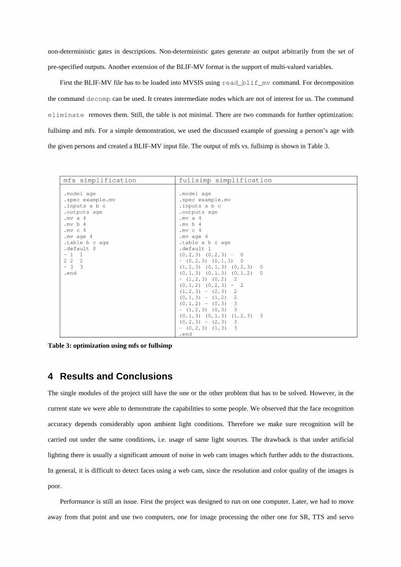
First the BLIF-MV file has to be loaded into MVSIS using read_blif_mv command. For decomposition
the command decomp can be used. It creates intermediate nodes which are not of interest for us. The command
eliminate removes them. Still, the table is not minimal. There are two commands for further optimization:
fullsimp and mfs. For a simple demonstration, we used the discussed example of guessing a person’s age with
the given persons and created a BLIF-MV input file. The output of mfs vs. fullsimp is shown in Table 3.
mfs simplification fullsimp simplification .model age .spec example.mv .inputs a b c .outputs age .mv a 4 .mv b 4 .mv c 4 .mv age 4 .table b c age .default 0 - 1 1 2 2 2 - 3 3 .end
.model age .spec example.mv .inputs a b c .outputs age .mv a 4 .mv b 4 .mv c 4 .mv age 4 .table a b c age .default 1 (0,2,3) (0,2,3) - 0 - (0,2,3) (0,1,3) 0 (1,2,3) (0,1,3) (0,2,3) 0 (0,1,3) (0,1,3) (0,1,2) 0 - (1,2,3) (0,2) 2 (0,1,2) (0,2,3) - 2 (1,2,3) - (2,3) 2 (0,1,3) - (1,2) 2 (0,1,2) - (0,3) 3 - (1,2,3) (0,3) 3 (0,1,3) (0,1,3) (1,2,3) 3 (0,2,3) - (2,3) 3 - (0,2,3) (1,3) 3 .end
Table 3: optimization using mfs or fullsimp
4 Results and Conclusions The single modules of the project still have the one or the other problem that has to be solved. However, in the
current state we were able to demonstrate the capabilities to some people. We observed that the face recognition
accuracy depends considerably upon ambient light conditions. Therefore we make sure recognition will be
carried out under the same conditions, i.e. usage of same light sources. The drawback is that under artificial
lighting there is usually a significant amount of noise in web cam images which further adds to the distractions.
In general, it is difficult to detect faces using a web cam, since the resolution and color quality of the images is
poor.
Performance is still an issue. First the project was designed to run on one computer. Later, we had to move
away from that point and use two computers, one for image processing the other one for SR, TTS and servo
control. Up to now, the standard recognition routines have integrated only. There are optimization methods
available but this means in essence a reduced complexity of the neural nets.
We used invented games and situations to evaluate the machine learning method. It does not work completely
independently since there is no artificial intelligence that determines that this particular situation is interesting
and has to be analyzed using machine learning. As a result we decide when to use machine learning and in which
situations.
Improving the learning behavior also means to improve the perceptual system of the robot. The sensor data
are the input for MVSIS. The more inputs the better the results. The question arises where to obtain more data?
The vision system has the broadest potential. Stereo vision could improve face and gesture recognition.
Determining the distance to objects will be possible as well.
5 Acknowledgements
First of all, I would like to thank Prof. Perkowski for various valuable ideas. Special thanks to Robert Klug and
Myron Machado for their contribution to the vision system, Akashdeep Singh Aulakh who invented some
interactive games that one can play with the robot and last but not least to Normen Giesecke who helped with
MVSIS and did valuable programming work.
6 References
[1] Cynthia C. Breazeal, “Designing Sociable Robots”, The MIT Press, 2002 [2] C. Breazeal, Sociable Machines: Expressive Social Exchange Between Humans and Robots, Ph.D. Thesis, MIT, 2000. [3] Marek Perkowski, Tsutomu Sasao, Atsumu Iseno, Uland Wong, Mikhail Pivtoraiko, Michele Folgheraiter, Martin Lukac, David Ng, Miranda Fix and Karl Kuchs, ``Use
of Machine Learning based on Constructive Induction in Dialogs with Robotic Heads,'' Proceedings of ICORR 2003 (the 8th International Conference on Rehabilitation Robotics), April 22-25, 2003, KAIST, Korea. pp. 326 -- 329.
[4] C. Breazeal and B. Scasselati, Infant-like social interactions between a robot and a Human caretaker, In Adaptive Behavior, August 2000. [6] A. Edsinger and U-M. O’Reilly, “Designing a Humanoid Robot Face to Fulfill a
Social Contract”, MIT Memo, 2002 [7] Uland Wong and Marek Perkowski, “A new Approach to Robot’s Imitations of Behaviors by Decomposition of Multiple-Valued Relations”, paper,
Portland, OR, 2002 [8] FONIX Embedded Speech SDK 2.1 ASR Help, 2002 [9] Hung Nguyen, Phuong Than and Honghuong Nguyen, “External Design Documentation of Direction Software Version 1.1”, Portland, OR, winter 2003 [10] Hung Nguyen, “Speech Recognition Report – Fonix Product Evaluation”, Portland, OR, winter 2003