Embed Size (px)
Citation preview
Humanoid Self-correction of Posture Using a Mirror
Naohiro Hayashi, Tetsuo Tomizawa, Takashi Suehiro and Shunsuke Kudoh
Abstract— Humanoid robots have discrepancies between thepostures simulated on models and those of actual humanoidbodies. To correct this problem, this paper proposes a methodin which a robot observes its own posture in a mirror. Thismethod does not need an additional time-consuming setup, suchas calibration of external cameras. We attach a reference pointto a known position on the robot body. By observing markersand the reference point in the same view, we can estimatethe position of the markers accurately based on the geometricrelationship between the mirror, an object, and its mirrorreflection. We evaluate the proposed method by experimentsof measuring and correcting the posture of an actual robotbody to attain the target posture.
Index Terms— Humanoid robot, mirror, Posture correction.
I. INTRODUCTION
It is common practice to use a simulator to design the
motion of a humanoid robot and then import the design into
the robot. Discrepancies appearing between the postures of
the simulated model and the actual robot lead to serious
problems in controlling the robot. In practice, we observe
differences caused by backlash, transmission errors in the
gears, and warping of the body due to gravity (Fig. 1). A
method for reducing such discrepancies is important in order
to accurately control humanoid robots.
This paper proposes a method in which a robot stands in
front of a mirror, observes itself, and corrects its own posture.
As described in detail below, a geometric relationship exists
between the mirror, the camera, the points on the robot,
and the mirror images of these points, and we can use the
relationship to improve the accuracy of the posture measure-
ments. Our method alternately measures the existing actual
posture and the target posture, and reduces the discrepancy
between them.
Postural correction for articulated robots has been studied
by many researchers. Most of these studies focused on indus-
trial applications [1], [2], [3], [4]; in which correction within
less than 1 mm was necessary to achieve accurate machining.
(a) Model in a simulator (b) Actual robot body
Fig. 1. Error in the posture of an actual robot body relative to that of therobot model
N. Hayashi, T. Tomizawa, T. Suehiro and S. Kudoh are with GraduateSchool of Information Systems, The University of Electro-Communications,Tokyo, Japan, e-mail: {hayashi, tomys, suehiro, kudoh}@taka.is.uec.ac.jp
p &DOFXODWLRQ�RI�YLUWXDO�UD\
r 3RVWXUH�FRUUHFWLRQ
q 2EVHUYDWLRQ�IURP�WZR�YLHZV
9LUWXDO�FDPHUD
5D\
&DPHUD
9LUWXDO�UD\
0DUNHU
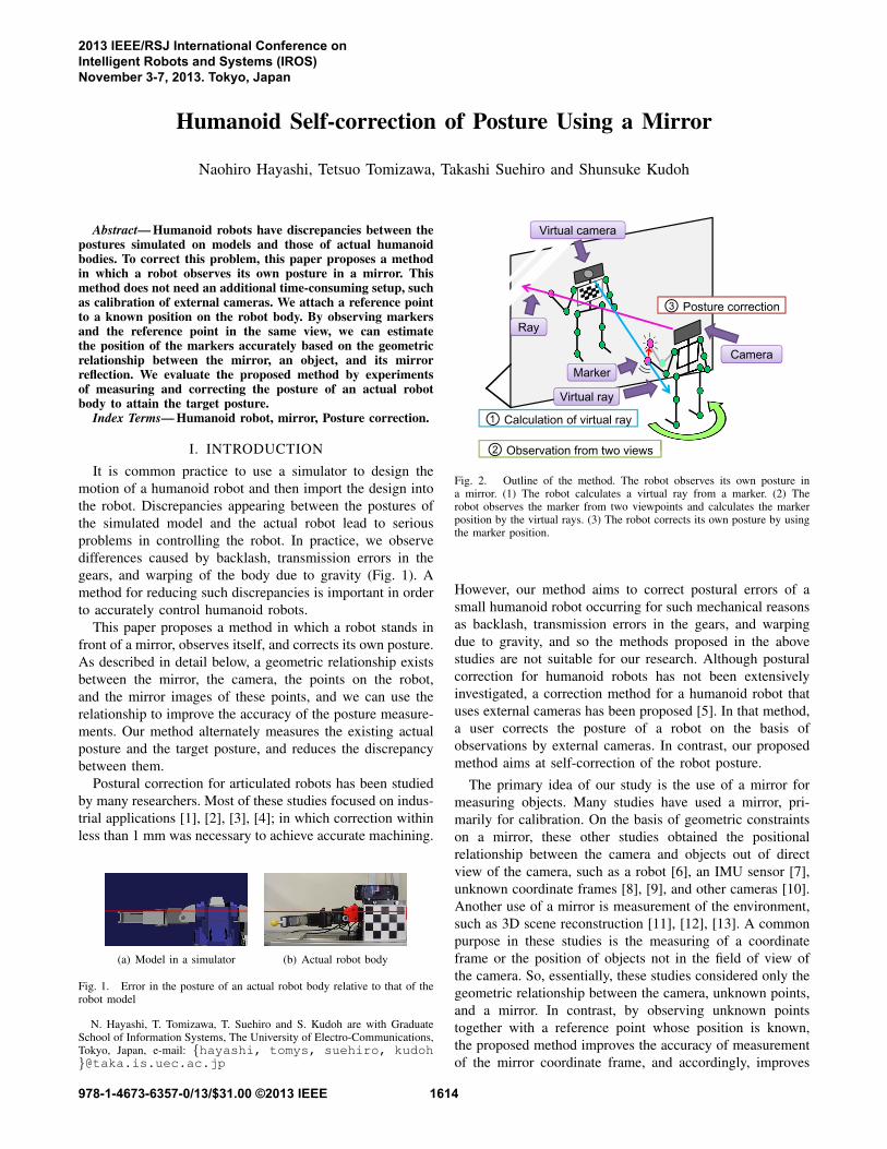
Fig. 2. Outline of the method. The robot observes its own posture ina mirror. (1) The robot calculates a virtual ray from a marker. (2) Therobot observes the marker from two viewpoints and calculates the markerposition by the virtual rays. (3) The robot corrects its own posture by usingthe marker position.
However, our method aims to correct postural errors of a
small humanoid robot occurring for such mechanical reasons
as backlash, transmission errors in the gears, and warping
due to gravity, and so the methods proposed in the above
studies are not suitable for our research. Although postural
correction for humanoid robots has not been extensively
investigated, a correction method for a humanoid robot that
uses external cameras has been proposed [5]. In that method,
a user corrects the posture of a robot on the basis of
observations by external cameras. In contrast, our proposed
method aims at self-correction of the robot posture.
The primary idea of our study is the use of a mirror for
measuring objects. Many studies have used a mirror, pri-
marily for calibration. On the basis of geometric constraints
on a mirror, these other studies obtained the positional
relationship between the camera and objects out of direct
view of the camera, such as a robot [6], an IMU sensor [7],
unknown coordinate frames [8], [9], and other cameras [10].
Another use of a mirror is measurement of the environment,
such as 3D scene reconstruction [11], [12], [13]. A common
purpose in these studies is the measuring of a coordinate
frame or the position of objects not in the field of view of
the camera. So, essentially, these studies considered only the
geometric relationship between the camera, unknown points,
and a mirror. In contrast, by observing unknown points
together with a reference point whose position is known,
the proposed method improves the accuracy of measurement
of the mirror coordinate frame, and accordingly, improves
2013 IEEE/RSJ International Conference onIntelligent Robots and Systems (IROS)November 3-7, 2013. Tokyo, Japan
978-1-4673-6357-0/13/$31.00 ©2013 IEEE 1614
��
���
��
[
[
[¬
[¬
\¬]¬
]¬\¬
\
\
]
]
0LUURU�0LUURU�0LUURU�0LUURU��
���
���
��
���
���
�
5HDO�VSDFH5HDO�VSDFH5HDO�VSDFH5HDO�VSDFH0LUURU�VSDFH0LUURU�VSDFH0LUURU�VSDFH0LUURU�VSDFH
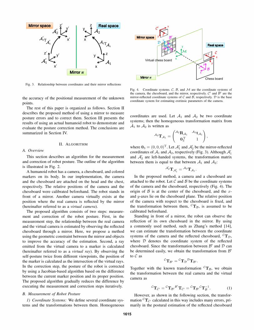
Fig. 3. Relationship between coordinates and their mirror reflections
the accuracy of the positional measurement of the unknown
points.
The rest of this paper is organized as follows. Section II
describes the proposed method of using a mirror to measure
posture errors and to correct them. Section III presents the
results of using an actual humanoid robot to demonstrate and
evaluate the posture correction method. The conclusions are
summarized in Section IV.
II. ALGORITHM
A. Overview
This section describes an algorithm for the measurement
and correction of robot posture. The outline of the algorithm
is illustrated in Fig. 2.
A humanoid robot has a camera, a chessboard, and colored
markers on its body. In our implementation, the camera
and the chessboard are attached on the head and the chest,
respectively. The relative positions of the camera and the
chessboard were calibrated beforehand. The robot stands in
front of a mirror. Another camera virtually exists at the
position where the real camera is reflected by the mirror
(hereinafter referred to as a virtual camera).
The proposed algorithm consists of two steps: measure-
ment and correction of the robot posture. First, in the
measurement step, the relationship between the real camera
and the virtual camera is estimated by observing the reflected
chessboard through a mirror. Here, we propose a method
using the geometric constraint between the mirror and objects
to improve the accuracy of the estimation. Second, a ray
emitted from the virtual camera to a marker is calculated
(hereinafter referred to as a virtual ray). By observing the
self-posture twice from different viewpoints, the position of
the marker is calculated as the intersection of the virtual rays.
In the correction step, the posture of the robot is corrected
by using a Jacobian-based algorithm based on the difference
between the current marker position and its proper position.
The proposed algorithm gradually reduces the difference by
executing the measurement and correction steps iteratively.
B. Measurement of Robot Posture
1) Coordinate Systems: We define several coordinate sys-
tems and the transformations between them. Homogeneous
0LUURU�VSDFH0LUURU�VSDFH0LUURU�VSDFH0LUURU�VSDFH
5HDO�VSDFH5HDO�VSDFH5HDO�VSDFH5HDO�VSDFH
0LUURU�0LUURU�0LUURU�0LUURU��
��
�
��
�
�
�
&KHVV�ERDUG
9LUWXDO�FKHVV�ERDUG
[
\]
[
]
\[
]
y
[
]
[
]
\
[
]\
\
Fig. 4. Coordinate systems. C, B, and M are the coordinate systems ofthe camera, the chessboard, and the mirror, respectively. C′ and B′ are themirror-reflected coordinate systems of C and B, respectively. D is the basecoordinate system for estimating extrinsic parameters of the camera.
coordinates are used. Let A1 and A2 be two coordinate
systems; then the homogeneous transformation matrix from
A1 to A2 is written as
A2TA1=
(
A2RA1
A2tA1
0T3 1
)
,
where 03 = (0, 0, 0)T. Let A′1 and A′
2 be the mirror-reflected
coordinates ofA1 andA2, respectively (Fig. 3). AlthoughA′1
and A′2 are left-handed systems, the transformation matrix
between them is equal to that between A1 and A2:
A′
2TA′
1= A2TA1
.
In the proposed method, a camera and a chessboard are
attached to the robot. Let C and B be the coordinate systems
of the camera and the chessboard, respectively (Fig. 4). The
origin of B is at the center of the chessboard, and the x-
and y-axes lie on the chessboard plane. The relative position
of the camera with respect to the chessboard is fixed, and
the transformation between them, CTB, is assumed to be
calibrated beforehand.
Standing in front of a mirror, the robot can observe the
reflection of its own chessboard in the mirror. By using
a commonly used method, such as Zhang’s method [14],
we can estimate the transformation between the coordinate
systems of the camera and the reflected chessboard, CTD,
where D denotes the coordinate system of the reflected
chessboard. Since the transformation between B′ and D can
be determined easily, we obtain the transformation from B′
to C asCTB′ = CTD
DTB′ .
Together with the known transformation CTB, we obtain
the transformation between the real camera and the virtual
camera as
CTC′ = CTB′
B′
TC′ = CTB′
CT−1
B. (1)
However, as shown in the following section, the transfor-
mation CTC′ calculated in this way includes many errors, pri-
marily in the postural estimation of the reflected chessboard
1615
(i.e., the rotational component of CTD), especially when
the chessboard is directly in front of the camera. This error
greatly affects the estimation of the robot posture. Therefore,
to calculate CTC′ , we use another method that does not use
the rotational component CRD, but instead use the geometric
constraints of the mirror.
Let b and b′ be the origins of B and B′, respectively. They
are obtained as
Cb = CTB
(
03
1
)
and Cb′ = CTB′
(
03
1
)
,
where Cb denotes point b represented with respect to C.
Since b′ is the reflection of b , the following relationship
holds between b, b′, and the mirror: the mirror plane passes
through the midpoint of b and b′, and the normal vector
of the mirror plane is parallel to b′ − b. By using this
relationship, the mirror plane can be determined. The mirror
coordinate system M is defined so that the origin is at the
midpoint of b and b′, and the z-axis is parallel to b
′ − b.
Since an arbitrariness remains about the x- and y-axes, we
designate the x-axis to be parallel to the projection of the
x-axis of C to the mirror plane. With this formulation, the
translational and rotational components of CTM are written
as
CtM =Cb̃′ + Cb̃
2
CRM =
(
mx my mz
)
mz =Cb̃′ − Cb̃
‖Cb̃′ − Cb̃‖
mx =ex − (ex,mz)mz
‖ex − (ex,mz)mz‖
my = mz ×mx,
where ex = (1, 0, 0)T, and b̃ and b̃′ are the points in
Euclidean space corresponding to points b and b′ in the
homogeneous space, respectively.
With respect toM, because the coordinate systems C and
C′ are inverse about the z-axis, the following relationship
holds:
MTC′ = PMTC = P CT−1
M,
where
P =
1 0 0 00 1 0 00 0 −1 00 0 0 1
.
With the above equations, we obtain the transformation
between the real camera and the virtual camera as
CTC′ = CTMMTC′ . (2)
9LUWXDO�UD\���������
5D\��������
��
�
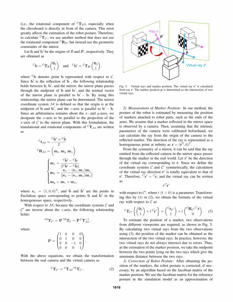
Fig. 5. Virtual rays and marker position. The virtual ray r′ is calculated
from ray r. The marker position p is determined as the intersection of twovirtual rays.
2) Measurement of Marker Position: In our method, the
posture of the robot is estimated by measuring the position
of markers attached to robot parts, such as the ends of the
arms. We assume that a marker reflected in the mirror space
is observed by a camera. Then, assuming that the intrinsic
parameters of the camera were calibrated beforehand, we
can calculate the ray from the origin of the camera to the
reflected marker. The direction of the ray is represented as a
homogeneous point at infinity as r = (r̃T, 0)T.
From the symmetry of a mirror, it can be said that the ray
emitted from the reflected camera in the mirror space passes
through the marker in the real world. Let r′ be the direction
of the virtual ray corresponding to r. Since we define the
coordinate systems C and C′ symmetrically, the calculation
of the virtual ray direction r′ is totally equivalent to that of
r′. Therefore, C′
r′ = Cr, and the virtual ray can be written
as
t C′
r′
with respect to C′, where t (t > 0) is a parameter. Transform-
ing this by (1) or (2), we obtain the formula of the virtual
ray with respect to C as
CTC′
{(
03
1
)
+ t C′
r′}
=
(
CtC′
1
)
+ t
(
CRC′C′
r̃
0
)
. (3)
To estimate the position of a marker, two observations
from different viewpoints are required, as shown in Fig. 5.
By calculating two virtual rays from the two observations
using (3), the position of the marker can be obtained as the
intersection of the two virtual rays. In practice, however, the
two virtual rays do not always intersect due to errors. Thus,
as the estimation of the marker position, we take the midpoint
between the two points lying on the two rays which give the
minimum distance between the two rays.
3) Correction of Robot Posture: After obtaining the po-
sition of the markers, the robot posture is corrected, if nec-
essary, by an algorithm based on the Jacobian matrix of the
marker position. We use the Jacobian matrix for the reference
posture in the simulation model as an approximation of
1616
that for the actual robot posture. In practice, because the
actual posture is affected by several complicated factors, such
as warping and backlashes, the these two matrices are not
equivalent. Hence, we iterate the correction steps until the
actual posture converges to the target posture. In each step
of the correction, the angles of joints θ are updated by adding
∆θ = λJ+∆p,
where ∆p = pref − pcul (pref and pcul are the marker
positions of the designed target posture and the actual
robot posture, respectively), J+ is the pseudo-inverse of the
Jacobian matrix, and λ is a gain. Algorithm 1 summarizes
the above description.
The reason for using gain λ is as follows. If a joint angle
overshoots an appropriate angle due to a correction step,
it can harm the convergence of the iteration because the
actuators often have different rotational directions. Therefore,
we introduce a small gain λ so that the marker position
approaches the target position gradually.
Algorithm 1 Posture Correction (θref , pref , λ)
θ ← θref
J+ ← J(θref)+
loop
Observing pcul
∆p← pref − pcul
if ‖∆p‖ < ε then
return
end if
θ ← θ + λJ+∆p
end loop
III. EXPERIMENT
A. Experimental Setup
The humanoid robot used for the experiments consists of
the following equipment:
Robot: G-ROBOT (HPI), Height: 255 mm
Chessboard: 14 mm × 14 mm for each square
Finger markers: Sphere diameter: 11.6 mm
Head camera: Webcam C910 (Logitech)
Resolution of an image: Resolution: 800 × 600 pixels
Mirror: Glass mirror, thickness: 3 mm
The relationship between the camera and the chessboard is
calibrated by using another camera and chessboard. The new
chessboard is set in the field of view of the robot’s camera.
The new camera is set in a place where it can observe both
chessboards. The relationship between the robot’s camera
and the robot’s chessboard is derived from the relationships
of these cameras and these chessboards.
The position of the markers in the images are detected by
color extraction and labeling. It is assumed that the region
of a marker is always larger than any other regions that have
the same color as the marker.
� �
�
�� ���� �� �������� �� ���
�� ���� �� ��
������ �� ���
�� ���� �� �� ������ ��� ��
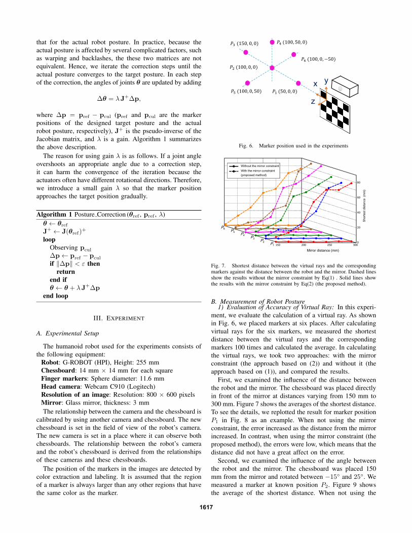
Fig. 6. Marker position used in the experiments
��
��
��
��
�
��� ��� ��� ���
3�3�
3�3�
3�3�
0LUURU�GLVWDQFH��PP�
6KRUWHVW�GLVWDQFH���PP�
:LWKRXW�WKH�PLUURU�FRQVWUDLQW
:LWK�WKH�PLUURU�FRQVWUDLQW
�SURSRVHG�PHWKRG�
Fig. 7. Shortest distance between the virtual rays and the correspondingmarkers against the distance between the robot and the mirror. Dashed linesshow the results without the mirror constraint by Eq(1) . Solid lines showthe results with the mirror constraint by Eq(2) (the proposed method).
B. Measurement of Robot Posture1) Evaluation of Accuracy of Virtual Ray: In this experi-
ment, we evaluate the calculation of a virtual ray. As shown
in Fig. 6, we placed markers at six places. After calculating
virtual rays for the six markers, we measured the shortest
distance between the virtual rays and the corresponding
markers 100 times and calculated the average. In calculating
the virtual rays, we took two approaches: with the mirror
constraint (the approach based on (2)) and without it (the
approach based on (1)), and compared the results.
First, we examined the influence of the distance between
the robot and the mirror. The chessboard was placed directly
in front of the mirror at distances varying from 150 mm to
300 mm. Figure 7 shows the averages of the shortest distance.
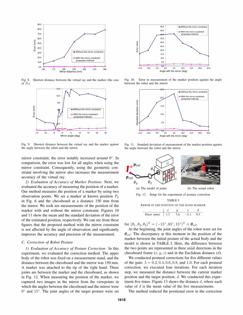
To see the details, we replotted the result for marker position
P1 in Fig. 8 as an example. When not using the mirror
constraint, the error increased as the distance from the mirror
increased. In contrast, when using the mirror constraint (the
proposed method), the errors were low, which means that the
distance did not have a great affect on the error.
Second, we examined the influence of the angle between
the robot and the mirror. The chessboard was placed 150
mm from the mirror and rotated between −15◦ and 25◦. We
measured a marker at known position P2. Figure 9 shows
the average of the shortest distance. When not using the
1617
ÜÚÜ
ÝÜÚÜ
ÞÜÚÜ
ßÜÚÜ
àÜÚÜ
áÜÚÜ
âÜÚÜ
ãÜÚÜ
äÜÚÜ
åÜÚÜ
ÝáÜ Ýãá ÞÜÜ ÞÞá ÞáÜ Þãá ßÜÜ
Err
or
(mm
)
Mirror distance (mm)
Without the mirror constraint
With the mirror constraint(proposed method)
Fig. 8. Shortest distance between the virtual ray and the marker (the caseof P1)
ÜÚÜ
ÞÚÜ
àÚÜ
âÚÜ
äÚÜ
ÝÜÚÜ
ÝÞÚÜ
ÙÝá ÙÝÜ Ùá Ü á ÝÜ Ýá ÞÜ Þá
Err
or
(mm
)
Mirror angle (deg)
Without the mirror constraint
With the mirror constraint(proposed method)
Fig. 9. Shortest distance between the virtual ray and the marker againstthe angle between the robot and the mirror
mirror constraint, the error notably increased around 0◦. In
comparison, the error was low for all angles when using the
mirror constraint. Consequently, using the geometric con-
straint involving the mirror also increases the measurement
accuracy of the virtual ray.
2) Evaluation of Accuracy of Marker Position: Next, we
evaluated the accuracy of measuring the position of a marker.
Our method measures the position of a marker by using two
observation points. We set a marker at known position P2
in Fig. 6 and the chessboard at a distance 150 mm from
the mirror. We took ten measurements of the position of the
marker with and without the mirror constraint. Figures 10
and 11 show the mean and the standard deviation of the error
of the estimated position, respectively. We can see from these
figures that the proposed method with the mirror constraint
is not affected by the angle of observation and significantly
improves the accuracy and precision of the measurement.
C. Correction of Robot Posture
1) Evaluation of Accuracy of Posture Correction: In this
experiment, we evaluated the correction method. The upper
body of the robot was fixed on a measurement stand, and the
distance between the chessboard and the mirror was 150 mm.
A marker was attached to the tip of the right hand. Three
joints are between the marker and the chessboard, as shown
in Fig. 12. When measuring the position of the marker, we
captured two images in the mirror from the viewpoints in
which the angles between the chessboard and the mirror were
0◦ and 15◦. The joint angles of the target posture were set
ÜÚÜ
áÚÜ
ÝÜÚÜ
ÝáÚÜ
ÞÜÚÜ
ÞáÚÜ
ßÜÚÜ
ßáÚÜ
àÜÚÜ
àáÚÜ
áÜÚÜ
ÙÝáÚÜ ÙÝÜÚÜ ÙáÚÜ ÜÚÜ áÚÜ ÝÜÚÜ ÝáÚÜ ÞÜÚÜ ÞáÚÜ
Err
or
(mm
)
Angle with the mirror (deg)
Without the mirror constraint
With the mirror constraint(proposed method)
Fig. 10. Error in measurement of the marker position against the anglebetween the robot and the mirror
ÜÚÜ
áÚÜ
ÝÜÚÜ
ÝáÚÜ
ÞÜÚÜ
ÞáÚÜ
ÙÝáÚÜ ÙÝÜÚÜ ÙáÚÜ ÜÚÜ áÚÜ ÝÜÚÜ ÝáÚÜ ÞÜÚÜ ÞáÚÜ
Sta
nd
ard
de
via
tion
(m
m)
Angle with the mirror (deg)
Without the mirror constraint
With the mirror constraint(proposed method)
Fig. 11. Standard deviation of measurement of the marker position againstthe angle between the robot and the mirror
��
��������
��
[
]
\
�
(a) The model of joints (b) The actual robot
Fig. 12. Setup for the experiment of posture correction
TABLE I
ERROR IN THE POSITION OF THE HAND MARKER
x y z d
Error (mm) 1.7 7.6 −5.1 9.3
for (θ1, θ2, θ3)T = (−15◦, 85◦, 15◦)T ≡ θref .
At the beginning, the joint angles of the robot were set for
θref . The discrepancy at this moment in the position of the
marker between the initial posture of the actual body and the
model is shown in TABLE I. Here, the difference between
the two points are represented in three axial directions in the
chessboard frame (x, y, z) and in the Euclidean distance (d).
We conducted postural corrections for five different values
of the gain: λ = 0.2, 0.4, 0.6, 0.8, and 1.0. For each postural
correction, we executed four iterations. For each iteration
step, we measured the distance between the current marker
position and the target position, d. We conducted this exper-
iment five times. Figure 13 shows the distance d, where each
value of d is the mean value of the five measurements.
The method reduced the positional error in the correction
1618
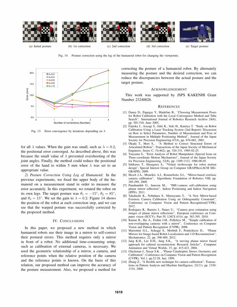
(a) Initial posture (b) 1st correction (c) 2nd correction (d) 3rd correction (e) Target posture
Fig. 14. Posture correction using the leg of the humanoid robot for changing the viewpoints.
ÜÚÜ
áÚÜ
ÝÜÚÜ
ÝáÚÜ
ÞÜÚÜ
Ü Ý Þ ß à
Err
or
(mm
)
Number of corrections (Number)
�=0.2
�=0.4
�=0.6
�=0.8
�=1.0
Fig. 13. Error convergence by iterations depending on λ
for all λ values. When the gain was small, such as λ = 0.2,
the positional error converged. As described above, this was
because the small value of λ prevented overshooting of the
joint angles. Finally, the method could reduce the positional
error of the hand to within 5 mm when λ was set to an
appropriate value.
2) Posture Correction Using Leg of Humanoid: In the
previous experiments, we fixed the upper body of the hu-
manoid on a measurement stand in order to measure the
error accurately. In this experiment, we rotated the robot on
its own legs. The target posture was θ1 = −15◦, θ2 = 85◦,
and θ3 = 15◦. We set the gain to λ = 0.2. Figure 14 shows
the position of the robot at each correction step, and we can
see that the warped posture was successfully corrected by
the proposed method.
IV. CONCLUSIONS
In this paper, we proposed a new method in which
humanoid robots use their image in a mirror to self-correct
their postural errors. This method requires only a mirror
in front of a robot. No additional time-consuming setup,
such as calibration of external cameras, is necessary. We
used the geometric relationship of a mirror, a camera, and
reference points when the relative position of the camera
and the reference points is known. On the basis of this
relation, our proposed method can improve the accuracy of
the posture measurement. Also, we proposed a method for
correcting the posture of a humanoid robot. By alternately
measuring the posture and the desired correction, we can
reduce the discrepancies between the actual posture and the
target posture.
ACKNOWLEDGEMENT
This work was supported by JSPS KAKENHI Grant
Number 23240026.
REFERENCES
[1] Daney D., Papegay Y., Madeline B., “Choosing Measurement Posesfor Robot Calibration with the Local Convergence Method and TabuSearch”, International Journal of Robotics Research Archive 24(6),pp. 501-518, June 2005.
[2] Fujioka J., Aoyagi S., Ishii K., Seki H., Kamiya T. “Study on RobotCalibration Using a Laser Tracking System (2nd Report): Discussionon How to Select Parameters, Number of Measurement and Pose ofMeasurement in Multiple Positioning Method”, Journal of the JapanSociety for Precision Engineering 67(4), pp. 676-682, 2001.
[3] Okada T., Mori S., “A Method to Correct Structural Errors ofArticulated Robots”, Transactions of the Japan Society of MechanicalEngineers, Series C, 51(462), pp. 324-331, 1985-02-25.
[4] Touyama S., “Error Analysis of Robot Manipulator (Special Issue onThree-coordinate Motion Mechanism)”, Journal of the Japan Societyfor Precision Engineering, 52(8), pp. 1309-1312, 1986-08-05.
[5] Ishikawa T., Hasegawa S., “Virtual stroboscope for robot motiondesign”, Special Interest Group on Computer GRAPHics(ACM SIG-GRAPH), 2009.
[6] Hesch J.A., Mourikis A.I., Roumeliotis S.I., “Mirror-based extrinsiccamera calibration”, Algorithmic Foundation of Robotics VIII, pp.285-299, 2009.
[7] Panahandeh G., Jansson M., “IMU-camera self-calibration usingplanar mirror reflection”, Indoor Positioning and Indoor Navigation(IPIN), 2011.
[8] Takahashi K., Nobuhara S., Matsuyama T., “A New Mirror-basedExtrinsic Camera Calibration Using an Orthogonality Constraint”,Conference on Computer Vision and Pattern Recognition(CVPR),2012.
[9] Rodrigues R., Barreto J., Nunes U., “Camera pose estimation usingimages of planar mirror reflections”, European conference on Com-puter vision (ECCV), Part IV, LNCS 6314, pp. 382-395, 2010.
[10] Kumar R., Ilie A., Frahm J.M., Pollefeys M., “Simple calibration ofnon-overlapping cameras with a mirror”, Conference on ComputerVision and Pattern Recognition (CVPR), 2008.
[11] Mariottini G.L., Scheggi S., Morbidi F., Prattichizzo D., “PlanarMirrors for Image-based Robot Localization and 3-D Reconstruction”,Mechatronics, 22, pp. 398-409, 2012.
[12] Jang K.H., Lee D.H., Jung S.K., “A moving planar mirror basedapproach for cultural reconstruction: Research Articles”, ComputerAnimation and Virtual Worlds, 15, pp. 415-423, 2004.
[13] Gluckman J., Nayar S.K. , “Planar Catadioptric Stereo: Geometry andCalibration”, Conference on Computer Vision and Pattern Recognition(CVPR), Vol.1, pp.22-28, Jun, 1999.
[14] Zhang Z., “A flexible new technique for camera calibration”, Transac-tions on Pattern Analysis and Machine Intelligence, 22(11), pp. 1330-1334, 2000.
1619