Embed Size (px)
Citation preview

product manual12.10
HM-1327
Humboldt Marshall/TSR Loader
TABLE OF CONTENTS
Introduction ...........................................................................................1ApplicationsProduct UseProduct Description
General Warnings ...................................................................... 2Safety WarningsElectrical Warnings
Manufacturer’s Rights and Responsibilities ............................... 2Software Copyright Important Notice ............................................................................. 3Updated products ............................................................................ 3 Fitness for application ...................................................................... 3
Quick Start Guide ...................................................................... 4Startup Scenarios
Installation and Set-up ............................................................... 5Unpacking ........................................................................................ 5Electrical Connections ...................................................................... 5Instrument Inputs (transducer connections) ................................. 5, 6Mounting Transducers ...................................................................... 6 Computer Connection ..................................................................... 7 Single Device Connection ................................................................ 7 Analog Device Connection .............................................................. 7
Operation ...................................................................................8Power Switch .................................................................................... 8Key Function ..................................................................................... 8Set Up Key ........................................................................................ 9Speed Key ........................................................................................ 9Up Key .............................................................................................. 9Stop Key ........................................................................................... 9Down Key ......................................................................................... 9Function Keys ................................................................................... 9
Set-Up Functions ......................................................................10Set Date ......................................................................................... 10Set Time ......................................................................................... 11Set Units ......................................................................................... 12Set Standards ................................................................................. 13

©2010 Humboldt Mfg. Co.
Input Configuration ........................................................................ 14Configuring Input ........................................................................... 15Sensor Min ..................................................................................... 16Sensor Max ..................................................................................... 16Calibration ............................................................................... 17
Device ID ................................................................................. 19
Standard Tests ......................................................................... 20Marshall ......................................................................................... 21Soil Cement/TSR ............................................................................ 22 Software .................................................................................. 23 HM Download Software ................................................................. 23 Specifications ........................................................................... 24
Test Accessories ...................................................................... 24
Support .................................................................................... 25
Hidden Functions ..................................................................... 25
Notes ....................................................................................... 26 Notes ....................................................................................... 27

IntroductionApplicationsThe HM-1327 Marshall Loader is designed specifically for running Marshall and TSR tests. Its modular design minimizes initial costs and allows easy upgrades. And with array of connectivity options, data presentation has never been easier.
Product UseThis product is intended for use only in accordance with the directions and specifications contained in this User Guide. Your HM-1327 has been configured according to your specifications.
The HM-1327 Marshall Loader has been designed for testing that complies with ASTM D6927 and D4123-82 and AASHTO T245, T283, BS 598-107, and applicable International standards. Product DescriptionHM 1327 Marshall Loader has been designed to provide all the basic functions required to carry out Hot Mixed Asphalt (Marshall, TSR) testing in a single instrument. Your Compression Testing Frame/Master Loader arrives factory calibrated.
The HM 1327 Marshall Loader includes the following key features:
• Singlespeedmotorof2in/min(orequivalent50mm/min).
• Supportfor2analoguetransducerinputsfrom0to100mV(oneloadand one displacement transducer). Configuration and calibration capability is provided, and all-important data is stored in non-volatile memory for safe preservation.
• CompleteDataloggercapacityfortheMarshallandTSRtests.Allarefully configurable for automated Start, Stop and Logging conditions and can hold up to 1000 readings per test.
• AlargeLCDscreenand9keymembranepanelforeasypresentationof results, parameter configuration, and machine control. To protect against operator misuse, key parameters can only be changed under pass code control.
1

• PlugandplaySerialport(RS232)communicationswithHumboldtMaterial Testing Software (HMTS) for controlling and HM Download Software for downloading machine run test data.
In addition, the loader offers a large, backlit LCD display, a touch-sensitive keypad, a battery-backed real time clock, and auto-conversion of calibration and speed parameters between English and SI units.
General WarningsSafety Warnings Operators should take care to operate this machine under the maximum load restrictions. The machine is programmed at the factory to provide safety shutdown if the upper or lower maximum travel is exceeded as well as if the upper instrument calibration is exceeded.
Electrical Warnings Typically, there is no reason for the operator to open the machine. However, if the customer’s engineers attempt to change settings to the circuit board connected to the back panel, the machine must always be unplugged before this operation. Unplugging the internal connection to the back panel circuit board while the machine is under power will result in permanent damage to the circuit board.
Manufacturer’s Rights and Responsibilities
Software Copyright
COPYRIGHTNOTICE
©2010 HUMBOLDT MFG. CO.All Rights Reserved.
This manual or parts thereof, may not bereproduced in any form without the expressed written
permission of HUMBOLDT MFG. CO.
UNPUBLISHEDLICENSEDPROPRIETARYWORK©2010 HUMBOLDT MFG. CO.
2

The programmable, read-only memory, integrated circuit package contained in this equipment and covered with a copyright notice label contains proprietary and confidential software, which is the sole property of HUMBOLDT MFG. CO. It is licensed for use by the original purchaser of this equipment for a period of 99 years. Transfer of the license can be obtained by a request, in writing, from HUMBOLDT MFG. CO.
WiththeexceptionofHUMBOLDTAuthorizedServiceFacilitiesyoumaynot copy, alter, de-compile, or reverse assemble the software in any fashion except as instructed in this manual. US copyright laws, trademark laws, and trade secrets protect the materials.
Any person(s) and /or organizations that attempt or accomplish the above violation or knowingly aid or abet the violation by supplying equipment or technology will be subject to civil damages and criminal prosecution.
IMPORTANT NOTICEThe information contained herein is supplied without representation or warranty of any kind. Humboldt MFG. CO. therefore assumes no responsibility and shall have no liability, consequential or otherwise, of any kind arising from the use of the described equipment contained in this manual.
Updated productsThe manufacturer reserves the right to change or modify product design or construction without prior notice and without incurring any obligation to make such changes and modifications on products previously or subsequently sold.
Fitness for applicationThe manufacturer makes no recommendations or claims regarding fitness
for applications other than the specific tests as defined in this User Guide.
3

1
Quick Start GuideStartup Scenarios
If your HM-1327 was purchased with instrumentation for one specific test: the instrumentation has been installed and calibrated. There is no need to configure or calibrate the machine. It is ready for use.
DO NOT RECALIBRATE!
Refer to the Installation and Setup Section and then proceed to the section for the specific test desired.
If your HM-1327 was purchased with instrumentation for multiple tests: one of those tests is ready for use and the additional tests may or may not require the mounting of a different transducer than the one that is currently mounted. However all instrumentation shipped with your unit is calibrated and assigned specific input channels for use. These input channels are marked on the corresponding instrumentation. Unless it is required by your QC/QA program, there is no need to configure or calibrate the
machine. It is ready for use.DO NOT RECALIBRATE!
Refer to the Installation and Setup Section and then proceed to the section for the specific test desired.
If your HM-1327 was purchased without instrumentation for specific tests: you will need to acquire, check compatibility, mount and calibrate your instrumentation for use with the HM-1327.
Refer to the Installation and Setup Section to make sure if your instrumentation is compatible with the HM-1327. You will need to calibrate your instrumentation, please refer to configuration and calibration instructions. You can then proceed to the Section for the specific test desired.
2
3
4

Installation and Set-upUnpackingInitial inspection should include checking for physical damage during shipping and obvious external damage to the product.
Packagecontentsaredefinedbyyourpackinglist.EachMarshallLoaderis configured according to customer specifications. In your inspection, make certain that the contents of your shipment match the documentation provided by your packing list.
Placeunitonaflatsmoothsurfaceanduselevelingfeet(supplied)andabubble level to ensure that the unit is level side-to-side and back-to-front.
Electrical ConnectionsThe HM-1327 is equipped with an internal, digital, switching power supply, which allows it to be used with most power configurations throughout the world. The unit is supplied with an IEC electrical cord with a standard 110Vplug.
The HM-1327 arrives ready for operation. Attach the supplied IEC electrical cord to the machine and plug into a standard wall receptacle for use in the United States.
For locations other than the U.S., replace the supplied electrical cord with an IEC cord with the correct plug for your application. The supplied cord can also be used by cutting the standard plug from the cord and attaching the correct plug.
Instrument Inputs (load cell/transducer connections)The HM-1327 has 2 instrumentation inputs located on the back panel to ac-commodate load cell/transducer connections. This feature allows you to set up and calibrate up to 2 different instruments, which the unit can quickly switch between for those needing to do multiple types of tests.
If you purchased load cells/transducers with your unit, they will either be mounted and calibrated, or in the case of multiple load cells/transducers, will be calibrated but not mounted. Additional load cells/transducers will be marked to indicate what input channel was used in the calibration; and, these load cells/transducers should be connected to the indicated inputs.
Third-party load cells/transducers, which are compatible, can also be used with the HM-1327. Compatible units will have an excitation voltage of 0-10voltsandanoutputof0-100millivolts.Priortouseallthird-party instrumentationmustbeconfiguredandcalibratedforuse.Pleaserefertothe Configuration and Calibration sections of this manual.
5

If you are using third-party cables for load cells/transducers connections, make sure they are wired to be compatible with the HM-1327. Consult Figure#1foracompatiblereferencewiringdiagram.Plugstoconnect third-party instrumentation to the Humboldt HM-1327 are available, order part HM-000474.
Mounting Load Cells and TransducersIf you purchased your HM-1327 with instrumentation, one of the load cell/transducer setups should already be mounted. If you are using the machine for multiple tests or want to use instrumentation not included, including third-party instrumentation, the following photos can be used as a guide for load cells/transducers setup.
Figure 1. Compatibility wiring diagram for 3rd party cables
Pin3= +dc OutputPin4= –dc Output
6
Figure 2. Marshall Setup Figure 3. TSR/Soil Cement Setup

Computer ConnectionSingle Device ConnectionTheHM-1327canbeconnectedtoaPCcomputertotakeadvantageofHumboldt’s HMTS software capabilities, conduct real time data logging and enhanced report generation, or with the HM Download Software to download tests performed directly on the device. This is accomplished via the RS-232 port on the back panel of the machine (refer to Figures 7 & 8.). Use a RS-232 cable (supplied) and attach it between the computer’s RS-232 port and the HM-1327.
TheminimumcompatiblecomputerconfigurationisaPCwithPentiumIII800MHzprocessor,512MBofRAManda40GBharddrive.Windows2000orXPwithSP2orlater.
Analog Device ConnectionThe HM-1327 can be set up to output directly to a chart recorder to provide a hard copy printout of test results. To accomplish this, connect your chart recorder via cable attached to the HM-1327’s Analogue port on the back panel (see Figure 7).
7
Figure 7. Rear panel of HM-1327 showing Chart Recorder Port, RS-232 Port and the two instrumentation channel inputs.
69
5 1
sweepresetnot
connected
CH3 CH4 CH1 CH2
D-SUB, 9-PIN MALE
ANALOG PORT ACCESS
Cable configuration for analogue port access.
Pins 1, 2, 3 & 4 (Reserved for Humboldt Chart Recorder)

OperationPower SwitchThePowerSwitchislocatedinthebackpanelontherearofthemachineabove the electrical cord inlet. Also, located between the electrical cord inletandthePowerSwitchistheFuseCompartment.TheHM-1327usesa10ampfuse.Tobeginoperation,pressthePowerSwitch.
Figure 10. HM-1327 Power Switch, Electrical Cord Inlet and Fuse Compartment.
Figure 11. HM-1327 Front Control Panel
Key Functions
Fuse Compartment.
8

Set Up KeyPushingtheSetUpKeybringsupthemainsetupscreenfrom which you can run a test, review your last test, access the engineering set up menus and set the date, time, units, standards criteria. This key also is used to return to a previous screen.
Up KeyPushingtheUpKeyallowsyoutomovetheplatenuptofacilitatetesting.Whenthekeyispushedthegreenlight next to it is lit.
Stop KeyPushingtheStopKeystopsplatenmovement.Whenthekeyispushed the red light next to it is lit.
Down KeyPushingtheDownKeyallowsyoutomovetheplatendown. Whenthekeyispushedthegreenlightnexttoitislit.
Function KeysThe four function keys are used to navigate through the HM-1327’s menu-driven display. The function keys correspond with the command lines on the HM-1327’s menu display. F1 corresponds with the first command line; F2, the second, etc. Command lines that are active in any display will be proceeded by an (*). If no (*) is present, the corresponding function key is not active.
9
Humboldt HM-1327
STAB = 1.2 lbsFLOW = 0.003 in
Except when viewing inputs values as above left, the function keys will perform a tare function to the displayed value and "T" will be displayed next to the input name to indicate that the value of the input has a tare (above right).
Humboldt HM-1327
STAB T = 0.0 lbsFLOW T = 0.000 in

Set-up FunctionsSet DateTo set the Date press until you see this screen:
Press you will see this screen:
Press you will see this screen:
Press you will see this screen:
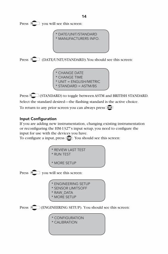
Press (DATE/UNIT/STANDARD).Youshouldseethisscreen:
* REVIEW LAST TEST* RUN TEST
* MORE SETUP
* ENGINEERING SETUP* SENSOR LIMITS OFF* RAW_DATA * MORE SETUP
* RECALL CALIBRATION* CHANGE DEVICE ID
* MORE SETUP
10
10
* DATE/UNIT/STANDARD* MANUFACTURERS INFO.
* CHANGE DATE* CHANGE TIME* UNIT = ENGLISH/METRIC* STANDARD = ASTM/BS
Press (CHANGEDATE).Youshouldseethisscreen:
Press (DATE)toselectthemonth/date/year.Press (INCREASE)
orPress (DECREASE) to change the appropriate number.
To return to any prior screen you can always press
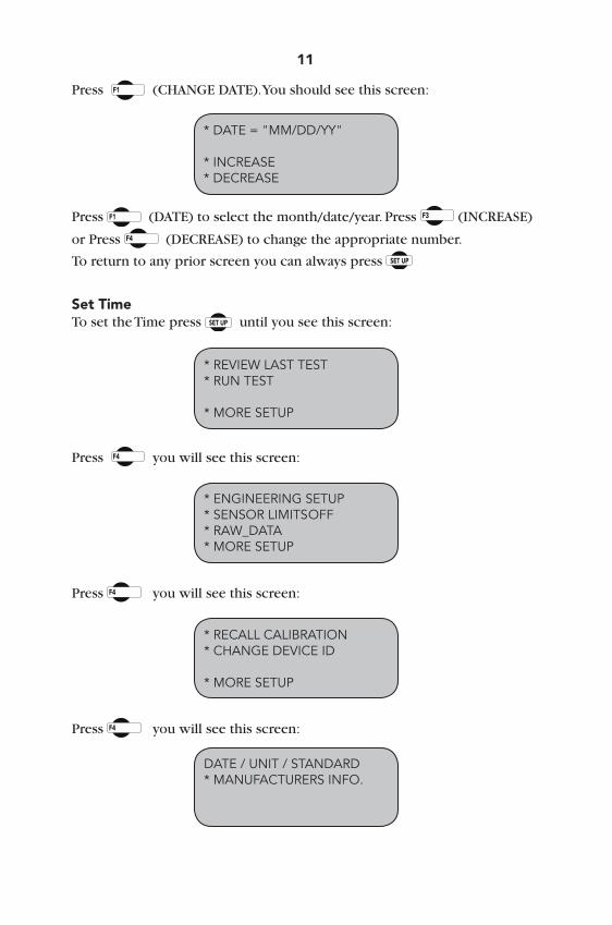
Set TimeTo set the Time press until you see this screen:
Press you will see this screen:
Press you will see this screen:
Press you will see this screen:
* DATE = "MM/DD/YY"
* INCREASE* DECREASE
* REVIEW LAST TEST* RUN TEST
* MORE SETUP
* ENGINEERING SETUP* SENSOR LIMITS OFF* RAW_DATA* MORE SETUP
* RECALL CALIBRATION* CHANGE DEVICE ID
* MORE SETUP
DATE / UNIT / STANDARD* MANUFACTURERS INFO.
11

12
Press (DATE/UNIT/STANDARD).Youshouldseethisscreen:
Press (CHANGETIME).Youshouldseethisscreen:
Press (TIME)toselecttheHOURS/MINUTES/SECONDS.Press
(INCREASE).orPress (DECREASE) to change the appropriate number.
To return to any prior screen you can always press
* TIME = "HH/MM/SS"
* INCREASE* DECREASE
* CHANGE DATE* CHANGE TIME* UNIT = ENGLISH/METRIC* STANDARD = ASTM/BS
Set UnitsTo set the Units the HM-1327 will use to display results, press until you see this screen:
Press you will see this screen:
Press you will see this screen:
* REVIEW LAST TEST* RUN TEST
* MORE SETUP
* ENGINEERING SETUP* SENSOR LIMITS OFF* RAW_DATA* MORE SETUP
* RECALL CALIBRATION* CHANGE DEVICE ID * MORE SETUP

Press you will see this screen:
Press (DATE/UNIT/STANDARD).Youshouldseethisscreen:
Press (units) to toggle between English and Metric Units.
Selectthestandarddesired—theflashingstandardistheactivechoice.
To return to any prior screen you can always press
Set StandardsTo set the Standards the HM-1327 will use, press until you see this screen:
Press you will see this screen:
Press you will see this screen:
13
* DATE/UNIT/STANDARD* MANUFACTURES INFO
* CHANGE DATE* CHANGE TIME* UNIT = ENGLISH/METRIC* STANDARD = ASTM/BS
* REVIEW LAST TEST* RUN TEST
* MORE SETUP
* ENGINEERING SETUP* SENSOR LIMITS OFF* RAW_DATA* MORE SETUP
* RECALL CALIBRATION* CHANGE DEVICE ID
* MORE SETUP
14
Press you will see this screen:
Press (DATE/UNIT/STANDARD).Youshouldseethisscreen:
Press (STANDARD)totogglebetweenASTMandBRITISHSTANDARD.
Selectthestandarddesired—theflashingstandardistheactivechoice.
To return to any prior screen you can always press
* DATE/UNIT/STANDARD* MANUFACTURERS INFO.
* CHANGE DATE* CHANGE TIME* UNIT = ENGLISH/METRIC* STANDARD = ASTM/BS
Input ConfigurationIf you are adding new instrumentation, changing existing instrumentation or reconfiguring the HM-1327’s input setup, you need to configure the input for use with the devices you have.To configure a input, press You should see this screen:
Press you will see this screen:
Press (ENGINEERINGSETUP).Youshouldseethisscreen:
* REVIEW LAST TEST* RUN TEST
* MORE SETUP
* ENGINEERING SETUP* SENSOR LIMITS OFF* RAW_DATA* MORE SETUP
* CONFIGURATION* CALIBRATION

15
Press (CONFIGURATION)Youwillbeaskedforapassword,enter:
You should see this screen:
Press (SELECTINPUT)toscrollthroughandchoosetheinputyou wish to configure. Once you have selected a channel press (CONFIGUREINPUT).Youshouldseethisscreen:
Configuring Input The Configuration screen will allow us to configure the Sensor Max value. The sensor max value contains the formatting of this input as well as the maximum value we will be calibrating to.
CONFIGURATION screen* SELECT INPUT "CHI"* CONFIGURE CHANNEL
INPUT 1 CONFIGURENAME = STABSENSOR MIN = 0*SENSOR MAX = 10000
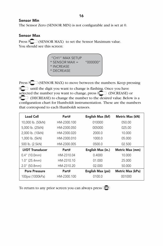
Sensor MinTheSensorZero(SENSORMIN)isnotconfigurableandissetat0.
Sensor Max
Press (SENSORMAX)tosettheSensorMaximumvalue.You should see this screen:
16
“CH1” MAX SETUP * SENSOR MAX = “000000”* INCREASE* DECREASE
Press (SENSORMAX)tomovebetweenthenumbers.Keeppressing
untilthedigityouwanttochangeisflashing.Onceyouhaveselected the number you want to change, press (INCREASE)or
(DECREASE) to change the number to the desired value. Below is a configuration chart for Humboldt instrumentation. These are the numbers that correspond to each Humboldt sensors. Load Cell Part# English Max (lbf) Metric Max (kN)
10,000 lb. (50kN) HM-2300.100 010000 050.00
5,000 lb. (25kN) HM-2300.050 005000 025.00
2,000 lb. (10kN) HM-2300.020 2000.0 10.000
1,000 lb. (5kN) HM-2300.010 1000.0 05.000
500 lb. (2.5kN) HM-2300.005 0500.0 02.500
LVDT Transducer Part# English Max (in.) Metric Max (mm)
0.4" (10.0mm) HM-2310.04 0.4000 10.000
1.0" (25.4mm) HM-2310.10 01.000 25.000
2.0" (50.8mm) HM-2310.20 02.000 50.000
Pore Pressure Part# English Max (psi) Metric Max (kPa)
100psi (1000kPa) HM-2300.100 0100.0 001000
To return to any prior screen you can always press

Calibration
This menu item is used to calibrate or verify the calibration of the HM-1327.
WARNING: Calibration should only be performed by trained personnel with proper, certified equipment. The HM-1327 and its instrumentation should be calibrated once a year or as the need arises.
Input CalibrationTo calibrate a input, press You should see this screen:
Press you will see this screen: Press (ENGINEERINGSETUP).Youshouldseethisscreen:
Press (CALIBRATION)Youwillbeaskedforapassword,enter:
You should see this screen:
* REVIEW LAST TEST* RUN TEST
* MORE SETUP
* ENGINEERING SETUP* SENSOR LIMITS OFF* RAW_DATA* MORE SETUP
* CONFIGURATION* CALIBRATION
17
CALIBRATION screen* SELECT INPUT 1* CALIBRATION INPUT* CLEAR CALIBRATION

18Press (SELECTINPUT)toscrollthroughandchoosethechannelyouwish to calibrate. Once you have chosen the desired channel you wish to calibrate press (CLEARCALIBRATION).
WARNING: IF YOU CLEAR A CALIBRATION IT IS LOST FOREVER! Afterthecalibrationhasbeencleared,Press (CALIBRATECHANNEL)You should see this screen:
Press (SETGAIN).Withtheinstrumentyouwishtocalibratemounted to a calibration frame attached to the HM-1327, record the sensor min value with no load on the instrument (X divisions).
Next,applythefullengineeringloadvaluetoinstrumentonthecalibrationframe and again, record the sensor min reading (X divisions). Subtract the two values. This value should be a number larger than the sensor maximum rating.
Ifnot,youneedtoincreasethegaintocompensateforthedifference.Press
(SETGAIN)andrepeatuntilthedifferencebetweenthetwovaluesismore than the maximum sensor rating.
EXAMPLE:
If you are calibrating a 10,000 lb. load cell, you need a difference value of at least 10,000 divisions. If you register a min value reading of 450 divisions with no load on the sensor and your min is 8450 divisions at full load on the instrument, your difference value will be 8000 divisions. (8450 – 450 = 8000). To increase the gain press (SETGAIN)untilyouhavemorethan 10,000 divisions.
Once the gain has been set, the zero point needs to be set. To set the zero point, apply the 0% force to the sensor and press (SETSENSORMIN). Nowapplythe100%forcetothesensorandpress (SETSENSORMAX).
To return to any prior screen you can always press
On the next page is an Instrumentation calibration chart listing max divisions, as well as typical gain factors needed in calibrating each instrument type.
INPUT CALIBRATION * SET GAIN 1* SET SENSOR MIN 123* SET SENSOR MAX 12345

Humboldt Calibration Instrumentation Chart
19
Load Cell Part# English Gain Metric Gain (divisions) (divisions)
10,000 lb. (50kN) HM-2300.100 10000 4 5000 4
5,000 lb. (25kN) HM-2300.050 5000 2 2500 4
2,000 lb. (10kN) HM-2300.020 20000 8 10000 4
1,000 lb. (5kN) HM-2300.010 10000 4 5000 4
500 lb. (2.5kN) HM-2300.005 5000 4 2500 4
LVDT Transducer
0.4" (10.0mm) HM-2310.04 4000 2 10000 2
1.0" (25.4mm) HM-2310.10 1000 1 25000 2
2.0" (50.8mm) HM-2310.20 2000 1 50000 4
Pore Pressure
100psi (1000kPa) HM-2300.100 1000 1 1000 1
Device ID
Factory set device ID to 1, if multiple units are connect to a single computer a unique device ID for each unit has to be establish for the computer to recognize the correct instrumentation and the correct motors.
To set the Device ID the HM-1327 will use, press until you see this screen:
Press you will see this screen:
Press you will see this screen:
* REVIEW LAST TEST* RUN TEST
* MORE SETUP
* ENGINEERING SETUP* SENSOR LIMITS OFF* RAW_DATA * MORE SETUP
20
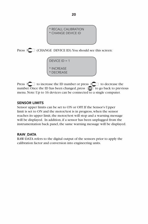
* RECALL CALIBRATION* CHANGE DEVICE ID
Press (CHANGEDEVICEID).Youshouldseethisscreen: Press to increase the ID number or press to decrease the number. Once the ID has been changed, press to go back to previous menu.Note:Upto16devicescanbeconnectedtoasinglecomputer.
SENSOR LIMITS SensorupperlimitscanbesettoONorOFF.IftheSensor’sUpperlimitissettoONandthemotor/testisinprogress,whenthesensorreaches its upper limit, the motor/test will stop and a warning message will be displayed. In addition, if a sensor has been unplugged from the instrumentation back panel, the same warning message will be displayed.
RAW_DATA RAW-DATAreferstothedigitaloutputofthesensorspriortoapplythecalibration factor and conversion into engineering units.
DEVICE ID = 1
* INCREASE* DECREASE

21
Standard Tests
MarshallCenterthebreakingheadontheplaten.Pressthe button to raise the head to the start position, close to the load cell. There should be about a 1/8" (3.000mm) gap between the breaking head and the load cell.
Press You should see this screen:
Press (RUNTEST)Youshouldseethisscreen:
Press (MARSHALL TEST) This will automatically start the platen to rise at a rate of 2.0 in/min (50.8mm/min). You should see this screen:
The display above will give constant real-time readings of the stability and flowmeasurementsduringthetestcycle.Youcanendthetestatanytime
by pressing . This will stop all data collection and reverse the platen to its down position.
As the breaking head makes contact with the load cell, the HM-1327 willautomaticallyzerothestabilityandflowreadingsandbegintotakesreadings every 0.1 seconds. Once the test has reached peak stability (i.e. peak load) and fallen back 2%, data will cease being collected and the platen will begin to reverse and move back to the down position. As the platen moves down, the screen will display the peak values.
* REVIEW LAST TEST* RUN TEST
* MORE SETUP
* MARSHALL TEST* TSR TEST
MARSHALL TEST # of readings STAB “#” FLOW “#”* END TEST

22 You should see this screen:
Peakvaluesareshownonthefirsttwolines.Toreviewallthedata, press (REVIEWDATA).Youshouldseethisscreen: Pressing (PRINTDATA)willprintthedatatoaprinterorsaveafilein ASCII mode to your computer using Humboldt Material testing Software (HMTS)orWindowsHyperterminal.Oncethedatahasbeenprintedor transferred, you can begin another test after you have loaded another sample and raised the head to the start position, close to the load cell. by pressing (RUNMARSHALLTEST).
If you don’t have a printer or a computer connected to the HM-1327, you can press (SCROLL DATA) to scroll the data. You should see this screen:
Using the (NEXT)keytoscrollthroughthereadingsandthe (LAST) key to view the last reading taken.
To return to any prior screen you can always press
TSRSee User-Defined Unconfined Compression, without the displacement transducer selected in the test configuration
STAB PEAK “#” FLOW PEAK “#” REVIEW DATA * RUN MARSHALL TEST
* PRINT DATA * SCROLL DATA * RUN MARSHALL TEST
STAB “READING”FLOW “READING”* NEXT* LAST Time = 0.0 sec

23Software
The HM-1327 comes with Humboldt’s HMTS data collection software. This software can be used to collect data from tests by creating user-defined test parameters (start/stop). The resulting data can then be opened in Microsoft Excel to view the data collected, as well as create a simple table and graph.
Optional pre-defined reporting software modules and templates are available for specific tests, such as CBR, Triaxial, etc. These modules provide more control over start and stop conditions for specific tests, as well as provide extended reporting capabilities. Contact Humboldt for more information.
Table/graph and Excel output of user-defined test generated from software included.
HM Download Software
This software is designed to be used to download test that have been run directly on the HM-1327. It downloads and saves tests directly to a PC. Custom graphs and reports can be generated and exported into multiple formats.

24Specifications
Applicable StandardsCovers: Marshall Tests
ASTM: D6927 and D4123-82
AASHTO: T245 and T283
BS598:Part107
Mechanical SpecificationsDimensions (l x w x h) 17 x 22 x 42 inch (432 x 559 x 1295mm)PlatenTravel 3inches(76mm)Max.NetWeight 206lbs.(94kg)ShippingWeight 300lbs.(660kg)Speed Range 2 inches/min (51mm/min)Loadcapacity 11000lbs.(50kN)Verticalclearance 24inch(610mm)Max.Horizontal clearance 11.5 inch (292mm)
Electrical /Electronics SpecificationsVoltage 110/220VAC50/60HZCurrent 8.5 AmpsAnalog to digital converter 16 BitData storage 4000 ReadingData collection rate 100 msComputer port RS232
Test Accessories
HM-3005—Marshall Stability Accessory Set:HM-2300.100 Loadcell10,000lb.(50kN)HM-2310.10 Displacement Transducer 1.0”(25mm)HM-4178BRT Displacement Transducer Bracket HM-3005SW MarshallReportingSoftware

25
Support
Phonesupportisavailableforgeneraloperatingquestionsandtroubleshootingproblemsbetween8amand5pmEasternTime.Pleasecall:
1.800.537.41831.919.832.6509 or fax: 1.919.833.5283
For sales and sales-related information, such as available accessories, general sales questions, pricing, please call:
1.800.544.72201.708.456.6300 or fax: 1.708.456.0137
Hidden Functions
The following are functions that are possible if needed, to access them, please contact support at the numbers or email address listed above.
1. System reset Reset available in case of serious problem in system memory. This
will cancel all data in memory calibration/configuration of all input channels.

26NOTES

27NOTES


www.humboldtmfg.comHUMBOLDT
Testing Equipment for Construction Materials
Humboldt Mfg. Co.875 Tollgate RoadElgin, Illinois 60123 U.S.A.
U.S.A. Toll Free: 1.800.544.7220 Voice: 1.708.456.6300
Fax: 1.708.456.0137Email: [email protected]
10