Embed Size (px)
Citation preview
1
Humming Bird ELC. Modifications by AIDG/ Xelateco.
Operational Experience at Nueva Alianza
Revision Date Author
B – Second Draft April 2010 Ben Dana
1. Introduction ................................................................................................................................................... 2
2. Micro Hydro Generation at Nueva Alianza: Past and Present ...................................................................... 2
2.1 Three phase generation with three ELCs ................................................................................................. 3
2.2 Generator re-wire for single phase operation .......................................................................................... 4
2.3 A three-phase ELC. ................................................................................................................................. 4
3 PCB manufacture ............................................................................................................................................ 5
3.1 Dust / Environmental Protection ............................................................................................................. 5
3.2 Serial numbers ......................................................................................................................................... 6
4 PCB Modifications ......................................................................................................................................... 6
4.1 Mounting on one board............................................................................................................................ 6
4.2 Protection features removed .................................................................................................................... 7
4.3 Three dump load ELC version................................................................................................................. 7
4.4 Gerber Files ............................................................................................................................................. 7
5 Generator loading by ELC .............................................................................................................................. 7
6. Problems of the AVR mentioned by Dan .................................................................................................. 8
Appendix A ....................................................................................................................................................... 8
ELC Electronic Load Controller
PCB Printed Circuit Board
RPM Revolutions per Minute
KVA Kila-Volt Amps
VAC Voltage (Alternating Current)
Dan Hepler: AIDG Intern during 2008
2
1. Introduction This document gives information on modifications made to the Hummingbird Electronic
Load Controller by Xelateco and its incubator the Appropriate Infrastructure Development
Group (AIDG.) The Hummingbird load control system , designed by Dutch engineer Jan
Portegijs (Portegijs, 2000) is used to regulate a micro-hydro electric system in Comunidad
Nueva Alianza, El Palmar, Quetzaltenango, Guatemala. Rehabilitation of a system built in
the 1930s was undertaken by Xelateco in 2005 and 2006 with the support of AIDG.
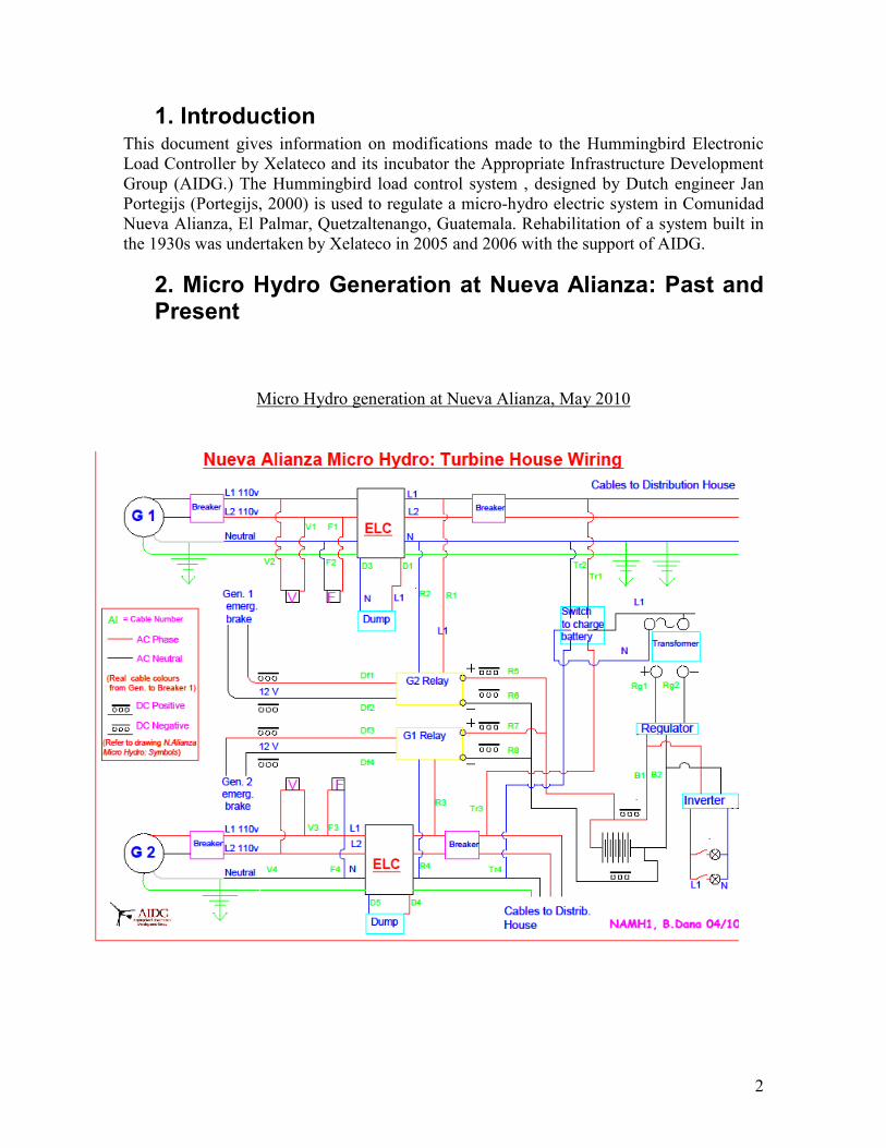
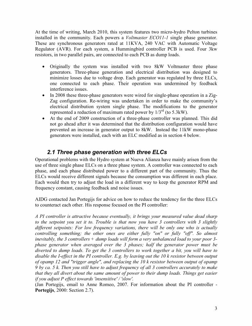
2. Micro Hydro Generation at Nueva Alianza: Past and Present
Micro Hydro generation at Nueva Alianza, May 2010
3
At the time of writing, March 2010, this system features two micro-hydro Pelton turbines
installed in the community. Each powers a Voltmaster ECO11-1 single phase generator.
These are synchronous generators rated at 11KVA, 240 VAC with Automatic Voltage
Regulator (AVR). For each system, a Hummingbird controller PCB is used. Four 3kw
resistors, in two parallel pairs, are connected to each PCB as dump loads.
• Originally the system was installed with two 8kW Voltmaster three phase
generators. Three-phase generation and electrical distribution was designed to
minimize losses due to voltage drop. Each generator was regulated by three ELCs,
one connected to each phase. Their operation was undermined by feedback
interference issues.
• In 2008 these three-phase generators were wired for single-phase operation in a Zig-
Zag configuration. Re-wiring was undertaken in order to make the community’s
electrical distribution system single phase. The modifications to the generator
represented a reduction of maximum rated power by 1/3rd (to 5.3kW).
• At the end of 2009 construction of a three-phase controller was planned. This did
not go ahead after it was determined that the distribution configuration would have
prevented an increase in generator output to 8kW. Instead the 11kW mono-phase
generators were installed, each with an ELC modified as in section 4 below.
2.1 Three phase generation with three ELCs
Operational problems with the Hydro system at Nueva Alianza have mainly arisen from the
use of three single phase ELCs on a three phase system. A controller was connected to each
phase, and each phase distributed power to a different part of the community. Thus the
ELCs would receive different signals because the consumption was different in each place.
Each would then try to adjust the load in a different way to keep the generator RPM and
frequency constant, causing feedback and noise issues.
AIDG contacted Jan Portegijs for advice on how to reduce the tendency for the three ELCs
to counteract each other. His response focused on the PI controller:
A PI controller is attractive because eventually, it brings your measured value dead sharp
to the setpoint you set it to. Trouble is that now you have 3 controllers with 3 slightly
different setpoints: For low frequency variations, there will be only one who is actually
controlling something; the other ones are either fully "on" or fully "off". So almost
inevitably, the 3 controllers + dump loads will form a very unbalanced load to your poor 3-
phase generator when averaged over the 3 phases; half the generator power must be
diverted to dump loads. To get the 3 controllers to work together a bit, you will have to
disable the I-effect in the PI controller. E.g. by leaving out the 10 k resistor between output
of opamp 12 and "trigger angle", and replacing the 10 k resistor between output of opamp
9 by ca. 5 k. Then you still have to adjust frequency of all 3 controllers accurately to make
that they all divert about the same amount of power to their dump loads. Things get easier
if you adjust P effect towards 'insensitive' / 'slow'.
(Jan Portegijs, email to Anne Romeo, 2007. For information about the PI controller -
Portegijs, 2000: Section 2.7).
4
Subsequently the “I-effect” was reduced to minimum at Nueva Alianza to minimise the
PCBs working against each other. This reduced the problems, but did not eliminate them.
Other problems at Nueva Alianza, such as frequent tripping of over-current protection,
would have been partly due to failure to balance the loads on each phase and generator
under-sizing; outlined by Portegijs, 2000, K3:
If proper load balancing can not be guaranteed, the generator and wiring must be
overrated and/or the over-current protection will trip often… [Without proper load
balancing] the generator could overheat because one stator phase carries way too much
current. Also user loads might be damaged because of under-voltage at the heavily loaded
line(s), or overvoltage at the lightly loaded line(s)…To reduce unbalance problems, all
heavy loads should be 3-phase ones. This means that large single phase electrical motors
can not be allowed on a 3-phase system.
The positioning of transformers in the distribution network was designed to address load
balancing issues by connecting relatively equal loads to each phase. However the network
was unbalanced with L1 usually more heavily charged than the other two lines. L1 powered
11 houses including the hotel, the office, the school (the ‘casco’) and the houses at the
bottom of the community. L2 and L3 each powered about 5-6 houses, higher up in the
community.
The original system design also tried to prevent generator overloading by the use of 1A
fuses for each house. However these were unpopular as they blew frequently (e.g. when the
T.V. was switched on) and were thus occasionally bypassed. They were replaced by 2A
fuses which allowed for the higher startup loads of some appliances.
2.2 Generator re-wire for single phase operation
As an attempt to completely eliminate the controller feedback issues, the generator and
distribution network were modified for single phase operation in 2008. This reduced
maximum rated power of the generators from 8kW to 5.3kW. At the time total dump load
capacity connected to each generator was 6kW. With the generator's ELC active before
connecting to the community, 6kW of power would be dissipated into the dump loads.
Once user loads in the community were switched on, more water flow
would be required to maintain operation at 60Hz. This would mean that the generator
would be working at least at 113% of its rated maximum, significantly reducing generator
life.
In addition this change increased the problems created by heavy user loads connected to
this generator. The under-voltage protection feature of the ELC was activated more often
due to the community having a higher demand than the generators were able to handle.
2.3 A three-phase ELC.
In 2009 AIDG and Xelateco evaluated manufacturing a 3 phase version of the ELC to
allow the generators to work at 8Kw (the modifications required are outlined by Portegijs,
5
2000, K3.) This would have required returning to a three phase distribution network, and
balancing the loads served by each phase in the community. However, it was determined
that the current distribution system would not have prevented an increase in the 5.7kW
generator output; 3 phases feeding 2 high voltage transformers; with the 2 x 13kV
transmission lines then transformed into 3 x 220V distribution cables. The distribution
network would have to be upgraded with 2 additional transformers and an additional
transmission line. Also, the continued geographical unbalance of loads within the
community (large loads are all located in one center spot) would make proper balancing a
challenge. Upon complete evaluation, the expense and complexity of this option was
deemed to be greater than that of purchasing new single phase generators.
Avoidance of a three phase controller in the past also reflects the general lack of experience
with a 3 phase ELC. Portegijs acknowledges that a three phase version was yet to be tested
during his publication in 2000.
3 PCB manufacture Portegijs (2000) gives guidelines for making PCBs in Section 7.1 of his manual. He also
suggests having the ELC made professionally by an electronics workshop. However the
ELC designs presented in the manual are available only as image files, not as ‘gerbers’; this
complicates professional manufacture, and makes it difficult to represent and reproduce
modified versions.
Originally the circuit boards for Nueva Alianza were made with a clothes iron. Although
their quality was reasonable it was only possible to make one sided PCBs in this way,
meaning many wires were needed within the circuit board to make connections. Although
the original board had pads on each side, according to Portegijs this is legitimate: ‘`Long-
distance’ print tracks on component side must be replaced by wire bridges. Such wire
bridges can not branch out to connect several points so there are extra diamond-shaped
islands on copper side to fit separate wire bridges to all points that have to be connected to
one another.’
However this method of manufacture resulted in problems with Electro-Magnetic
Interference (EMI)
As an alternative to this Protegijs also suggests, ‘a double-sided PCB made by gluing
two thin, single-sided PCB's together using epoxy glue.’ This was not attempted by
Xelateco/ AIDG.
Later prototypes were made professionally on double sided circuit boards.
3.1 Dust / Environmental Protection
The PCBs themselves are protected against dust with a clear acrylic spray after basic
testing. New PCBs should be soldered with SK10 compound anti-oxidation solder flux as
recommended in Portegijs’ manual. Dan Hepler recommended the inclusion of a
6
soldermask layer on the PCB for environmental protection and solderability, but this type
of manufacturing is not available in Guatemala.
The ELC housing has been improved although it possibly wouldn’t meet the IP55 standard
specified by Portegijs. For example holes drilled into the enclosures for conduit maybe
slightly larger than pipe diameter. In April 2010 mice were found in the circuit breaker
enclosure in the Distribution House.
3.2 Serial numbers
AIDG/ Xelateco do not assign serial numbers to the circuit boards made. This means that
they can only be identified by the few people who built them. It is not possible to know
what substitutes were made or what issues exist with certain boards. It is difficult to record
calibration values or find a unit’s history.
It is recommended that all units (circuit boards, systems, etc) should be assigned a serial
number. Manufacturing, calibration, and maintenance information should record the serial
number to which they pertain. Additionally, sales orders or invoices should contain the
serial number.
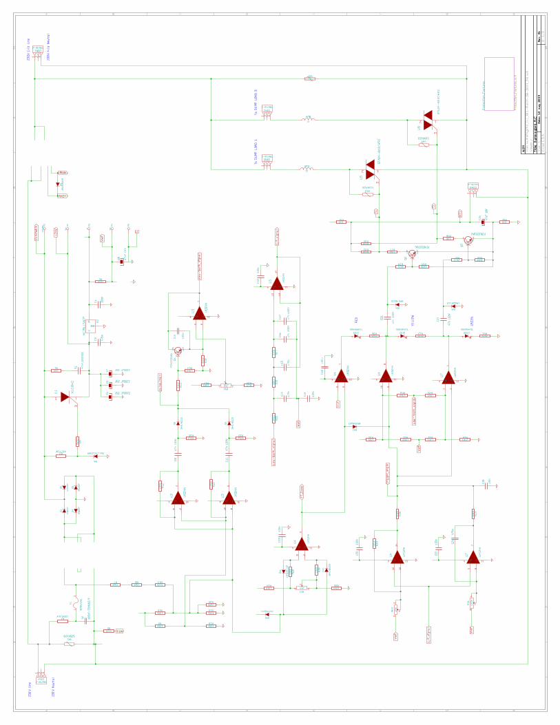
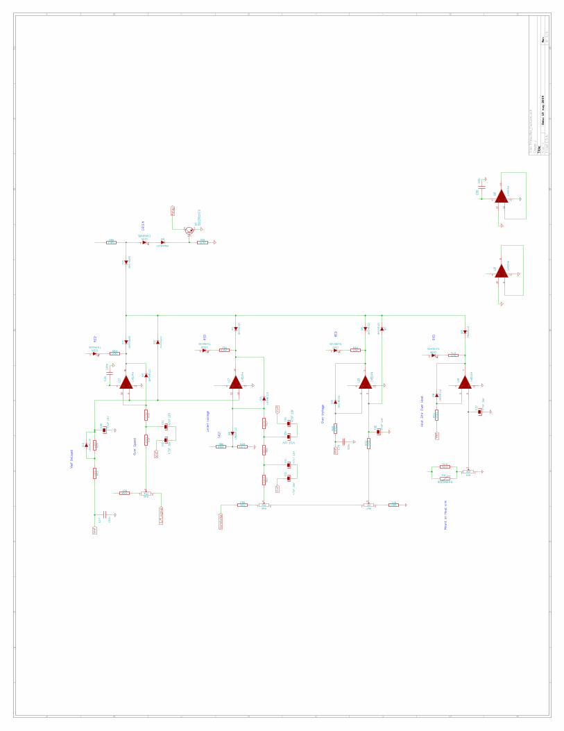
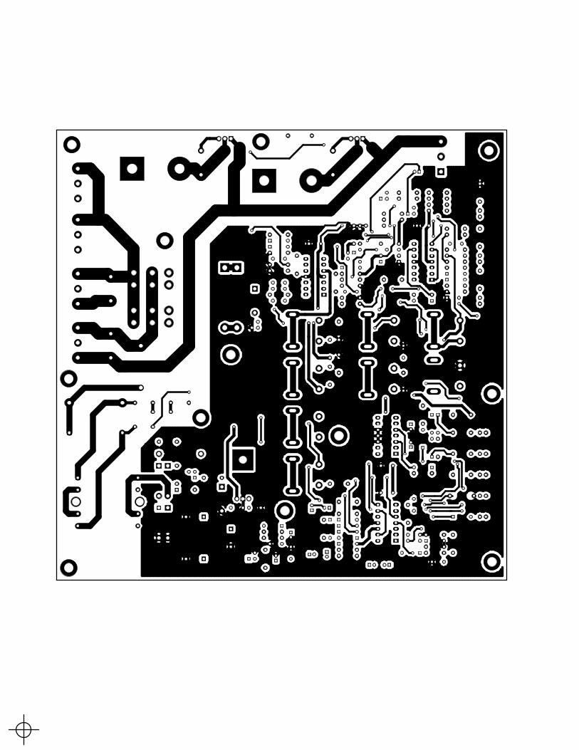
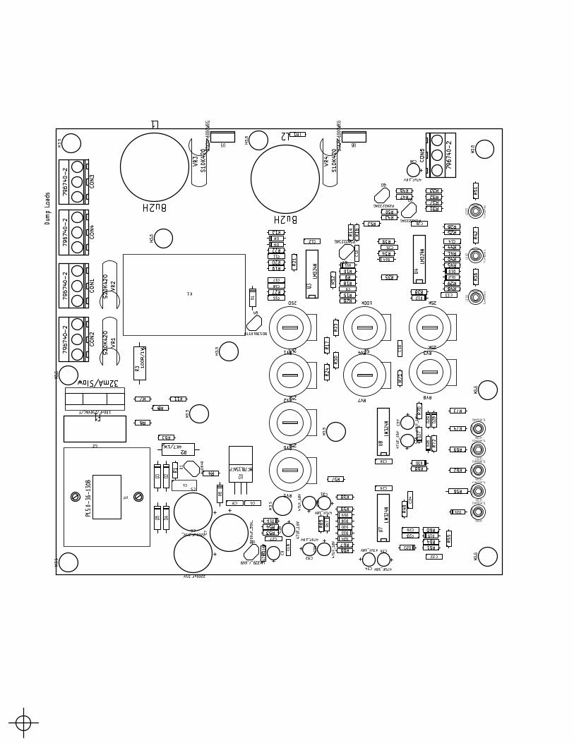
4 PCB Modifications
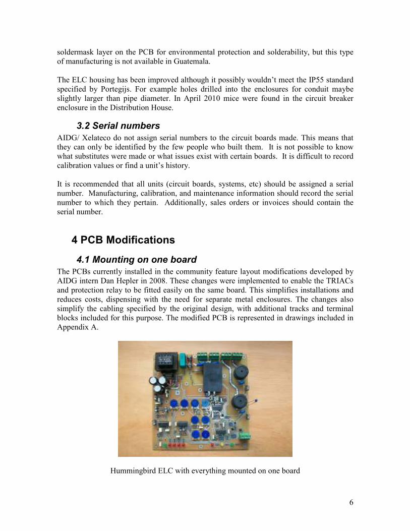
4.1 Mounting on one board
The PCBs currently installed in the community feature layout modifications developed by
AIDG intern Dan Hepler in 2008. These changes were implemented to enable the TRIACs
and protection relay to be fitted easily on the same board. This simplifies installations and
reduces costs, dispensing with the need for separate metal enclosures. The changes also
simplify the cabling specified by the original design, with additional tracks and terminal
blocks included for this purpose. The modified PCB is represented in drawings included in
Appendix A.
Hummingbird ELC with everything mounted on one board
7
4.2 Protection features removed
Dan Hepler’s modifications also omitted the Overload Signal (Porgegijs, 2000, Section
2.8.) Experiences in Nueva Alianza had shown it to be almost redundant there. System
users would not respond to the low frequency dimming of the lights by turning off
electronic devices to reduce load, in partly due to the frequency of operational problems in
the first years of the hydro-electrical rehabilitation. It was left out therefore, to simplify the
ELC.
4.3 Three dump load ELC version.
Portegijs’ design allows the ELC to be built with two or three dump loads. For use with
three dump loads, the PCBs for N.A. include the all components represented in graphic 23
of his manual: those printed normally and those underscored (the underscored components
are necessary for the 3 dump load version. More details are available in (Portegijs, 2000,
Section 7.1.1).
Furthermore only the components drawn in black are fitted, those printed in red pertaining
to the IGC version. The IGC area of the PCB is omitted. A separate IGC circuit board is
being currently developed by AIDG.
4.4 Gerber Files
The redesigned ELC has been represented by Dan Hepler in Gerber file format so that any
PCB manufacturer could reproduce it.
5 Generator loading by ELC Phase-angle regulation of triac-controlled dump loads introduces significant voltage dips to
the mains voltage. This ‘rattling’ effect causes more wear on the generator bearings than a
constant load. Turning on current later in the sine waveform (after the zero-crossing)
reduces the power factor by acting like a lagging load. This means more reactive current
relative to the real current, which is loading the generators more. The voltage dips cause the
generator to turn on suddenly constituting a sudden torque on the generator.
The effect is mitigated somewhat by having more dump loads connected in parallel (two
rather than three.)
The additional loading caused by the triacs can cause problems of false triggering (power
diverted to the dump loads when it doesn’t need to be, or not diverted when it should be.)
An ELC that used pulse width modulation (PWM) with IGBTs or MOSFETs could provide
a power factor corrected load which would dramatically reduce the noise and loading on the
8
generators. This would merit future investigation by AIDG or other organizations working
with installations of the kind.
6. Problems of the AVR mentioned by Dan Hepler
Under high head conditions the ELC may send all the power to the dump loads. The
generator would speed up and frequency would rise. However with the generator above
its100% rated capacity the AVR would reduce the voltage. With a lower electrical load the
turbine speeds up significantly.
This may trip the over speed protection causing system shut-down. Alternatively however
the result may be for the AVR to increase voltage, causing oscillation.
Appendix A Modified PCB drawings by Dan Hepler