Embed Size (px)
Citation preview

Hunter Woron
Spring 2012
Structural
Professor Parfitt
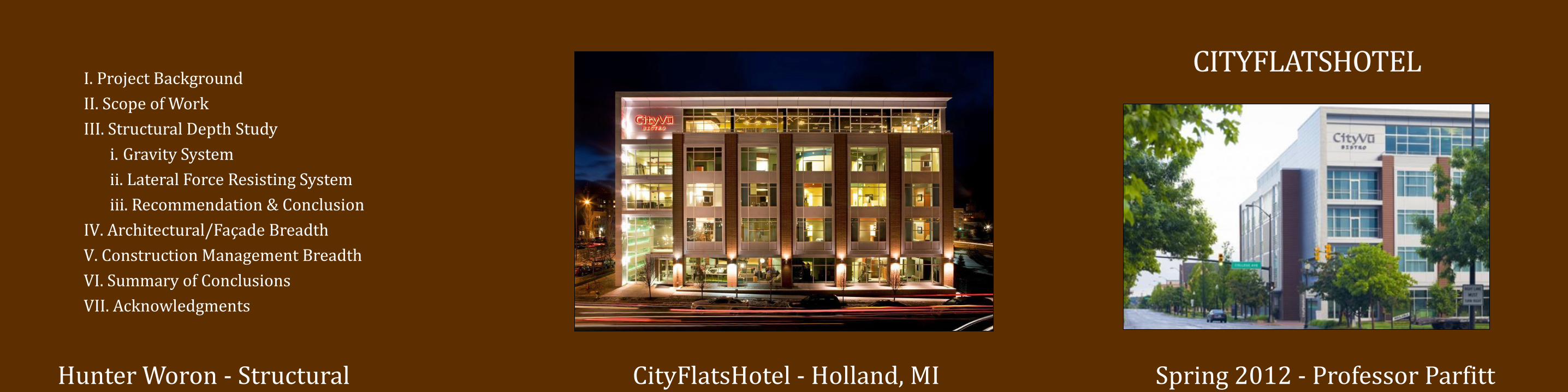
CITYFLATSHOTEL
I. Project Background
II. Scope of Work
III. Structural Depth Study
i. Gravity System
ii. Lateral Force Resisting System
iii. Recommendation & Conclusion
IV. Architectural/Façade Breadth
V. Construction Management Breadth
VI. Summary of Conclusions
VII. Acknowledgments

Project Background
I. Project Background
II. Scope of Work
III. Structural Depth Study
i. Gravity System
ii. Lateral Force Resisting System
iii. Recommendation & Conclusion
IV. Architectural/Façade Breadth
V. Construction Management Breadth
VI. Summary of Conclusions
VII. Acknowledgments
Location: Downtown Holland Michigan
Intersection of 7th Street and College Ave
Function: Eco-Boutique Hotel with 56 Guestrooms
Restaurant, Fitness Center, Cinema Room,
Bar & Lounge
Building 65,000 Square Feet
Statistics: 5 Stories Above Grade
Overall Height of 67’-2”

Project Background
I. Project Background
II. Scope of Work
III. Structural Depth Study
i. Gravity System
ii. Lateral Force Resisting System
iii. Recommendation & Conclusion
IV. Architectural/Façade Breadth
V. Construction Management Breadth
VI. Summary of Conclusions
VII. Acknowledgments
Owner: Charter House Innovations
Contract: Design-Build Delivery Method
Architect / GMB Architecture + Engineering
Engineer:
Construction GDK Construction
Manager: Cost: $7.2 Million
Schedule: February 2007 to February 2008

Project Background
I. Project Background
II. Scope of Work
III. Structural Depth Study
i. Gravity System
ii. Lateral Force Resisting System
iii. Recommendation & Conclusion
IV. Architectural/Façade Breadth
V. Construction Management Breadth
VI. Summary of Conclusions
VII. Acknowledgments
Foundation: 4” Concrete Slab
Gravity System: CMU Load Bearing Walls
8” Precast Hollow Core Planking
w/ 2” Concrete Topping
Steel Members Where Required
Lateral System: Reinforced Concrete Masonry
Shear Walls
Typically 8” or 12” Thick CMU
Existing Structural System

Scope of Work
I. Project Background
II. Scope of Work
III. Structural Depth Study
i. Gravity System
ii. Lateral Force Resisting System
iii. Recommendation & Conclusion
IV. Architectural/Façade Breadth
V. Construction Management Breadth
VI. Summary of Conclusions
VII. Acknowledgments
Project Statement:
Existing Structural System is the Most
Efficient and Economical
Design a Viable Alternative System
Project Solution:
Girder-Slab Composite Steel and
Precast System

Scope of Work
I. Project Background
II. Scope of Work
III. Structural Depth Study
i. Gravity System
ii. Lateral Force Resisting System
iii. Recommendation & Conclusion
IV. Architectural/Façade Breadth
V. Construction Management Breadth
VI. Summary of Conclusions
VII. Acknowledgments
Structural Depth: Reduce Overall Building Weight
Optimize Gravity and Lateral Systems
Verify Impact on Foundation
Architectural / Façade Breadth:
Research Various Façade Options
Address Thermal and Sound Effects
Construction Management Breadth:
Impact on Overall Schedule and Cost
Project Goals

Structural Depth Study
I. Project Background
II. Scope of Work
III. Structural Depth Study
i. Gravity System
ii. Lateral Force Resisting System
iii. Recommendation & Conclusion
IV. Architectural/Façade Breadth
V. Construction Management Breadth
VI. Summary of Conclusions
VII. Acknowledgments
Gravity System:
Composite Steel and Precast System
Lightweight
Offers Quick Construction
Increases Overall Building Height
Requires Fireproofing
Design Loads
Area GMB Design Loads (PSF) ASCE 7-05 Load (PSF) Design Load (PSF)
Private Guest Rooms 40 40 40
Public Spaces 100 100 100
Corridors 10040 (Private Corridor) /
100 (Public Corridor)
40 (Private Corridor) /
100 (Public Corridor)
Lobbies 100 100 100
Stairs 100 100 10
Storage/Mechanical 125 125 (Light) 125
Theater (Fixed) 60 60 60
Restaurant/Bar 100 100 100
Patio (Exterior) 100 100 100
Material GMB Design Loads (PSF) ASCE 7-05 Load (PSF) Design Load (PSF)
8" Precast w/ Topping Unknown 81
Steel Unknown Varies
Partitions Unknown 10
MEP Unknown 10
Finishes/Miscellaneous Unknown 5
Roof Unknown 20
Area GMB Design Loads (PSF) ASCE 7-05 (PSF) Design Load (PSF)
Flat Roof 35 35 35
Section 3.1
Live Loads (LL)
Dead Loads (DL)
Snow Load (SL)

Structural Depth Study
I. Project Background
II. Scope of Work
III. Structural Depth Study
i. Gravity System
ii. Lateral Force Resisting System
iii. Recommendation & Conclusion
IV. Architectural/Façade Breadth
V. Construction Management Breadth
VI. Summary of Conclusions
VII. Acknowledgments
Framing Plan:
Typical Bay Size - 18’ x 24’
Beam Size: W18x40
Columns Aligned with Partition Walls
Increased Floor-to-Ceiling Height
Controlling Load Combination:
1.2D + 1.6L + 0.5Lr Deflection Live Load: L/360
Criteria: Total Load: L/240
Typical Floor Plan Layout
Framing Plan

Structural Depth Study
I. Project Background
II. Scope of Work
III. Structural Depth Study
i. Gravity System
ii. Lateral Force Resisting System
iii. Recommendation & Conclusion
IV. Architectural/Façade Breadth
V. Construction Management Breadth
VI. Summary of Conclusions
VII. Acknowledgments
Column Design:
Comply with LRFD methods and AISC Steel Manual
Optimal Members Designed by ETABS
Resist Gravity Loads Only
Typical Size - W8x31
Typical Section of Structural Components

Structural Depth Study
I. Project Background
II. Scope of Work
III. Structural Depth Study
i. Gravity System
ii. Lateral Force Resisting System
iii. Recommendation & Conclusion
IV. Architectural/Façade Breadth
V. Construction Management Breadth
VI. Summary of Conclusions
VII. Acknowledgments
Pre-Cast Plank Design:
Live Load: 40 PSF
Dead Load: 15 PSF
Superimposed Dead: 25 PSF
PCI Design Handbook Results: 66-S Strands 6 Strands @ 6/16” Diameter Self Weight of 81 PSF

Structural Depth Study
I. Project Background
II. Scope of Work
III. Structural Depth Study
i. Gravity System
ii. Lateral Force Resisting System
iii. Recommendation & Conclusion
IV. Architectural/Façade Breadth
V. Construction Management Breadth
VI. Summary of Conclusions
VII. Acknowledgments
Assumptions and Considerations:
Modeled Lateral Members Only
Columns Pinned at Base
Beams and Braces Pinned
Floor Diaphragms Modeled as Rigid Elements
Accidental and Inherent Torsion was Considered
Lateral Force Resisting System:

Structural Depth Study
I. Project Background
II. Scope of Work
III. Structural Depth Study
i. Gravity System
ii. Lateral Force Resisting System
iii. Recommendation & Conclusion
IV. Architectural/Façade Breadth
V. Construction Management Breadth
VI. Summary of Conclusions
VII. Acknowledgments
Wind / Seismic Effects:
Design Wind and Seismic Load Cases Were Used
1.2D + 1.6 WY + 1.0L + 0.5Lr
0.9D + 1.0EX
Wind / Seismic Drifts:
Drift Criteria:
Wind - H/400
Seismic - 0.02HSX
Level
Height
Above
Ground, h
(ft)
Allowable
Drift
Δallowable
= h/400
Total Drift
(X-Direction)
Total Drift
(Y-Direction)Adequate
Roof 74.92 2.25 1.11 1.53 Yes
Level 5 58.00 1.74 0.84 1.13 Yes
Level 4 44.00 1.32 0.60 0.81 Yes
Level 3 30.00 0.90 0.38 0.51 Yes
Level 2 16.00 0.48 0.19 0.29 Yes
Level 1 0.00 0.00 0.00 0.00 Yes
Controlling Wind Drift
Level
Height of
Story, h
(ft)
Allowable
Story Drift
Δallowable
= 0.02hsx
Total Drift
(X-Direction)
Total Drift
(Y-Direction)Adequate
Roof 16.92 0.34 0.0085 0.026 Yes
Level 5 14.00 0.28 0.0056 0.017 Yes
Level 4 14.00 0.28 0.0056 0.014 Yes
Level 3 14.00 0.28 0.0056 0.010 Yes
Level 2 14.00 0.28 0.0042 0.008 Yes
Level 1 16.00 0.32 0.0011 0.002 Yes
Controlling Seismic Drift
Existing Building Design New Building Design
Building Weight 10258 kips 7913 kips
Base Shear 463.7 kips 200 kips
Total Moment 15745 ft-k 7983 ft-k
Seismic Comparison

Structural Depth Study
I. Project Background
II. Scope of Work
III. Structural Depth Study
i. Gravity System
ii. Lateral Force Resisting System
iii. Recommendation & Conclusion
IV. Architectural/Façade Breadth
V. Construction Management Breadth
VI. Summary of Conclusions
VII. Acknowledgments
Impact on Foundation: Impact of Lateral Loads:
Overturning NOT a Concern - Gravity Loads Much Larger
Lateral Force Fx
(k)
Total Moment
Mx (ft-k)
Lateral Force Fx
(k)
Total Moment
mx (ft-k)
Top of Roof 77.17 2.25 4.0 0.0 - -Roof 74.92 16.92 34.3 77.2 17.4 1173.9
Fifth 58.00 14.00 54.4 997.7 74.9 3818.1
Fourth 44.00 14.00 47.5 1662.8 55.1 2037.5
Third 30.00 14.00 45.7 2302.5 35.5 815.8
Second 16.00 14.00 43.1 2906.0 17.2 137.9
Firs t 0.00 16.00 20.8 3196.9 0.0 0.0
Total= 249.8 11143.1 200.0 7983.2
E/W Seismic Forces
Overturning Moments
FloorHeight Above
Ground Z (ft)
Story Height
(ft)
N/S Wind Forces

Structural Depth Study
I. Project Background
II. Scope of Work
III. Structural Depth Study
i. Gravity System
ii. Lateral Force Resisting System
iii. Recommendation & Conclusion
IV. Architectural/Façade Breadth
V. Construction Management Breadth
VI. Summary of Conclusions
VII. Acknowledgments
Structural Recommendation:
Viable Option as an Alternative Structural System
Structural Conclusion:
Steel Structure Sufficiently Designed for Strength
and Serviceability Requirements
Reduced the Overall Building Weight
Reduced Base Shear and Overturning Moment
Increase Floor-to-Ceiling Height
Increase Overall Building Height
Avoided Major Architectural Changes / Impacts
Architectural/Façade Breadth
I. Project Background
II. Scope of Work
III. Structural Depth Study
i. Gravity System
ii. Lateral Force Resisting System
iii. Recommendation & Conclusion
IV. Architectural/Façade Breadth
V. Construction Management Breadth
VI. Summary of Conclusions
VII. Acknowledgments
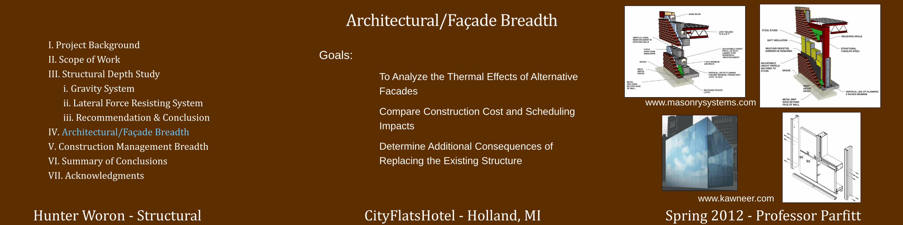
Goals:
To Analyze the Thermal Effects of Alternative
Facades
Compare Construction Cost and Scheduling
Impacts
Determine Additional Consequences of
Replacing the Existing Structure
www.masonrysystems.com
www.kawneer.com

Architectural/Façade Breadth
I. Project Background
II. Scope of Work
III. Structural Depth Study
i. Gravity System
ii. Lateral Force Resisting System
iii. Recommendation & Conclusion
IV. Architectural/Façade Breadth
V. Construction Management Breadth
VI. Summary of Conclusions
VII. Acknowledgments
Thermal Gradients:
1.Brick 2. Cavity 3. Insulation
4. CMU Block 5. Gyp Wall Board

Architectural/Façade Breadth
I. Project Background
II. Scope of Work
III. Structural Depth Study
i. Gravity System
ii. Lateral Force Resisting System
iii. Recommendation & Conclusion
IV. Architectural/Façade Breadth
V. Construction Management Breadth
VI. Summary of Conclusions
VII. Acknowledgments
Cost and Time Comparison:
Wall System S.F. Crew SizeMaterial Cost /
SF
Labor Cost /
SFTotal Cost
Daily
Output (SF)
Construction
Time (Days)
CMU/Brick
System8041
3 Bricklayers, 3
Bricklayer
Helpers
$7.65 $14.90 $181,325 130 62
Wall System S.F. Crew SizeMaterial Cost /
SF
Labor Cost /
SFTotal Cost
Daily
Output
Construction
Time
Brick Vaneer
System /
Metal Stud
Backup
9183
3 Bricklayers, 2
Bricklayer
Helpers
$6.60 $11.60 $167,131 220 42
Curtain Wall
System9183
2 Glazers, 2
Structural Steel
Workers
$24.50 $8.85 $306,253 205 45
Façade of Exisiting System
Façade Comparisions
Façade Systems for Redesigned System
Additional Concerns:
Acoustics:
Noise Limitations Important in Hotel
Sound Absorbing Panels
Hanging Ceilings
Various Floor Coverings
Multiple Layers of Gypsum Wall Board

Construction Management Breadth
I. Project Background
II. Scope of Work
III. Structural Depth Study
i. Gravity System
ii. Lateral Force Resisting System
iii. Recommendation & Conclusion
IV. Architectural/Façade Breadth
V. Construction Management Breadth
VI. Summary of Conclusions
VII. Acknowledgments
Construction Schedule Impact:
Existing Structural System:
Start Date: March 23, 2007
End Date: August 23, 2007
Redesigned Structural System:
Start Date: March 23, 2007
End Date: July 26, 2007
Existing Schedule
Redesigned Schedule

Construction Management Breadth
I. Project Background
II. Scope of Work
III. Structural Depth Study
i. Gravity System
ii. Lateral Force Resisting System
iii. Recommendation & Conclusion
IV. Architectural/Façade Breadth
V. Construction Management Breadth
VI. Summary of Conclusions
VII. Acknowledgments
Overall Cost Impact:
Shearwalls Amount UnitMaterial
Cost/Unit
Labor Cost
/Unit
Equipment
Cost/Unit
Total
Cost/Unit
Total Cost
w/O&PTotal Cost
8" CMU, reinforced 59500 SF 2.15 2.71 - 4.86 6.85 $407,575
12" CMU, reinforced 28500 SF 3.11 4.16 - 7.27 10.30 $293,550
Steel Amount UnitMaterial
Cost/Unit
Labor Cost
/Unit
Equipment
Cost/Unit
Total
Cost/Unit
Total Cost
w/O&PTotal Cost
Columns 1400 LF 41.50 2.78 2.86 47.14 54.00 $75,600
Baseplates 140 SF 21.00 - - 21.00 23.00 $3,220
Beams 1945 LF 12.30 2.09 2.15 16.54 19.90 $38,706
Fireproofing 10420 SF 0.45 0.38 0.08 0.91 1.21 $12,608
$831,259
Cost Estimate of Existing System
Total Cost of Existing System:
Shearwalls Amount UnitMaterial
Cost/Unit
Labor Cost
/Unit
Equipment
Cost/Unit
Total
Cost/Unit
Total Cost
w/O&PTotal Cost
12" CMU, reinforced 23500 SF 2.15 2.71 - 4.86 6.85 $160,975
Steel Amount UnitMaterial
Cost/Unit
Labor Cost
/Unit
Equipment
Cost/Unit
Total
Cost/Unit
Total Cost
w/O&PTotal Cost
Columns 6300 LF 41.50 2.78 2.86 47.14 54.00 $340,200
Baseplates 520 SF 21.00 - - 21.00 23.00 $11,960
Beams 6750 LF 12.30 2.09 2.15 16.54 19.90 $134,325
Braces 2500 LF 31.00 28.50 - 59.50 82.5 $206,250
Fireproofing 31300 SF 0.45 0.38 0.08 0.91 1.21 $37,873
$891,583
Cost Estimate of Redesigned System
Total Cost of Redesigned System:
ComponentExisting
System
Redesigned
SystemAdditional Cost
CMU Walls $701,125 $160,975 -$540,150
Steel Bracing $0 $206,250 $206,250
Steel Framing $130,134 $524,358 $394,224
Total $831,259 $891,583 $60,324
Overall Cost Comparison

Summary of Conclusions
I. Project Background
II. Scope of Work
III. Structural Depth Study
i. Gravity System
ii. Lateral Force Resisting System
iii. Recommendation & Conclusion
IV. Architectural/Façade Breadth
V. Construction Management Breadth
VI. Summary of Conclusions
VII. Acknowledgments
Architectural / Façade Conclusions:
Brick Veneer System Most Efficient
Additional Acoustical Elements Required
Construction Management Conclusions
Reduced Schedule Period
Minimal Increase of Up Front Cost
Structural Conclusion:
Steel Structure Sufficiently Designed for Strength
and Serviceability Requirements
Reduced the Overall Building Weight
Reduced Base Shear and Overturning Moment
Increase Floor-to-Ceiling Height
Increase Overall Building Height
Avoided Major Architectural Changes / Impacts

Acknowledgments
I. Project Background
II. Scope of Work
III. Structural Depth Study
i. Gravity System
ii. Lateral Force Resisting System
iii. Recommendation & Conclusion
IV. Architectural/Façade Breadth
V. Construction Management Breadth
VI. Summary of Conclusions
VII. Acknowledgments
Charter House Innovations:
• Chuck Reid
CityFlatsHotel:
• Sara Lilly
GDK Construction:
• Kara Slater
GMB Architecture + Engineering
The Pennsylvania State University:
•Professor Kevin Parfitt
•Professor Robert Holland
•The Entire AE Faculty and Staff
All my friends, family, and classmates for their unconditional support and encouragement.
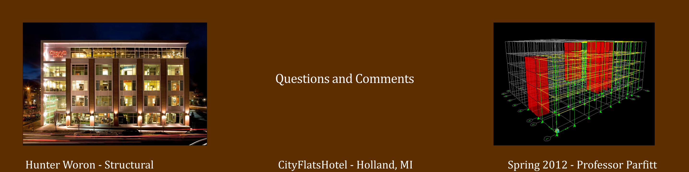
Questions and Comments