Embed Size (px)
Citation preview
Hurricane and High Wind FansModels: G, GB, CUE, CUBE, S-CUBE, USGF, R, RB, FGI, FGR, LBP, LDP, RSF, RSFP SWB, SFB and SFD
March 2010

2
As the first fan manufacturer to certify products to hurricane standards, Greenheck is committed to offering the widest selection of hurricane rated ventilation products in the industry. From fans and laboratory exhaust systems to louvers and louvered penthouses, Greenheck's hurricane products are all third-party certified and designed to out-perform the competition.
Product Features include:
All standard models are hurricane certifies
Highest industry rating
Fans are certified for static and cyclic wind loading and missile impact
Designed to withstand wind loads of up to 150 mph
No tie downs are needed
Installation/mounting details are provided
Greenheck fans are engineered and constructed to withstand severe conditions. These durable fans are easy to mount and install and will provide years of reliable, worry free service in high wind environments.
At Greenheck, we provide just what you need to meet the challenges for high winds and hurricanes.
Overview
Third-party Certified High Wind and Hurricane Fans
Certifications
3
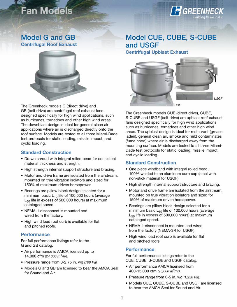
The Greenheck models G (direct drive) and GB (belt drive) are centrifugal roof exhaust fans designed specifically for high wind applications, such as hurricanes, tornadoes and other high wind areas. The downblast design is ideal for general clean air applications where air is discharged directly onto the roof surface. Models are tested to all three Miami-Dade test protocols for static loading, missile impact, and cyclic loading.
Standard Construction• Drawn shroud with integral rolled bead for consistent
material thickness and strength.
• High strength internal support structure and bracing.
• Motor and drive frame are isolated from the airstream, mounted on true vibration isolators and sized for 150% of maximum driven horsepower.
• Bearings are pillow block design selected for a minimum basic L10 life of 100,000 hours (average L50 life in excess of 500,000 hours) at maximum cataloged speed.
• NEMA-1 disconnect is mounted and wired from the factory.
• High wind load roof curb is available for flat and pitched roofs.
Performance For full performance listings refer to the G and GB catalog.
• Air performance is AMCA licensed up to 14,000 cfm (24,000 m3/hr).
• Pressure range from 0-2.75 in. wg (700 Pa).
• Models G and GB are licensed to bear the AMCA Seal for Sound and Air.
Standard Construction• One piece windband with integral rolled bead,
100% welded to an aluminum curb cap (steel with non-stick material for USGF).
• High strength internal support structure and bracing.
• Motor and drive frame are isolated from the airstream, mounted on true vibration isolators and sized for 150% of maximum driven horsepower.
• Bearings are pillow block design selected for a minimum basic L10 life of 100,000 hours (average L50 life in excess of 500,000 hours) at maximum cataloged speed.
• NEMA-1 disconnect is mounted and wired from the factory (NEMA-3R for USGF).
• High wind load roof curb is available for flat and pitched roofs.
Performance For full performance listings refer to the CUE, CUBE, S-CUBE and USGF catalog.
• Air performance AMCA licensed from 400-15,000 cfm (25,000 m3/hr).
• Pressure range from 0-5 in. wg (1,250 Pa).
• Models CUE, CUBE, S-CUBE and USGF are licensed to bear the AMCA Seal for Sound and Air.
The Greenheck models CUE (direct drive), CUBE, S-CUBE and USGF (belt drive) are upblast roof exhaust fans designed specifically for high wind applications such as hurricanes, tornadoes and other high wind areas. The upblast design is ideal for restaurant (grease laden), general clean air, smoke and mild contaminates (fume hood) where air is discharged away from the mounting surface. Models are tested to all three Miami-Dade test protocols for static loading, missile impact, and cyclic loading.
Fan Models
Model G and GB Centrifugal Roof Exhaust
Model CUE, CUBE, S-CUBE and USGF Centrifugal Upblast Exhaust
USGF
CUE
4
Fan Models
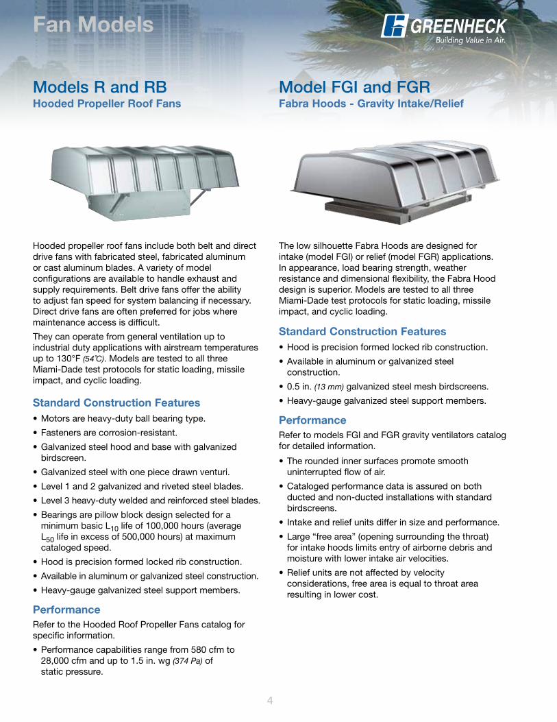
The low silhouette Fabra Hoods are designed for intake (model FGI) or relief (model FGR) applications. In appearance, load bearing strength, weather resistance and dimensional flexibility, the Fabra Hood design is superior. Models are tested to all three Miami-Dade test protocols for static loading, missile impact, and cyclic loading.
Standard Construction Features• Hood is precision formed locked rib construction.
• Available in aluminum or galvanized steel construction.
• 0.5 in. (13 mm) galvanized steel mesh birdscreens.
• Heavy-gauge galvanized steel support members.
PerformanceRefer to models FGI and FGR gravity ventilators catalog for detailed information.
• The rounded inner surfaces promote smooth uninterrupted flow of air.
• Cataloged performance data is assured on both ducted and non-ducted installations with standard birdscreens.
• Intake and relief units differ in size and performance.
• Large “free area” (opening surrounding the throat) for intake hoods limits entry of airborne debris and moisture with lower intake air velocities.
• Relief units are not affected by velocity considerations, free area is equal to throat area resulting in lower cost.
Model FGI and FGRFabra Hoods - Gravity Intake/Relief
Standard Construction Features• Motors are heavy-duty ball bearing type.
• Fasteners are corrosion-resistant.
• Galvanized steel hood and base with galvanized birdscreen.
• Galvanized steel with one piece drawn venturi.
• Level 1 and 2 galvanized and riveted steel blades.
• Level 3 heavy-duty welded and reinforced steel blades.
• Bearings are pillow block design selected for a minimum basic L10 life of 100,000 hours (average L50 life in excess of 500,000 hours) at maximum cataloged speed.
• Hood is precision formed locked rib construction.
• Available in aluminum or galvanized steel construction.
• Heavy-gauge galvanized steel support members.
PerformanceRefer to the Hooded Roof Propeller Fans catalog for specific information.
• Performance capabilities range from 580 cfm to 28,000 cfm and up to 1.5 in. wg (374 Pa) of static pressure.
Hooded propeller roof fans include both belt and direct drive fans with fabricated steel, fabricated aluminum or cast aluminum blades. A variety of model configurations are available to handle exhaust and supply requirements. Belt drive fans offer the ability to adjust fan speed for system balancing if necessary. Direct drive fans are often preferred for jobs where maintenance access is difficult.
They can operate from general ventilation up to industrial duty applications with airstream temperatures up to 130°F (54˚C). Models are tested to all three Miami-Dade test protocols for static loading, missile impact, and cyclic loading.
Models R and RBHooded Propeller Roof Fans
5
Fan Models
5
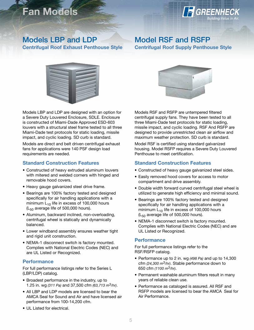
Models LBP and LDP are designed with an option for a Severe Duty Louvered Enclosure, SDLE. Enclosure is constructed of Miami-Dade Approved ESD-603 louvers with a structural steel frame tested to all three Miami-Dade test protocols for static loading, missile impact, and cyclic loading. SD curb is standard.
Models are direct and belt driven centrifugal exhaust fans for applications were 140 PSF design load requirements are needed.
Models RSF and RSFP are untempered filtered centrifugal supply fans. They have been tested to all three Miami-Dade test protocols for static loading, missile impact, and cyclic loading. RSF And RSFP are designed to provide unrestricted clean air airflow and maximum weather protection. SD curb is standard.
Model RSF is certified using standard galvanized housing. Model RSFP requires a Severe Duty Louvered Penthouse to meet certification.
Models LBP and LDPCentrifugal Roof Exhaust Penthouse Style
Model RSF and RSFPCentrifugal Roof Supply Penthouse Style
Standard Construction Features• Constructed of heavy extruded aluminum louvers
with mitered and welded corners with hinged and removable hood covers.
• Heavy gauge galvanized steel drive frame.
• Bearings are 100% factory tested and designed specifically for air handling applications with a minimum L10 life in excess of 100,000 hours (L50 average life of 500,000 hours).
• Aluminum, backward inclined, non-overloading, centrifugal wheel is statically and dynamically balanced.
• Lower windband assembly ensures weather tight and rigid unit construction.
• NEMA-1 disconnect switch is factory mounted. Complies with National Electric Codes (NEC) and are UL Listed or Recognized.
Performance For full performance listings refer to the Series L (LBP/LDP) catalog.
• Broadest performance in the industry, up to 1.25 in. wg (311 Pa) and 37,500 cfm (63,713 m3/hr).
• All LBP and LDP models are licensed to bear the AMCA Seal for Sound and Air and have licensed air performance from 100-14,200 cfm.
• UL Listed for electrical.
Standard Construction Features• Constructed of heavy gauge galvanized steel sides.
• Easily removed hood covers for access to motor compartment and drive assembly.
• Double width forward curved centrifugal steel wheel is utilized to generate high efficiency and minimal sound.
• Bearings are 100% factory tested and designed specifically for air handling applications with a minimum L10 life in excess of 100,000 hours (L50 average life of 500,000 hours).
• NEMA-1 disconnect switch is factory mounted. Complies with National Electric Codes (NEC) and are UL Listed or Recognized.
PerformanceFor full performance listings refer to the RSF/RSFP catalog.
• Performance up to 2 in. wg (498 Pa) and up to 14,300 cfm (24,300 m3/hr). Stable performance down to 650 cfm (1100 m3/hr).
• Permanent washable aluminum filters result in many years of reliable clean use.
• Performance as cataloged is assured. All RSF and RSFP models are licensed to bear the AMCA Seal for Air Performance.
6
Fan Models
6
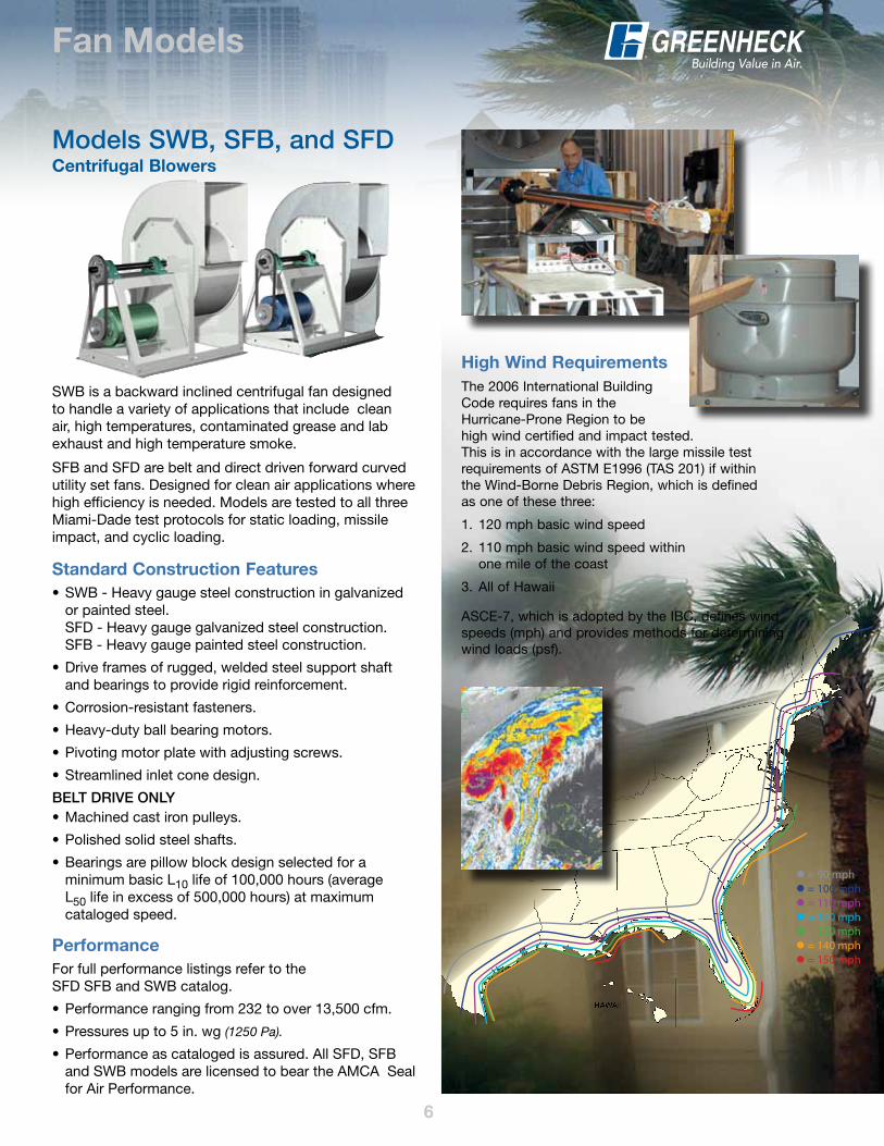
HAWAII
= 90 mph = 100 mph = 110 mph = 120 mph = 130 mph = 140 mph = 150 mph
High Wind RequirementsThe 2006 International Building Code requires fans in the Hurricane-Prone Region to be high wind certified and impact tested. This is in accordance with the large missile test requirements of ASTM E1996 (TAS 201) if within the Wind-Borne Debris Region, which is defined as one of these three:
1. 120 mph basic wind speed
2. 110 mph basic wind speed within one mile of the coast
3. All of Hawaii
ASCE-7, which is adopted by the IBC, defines wind speeds (mph) and provides methods for determining wind loads (psf).
Standard Construction Features• SWB - Heavy gauge steel construction in galvanized
or painted steel.SFD - Heavy gauge galvanized steel construction.SFB - Heavy gauge painted steel construction.
• Drive frames of rugged, welded steel support shaft and bearings to provide rigid reinforcement.
• Corrosion-resistant fasteners.
• Heavy-duty ball bearing motors.
• Pivoting motor plate with adjusting screws.
• Streamlined inlet cone design.
BELT DRIvE onLy• Machined cast iron pulleys.
• Polished solid steel shafts.
• Bearings are pillow block design selected for a minimum basic L10 life of 100,000 hours (average L50 life in excess of 500,000 hours) at maximum cataloged speed.
PerformanceFor full performance listings refer to the SFD SFB and SWB catalog.
• Performance ranging from 232 to over 13,500 cfm.
• Pressures up to 5 in. wg (1250 Pa).
• Performance as cataloged is assured. All SFD, SFB and SWB models are licensed to bear the AMCA Seal for Air Performance.
Models SWB, SFB, and SFDCentrifugal Blowers
SWB is a backward inclined centrifugal fan designed to handle a variety of applications that include clean air, high temperatures, contaminated grease and lab exhaust and high temperature smoke.
SFB and SFD are belt and direct driven forward curved utility set fans. Designed for clean air applications where high efficiency is needed. Models are tested to all three Miami-Dade test protocols for static loading, missile impact, and cyclic loading.
7
Protocol Descriptions
7
TAS-201: Large Missile Impact Test (ASTM E1996)
The Florida Building Code requires that products installed in the Wind-Borne Debris Zone or High-Velocity Hurricane Zone must meet or exceed impact test criteria established under TAS-201. Products may be exempt if utilized in “open” structures or installed more than 30 feet (9 m)above grade. This test procedure measures a product’s capacity to withstand impact from wind-borne debris under hurricane-force wind velocities.
Test Fan Size: Maximum size selected by manufacturer for certification.
Test Missile: 7 foot ( 2.1 m) to 9 foot (2.75 m) long Southern pine 2 x 4; 9.0 to 9.5 pounds.
Distance from Front of Canon to Face of Fan: 9 feet (2.75 m).
Impact Velocity: 50 feet per second (15.25 m/s).
Procedure: Three specimens are tested. One impact is delivered at the center of each specimen and one impact is delivered at top and bottom of each specimen, for a total of three impacts.
Pass/Fail: Failure occurs if a change in the condition of the specimen results…such as “cracking, fastener loosening, local yielding” or if penetration of the projectile occurs beyond the inside plane of the fan.
TAS-202: Uniform Static Air Pressure Test (ASTM E330)
The Florida Building Code requires that all products utilized in structures located throughout the state meet or exceed the structural test criteria established under TAS-202. This test procedure measures a product’s ability to withstand maximum static pressure differentials typical to hurricane events.
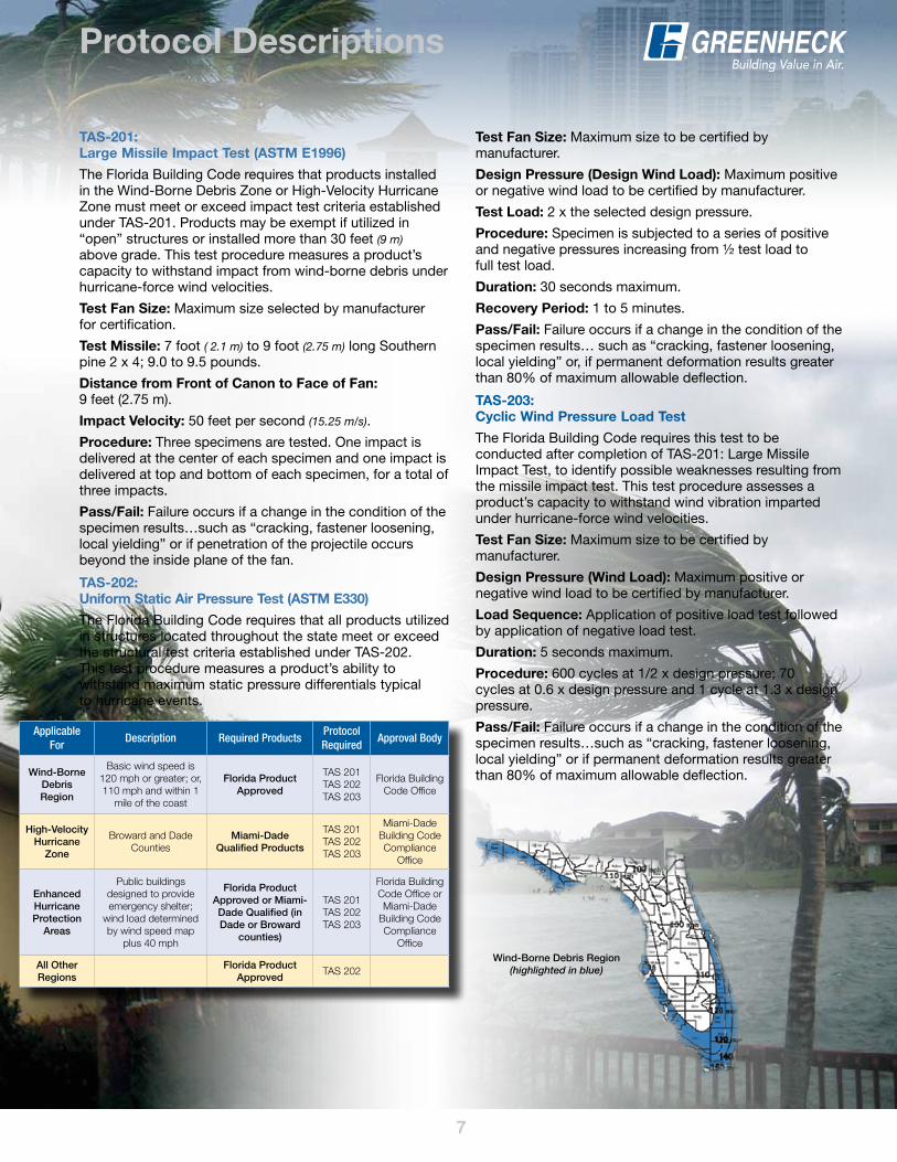
Wind-Borne Debris Region (highlighted in blue)
Test Fan Size: Maximum size to be certified by manufacturer.
Design Pressure (Design Wind Load): Maximum positive or negative wind load to be certified by manufacturer.
Test Load: 2 x the selected design pressure.
Procedure: Specimen is subjected to a series of positive and negative pressures increasing from ½ test load to full test load.
Duration: 30 seconds maximum.
Recovery Period: 1 to 5 minutes.
Pass/Fail: Failure occurs if a change in the condition of the specimen results… such as “cracking, fastener loosening, local yielding” or, if permanent deformation results greater than 80% of maximum allowable deflection.
TAS-203: Cyclic Wind Pressure Load Test
The Florida Building Code requires this test to be conducted after completion of TAS-201: Large Missile Impact Test, to identify possible weaknesses resulting from the missile impact test. This test procedure assesses a product’s capacity to withstand wind vibration imparted under hurricane-force wind velocities.
Test Fan Size: Maximum size to be certified by manufacturer.
Design Pressure (Wind Load): Maximum positive or negative wind load to be certified by manufacturer.
Load Sequence: Application of positive load test followed by application of negative load test.
Duration: 5 seconds maximum.
Procedure: 600 cycles at 1/2 x design pressure; 70 cycles at 0.6 x design pressure and 1 cycle at 1.3 x design pressure.
Pass/Fail: Failure occurs if a change in the condition of the specimen results…such as “cracking, fastener loosening, local yielding” or if permanent deformation results greater than 80% of maximum allowable deflection.
Applicable For
Description Required ProductsProtocol Required
Approval Body
Wind-Borne Debris Region
Basic wind speed is 120 mph or greater; or, 110 mph and within 1
mile of the coast
Florida Product Approved
TAS 201TAS 202TAS 203
Florida Building Code Office
High-velocity Hurricane
Zone
Broward and Dade Counties
Miami-Dade Qualified Products
TAS 201TAS 202TAS 203
Miami-Dade Building Code Compliance
Office
Enhanced Hurricane Protection
Areas
Public buildings designed to provide emergency shelter;
wind load determined by wind speed map
plus 40 mph
Florida Product Approved or Miami-Dade Qualified (in Dade or Broward
counties)
TAS 201TAS 202TAS 203
Florida Building Code Office or Miami-Dade
Building Code Compliance
Office
All other Regions
Florida Product Approved
TAS 202
8
Anchoring
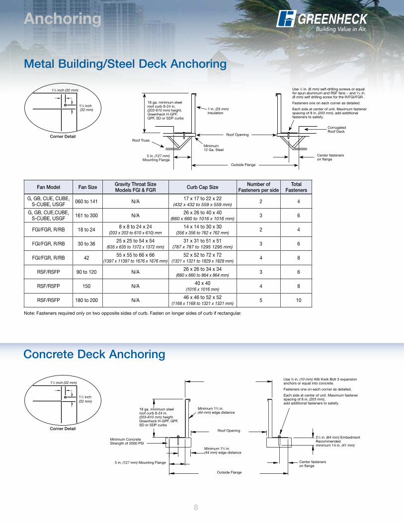
Concrete Deck Anchoring
Corner Detail
CORNER TOP VIEW
Fan Model Fan Size Gravity Throat Size Models FGI & FGR Curb Cap Size number of
Fasteners per sideTotal
Fasteners
G, GB, CUE, CUBE, S-CUBE, USGF 060 to 141 N/A 17 x 17 to 22 x 22
(432 x 432 to 559 x 559 mm)2 4
G, GB, CUE,CUBE, S-CUBE, USGF 161 to 300 N/A 26 x 26 to 40 x 40
(660 x 660 to 1016 x 1016 mm)3 6
FGI/FGR, R/RB 18 to 24 8 x 8 to 24 x 24 (203 x 203 to 610 x 610) mm
14 x 14 to 30 x 30 (356 x 356 to 762 x 762 mm)
2 4
FGI/FGR, R/RB 30 to 36 25 x 25 to 54 x 54 (635 x 635 to 1372 x 1372 mm)
31 x 31 to 51 x 51 (787 x 787 to 1295 1295 mm)
3 6
FGI/FGR, R/RB 42 55 x 55 to 66 x 66 (1397 x 11397 to 1676 x 1676 mm)
52 x 52 to 72 x 72 (1321 x 1321 to 1829 x 1829 mm)
4 8
RSF/RSFP 90 to 120 N/A 26 x 26 to 34 x 34 (660 x 660 to 864 x 864 mm)
3 6
RSF/RSFP 150 N/A 40 x 40 (1016 x 1016 mm)
4 8
RSF/RSFP 180 to 200 N/A 46 x 46 to 52 x 52 (1168 x 1168 to 1321 x 1321 mm)
5 10
Metal Building/Steel Deck Anchoring
Corner Detail
CORNER TOP VIEW
Note: Fasteners required only on two opposite sides of curb. Fasten on longer sides of curb if rectangular.
STEEL DECK ANCHORING DETAIL
Use 1⁄4 in. (6 mm) self-drilling screws or equal for spun aluminum and RSF fans − and 5⁄16 in. (8 mm) self drilling screw for the R/FGI/FGR .
Fasteners one on each corner as detailed.
Each side at center of unit. Maximum fastener spacing of 8 in. (203 mm), add additional fasteners to satisfy.
Center fastenerson flange
Corrugated Roof Deck
1 in. (25 mm) Insulation
Roof Opening
Minimum 12 Ga. Steel
Outside Flange
18 ga. minimum steel roof curb 8-24 in. (203-610 mm) height. Greenheck H-GPF, GPF, SD or SDP curbs
Roof Truss
5 in. (127 mm) Mounting Flange
11⁄4 inch (32 mm)
11⁄4 inch (32 mm)
11⁄4 inch (32 mm)
11⁄4 inch (32 mm)
CONCRETE DECK ANCHORING DETAIL
18 ga. minimum steel roof curb 8-24 in. (203-610 mm) height. Greenheck H-GPF, GPF, SD or SDP curbs
Minimum ConcreteStrength of 2000 PSI
Minimum 13⁄4 in. (44 mm) edge distance
Minimum 13⁄4 in. (44 mm) edge distance
Roof Opening
5 in. (127 mm) Mounting Flange
Outside Flange
Use 3⁄8 in. (10 mm) Hilti Kwik Bolt 3 expansion anchors or equal into concrete.
Fasteners one on each corner as detailed.
Each side at center of unit. Maximum fastener spacing of 8 in. (203 mm), add additional fasteners to satisfy.
21⁄2 in. (64 mm) Embedment Recommended minimum 15⁄8 in. (41 mm)
Center fastenerson flange
Anchoring
Concrete Deck Anchoring
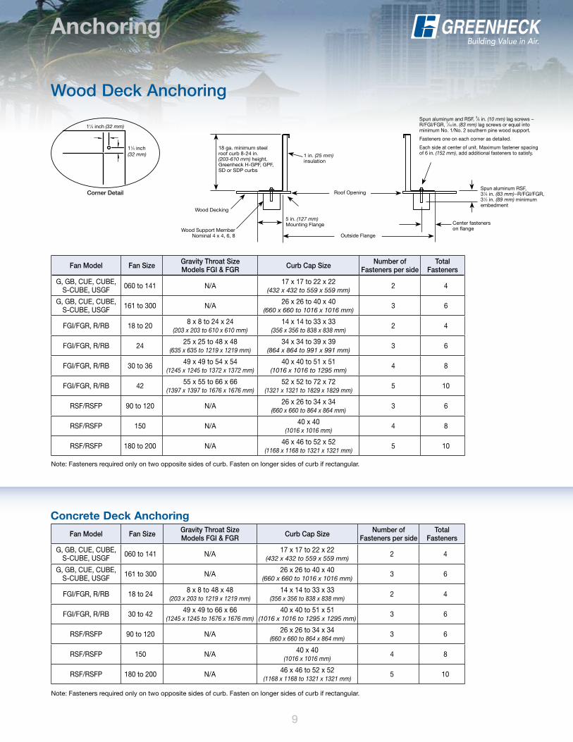
Wood Deck Anchoring
Corner Detail
CORNER TOP VIEW
Fan Model Fan Size Gravity Throat Size Models FGI & FGR Curb Cap Size number of
Fasteners per sideTotal
Fasteners
G, GB, CUE, CUBE, S-CUBE, USGF 060 to 141 N/A 17 x 17 to 22 x 22
(432 x 432 to 559 x 559 mm)2 4
G, GB, CUE, CUBE, S-CUBE, USGF 161 to 300 N/A 26 x 26 to 40 x 40
(660 x 660 to 1016 x 1016 mm)3 6
FGI/FGR, R/RB 18 to 24 8 x 8 to 48 x 48 (203 x 203 to 1219 x 1219 mm)
14 x 14 to 33 x 33 (356 x 356 to 838 x 838 mm)
2 4
FGI/FGR, R/RB 30 to 42 49 x 49 to 66 x 66 (1245 x 1245 to 1676 x 1676 mm)
40 x 40 to 51 x 51 (1016 x 1016 to 1295 x 1295 mm)
3 6
RSF/RSFP 90 to 120 N/A 26 x 26 to 34 x 34 (660 x 660 to 864 x 864 mm)
3 6
RSF/RSFP 150 N/A 40 x 40 (1016 x 1016 mm)
4 8
RSF/RSFP 180 to 200 N/A 46 x 46 to 52 x 52 (1168 x 1168 to 1321 x 1321 mm)
5 10
Fan Model Fan Size Gravity Throat Size Models FGI & FGR Curb Cap Size number of
Fasteners per sideTotal
Fasteners
G, GB, CUE, CUBE, S-CUBE, USGF 060 to 141 N/A 17 x 17 to 22 x 22
(432 x 432 to 559 x 559 mm)2 4
G, GB, CUE, CUBE, S-CUBE, USGF 161 to 300 N/A 26 x 26 to 40 x 40
(660 x 660 to 1016 x 1016 mm)3 6
FGI/FGR, R/RB 18 to 20 8 x 8 to 24 x 24 (203 x 203 to 610 x 610 mm)
14 x 14 to 33 x 33 (356 x 356 to 838 x 838 mm)
2 4
FGI/FGR, R/RB 24 25 x 25 to 48 x 48 (635 x 635 to 1219 x 1219 mm)
34 x 34 to 39 x 39 (864 x 864 to 991 x 991 mm)
3 6
FGI/FGR, R/RB 30 to 36 49 x 49 to 54 x 54 (1245 x 1245 to 1372 x 1372 mm)
40 x 40 to 51 x 51 (1016 x 1016 to 1295 mm)
4 8
FGI/FGR, R/RB 42 55 x 55 to 66 x 66 (1397 x 1397 to 1676 x 1676 mm)
52 x 52 to 72 x 72 (1321 x 1321 to 1829 x 1829 mm)
5 10
RSF/RSFP 90 to 120 N/A 26 x 26 to 34 x 34 (660 x 660 to 864 x 864 mm)
3 6
RSF/RSFP 150 N/A 40 x 40 (1016 x 1016 mm)
4 8
RSF/RSFP 180 to 200 N/A 46 x 46 to 52 x 52 (1168 x 1168 to 1321 x 1321 mm)
5 10
Note: Fasteners required only on two opposite sides of curb. Fasten on longer sides of curb if rectangular.
Note: Fasteners required only on two opposite sides of curb. Fasten on longer sides of curb if rectangular.
9
WOOD DECK ANCHORING DETAIL
Spun aluminum and RSF, 3⁄8 in. (10 mm) lag screws −R/FGI/FGR, 7⁄16 in. (83 mm) lag screws or equal into minimum No. 1/No. 2 southern pine wood support.
Fasteners one on each corner as detailed.
Each side at center of unit. Maximum fastener spacing of 6 in. (152 mm), add additional fasteners to satisfy.
Spun aluminum RSF, 31⁄4 in. (83 mm)−R/FGI/FGR, 31⁄2 in. (89 mm) minimum embedment
Center fastenerson flange
Roof Opening
Outside Flange
5 in. (127 mm) Mounting Flange
1 in. (25 mm) insulation
18 ga. minimum steel roof curb 8-24 in. (203-610 mm) height. Greenheck H-GPF, GPF, SD or SDP curbs
Wood Decking
Wood Support MemberNominal 4 x 4, 6, 8
11⁄4 inch (32 mm)
11⁄4 inch (32 mm)
10
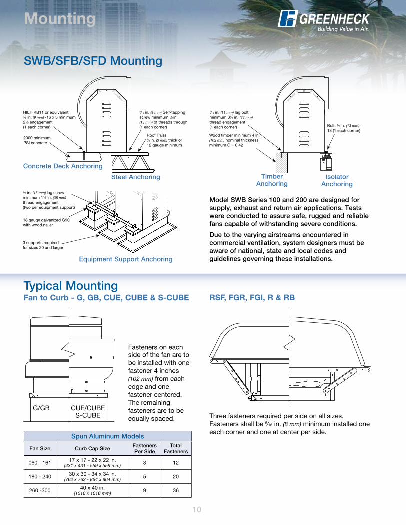
Mounting
Typical Mounting Fan to Curb - G, GB, CUE, CUBE & S-CUBE RSF, FGR, FGI, R & RB
G/GB CUE/CUBE S-CUBE
Fasteners on each side of the fan are to be installed with one fastener 4 inches (102 mm) from each edge and one fastener centered. The remaining fasteners are to be equally spaced. Three fasteners required per side on all sizes.
Fasteners shall be 5⁄16 in. (8 mm) minimum installed one each corner and one at center per side.
SWB/SFB/SFD Mounting
Model SWB Series 100 and 200 are designed for supply, exhaust and return air applications. Tests were conducted to assure safe, rugged and reliable fans capable of withstanding severe conditions.
Due to the varying airstreams encountered in commercial ventilation, system designers must be aware of national, state and local codes and guidelines governing these installations.
Concrete Deck Anchoring
Steel Anchoring
Roof Truss 1⁄8 in. (3 mm) thick or 12 gauge minimum
HILTI KB11 or equivalent3⁄8 in. (9 mm) -16 x 3 minimum 21⁄2 engagement (1 each corner)
5⁄16 in. (8 mm) Self-tapping screw minimum 1⁄2 in. (13 mm) of threads through (1 each corner)
2000 minimum PSI concrete
7⁄16 in. (11 mm) lag bolt minimum 31⁄4 in. (83 mm)thread engagement (1 each corner) Bolt, 1⁄2 in. (13 mm)-
13 (1 each corner)Wood timber minimum 4 in. (102 mm) nominal thickness minimum G = 0.42
Timber Anchoring
Isolator Anchoring
Equipment Support Anchoring
5⁄8 in. (16 mm) lag screw minimum 11⁄2 in. (38 mm) thread engagement (two per equipment support)
3 supports required for sizes 20 and larger
18 gauge galvanized G90 with wood nailer
Spun Aluminum Models
Fan Size Curb Cap Size Fasteners Per Side
Total Fasteners
060 - 161 17 x 17 - 22 x 22 in. (431 x 431 - 559 x 559 mm) 3 12
180 - 240 30 x 30 - 34 x 34 in. (762 x 762 - 864 x 864 mm) 5 20
260 -300 40 x 40 in. (1016 x 1016 mm) 9 36
11
Roof Curbs
Greenheck hurricane and high wind fans are designed for easy mounting to a variety of roof curbs. For your convenience Greenheck offers the industry’s largest selection of tested and approved High Wind and Hurricane roof curbs. Greenheck Models GPF, GPFP, GPFV, SD and SDP curbs offer fully configurable sizes for both flat and pitched roofs. Selectable in sizes up to 80 x 80 inches (2032 x 2032 mm) and heights ranging from 8 inches (203 mm) to 24 inches (610 mm) tall.
For applications where factory supplied curbs are not an option, the Greenheck high wind and hurricane fans can be used in conjunction with any previously installed or customer supplied curbs as long as they meet a series of minimum requirements. Considerations like no wood nailers, minimum material gauges and specific material types may allow field supplied curbs to be acceptable.
GPFThe GPF is a straight sided curb constructed of heavy gauge galvanized steel with a 5-inch (127 mm) flashing flange. It is designed specifically for use in high wind applications on flat roofs. Roofing material can be wrapped up over the top of the curb or can be directly flashed to the side of the curb for a complete tested and certified installation.
GPFPThe GPFP is similar in construction to the GPF. It is constructed of heavy gauge galvanized steel and can be configured to match the pitch of the roof ensuring that any fan mounted to the GPFP is going to sit level and operate properly. The 5-inch (127 mm) flashing flange can be used to secure the curb to the roof of metal (steel), concrete or wood frame building and easily flashed over to ensure weather tightness.
Roof Curbs
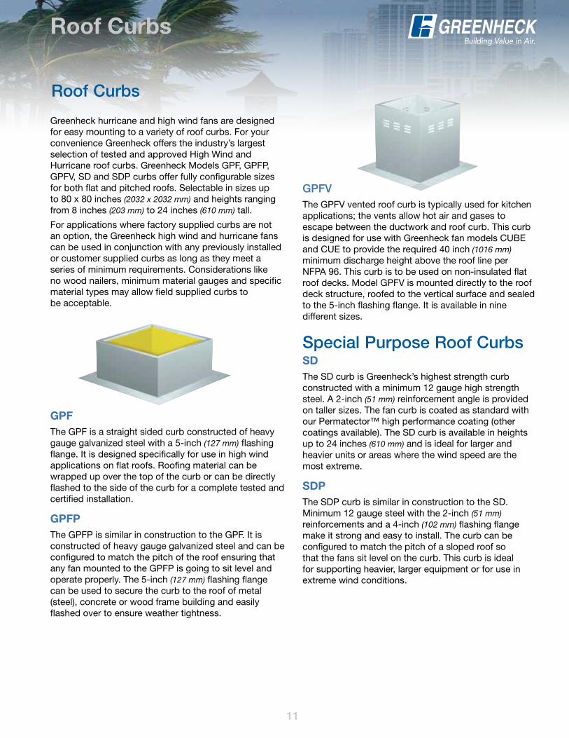
GPFvThe GPFV vented roof curb is typically used for kitchen applications; the vents allow hot air and gases to escape between the ductwork and roof curb. This curb is designed for use with Greenheck fan models CUBE and CUE to provide the required 40 inch (1016 mm) minimum discharge height above the roof line per NFPA 96. This curb is to be used on non-insulated flat roof decks. Model GPFV is mounted directly to the roof deck structure, roofed to the vertical surface and sealed to the 5-inch flashing flange. It is available in nine different sizes.
Special Purpose Roof CurbsSDThe SD curb is Greenheck’s highest strength curb constructed with a minimum 12 gauge high strength steel. A 2-inch (51 mm) reinforcement angle is provided on taller sizes. The fan curb is coated as standard with our Permatector™ high performance coating (other coatings available). The SD curb is available in heights up to 24 inches (610 mm) and is ideal for larger and heavier units or areas where the wind speed are the most extreme.
SDPThe SDP curb is similar in construction to the SD. Minimum 12 gauge steel with the 2-inch (51 mm) reinforcements and a 4-inch (102 mm) flashing flange make it strong and easy to install. The curb can be configured to match the pitch of a sloped roof so that the fans sit level on the curb. This curb is ideal for supporting heavier, larger equipment or for use in extreme wind conditions.

Laboratory Exhaust SystemsEntire Vektor product line
The entire product line of Vektor laboratory exhaust fans are designed to withstand 125 mph windload ratings. No guy wires are needed on these products, allowing complete systems in this line to be installed more efficiently with fewer roof penetrations in the field. For more information on all the benefits of these high wind Vektor products, please refer to any of the Vektor Laboratory Exhaust Systems product catalogs or contact the factory.
LouversFlorida Product Approved and Miami-Dade Qualified
Greenheck offers both Florida Approved and Miami-Dade Qualified Louver products. Models are available that comply with TAS-201 Large Missile Impact Test (ASTM E1996), TAS-203 Cyclic Wind Pressure Load Test, Uniform Static Pressure Test (ASTM E330) and Miami-Dade structural test protocols TAS-201. For specific details on qualifying products refer to Greenheck’s Severe Duty Louvered Products catalog.
Greenheck warrants this equipment to be free from defects in material and workmanship for a period of one
year from the shipment date. Any units or parts which prove defective during the warranty period will be
replaced at our option when returned to our factory, transportation prepaid. Motors are warranted by the motor
manufacturer for a period of one year. Should motors furnished by Greenheck prove defective during this period,
they should be returned to the nearest authorized motor service station. Greenheck will not be responsible for
any removal or installation costs.
As a result of our commitment to continuous improvement, Greenheck reserves the right to change specifications
without notice.
Greenheck P.O. Box 410 • Schofield, WI 54476-0410 • Phone (715) 359-6171 • greenheck.com
Copyright © 2010 Greenheck Fan Corp. • 00.F&V.NB001 R1 3-2010 R
Other Severe Duty Products
Prepared to SupportGreen Building Efforts
our Warranty