Embed Size (px)
Citation preview
Hussong Mfg. Co., Inc. • CSK-335S Report No.: 216-F12c-6.5 • Rev. 02, October 2014
HUSSONG MANUFACTURING CO., INC.
ͷDo not store or use gasoline or other flammable vapors and liquids in the vicinity of this or any other appliance. ͷWHAT TO DO IF YOU SMELL GAS• Do not try to light any appliance.• Do not touch any electrical switch; do
not use any phone in your building.• Leave the building immediately.• Immediately call your gas supplier from
a neighbor’s phone. Follow the gas supplier’s instructions.
• If you cannot reach your gas supplier, call the fire department.
ͷ Installation and service must be performed by a qualified installer, service agency or the gas supplier.
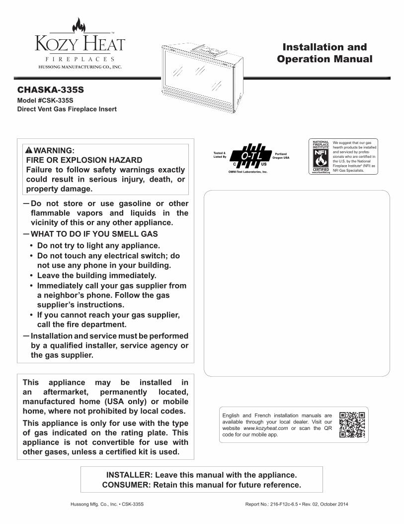
WARNING:FIRE OR EXPLOSION HAZARDFailure to follow safety warnings exactly could result in serious injury, death, or property damage.
This appliance may be installed in an aftermarket, permanently located, manufactured home (USA only) or mobile home, where not prohibited by local codes.This appliance is only for use with the type of gas indicated on the rating plate. This appliance is not convertible for use with other gases, unless a certified kit is used.
INSTALLER: Leave this manual with the appliance. CONSUMER: Retain this manual for future reference.
CHASKA-335SModel #CSK-335SDirect Vent Gas Fireplace Insert
Tested &Listed By O-T L
USC
PortlandOregon USA
OMNI-Test Laboratories, Inc.
Installation and Operation Manual
English and French installation manuals are available through your local dealer. Visit our website www.kozyheat.com or scan the QR code for our mobile app.
1
CONGRATULATIONS! We welcome you as a new owner of a Kozy Heat gas fireplace. Kozy Heat products are designed with superior components and materials; assembled by trained craftsmen who take pride in their work. The burner and valve assembly are 100% test-fired, and the complete fireplace is thoroughly inspected before packaging to ensure you receive a quality product. Our commitment to quality and customer satisfaction has remained the same for over 30 years. We offer a complete line of gas and wood fireplaces, unique cabinets and stylish accessories to complement any décor. Adding a fireplace is one of the best ways to increase the value of your home, and we are proud to offer a network of dealers throughout the country to help make your experience everything you imagine. We pride ourselves in being dedicated not only to functionality and reliability, but also customer safety. We offer our continual support and guidance to help you achieve the maximum benefit and enjoyment from your Kozy Heat gas fireplace.
Read this manual before installing or operating this appliance. Please retain this owner’s manual for future reference.
Dudley Hussong Board Chairman
Jim Hussong President
Homeowner Reference Information
We recommend you record the following information:
Model Name: Date purchased/installed:
Serial Number: Location of fireplace:
Dealership purchased from: Dealer Phone:
Notes:
2
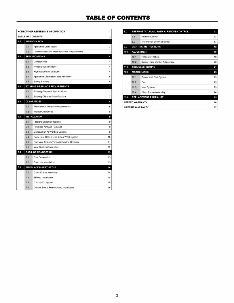
TABLE OF CONTENTS
HOMEOWNER REFERENCE INFORMATION 1
TABLE OF CONTENTS 2
1.0 INTRODUCTION 3
1.1 Appliance Certification 3
1.2 Commonwealth of Massachusetts Requirements 3
2.0 SPECIFICATIONS 4
2.1 Components 4
2.2 Heating Specifications 4
2.3 High Altitude Installations 4
2.4 Appliance Dimensions and Assembly 5
2.5 Safety Barriers 6
3.0 EXISTING FIREPLACE REQUIREMENTS 7
3.1 Existing Fireplace Specifications 7
3.2 Existing Chimney Specifications 7
4.0 CLEARANCES 8
4.1 Placement Clearance Requirements 8
4.2 Mantel Clearances 8
5.0 INSTALLATION 9
5.1 Prepare Existing Fireplace 9
5.2 Fireplace Air Duct Removal 9
5.3 Combustion Air Venting Options 9
5.4 Kozy Heat #816-CL Co-Linear Vent System 10
5.5 Run Vent System Through Existing Chimney 11
5.6 Vent System Connection 12
6.0 GAS LINE CONNECTION 13
6.1 Gas Conversion 13
6.2 Gas Line Installation 13
7.0 FIREPLACE INSERT SETUP 14
7.1 Glass Frame Assembly 14
7.2 Shroud Installation 14
7.3 CXL2-500 Log Set 15
7.4 Control Board Removal and Installation 16
8.0 THERMOSTAT, WALL SWITCH, REMOTE CONTROL 17
8.1 17 Remote Control
8.2 17 Thermostat and Wall Switch
9.0 LIGHTING INSTRUCTIONS 18
10.0 ADJUSTMENT 19
10.1 Pressure Testing 19
10.2 Burner Tube Venturi Adjustment 20
11.0 TROUBLESHOOTING 21
12.0 MAINTENANCE 23
12.1 Burner and Pilot System 23
12.2 Fan 23
12.3 Vent System 23
12.4 Glass Frame Assembly 24
13.0 REPLACEMENT PARTS LIST 25
LIMITED WARRANTY 26
LIFETIME WARRANTY 27
3
This appliance has been tested by OMNI-Test Laboratories located in Portland, Oregon and complies with:
ANSI Z21.88a-2012/CSA 2.33a-2012, “Vented Gas Fireplace Heaters”
CGA 2.17-M91 (R2009), “Gas-Fired Appliances for Use at High Altitudes”
CSA P.4.1-2009, “Testing Method for Measuring Annual Fireplace Efficiency”
This installation must conform with local codes, or in the absence of local codes, with the National Fuel Gas Code, ANSI
Z223.1/NFPA 54, or the Natural Gas and Propane Installation Code, CSA B149.1.
1.0 INTRODUCTION
1.1 Appliance Certification
The following requirements reference various Massachusetts and national codes not contained in this manual.
For all sidewall horizontally vented gas fueled equipment installed in every dwelling, building or structure used in whole or in part for residential purposes, including those owned or operated by the Commonwealth and where the side wall exhaust vent termination is less than (7) feet above finished grade in the area of the venting, including but not limited to decks and porches, the following requirements shall be satisfied:
1.2 Requirements for the Commonwealth of Massachusetts
1.2.1 Installation of Carbon Monoxide Detectors
At time of installation of side wall horizontally vented gas fueled
equipment, the installing plumber or gas-fitter shall observe that a
hard wired carbon monoxide detector with an alarm and battery
back-up is installed on the floor level where the gas equipment is to
be installed. In addition, the installing plumber or gas-fitter shall
observe that a battery operated or hard wired carbon monoxide
detector is installed on each additional level of the dwelling,
building or structure served by the side wall horizontal vented gas
fueled equipment. It shall be the responsibility of the property
owner to secure the services of qualified licensed professionals for
the installation of hard wired carbon monoxide detectors.
In the event that the side wall horizontally vented gas fueled
equipment is installed in a crawl space or attic, the hard wired
carbon monoxide detector with alarm and battery back-up may be
installed on the next adjacent floor level. In the event that the
requirements of this subdivision can not be met at the time of
completion of installation, the owner shall have a period of thirty
(30) days to comply with the above requirements; provided,
however, that during said thirty (30) day period, a battery operated
carbon monoxide detector with an alarm shall be installed.
1.2.2 Approved Carbon Monoxide Detectors
Each carbon monoxide detector as required in accordance with the
above provisions shall comply with NFPA 720 and be ANSI/UL
2034 listed and IAS certified.
1.2.3 Signage
A metal or plastic identification plate shall be permanently mounted
to the exterior of the building at a minimum of eight (8) feet above
grade directly in line with the exhaust vent terminal for the
horizontally vented gas fueled heating appliance or equipment. The
sign shall read, in print no less the one-half inch (1/2) in size, “GAS
VENT DIRECTLY BELOW. KEEP CLEAR OF ALL
OBSTRUCTIONS”.
1.2.4 Inspection
The state or local gas inspector of the side wall horizontally vented
gas fueled equipment shall not approve the installation unless,
upon inspection, the inspector observes carbon monoxide
detectors and signage installed in accordance with the provisions
of 248 CMR 5.08 (2) (a) 1 through 4.
1.2.5 Exemptions
The following equipment is exempt from 248 CMR 5.08 (2) (a) 1
through 4:The equipment listed in Chapter 10 entitled “Equipment
Not Required To Be Vented” in the most current edition of NFPA 54
as adopted by the Board; and Product Approved side wall
horizontally vented gas fueled equipment installed in a room or
structure separate from the dwelling, building or structure used in
whole or in part for residential purposes.
1.2.6 Manufacturer Requirements
1.2.6.1 Gas Equipment Venting System Provided
When the manufacturer of Product Approved side wall horizontally
vented gas equipment provides a venting system design or venting
system components with the equipment, the instructions provided
by the manufacturer for installation of the equipment and the
venting system shall include:
Detailed instructions for the installation of the venting system
design or the venting system components; and
A complete parts list for the venting system design or venting
system.
1.2.6.1 Gas Equipment Venting System NOT Provided
When the manufacturer of Product Approved side wall horizontally
vented gas equipment does not provide the parts for venting the
flue gases, but identifies “special venting systems”, the following
requirements shall be satisfied by the manufacturer:
The referenced “special venting systems” instructions shall be
included with the appliance or equipment installation instructions
and;
The “special venting systems” shall be Product Approved by the
Board, and the instructions for that system shall include a parts
list and detailed installation instructions.
A copy of all installation instructions for all Product Approved side
wall horizontally vented gas fueled equipment, all venting
instructions, all parts lists for venting instructions, and/or all venting
design instructions shall remain with the appliance or equipment at
the completion of the installation.
4
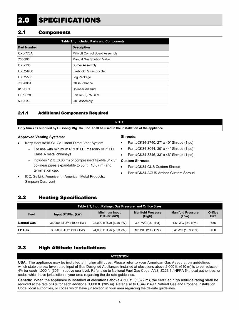
Table 2.1, Included Parts and Components
Part Number Description
CXL-770A Millivolt Control Board Assembly
700-203 Manual Gas Shut-off Valve
CXL-135 Burner Assembly
CXL2-I900 Firebrick Refractory Set
CXL2-500 Log Package
700-006T Glass Valance
816-CL1 Colinear Air Duct
CSK-028 Fan Kit (2)-75 CFM
500-CXL Grill Assembly
2.0 SPECIFICATIONS
2.2 Heating Specifications
Table 2.3, Input Ratings, Gas Pressure, and Orifice Sizes
Fuel Input BTU/hr. (kW) Minimum Input BTU/hr. (kW)
Orifice Size
Manifold Pressure (Low)
Manifold Pressure (High)
Natural Gas 36,000 BTU/h (10.55 kW) 22,000 BTU/h (6.49 kW) #35 1.6” WC (.40 kPa) 3.5” WC (.87 kPa)
LP Gas 36,500 BTU/h (10.7 kW) 24,000 BTU/h (7.03 kW) #50 6.4” WC (1.59 kPa) 10” WC (2.49 kPa)
2.3 High Altitude Installations
ATTENTION
USA: The appliance may be installed at higher altitudes. Please refer to your American Gas Association guidelines which state the sea level rated input of Gas Designed Appliances installed at elevations above 2,000 ft. (610 m) is to be reduced 4% for each 1,000 ft. (305 m) above sea level. Refer also to National Fuel Gas Code, ANSI Z223.1 / NFPA 54, local authorities, or codes which have jurisdiction in your area regarding the de-rate guidelines.
Canada: When the appliance is installed at elevations above 4,500 ft. (1,372 m), the certified high altitude rating shall be reduced at the rate of 4% for each additional 1,000 ft. (305 m). Refer also to CSA-B149.1 Natural Gas and Propane Installation Code, local authorities, or codes which have jurisdiction in your area regarding the de-rate guidelines.
2.1 Components
2.1.1 Additional Components Required
Approved Venting Systems:
Kozy Heat #816-CL Co-Linear Direct Vent System
For use with minimum 6” x 8” I.D. masonry or 7” I.D.
Class A metal chimneys
Includes 12 ft. (3.66 m) of compressed flexible 3” x 3”
co-linear pipes expandable to 35 ft. (10.67 m) and
termination cap.
ICC, Selkirk, Amerivent - American Metal Products,
Simpson Dura-vent
Shrouds:
Part #CK34-2740, 27” x 40” Shroud (1 pc)
Part #CK34-3044, 30” x 44” Shroud (1 pc)
Part #CK34-3346, 33” x 46” Shroud (1 pc)
Custom Shrouds:
Part #CK34-CUS Custom Shroud
Part #CK34-ACUS Arched Custom Shroud
NOTE
Only trim kits supplied by Hussong Mfg. Co., Inc. shall be used in the installation of the appliance.

5
Table 2.4, Physical Dimensions
Description Height Width Back Width Depth Back Height Back to Gas Line
Access Front to Vent
Center Back to Vent
Center Back to Electrical
Access
Inches 23 33-3/8 24-3/8 16 17-1/4 5-1/8 11 5 9-1/2
Millimeters 876 1038 743 406 438 130 279 127 241
2.4 Appliance Dimensions and Assembly
TOP
FRONT RIGHTLEFT
2438"
619mm
32"
813mm
1818"
460mm23"
584mm
3338"
848mm
11"
279mm
5"
127mm
16"
406mm
1714"
438mm
518"
130mm
912"
241mm
178"
48mm
TOP
FRONT RIGHTLEFT
2438"
619mm
32"
813mm
1818"
460mm23"
584mm
3338"
848mm
11"
279mm
5"
127mm
16"
406mm
1714"
438mm
518"
130mm
912"
241mm
178"
48mm
TOP
FRONT RIGHTLEFT
2438"
619mm
32"
813mm
1818"
460mm23"
584mm
3338"
848mm
11"
279mm
5"
127mm
16"
406mm
1714"
438mm
518"
130mm
912"
241mm
178"
48mm
TOP
FRONT RIGHTLEFT
2438"
619mm
32"
813mm
1818"
460mm23"
584mm
3338"
848mm
11"
279mm
5"
127mm
16"
406mm
1714"
438mm
518"
130mm
912"
241mm
178"
48mm
Figure 2.1, CSK-335S Dimensions
Table 2.5, CSK-335S Part Assembly Overview
A Fireplace insert
B Spring-loaded latch glass assembly
C Control board with burner cover
D Co-linear air duct
E Log set
F Refractory panels
G Fan kit (Not shown)
WARNING
Failure to position these components in accordance with these diagrams, or failure to use only parts specifically approved with this appliance, may result in property damage or personal injury.
B
C
F
A
D
Figure 2.2, CSK-335S Exploded View
6
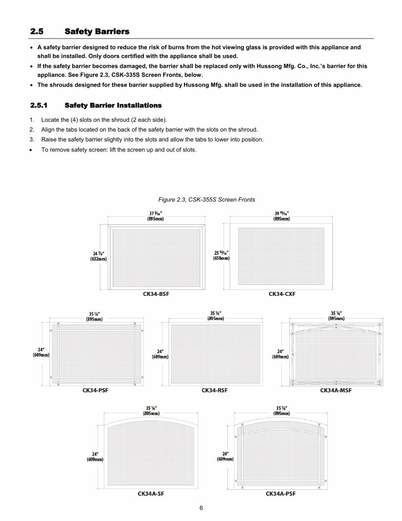
A safety barrier designed to reduce the risk of burns from the hot viewing glass is provided with this appliance and
shall be installed. Only doors certified with the appliance shall be used.
If the safety barrier becomes damaged, the barrier shall be replaced only with Hussong Mfg. Co., Inc.’s barrier for this
appliance. See Figure 2.3, CSK-335S Screen Fronts, below.
The shrouds designed for these barrier supplied by Hussong Mfg. shall be used in the installation of this appliance.
Figure 2.3, CSK-355S Screen Fronts
2.5 Safety Barriers
2.5.1 Safety Barrier Installations
1. Locate the (4) slots on the shroud (2 each side).
2. Align the tabs located on the back of the safety barrier with the slots on the shroud.
3. Raise the safety barrier slightly into the slots and allow the tabs to lower into position.
To remove safety screen: lift the screen up and out of slots.
7
This fireplace insert is to be installed into a solid fuel masonry or factory built non-combustible fireplace that has been installed
in accordance with the national, provincial, state, and local building codes.
The existing fireplace and chimney must be clean, in good working order, and be constructed of non-combustible materials.
Any smoke shelves, shields, and baffles may be removed if attached by mechanical fasteners. If necessary, remove firebrick to
obtain at least the minimum opening requirements.
A gas line must be able to be installed to the insert. Refer to 6.0, Gas Line Connection, on page 13.
Provisions must be made to provide electrical power for appliance operation.
Adequate accessibility clearances for servicing and proper operation must be maintained.
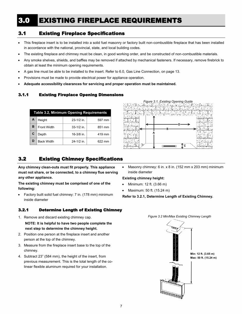
3.1.1 Existing Fireplace Opening Dimensions
3.0 EXISTING FIREPLACE REQUIREMENTS
3.1 Existing Fireplace Specifications
Any chimney clean-outs must fit properly. This appliance
must not share, or be connected, to a chimney flue serving
any other appliance.
The existing chimney must be comprised of one of the
following:
Factory built solid fuel chimney: 7 in. (178 mm) minimum
inside diameter
Masonry chimney: 6 in. x 8 in. (152 mm x 203 mm) minimum
inside diameter
Existing chimney height:
Minimum: 12 ft. (3.66 m)
Maximum: 50 ft. (15.24 m)
Refer to 3.2.1, Determine Length of Existing Chimney.
3.2.1 Determine Length of Existing Chimney
1. Remove and discard existing chimney cap.
NOTE: It is helpful to have two people complete the
next step to determine the chimney height.
2. Position one person at the fireplace insert and another
person at the top of the chimney.
3. Measure from the fireplace insert base to the top of the
chimney.
4. Subtract 23” (584 mm), the height of the insert, from
previous measurement. This is the total length of the co-
linear flexible aluminum required for your installation.
3.2 Existing Chimney Specifications
Table 3.2, Minimum Opening Requirements
A Height 23-1/2 in. 597 mm
B Front Width 33-1/2 in. 851 mm
C Depth 16-3/8 in. 419 mm
D Back Width 24-1/2 in. 622 mm
Figure 3.1, Existing Opening Guide
A
B
D
C
Min: 12 ft. (3.65 m)
Max: 50 ft. (15.24 m)
Figure 3.2 Min/Max Existing Chimney Length
8
4.1 Fireplace Insert Placement Considerations
This fireplace must be installed on a level surface capable of supporting the fireplace insert and venting.
Due to high surface temperatures, the fireplace insert should be located out of traffic and away from furniture and draperies.
This fireplace insert may be installed in a bedroom.
Please be aware of the large amount of heat this fireplace insert will produce when determining a location.
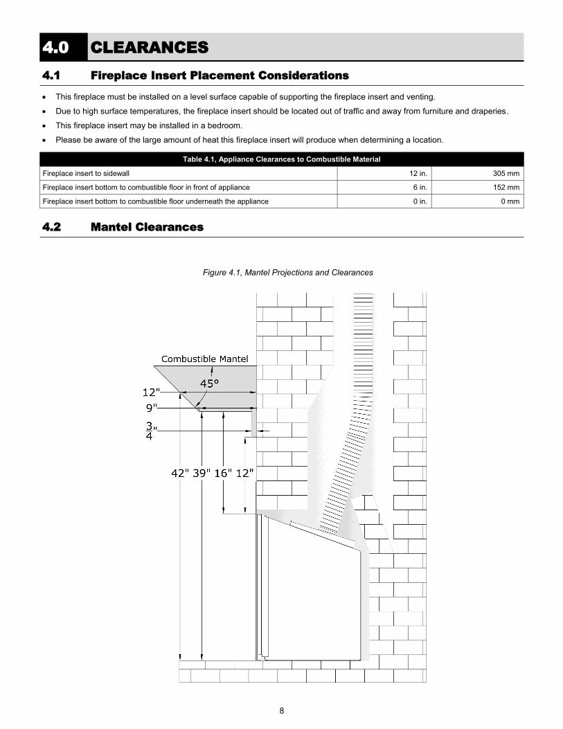
Table 4.1, Appliance Clearances to Combustible Material
Fireplace insert to sidewall 12 in. 305 mm
Fireplace insert bottom to combustible floor in front of appliance 6 in. 152 mm
Fireplace insert bottom to combustible floor underneath the appliance 0 in. 0 mm
4.0 CLEARANCES
4.2 Mantel Clearances
Figure 4.1, Mantel Projections and Clearances
9
5.0 INSTALLATION
5.1 Prepare Existing Fireplace
CAUTION
Trim panels or surrounds must not seal ventilation openings in existing fireplace that this appliance is installed in.
The refractory, glass doors, screen rails, screen mesh, and log grates may be removed from existing fireplace before installing
this gas fireplace insert.
The fireplace flue damper can be fully blocked, open, or removed for installation of this gas fireplace insert.
Clean the chimney and inside of the fireplace to prevent a creosote smell from entering the home.
Cutting of any sheet metal parts of the existing fireplace is prohibited, except the metal floor.
If the metal floor is removed, the insert must be placed directly on metal base of metal fireplace. Mechanically attach ‘THIS
UNIT HAS BEEN MODIFIED’ label at bottom of existing firebox so it will be visible if this gas fireplace insert is removed.
If the factory-built fireplace has no gas access hole(s) provided, an access hole of 1-1/2 in. (37.5 mm) or less may be drilled
through the lower sides or bottom of the firebox in a proper workmanship like manner. The access hole must be plugged with
non-combustible insulation after the gas supply line has been installed.
Run any necessary electrical wiring to insert.
ATTENTION
Any removed parts must be capable of reinstallation if this insert is ever removed. Removal of rivets or screws is acceptable.
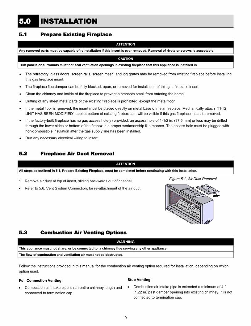
1. Remove air duct at top of insert, sliding backwards out of channel.
Refer to 5.6, Vent System Connection, for re-attachment of the air duct.
ATTENTION
All steps as outlined in 5.1, Prepare Existing Fireplace, must be completed before continuing with this installation.
Figure 5.1, Air Duct Removal
5.2 Fireplace Air Duct Removal
5.3 Combustion Air Venting Options
Full Connection Venting:
Combustion air intake pipe is ran entire chimney length and
connected to termination cap.
Stub Venting:
Combustion air intake pipe is extended a minimum of 4 ft.
(1.22 m) past damper opening into existing chimney. It is not
connected to termination cap.
Follow the instructions provided in this manual for the combustion air venting option required for installation, depending on which
option used.
WARNING
This appliance must not share, or be connected to, a chimney flue serving any other appliance.
The flow of combustion and ventilation air must not be obstructed.
10
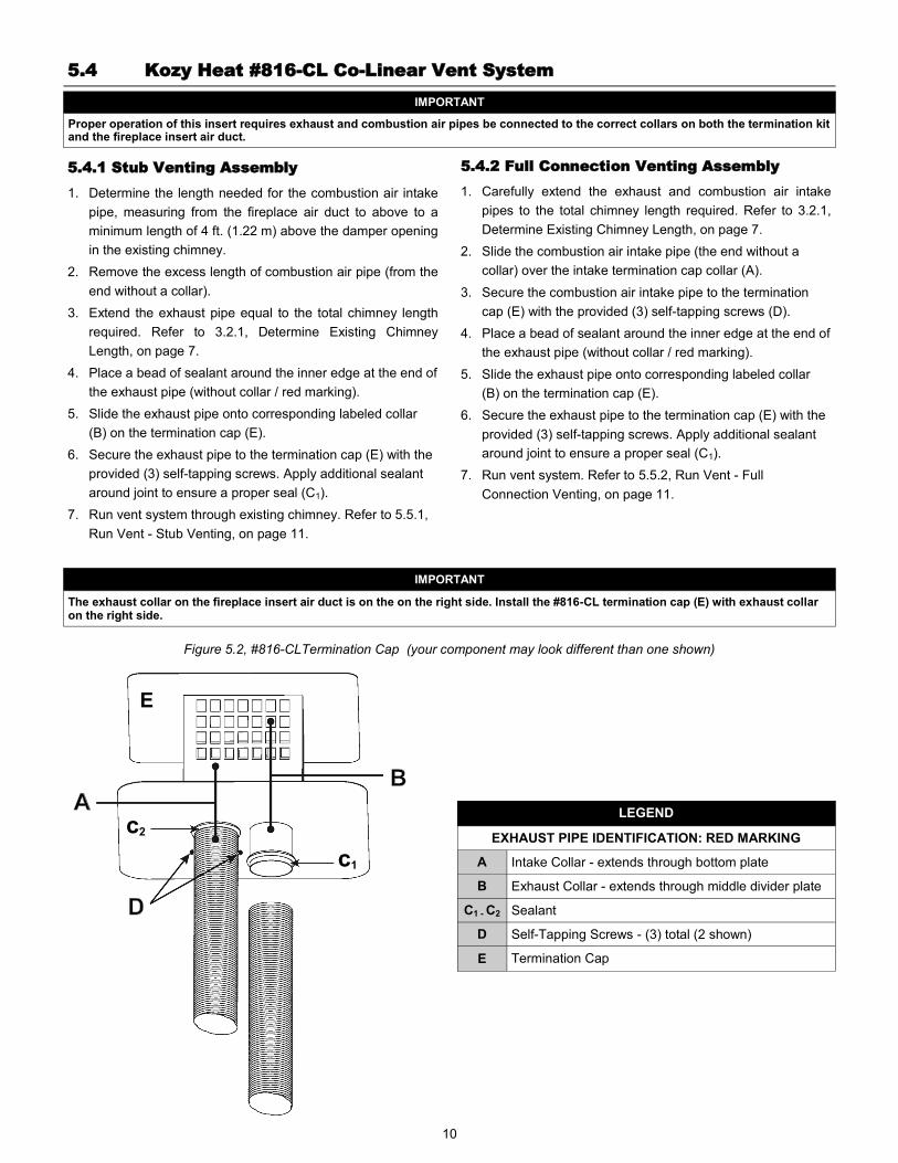
LEGEND
EXHAUST PIPE IDENTIFICATION: RED MARKING
A Intake Collar - extends through bottom plate
B Exhaust Collar - extends through middle divider plate
C1 - C2 Sealant
D Self-Tapping Screws - (3) total (2 shown)
E Termination Cap
Figure 5.2, #816-CLTermination Cap (your component may look different than one shown)
5.4.1 Stub Venting Assembly
1. Determine the length needed for the combustion air intake
pipe, measuring from the fireplace air duct to above to a
minimum length of 4 ft. (1.22 m) above the damper opening
in the existing chimney.
2. Remove the excess length of combustion air pipe (from the
end without a collar).
3. Extend the exhaust pipe equal to the total chimney length
required. Refer to 3.2.1, Determine Existing Chimney
Length, on page 7.
4. Place a bead of sealant around the inner edge at the end of
the exhaust pipe (without collar / red marking).
5. Slide the exhaust pipe onto corresponding labeled collar
(B) on the termination cap (E).
6. Secure the exhaust pipe to the termination cap (E) with the
provided (3) self-tapping screws. Apply additional sealant
around joint to ensure a proper seal (C1).
7. Run vent system through existing chimney. Refer to 5.5.1,
Run Vent - Stub Venting, on page 11.
5.4.2 Full Connection Venting Assembly
1. Carefully extend the exhaust and combustion air intake
pipes to the total chimney length required. Refer to 3.2.1,
Determine Existing Chimney Length, on page 7.
2. Slide the combustion air intake pipe (the end without a
collar) over the intake termination cap collar (A).
3. Secure the combustion air intake pipe to the termination
cap (E) with the provided (3) self-tapping screws (D).
4. Place a bead of sealant around the inner edge at the end of
the exhaust pipe (without collar / red marking).
5. Slide the exhaust pipe onto corresponding labeled collar
(B) on the termination cap (E).
6. Secure the exhaust pipe to the termination cap (E) with the
provided (3) self-tapping screws. Apply additional sealant
around joint to ensure a proper seal (C1).
7. Run vent system. Refer to 5.5.2, Run Vent - Full
Connection Venting, on page 11.
IMPORTANT
Proper operation of this insert requires exhaust and combustion air pipes be connected to the correct collars on both the termination kit and the fireplace insert air duct.
5.4 Kozy Heat #816-CL Co-Linear Vent System
IMPORTANT
The exhaust collar on the fireplace insert air duct is on the on the right side. Install the #816-CL termination cap (E) with exhaust collar on the right side.
E
c2
c1

11
5.5.1 Run Vent - Stub Venting
1. Guide the rope (if used) and the exhaust pipe down the
existing chimney. See Figure 5.3, Chimney Vent Run.
2. Secure the chimney termination cap to the existing
chimney.
Approved Vent Systems: Apply a liberal bead of
sealant (provided) around the top of existing chimney. Set
termination cap into position as instructed in installation
manual included with chosen vent system.
Kozy Heat #816-CL: Secure termination cap to
existing chimney with 2 in. (50 mm) self tapping screws
and anchor straps (provided) through the pilot holes,
located on the sides of the termination cap.
3. From inside the existing fireplace, insert a minimum of 4 ft.
(1.22m) of combustion air pipe (end without collar) past the
damper opening and into the existing fireplace firebox. See
Figure 5.4, Stub Venting.
Hussong Mfg. strongly suggests placing non-faced
fiberglass insulation between the vent pipes and the
existing chimney to prevent heat loss up the chimney,
being careful not to the block the combustion air intake
pipe end.
5.5.2 Run Vent - Full Connection Venting
Hussong Mfg. strongly suggests wrapping first 3 ft. (914
mm) of vent system below termination cap with non-faced
fiberglass insulation (secure with wire) before running it
through existing chimney. This will prevent cold air from
coming down existing chimney.
1. Guide ropes (if used) and the flexible pipes down the
existing chimney. See Figure 5.3, Chimney Vent Run.
2. Secure the chimney termination cap to the existing
chimney.
Approved Vent Systems: Apply a liberal bead of
sealant (provided) around top of existing chimney. Set
termination cap into position as instructed in installation
manual included with chosen vent system.
Kozy Heat #816-CL: Secure termination cap to
existing chimney with 2 in. (50 mm) self tapping screws
and anchor straps (provided) through the pilot holes,
located on the sides of the termination cap.
3. From inside the existing fireplace, carefully pull ropes (if
used) or the flexible pipes down until both the exhaust pipe
and the combustion air intake are into the existing fireplace
firebox.
NOTE
If offsets are present in existing chimney, place a weighted rope around the pipe ends to guide them through chimney. DO NOT ATTEMPT TO TIE ONE ROPE AROUND BOTH PIPES.
Minimum 4 ft. (1.22m) length of 3” (76 mm) combustion air flex pipe above register opening
DO NOT block pipe end with insulation or any other sealing materials
3" (76 mm) exhaust flex pipe must be connected to collar on fireplace insert and termination cap
Seal area around vent pipes with non-faced fiberglass insulation
Figure 5.4, Stub Venting Figure 5.3, Chimney Vent Run
5.5 Run Vent System Through Existing Chimney
12
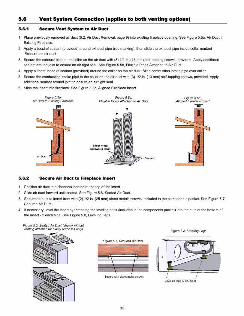
1. Place previously removed air duct (5.2, Air Duct Removal, page 9) into existing fireplace opening. See Figure 5.5a, Air Duct in
Existing Fireplace.
2. Apply a bead of sealant (provided) around exhaust pipe (red marking), then slide the exhaust pipe inside collar marked
‘Exhaust’ on air duct.
3. Secure the exhaust pipe to the collar on the air duct with (3) 1/2 in. (13 mm) self-tapping screws, provided. Apply additional
sealant around joint to ensure an air tight seal. See Figure 5.5b, Flexible Pipes Attached to Air Duct.
4. Apply a liberal bead of sealant (provided) around the collar on the air duct. Slide combustion intake pipe over collar.
5. Secure the combustion intake pipe to the collar on the air duct with (3) 1/2 in. (13 mm) self-tapping screws, provided. Apply
additional sealant around joint to ensure an air tight seal.
6. Slide the insert into fireplace. See Figure 5.5c, Aligned Fireplace Insert.
1. Position air duct into channels located at the top of the insert.
2. Slide air duct forward until seated. See Figure 5.6, Seated Air Duct.
3. Secure air duct to insert front with (2) 1/2 in. (25 mm) sheet metals screws, included in the components packet. See Figure 5.7,
Secured Air Duct.
4. If necessary, level the insert by threading the leveling bolts (included in the components packet) into the nuts at the bottom of
the insert - 2 each side. See Figure 5.8, Leveling Legs.
5.6.2 Secure Air Duct to Fireplace Insert
Figure 5.5c, Aligned Fireplace Insert
Figure 5.5a, Air Duct in Existing Fireplace
Air Duct
5.6 Vent System Connection (applies to both venting options)
5.6.1 Secure Vent System to Air Duct
Figure 5.5b, Flexible Pipes Attached to Air Duct
Sealant
Sheet metal screws (3 total)
Figure 5.6, Seated Air Duct (shown without venting attached for clarity purposes only)
Secure with sheet metal screws
Figure 5.7, Secured Air Duct
Leveling legs (2 ea. side)
Figure 5.8, Leveling Legs

13
Table 6.1, Inlet Gas Pressures
Fuel Minimum Pressure Maximum Pressure
Natural Gas 5” WC (1.25 kPa) 10.5” WC (2.62 kPa)
LP Gas 11” WC (2.74 kPa) 13” WC (3.24 kPa)
6.0 GAS LINE CONNECTION
6.2 Gas Line Installation
6.1 Gas Conversion (sold separately)
This fireplace is manufactured for use with Natural Gas. Follow the instructions included with the conversion kit if converting to
LP gas.
ATTENTION
The conversion shall be carried out in accordance with the requirements of the provincial authorities having jurisdiction and in accordance with the requirements of the ANSI Z223.1 installation code.
CAUTION
Installation of the gas line must only be done by a qualified person in accordance with local building codes, if any. If not, follow ANSI
223.1. Commonwealth of Massachusetts installations must be done by a licensed plumber or gas fitter.
A listed (and Commonwealth of Massachusetts approved) 1/2 in. (13 mm) tee handle manual shut-off valve and flexible gas
connector are to be connected to the 1/2 in. (13 mm) control valve inlet. If substituting for these components, please consult
local codes for compliance.
If installing this insert into minimum opening dimensions, the gas line may need to be run after placement due to space
limitations. Refer to 3.1.1, Existing Fireplace Opening Specifications, on page 7.
This fireplace is equipped with a 3/8” (10 mm) x 18” (457 mm) long flexible gas connector and manual shut-off valve.
Run gas line into fireplace, preferably through left or right gas line holes provided. The gas line should be run to the point of
connection where the shut-off valve and flexible gas line will connect.
Do not run gas line in a manner that would obstruct fan operation.
For high altitude installations, consult the local gas distributor or the authority having jurisdiction for proper rating methods.
NOTE
The appliance and its individual shutoff valve must be disconnected from the gas supply piping system during any pressure testing of
that system at pressures in excess of ½ psi (3.5 kPa). For test pressures equal to or less than ½ psi (3.5 kPa), the appliance must be
isolated from the gas supply piping system by closing its individual manual shut-off valve.
Leak test all gas line joints and the gas control valve prior to lighting the appliance.

14
7.0 FIREPLACE INSERT SETUP
WARNING
Do not operate this fireplace with the glass removed, cracked, or broken. Replacement of the glass frame assembly, #700-006T, should be done by a licensed or qualified service person.
Do not remove the glass frame assembly when hot.
1. Align the slots on top of the glass frame assembly over the
tabs at the top of the firebox while lowering the bottom of
the glass frame assembly into position. Refer to Figure 7.1,
Glass Frame Assembly Removal and Installation.
2. Pull the spring-loaded latches out and up to secure the
bottom of glass frame to the bottom of the fireplace.
1. Locate (2) spring-loaded latches securing the glass frame
assembly at the bottom of the firebox. Refer to Figure 7.1,
Glass Frame Assembly Removal and Installation.
2. Pull the spring-loaded latches out and down to release the
bottom of the glass frame assembly.
3. Lift glass frame assembly up and off of the (2) tabs located
at the top of the firebox.
Figure 7.1, Glass Frame Assembly Removal and Installation
7.1 Glass Frame Assembly
7.1.1 Remove Glass Frame Assembly
7.1.2 Install Glass Frame Assembly
7.2 Shroud Installation
For shrouds #CK34-2740, #CK34-3044, #CK34-3346, #CK34-
A344, #CK34-CUS, and #CK34-ACUS.
1. Remove the upper hood by lifting up and out of the
mounting flanges.
2. Remove lower louver by lifting the louver out of the slots on
the mounting flanges.
3. Remove the glass assembly.
4. Align the mounting holes on the shroud to the
corresponding mounting nuts on the sides of the insert
metal cabinet.
5. Secure with (4) truss head screws (provided).
6. Reinstall all components previously removed.
Figure 7.2, Upper Hood and Lower Louver Figure 7.3, Mounting Nut Locations
MOUNTING NUTS (2 EACH SIDE)
15
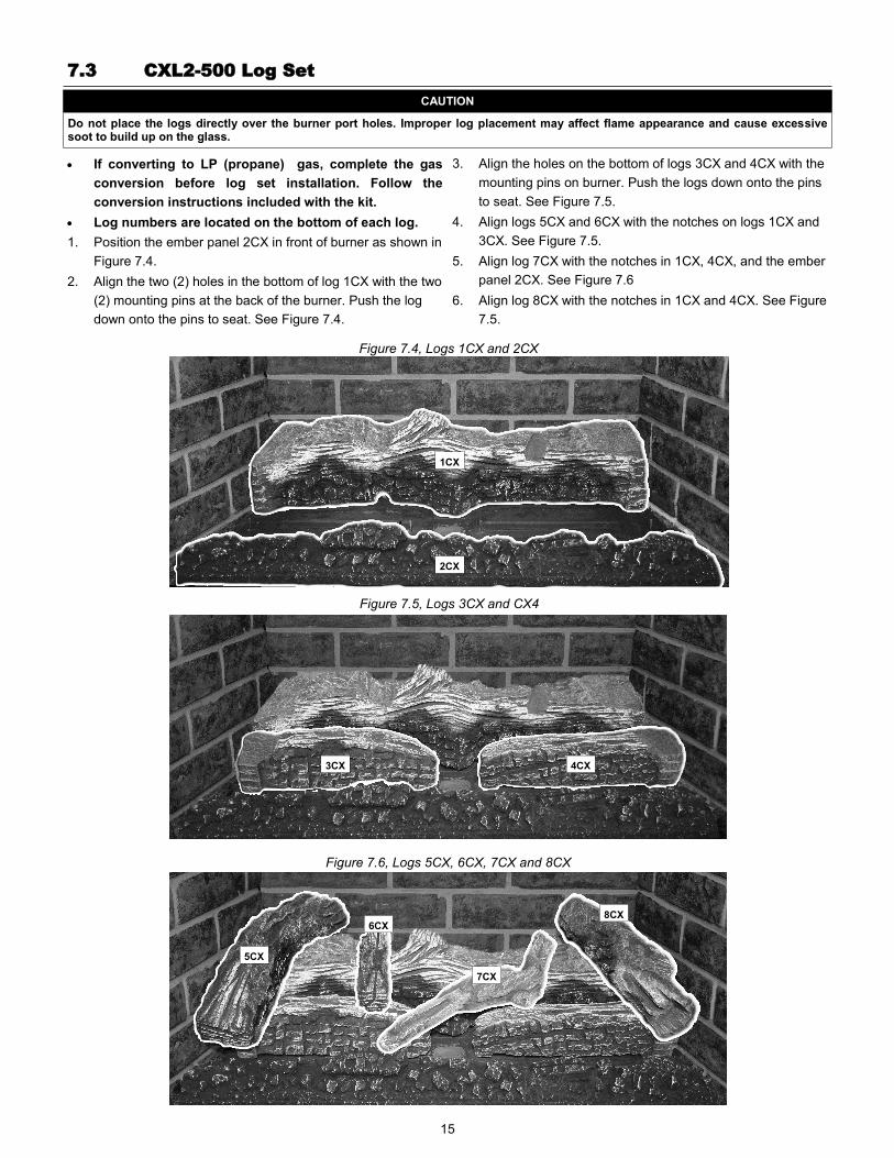
7.3 CXL2-500 Log Set
CAUTION
Do not place the logs directly over the burner port holes. Improper log placement may affect flame appearance and cause excessive soot to build up on the glass.
If converting to LP (propane) gas, complete the gas
conversion before log set installation. Follow the
conversion instructions included with the kit.
Log numbers are located on the bottom of each log.
1. Position the ember panel 2CX in front of burner as shown in
Figure 7.4.
2. Align the two (2) holes in the bottom of log 1CX with the two
(2) mounting pins at the back of the burner. Push the log
down onto the pins to seat. See Figure 7.4.
3. Align the holes on the bottom of logs 3CX and 4CX with the
mounting pins on burner. Push the logs down onto the pins
to seat. See Figure 7.5.
4. Align logs 5CX and 6CX with the notches on logs 1CX and
3CX. See Figure 7.5.
5. Align log 7CX with the notches in 1CX, 4CX, and the ember
panel 2CX. See Figure 7.6
6. Align log 8CX with the notches in 1CX and 4CX. See Figure
7.5.
Figure 7.4, Logs 1CX and 2CX
1CX
2CX
Figure 7.5, Logs 3CX and CX4
3CX 4CX
Figure 7.6, Logs 5CX, 6CX, 7CX and 8CX
8CX
7CX
6CX
5CX
16
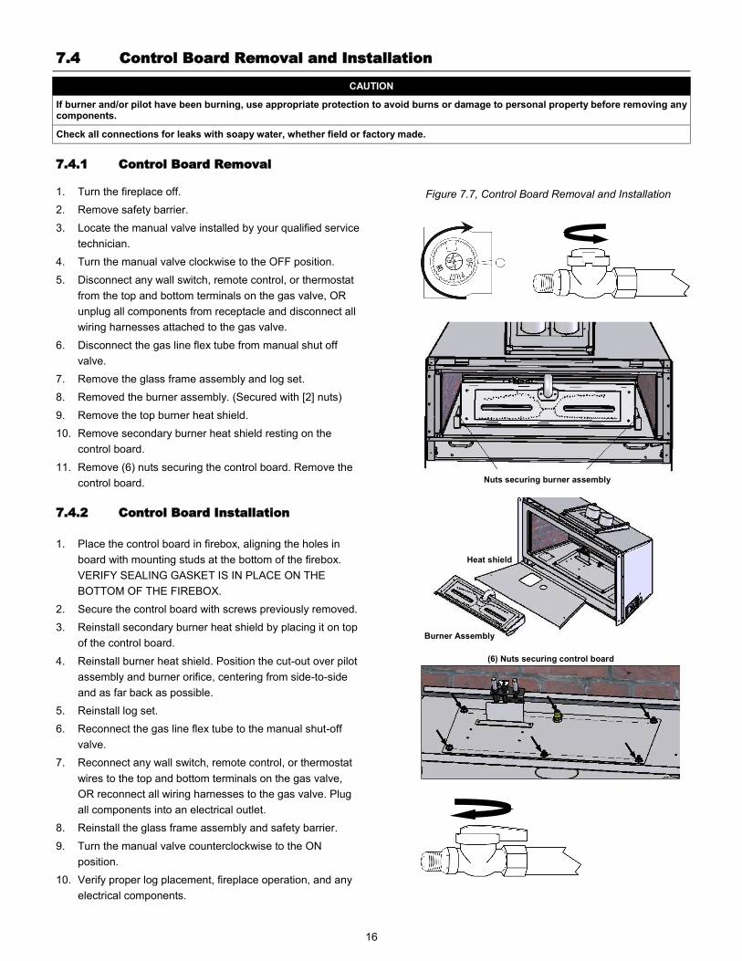
7.4 Control Board Removal and Installation
Heat shield
Burner Assembly
Nuts securing burner assembly
1. Turn the fireplace off.
2. Remove safety barrier.
3. Locate the manual valve installed by your qualified service
technician.
4. Turn the manual valve clockwise to the OFF position.
5. Disconnect any wall switch, remote control, or thermostat
from the top and bottom terminals on the gas valve, OR
unplug all components from receptacle and disconnect all
wiring harnesses attached to the gas valve.
6. Disconnect the gas line flex tube from manual shut off
valve.
7. Remove the glass frame assembly and log set.
8. Removed the burner assembly. (Secured with [2] nuts)
9. Remove the top burner heat shield.
10. Remove secondary burner heat shield resting on the
control board.
11. Remove (6) nuts securing the control board. Remove the
control board.
1. Place the control board in firebox, aligning the holes in
board with mounting studs at the bottom of the firebox.
VERIFY SEALING GASKET IS IN PLACE ON THE
BOTTOM OF THE FIREBOX.
2. Secure the control board with screws previously removed.
3. Reinstall secondary burner heat shield by placing it on top
of the control board.
4. Reinstall burner heat shield. Position the cut-out over pilot
assembly and burner orifice, centering from side-to-side
and as far back as possible.
5. Reinstall log set.
6. Reconnect the gas line flex tube to the manual shut-off
valve.
7. Reconnect any wall switch, remote control, or thermostat
wires to the top and bottom terminals on the gas valve,
OR reconnect all wiring harnesses to the gas valve. Plug
all components into an electrical outlet.
8. Reinstall the glass frame assembly and safety barrier.
9. Turn the manual valve counterclockwise to the ON
position.
10. Verify proper log placement, fireplace operation, and any
electrical components.
7.4.1 Control Board Removal
CAUTION
If burner and/or pilot have been burning, use appropriate protection to avoid burns or damage to personal property before removing any components.
Check all connections for leaks with soapy water, whether field or factory made.
7.4.2 Control Board Installation
Figure 7.7, Control Board Removal and Installation
(6) Nuts securing control board
17
8.0 THERMOSTAT, WALL SWITCH, REMOTE
NOTE
Installation of the thermostat or wall switch should only be performed by a qualified installer.
CAUTION
Do not connect high voltage (115V) wire to the gas valve.
8.2 Thermostat and Wall Switch
1. Run low-voltage wires from the terminals on the gas valve to the desired location of the component (thermostat or wall switch).
2. Attach the appropriate connectors to the wall switch wires or thermostat wires. Connect to top and bottom terminals marked TH
and TP-TH on the gas valve.
Figure 8.3 Thermostat Wiring Diagram
Figure 8.2, Remote Control Wiring Diagram
8.1 Remote Control
Follow instructions included with the remote control.
The insulated cover included with the remote control must be place over the remote receiver to prevent overheating.
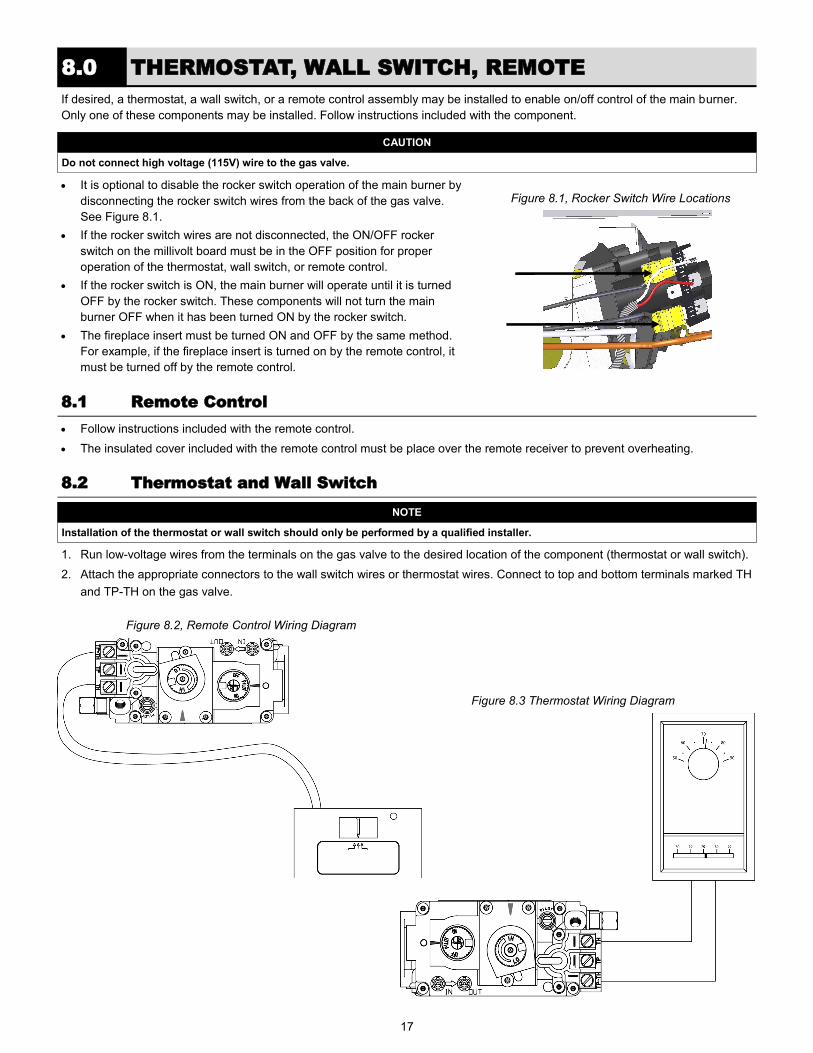
If desired, a thermostat, a wall switch, or a remote control assembly may be installed to enable on/off control of the main burner.
Only one of these components may be installed. Follow instructions included with the component.
Figure 8.1, Rocker Switch Wire Locations It is optional to disable the rocker switch operation of the main burner by
disconnecting the rocker switch wires from the back of the gas valve.
See Figure 8.1.
If the rocker switch wires are not disconnected, the ON/OFF rocker
switch on the millivolt board must be in the OFF position for proper
operation of the thermostat, wall switch, or remote control.
If the rocker switch is ON, the main burner will operate until it is turned
OFF by the rocker switch. These components will not turn the main
burner OFF when it has been turned ON by the rocker switch.
The fireplace insert must be turned ON and OFF by the same method.
For example, if the fireplace insert is turned on by the remote control, it
must be turned off by the remote control.
18
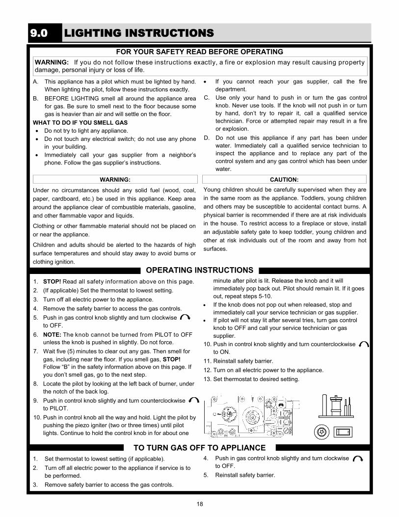
WARNING: If you do not follow these instructions exactly, a fire or explosion may result causing property damage, personal injury or loss of life.
FOR YOUR SAFETY READ BEFORE OPERATING
A. This appliance has a pilot which must be lighted by hand.
When lighting the pilot, follow these instructions exactly.
B. BEFORE LIGHTING smell all around the appliance area
for gas. Be sure to smell next to the floor because some
gas is heavier than air and will settle on the floor.
WHAT TO DO IF YOU SMELL GAS
Do not try to light any appliance.
Do not touch any electrical switch; do not use any phone
in your building.
Immediately call your gas supplier from a neighbor’s
phone. Follow the gas supplier’s instructions.
If you cannot reach your gas supplier, call the fire
department.
C. Use only your hand to push in or turn the gas control
knob. Never use tools. If the knob will not push in or turn
by hand, don’t try to repair it, call a qualified service
technician. Force or attempted repair may result in a fire
or explosion.
D. Do not use this appliance if any part has been under
water. Immediately call a qualified service technician to
inspect the appliance and to replace any part of the
control system and any gas control which has been under
water.
Under no circumstances should any solid fuel (wood, coal,
paper, cardboard, etc.) be used in this appliance. Keep area
around the appliance clear of combustible materials, gasoline,
and other flammable vapor and liquids.
Clothing or other flammable material should not be placed on
or near the appliance.
Children and adults should be alerted to the hazards of high
surface temperatures and should stay away to avoid burns or
clothing ignition.
Young children should be carefully supervised when they are
in the same room as the appliance. Toddlers, young children
and others may be susceptible to accidental contact burns. A
physical barrier is recommended if there are at risk individuals
in the house. To restrict access to a fireplace or stove, install
an adjustable safety gate to keep toddler, young children and
other at risk individuals out of the room and away from hot
surfaces.
OPERATING INSTRUCTIONS
1. STOP! Read all safety information above on this page.
2. (If applicable) Set the thermostat to lowest setting.
3. Turn off all electric power to the appliance.
4. Remove the safety barrier to access the gas controls.
5. Push in gas control knob slightly and turn clockwise
to OFF.
6. NOTE: The knob cannot be turned from PILOT to OFF
unless the knob is pushed in slightly. Do not force.
7. Wait five (5) minutes to clear out any gas. Then smell for
gas, including near the floor. If you smell gas, STOP!
Follow “B” in the safety information above on this page. If
you don’t smell gas, go to the next step.
8. Locate the pilot by looking at the left back of burner, under
the notch of the back log.
9. Push in control knob slightly and turn counterclockwise
to PILOT.
10. Push in control knob all the way and hold. Light the pilot by
pushing the piezo igniter (two or three times) until pilot
lights. Continue to hold the control knob in for about one
minute after pilot is lit. Release the knob and it will
immediately pop back out. Pilot should remain lit. If it goes
out, repeat steps 5-10.
If the knob does not pop out when released, stop and
immediately call your service technician or gas supplier.
If pilot will not stay lit after several tries, turn gas control
knob to OFF and call your service technician or gas
supplier.
10. Push in control knob slightly and turn counterclockwise
to ON.
11. Reinstall safety barrier.
12. Turn on all electric power to the appliance.
13. Set thermostat to desired setting.
1. Set thermostat to lowest setting (if applicable).
2. Turn off all electric power to the appliance if service is to
be performed.
3. Remove safety barrier to access the gas controls.
4. Push in gas control knob slightly and turn clockwise
to OFF.
5. Reinstall safety barrier.
TO TURN GAS OFF TO APPLIANCE
WARNING: CAUTION:
9.0 LIGHTING INSTRUCTIONS
19
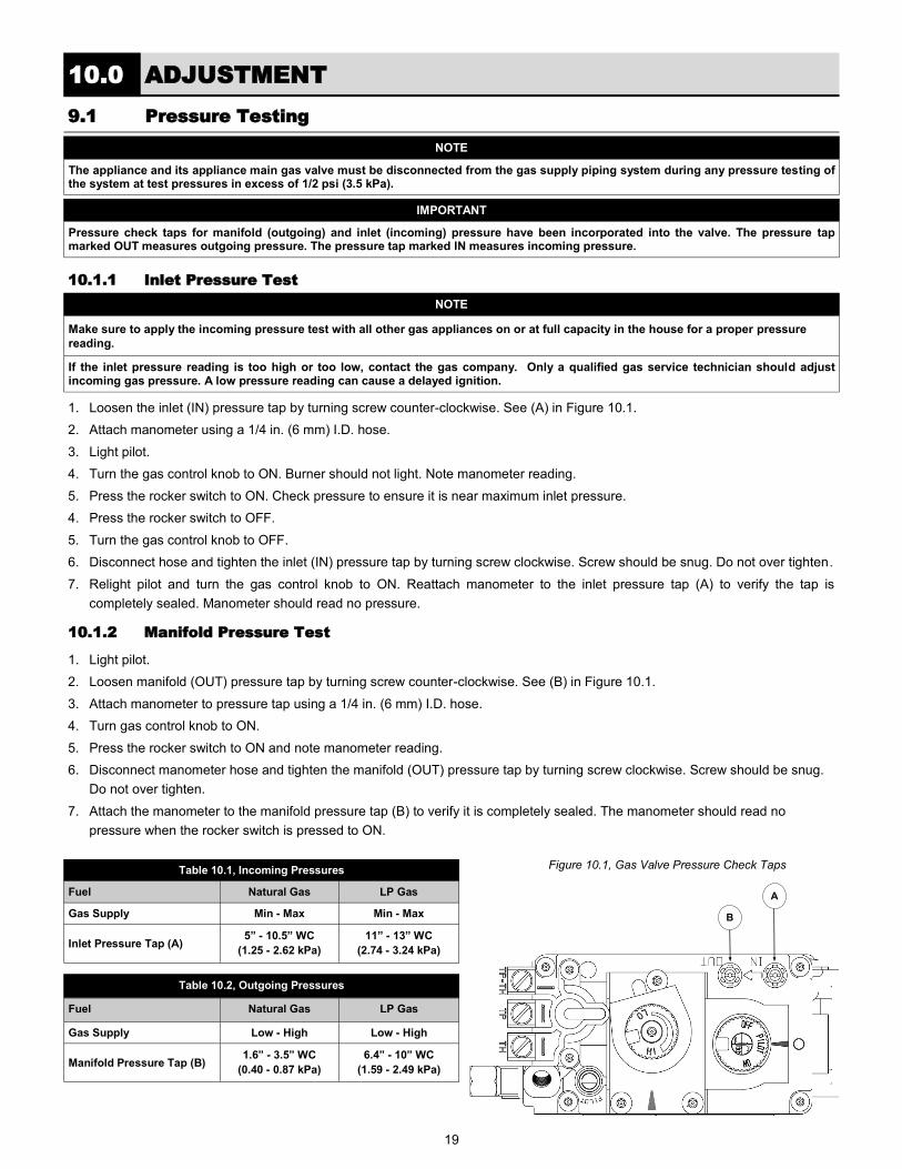
Figure 10.1, Gas Valve Pressure Check Taps
IMPORTANT
Pressure check taps for manifold (outgoing) and inlet (incoming) pressure have been incorporated into the valve. The pressure tap marked OUT measures outgoing pressure. The pressure tap marked IN measures incoming pressure.
NOTE
The appliance and its appliance main gas valve must be disconnected from the gas supply piping system during any pressure testing of the system at test pressures in excess of 1/2 psi (3.5 kPa).
NOTE
Make sure to apply the incoming pressure test with all other gas appliances on or at full capacity in the house for a proper pressure
reading.
If the inlet pressure reading is too high or too low, contact the gas company. Only a qualified gas service technician should adjust incoming gas pressure. A low pressure reading can cause a delayed ignition.
1. Loosen the inlet (IN) pressure tap by turning screw counter-clockwise. See (A) in Figure 10.1.
2. Attach manometer using a 1/4 in. (6 mm) I.D. hose.
3. Light pilot.
4. Turn the gas control knob to ON. Burner should not light. Note manometer reading.
5. Press the rocker switch to ON. Check pressure to ensure it is near maximum inlet pressure.
4. Press the rocker switch to OFF.
5. Turn the gas control knob to OFF.
6. Disconnect hose and tighten the inlet (IN) pressure tap by turning screw clockwise. Screw should be snug. Do not over tighten.
7. Relight pilot and turn the gas control knob to ON. Reattach manometer to the inlet pressure tap (A) to verify the tap is
completely sealed. Manometer should read no pressure.
1. Light pilot.
2. Loosen manifold (OUT) pressure tap by turning screw counter-clockwise. See (B) in Figure 10.1.
3. Attach manometer to pressure tap using a 1/4 in. (6 mm) I.D. hose.
4. Turn gas control knob to ON.
5. Press the rocker switch to ON and note manometer reading.
6. Disconnect manometer hose and tighten the manifold (OUT) pressure tap by turning screw clockwise. Screw should be snug.
Do not over tighten.
7. Attach the manometer to the manifold pressure tap (B) to verify it is completely sealed. The manometer should read no
pressure when the rocker switch is pressed to ON.
10.0 ADJUSTMENT
9.1 Pressure Testing
10.1.1 Inlet Pressure Test
10.1.2 Manifold Pressure Test
Table 10.1, Incoming Pressures
Fuel Natural Gas LP Gas
Gas Supply Min - Max Min - Max
Inlet Pressure Tap (A) 5” - 10.5” WC
(1.25 - 2.62 kPa)
11” - 13” WC
(2.74 - 3.24 kPa)
Table 10.2, Outgoing Pressures
Fuel Natural Gas LP Gas
Gas Supply Low - High Low - High
Manifold Pressure Tap (B) 1.6” - 3.5” WC
(0.40 - 0.87 kPa)
6.4” - 10” WC
(1.59 - 2.49 kPa)
A
B
20
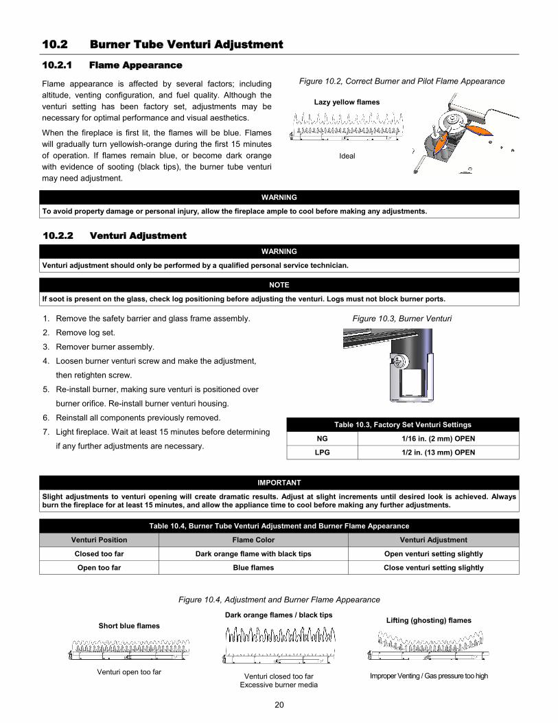
Flame appearance is affected by several factors; including
altitude, venting configuration, and fuel quality. Although the
venturi setting has been factory set, adjustments may be
necessary for optimal performance and visual aesthetics.
When the fireplace is first lit, the flames will be blue. Flames
will gradually turn yellowish-orange during the first 15 minutes
of operation. If flames remain blue, or become dark orange
with evidence of sooting (black tips), the burner tube venturi
may need adjustment.
IMPORTANT
Slight adjustments to venturi opening will create dramatic results. Adjust at slight increments until desired look is achieved. Always burn the fireplace for at least 15 minutes, and allow the appliance time to cool before making any further adjustments.
Figure 10.3, Burner Venturi
WARNING
To avoid property damage or personal injury, allow the fireplace ample to cool before making any adjustments.
10.2 Burner Tube Venturi Adjustment
10.2.1 Flame Appearance
Table 10.3, Factory Set Venturi Settings
NG 1/16 in. (2 mm) OPEN
LPG 1/2 in. (13 mm) OPEN
10.2.2 Venturi Adjustment
Figure 10.2, Correct Burner and Pilot Flame Appearance
Ideal
Lazy yellow flames
1. Remove the safety barrier and glass frame assembly.
2. Remove log set.
3. Remover burner assembly.
4. Loosen burner venturi screw and make the adjustment,
then retighten screw.
5. Re-install burner, making sure venturi is positioned over
burner orifice. Re-install burner venturi housing.
6. Reinstall all components previously removed.
7. Light fireplace. Wait at least 15 minutes before determining
if any further adjustments are necessary.
Table 10.4, Burner Tube Venturi Adjustment and Burner Flame Appearance
Venturi Position Flame Color Venturi Adjustment
Closed too far Dark orange flame with black tips Open venturi setting slightly
Open too far Blue flames Close venturi setting slightly
Venturi open too far
Short blue flames
Venturi closed too far Excessive burner media
Dark orange flames / black tips
Improper Venting / Gas pressure too high
Lifting (ghosting) flames
Figure 10.4, Adjustment and Burner Flame Appearance
WARNING
Venturi adjustment should only be performed by a qualified personal service technician.
NOTE
If soot is present on the glass, check log positioning before adjusting the venturi. Logs must not block burner ports.
21
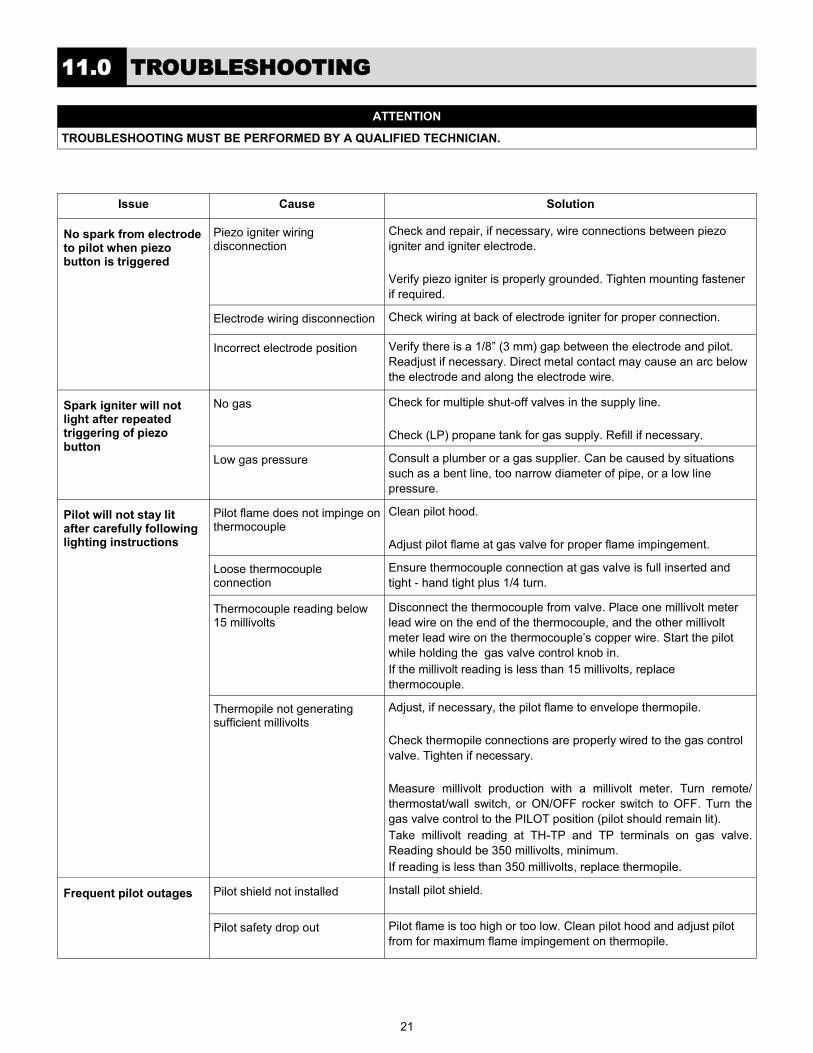
11.0 TROUBLESHOOTING
Issue Cause Solution
No spark from electrode to pilot when piezo button is triggered
Piezo igniter wiring disconnection
Check and repair, if necessary, wire connections between piezo
igniter and igniter electrode.
Verify piezo igniter is properly grounded. Tighten mounting fastener
if required.
Electrode wiring disconnection Check wiring at back of electrode igniter for proper connection.
Incorrect electrode position Verify there is a 1/8” (3 mm) gap between the electrode and pilot.
Readjust if necessary. Direct metal contact may cause an arc below
the electrode and along the electrode wire.
Spark igniter will not light after repeated triggering of piezo button
No gas Check for multiple shut-off valves in the supply line.
Check (LP) propane tank for gas supply. Refill if necessary.
Low gas pressure Consult a plumber or a gas supplier. Can be caused by situations
such as a bent line, too narrow diameter of pipe, or a low line
pressure.
Pilot will not stay lit after carefully following lighting instructions
Pilot flame does not impinge on thermocouple
Clean pilot hood.
Adjust pilot flame at gas valve for proper flame impingement.
Loose thermocouple connection
Ensure thermocouple connection at gas valve is full inserted and
tight - hand tight plus 1/4 turn.
Thermocouple reading below 15 millivolts
Disconnect the thermocouple from valve. Place one millivolt meter
lead wire on the end of the thermocouple, and the other millivolt
meter lead wire on the thermocouple’s copper wire. Start the pilot
while holding the gas valve control knob in.
If the millivolt reading is less than 15 millivolts, replace
thermocouple.
Thermopile not generating sufficient millivolts
Adjust, if necessary, the pilot flame to envelope thermopile.
Check thermopile connections are properly wired to the gas control
valve. Tighten if necessary.
Measure millivolt production with a millivolt meter. Turn remote/
thermostat/wall switch, or ON/OFF rocker switch to OFF. Turn the
gas valve control to the PILOT position (pilot should remain lit).
Take millivolt reading at TH-TP and TP terminals on gas valve.
Reading should be 350 millivolts, minimum.
If reading is less than 350 millivolts, replace thermopile.
Frequent pilot outages Pilot shield not installed Install pilot shield.
Pilot safety drop out Pilot flame is too high or too low. Clean pilot hood and adjust pilot
from for maximum flame impingement on thermopile.
ATTENTION
TROUBLESHOOTING MUST BE PERFORMED BY A QUALIFIED TECHNICIAN.
22
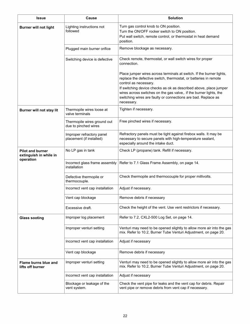
Issue Cause Solution
Burner will not light Lighting instructions not followed
Turn gas control knob to ON position.
Turn the ON/OFF rocker switch to ON position.
Put wall switch, remote control, or thermostat in heat demand
position.
Plugged main burner orifice Remove blockage as necessary.
Switching device is defective Check remote, thermostat, or wall switch wires for proper
connection.
Place jumper wires across terminals at switch. If the burner lights,
replace the defective switch, thermostat, or batteries in remote
control as necessary.
If switching device checks as ok as described above, place jumper
wires across switches on the gas valve,. if the burner lights, the
switching wires are faulty or connections are bad. Replace as
necessary.
Burner will not stay lit Thermopile wires loose at valve terminals
Tighten if necessary.
Thermopile wires ground out due to pinched wires
Free pinched wires if necessary.
Improper refractory panel placement (if installed)
Refractory panels must be tight against firebox walls. It may be
necessary to secure panels with high-temperature sealant,
especially around the intake duct.
Pilot and burner extinguish in while in operation
No LP gas in tank Check LP (propane) tank. Refill if necessary.
Incorrect glass frame assembly installation
Refer to 7.1 Glass Frame Assembly, on page 14.
Defective thermopile or thermocouple.
Check thermopile and thermocouple for proper millivolts.
Incorrect vent cap installation Adjust if necessary.
Vent cap blockage Remove debris if necessary
Excessive draft. Check the height of the vent. Use vent restrictors if necessary.
Glass sooting Improper log placement Refer to 7.2, CXL2-500 Log Set, on page 14.
Improper venturi setting Venturi may need to be opened slightly to allow more air into the gas mix. Refer to 10.2, Burner Tube Venturi Adjustment, on page 20.
Incorrect vent cap installation Adjust if necessary
Vent cap blockage Remove debris if necessary
Improper venturi setting Venturi may need to be opened slightly to allow more air into the gas mix. Refer to 10.2, Burner Tube Venturi Adjustment, on page 20.
Flame burns blue and lifts off burner
Incorrect vent cap installation Adjust if necessary
Blockage or leakage of the vent system.
Check the vent pipe for leaks and the vent cap for debris. Repair vent pipe or remove debris from vent cap if necessary.

23
12.0 MAINTENANCE
The burner assembly may be removed for easier access. Refer to 7.3 Control Board, on page 15 for removal and reinstallation.
CAUTION
Label all wires prior to disconnection when servicing controls. Wiring errors can cause improper and dangerous operation. Verify proper operation after servicing.
12.1 Burner and Pilot System
Performed by Frequency Action
Qualified Service Person Annually Vacuum all components of the burner system
Visually check burner ports for blockage, especially near the pilot
Visually check pilot light when in operation. Flames should steady, not lifting or floating.
12.2 Fans
Performed by Frequency Action
Qualified Service Person Every 6 months Disconnect fans from electrical current, and vacuum. The bearings are sealed and require no oiling.
12.3 Vent System
NOTE
If the vent-air intake system is disassembled for any reason, reinstall per instructions provided with installation. Refer to section 5.6, on page 12.
Performed by Frequency Action
Qualified Service Agency Annually Examination of the vent system is required. The flow of combustion and ventilation air must not be obstructed.
IMPORTANT
Installation and repair shall only be done by a qualified service person. The appliance should be inspected by a qualified service person before use. Annual inspection by a qualified service person is required to maintain warranty.
The compartment below the firebox must be cleaned at least once a year. More frequent cleaning may be required due to excessive lint from carpeting, bedding materials, etc. It is imperative that the burner and control compartments of the appliance be kept clean. Use a vacuum to clean all components.
Burner Orifice Pilot Burner Ports
Figure 12.1, Burner and Pilot System
24
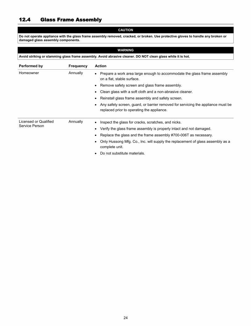
12.4 Glass Frame Assembly
Performed by Frequency Action
Homeowner Annually Prepare a work area large enough to accommodate the glass frame assembly
on a flat, stable surface.
Remove safety screen and glass frame assembly.
Clean glass with a soft cloth and a non-abrasive cleaner.
Reinstall glass frame assembly and safety screen.
Any safety screen, guard, or barrier removed for servicing the appliance must be
replaced prior to operating the appliance.
Licensed or Qualified Service Person
Annually Inspect the glass for cracks, scratches, and nicks.
Verify the glass frame assembly is properly intact and not damaged.
Replace the glass and the frame assembly #700-006T as necessary.
Only Hussong Mfg. Co., Inc. will supply the replacement of glass assembly as a
complete unit.
Do not substitute materials.
CAUTION
Do not operate appliance with the glass frame assembly removed, cracked, or broken. Use protective gloves to handle any broken or damaged glass assembly components.
WARNING
Avoid striking or slamming glass frame assembly. Avoid abrasive cleaner. DO NOT clean glass while it is hot.
25
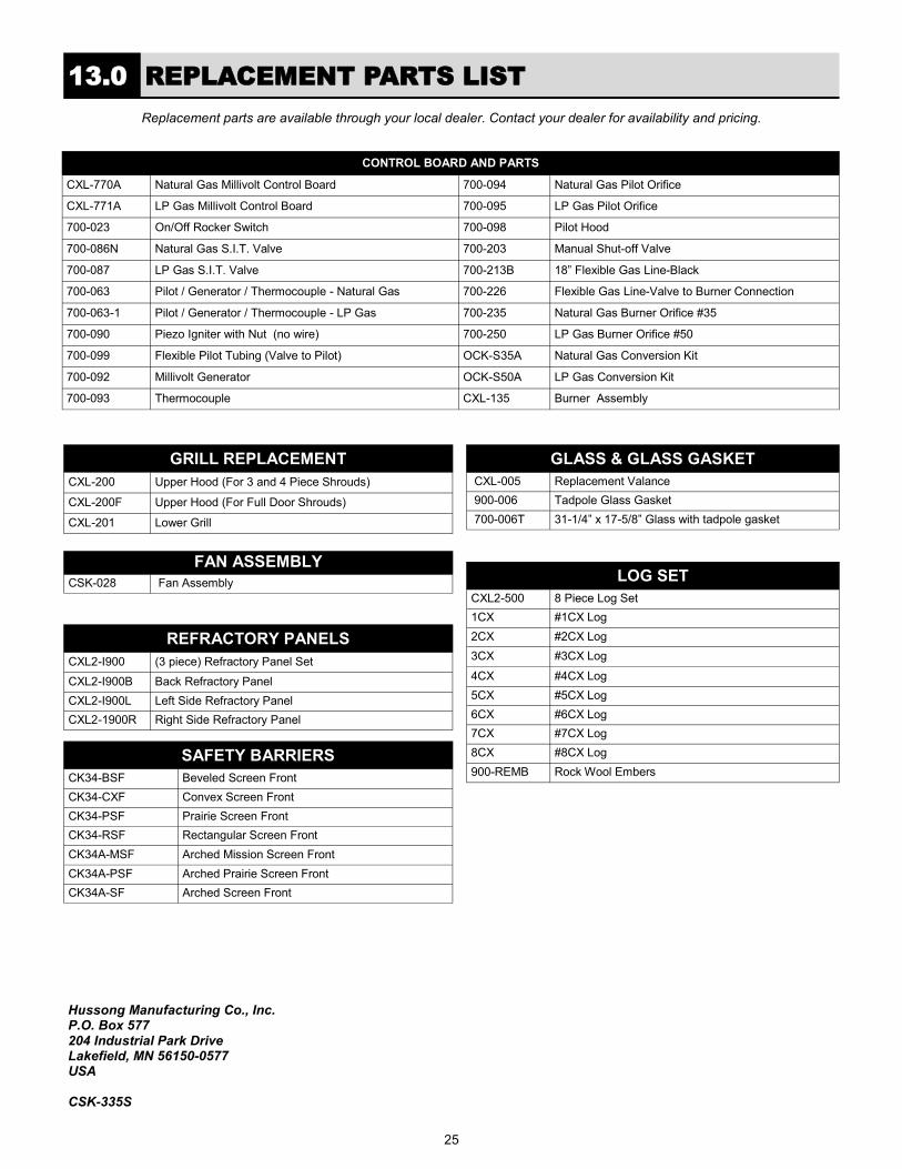
GRILL REPLACEMENT
CXL-200 Upper Hood (For 3 and 4 Piece Shrouds)
CXL-200F Upper Hood (For Full Door Shrouds)
CXL-201 Lower Grill
REFRACTORY PANELS
CXL2-I900 (3 piece) Refractory Panel Set
CXL2-I900B Back Refractory Panel
CXL2-I900L Left Side Refractory Panel
CXL2-1900R Right Side Refractory Panel
FAN ASSEMBLY
CSK-028 Fan Assembly
GLASS & GLASS GASKET
CXL-005 Replacement Valance
900-006 Tadpole Glass Gasket
700-006T 31-1/4” x 17-5/8” Glass with tadpole gasket
LOG SET
CXL2-500 8 Piece Log Set
1CX #1CX Log
2CX #2CX Log
3CX #3CX Log
4CX #4CX Log
5CX #5CX Log
6CX #6CX Log
7CX #7CX Log
8CX #8CX Log
900-REMB Rock Wool Embers
Replacement parts are available through your local dealer. Contact your dealer for availability and pricing.
Hussong Manufacturing Co., Inc. P.O. Box 577 204 Industrial Park Drive Lakefield, MN 56150-0577 USA CSK-335S
13.0 REPLACEMENT PARTS LIST
SAFETY BARRIERS
CK34-BSF Beveled Screen Front
CK34-CXF Convex Screen Front
CK34-PSF Prairie Screen Front
CK34-RSF Rectangular Screen Front
CK34A-MSF Arched Mission Screen Front
CK34A-PSF Arched Prairie Screen Front
CK34A-SF Arched Screen Front
CONTROL BOARD AND PARTS
CXL-770A Natural Gas Millivolt Control Board 700-094 Natural Gas Pilot Orifice
CXL-771A LP Gas Millivolt Control Board 700-095 LP Gas Pilot Orifice
700-023 On/Off Rocker Switch 700-098 Pilot Hood
700-086N Natural Gas S.I.T. Valve 700-203 Manual Shut-off Valve
700-087 LP Gas S.I.T. Valve 700-213B 18” Flexible Gas Line-Black
700-063 Pilot / Generator / Thermocouple - Natural Gas 700-226 Flexible Gas Line-Valve to Burner Connection
700-063-1 Pilot / Generator / Thermocouple - LP Gas 700-235 Natural Gas Burner Orifice #35
700-090 Piezo Igniter with Nut (no wire) 700-250 LP Gas Burner Orifice #50
700-099 Flexible Pilot Tubing (Valve to Pilot) OCK-S35A Natural Gas Conversion Kit
700-092 Millivolt Generator OCK-S50A LP Gas Conversion Kit
700-093 Thermocouple CXL-135 Burner Assembly
This limited 10 Year Warranty will not become effective until the Warranty Registration Form has been completed and mailed to Hussong Manufacturing Co., Inc., P.O. Box 577, Lakefield, MN 56150. This registration form must be received within 30 days of installation. Failure to do so may result in delayed warranty coverage and submission of proof of purchase will be required. Hussong Manufacturing Co., Inc. warranties to the original purchaser of this Kozy Heat Fireplace, that it is free of defects in materials and workmanship at the time of manufacture. Subject to the following conditions & requirements, Hussong Manufacturing Co., Inc. extends the following limited warranty under normal use and service, with respect to the Kozy Heat line of gas burning fireplaces.
Effective September 01, 2011
Year 1
Subject to the conditions & requirements listed below, within the first year from date of purchase, Hussong Manufacturing Co., Inc. shall, at its discretion, replace or repair any such defect in material or workmanship, at Hussong Manufacturing Co., Inc.’s expense, including reasonable labor costs to repair or replace the defective component, if a factory pre-authorization is given for the repair.
Subject to the conditions & requirements listed below, beginning with the first day of the second year and continuing through the tenth year, Hussong Manufacturing Co., Inc., will at its discretion, provide repair or replacement parts at current list prices for any defect in material or workmanship of components, including optional components and accessories (if available). Hussong Manufacturing Co., Inc. shall not be responsible for any installation, labor, transportation of other indirect costs.
Years 2 through 10
To make a claim under this warranty, the purchaser must first contact the dealer/installer from whom the fireplace was purchased. This limited warranty will be void if the fireplace is not installed by a qualified installer and according to the installation instructions. Use of unauthorized components will make this warranty null and void. This limited warranty also is void if the fireplace is not operated, at all times, according to the operating instructions furnished. This warranty is limited to defects in material and workmanship. It does not apply to any product that has been subject to negligence, misapplication, improper installation. No person is authorized to extend the time of this warranty or to accept on Hussong Manufacturing Co., Inc.’s behalf any additional obligation of liability connected with the unit. It is expressly agreed and understood that this warranty is Hussong Manufacturing Co., Inc.’s sole obligation and purchaser’s exclusive remedy for defective fireplace equipment. Hussong Manufacturing Co., Inc. shall not be liable for any consequential, incidental or contingent damages whatsoever. The foregoing warranty is exclusive and in lieu of all other expressed warranties. Hussong Manufacturing Co., Inc. shall not be held to implied warranties or merchantability and fitness for a particular purpose. This warranty replaces all previous warranty policies. Some states do not allow the exclusion or limitation of incidental or consequential damages or limitations on how long an implied warranty lasts, so the above limitations or exclusions may not apply to you. This warranty gives you specific legal rights and you may also have other rights which vary from state to state. Hussong Manufacturing Co., Inc. reserves the right to make changes at any time, without notice, in design, material, specifications and prices. Hussong Manufacturing Co., Inc. reserves the right to discontinue models and products.
1. You are the original purchaser. This warranty is not transferable. 2. Installation of the fireplace is performed by a qualified installer. 3. Installation and operation must comply with installation and operation instructions. 4. Paint and glass gaskets are covered for 30 days from date of purchase. 5. Remote controls and all optional accessories are covered for 1 year from date of purchase. 6. This warranty does not offer coverage for Light Bulbs or Batteries (whether factory, dealer or installer supplied). This includes any damage
stemming from either component’s nonuse. 7. Components broken, (including glass panels), during shipping, careless handling of components, or defects resulting from improper
installation, misuse of the fireplace and components are not covered under this warranty. 8. This warranty does not cover any part of the fireplace or any components which have been exposed to or submerged underwater. 9. Hussong Manufacturing Co., Inc. must be notified by the dealer the fireplace was purchased from or a qualified installer/service technician of
the defect. 10. Annual service of the fireplace as required in the installation manual, is performed by a qualified installer/service technician.
(Copies of such service records may be required to claim a warranty). 11. All previous warranty/service has been performed by a qualified installer or service technician.
(Copies of such service records may be required to claim a warranty).
LIMITED WARRANTY
Kozy Heat Limited 10 Year Warranty
Limitation of Liability
Warranty Conditions and Requirements
25
36
THIS LIFETIME WARRANTY COVERAGE WILL BE EXTENDED AS DESCRIBED BELOW PROVIDED ALL WARRANTY CONDITIONS AND REQUIREMENTS ARE MET AS OUTLINED IN THE 10 YEAR LIMITED WARRANTY POLICY.
LIFETIME WARRANTY IS EXTENDED AS FOLLOWS: Hussong Manufacturing Co., Inc. warranties to the original purchaser that the firebox, heat exchanger, fiber logs, burner tube and glass panel of this Kozy Heat Fireplace will not be defective in material or workmanship under normal use and service for as long as you own this product. If any of these components fail due to defects in material and workmanship under normal use and service, Hussong Manufacturing, Co., Inc. will, at its sole discretion, repair or replace the defective component. This LIFETIME WARRANTY does not cover any installation, labor, transportation or other indirect cost arising from defective components.
This Lifetime Warranty will be void if the fireplace is not installed by a qualified installer and according to the installation instructions. Use of unauthorized components will make this warranty null and void. This Lifetime Warranty also is void if the fireplace is not operated, at all times, according to the operating instructions furnished. This warranty is limited to defects in material and workmanship of components specified. It does not apply to any product that has been subject to negligence, misapplication, improper installation. No person is authorized to extend the time of this Lifetime Warranty or to accept on Hussong Manufacturing Co., Inc.’s behalf any additional obligation of liability connected with the unit. Hussong Manufacturing Co., Inc. may fully discharge all obligations with respect to this Lifetime Warranty by refunding the wholesale price of the defective component(s). It is expressly agreed and understood that this Lifetime Warranty is Hussong Manufacturing Co., Inc.’s sole obligation and original purchaser’s exclusive remedy for defective fireplace equipment. Hussong Manufacturing Co., Inc. shall not be liable for any consequential, incidental or contingent damages whatsoever other than those incurred by Hussong Manufacturing Co., Inc. to repair or replace the defective component. The foregoing warranty is exclusive and in lieu of all other expressed warranties. Hussong Manufacturing Co., Inc. shall not be held to implied warranties, including but not limited to the implied warranties or merchantability and fitness for a particular purpose. This lifetime warranty replace all previous lifetime warranty policies. Hussong Manufacturing Co., Inc. reserves the right to make changes at any time, without notice, in design, material, specifications and prices. Hussong Manufacturing Co., Inc. reserves the right to discontinue models and products.
PURCHASER NAME: INSTALLATION DATE:
ADDRESS: MODEL #:
SERIAL #:
TELEPHONE:
INSTALLER NAME:
ADDRESS:
TELEPHONE:
CUT ALONG DOTTED LINE
To activate this Lifetime Warranty coverage, this registration card must be completed and mailed with your completed 10 Year Limited Warranty form within 30 days of installation to the following address: Hussong Manufacturing Co., Inc. P.O. Box 577 204 Industrial Park Drive Lakefield, MN 56150-0577
September 2011
LIFETIME WARRANTY
Lifetime Warranty Coverage
Limitation of Liability
26