Embed Size (px)
Citation preview

OPERATOR’S MANUAL& PARTS DRAWINGS
HUSTLER 93043884” FLEX DECK
07/19/1109.10073
PO Box 7000Hesston, Kansas67062-2097

TABLE OF CONTENTS
2
INTRODUCTION PAGE 4To the New Owner ..................................................................................................................................4Warranty Registration ............................................................................................................................4Model and Serial Number ......................................................................................................................4Parts and Service ...................................................................................................................................4Using Your Manual .................................................................................................................................5
SAFETY PAGE 6Safety Decals .........................................................................................................................................6General Safety Procedures ....................................................................................................................8Training Required ...................................................................................................................................8Personal Protective Equipment Requirements ......................................................................................8Operating Safely ....................................................................................................................................8Preventing Accidents ..............................................................................................................................9Keep Riders Off ....................................................................................................................................10Truck Or Trailer Transport ....................................................................................................................10Maintenance .........................................................................................................................................10Hydraulic Safety ................................................................................................................................... 11Flex Deck Safety Procedures ...............................................................................................................12Cutting Unit Safety ...............................................................................................................................12
GENERAL OPERATION PAGE 13Daily Inspection ....................................................................................................................................13Attaching ..............................................................................................................................................13Detaching .............................................................................................................................................14Rear Counterbalance Weights .............................................................................................................15Mowing and Operating Procedure .......................................................................................................15Transport of Mower ..............................................................................................................................15Cutting Height Adjustment ....................................................................................................................15Mower Front Wheel Path Adjustment ...................................................................................................16Anti-Scalp Roller Adjustment ................................................................................................................16Mulching Kit (Optional Accessory) .......................................................................................................16
SERVICE PAGE 17Cleaning and General Maintenance.....................................................................................................17Deck Flip-Up Procedure (Service Position) ..........................................................................................17Mower Blade Inspection/Replacement .................................................................................................18Mower Blade Sharpening .....................................................................................................................18Drive Belt Inspection/Replacement ......................................................................................................18Drive Belt Tensioning Adjustments .......................................................................................................19Tire Pressure ........................................................................................................................................19Storage .................................................................................................................................................19Deck Leveling Procedure .....................................................................................................................20Lubrication Locations ...........................................................................................................................22Gearbox ...............................................................................................................................................23Maintenance Schedule .........................................................................................................................24Maintenance Checklist .........................................................................................................................25Dimensions ..........................................................................................................................................26

TABLE OF CONTENTS
3
PARTS PAGE 28Decks & Connector Links .....................................................................................................................28Carrier Frame .......................................................................................................................................30Hitch Arms & Hitch Frame Shields .......................................................................................................32Drive Shaft & Gearbox .........................................................................................................................34Deck Belts ............................................................................................................................................36Spindles ...............................................................................................................................................38Carrier & Side Deck Shields .................................................................................................................40Front Anti-Scalp Rollers .......................................................................................................................42Rear Rollers .........................................................................................................................................44Discharge Defl ectors & Rear Belting ....................................................................................................46Deck Wing Lift Arms .............................................................................................................................48Deck Wing Lift Arm Hydraulics .............................................................................................................50Mulch Kit ..............................................................................................................................................52
WARRANTY PAGE 54

Introduction - 4
This manual applies to the following Hustler equipment lines: Hustler 84” Flex DeckTo the New OwnerThe purpose of this manual is to assist owners and operators in maintaining and operating the Hustler Flex Deck. Please read it carefully; information and instructions furnished can help you achieve years of dependable performance. It is divided into sections for convenient reference of the appropriate section. Keep this manual with the machine at all times. The manual should remain with the machine even if it is sold. If this manual becomes damaged or unreadable, it should be replaced immediately. Contact your Hustler dealer for a replacement.When using a Hustler attachment, be sure to read and follow the safety and operating instructions of both the power unit and the attachment being used to ensure the safest operation possible.It is the owner’s responsibility to make certain that the operators and mechanics read and understand this manual and all decals before operating this machine. It is also the owner’s responsibility to make certain that the operators and mechanics are qualifi ed and physically able individuals, properly trained in the operation of this equipment. All operators and mechanics must become familiar with the safe operation of the equipment, operator controls, and safety signs.The owner/user can prevent and is responsible for accidents or injuries occurring to themselves, other people, or property.
Warranty RegistrationThe completed Warranty Registration and Delivery form must be sent to Hustler Turf Equipment within ten (10) days of delivery to validate your warranty protection. As the new equipment owner, you are expected to see that the form is completed and forwarded to Hustler Turf Equipment at time of delivery. The warranty registration form can also be accomplished electronically by the Hustler dealer to validate the warranty.This form must be on fi le for validation before any warranty claim applications can be processed by Hustler Turf Equipment.Be sure to register the power unit plus each attachment that displays a model and serial identifi cation num-ber plate with Hustler Turf Equipment.IMPORTANT: Any unauthorized modifi cation, alteration, or use of non-approved attachments voids the warranty and releases Hustler Turf Equipment from any liability arising from subsequent use of this equip-ment. Do not use or operate any attachment not approved by Hustler Turf Equipment.
Model and Serial NumberModel and serial numbers are found on the serial identifi cation plate, located on the left carrier arm. These numbers are required on the Warranty Registration form. They will also assure you of the correct service parts when replacement becomes necessary. Please fi ll in the following information for future reference.
Date of Purchase: ____________________ Dealer Name: _________________________Dealer Phone #: ______________________ Dealer Fax #: __________________________Dealer Address: ____________________________________________________________Model Number: ______________________ Serial Number: _________________________Parts and ServiceUse original Hustler replacement parts only. These parts are available through your local Hustler dealer. To obtain prompt, effi cient service, always provide the following information when ordering parts.1. Correct part description.2. Correct model number.3. Correct serial number.All warranty repair and service must be handled through an authorized Hustler dealer. Arrangements should be made through your local service center.
INTRODUCTION

INTRODUCTION
Introduction - 5
Using Your ManualGeneral operation, adjustment, and maintenance guidance is outlined for both the experienced and novice Hus-tler user. Operating conditions vary considerably and cannot all be addressed individually. Through experience, however, operators should fi nd no diffi culty in developing good operating skills suitable to most conditions.Directions used in this manual, for example RIGHT or LEFT, refer to directions when seated on power unit facing forward, unless stated otherwise.Photographs and illustrations used were current at the time of printing, but subsequent production changes may cause your machine to vary slightly in detail. Hustler Turf Equipment reserves the right to redesign and change the machine as deemed necessary, without notifi cation. If a change has been made to your machine which is not refl ected in this owner’s manual, see you Hustler dealer for current information and parts.Throughout this manual, you will encounter special messages and symbols that identify potential safety concerns to help you as well as others avoid personal injury or damage to the equipment.
This safety alert symbol is used to call attention to a message intended to provide a reasonable degree of PERSONAL SAFETY for operators and other persons during the normal operation and servicing of this equipment. Obey all safety messages that follow this symbol to avoid possible injury or death.
SYMBOL DEFINITIONS
There are three signal words that describe the level of safety concern: Danger, Warning, and Caution. Safety should always be the #1 priority when working on or operating equipment. Accidents are more likely to occur when proper operating procedures are not followed or inexperienced operators are involved.
SIGNAL WORD DEFINITIONS
Denotes a hazard or unsafe practice which COULD result in severe personal injury or death.
Denotes immediate hazards which WILL result in severe personal injury or death.
This manual may also use two other word to highlight information. IMPORTANT calls attention to special mechanical information and NOTE: emphasizes general information worthy of special attention.

Safety - 6
Safety DecalsThe following safety decals must be maintained on your Hustler fl ex deck.Keep all safety decals legible. Remove all grease, dirt, and debris from safety decals and instructional labels. If any decals are faded, illegible, or missing, contact your dealer promptly for replacements.When new components are installed, be sure that current safety decals are affi xed to the replacement components.
SAFETY
BB
CC
DD
EE
FF
AA
AA
AAAA
AA
EE
FF
Carrier ArmsCarrier Arms
PTO ShaftPTO Shaft
Anti-scalp RollersAnti-scalp Rollers
Caster Caster WheelsWheels
ShieldsShields
BeltingBeltingRear RollerRear Roller

SAFETY
Safety - 7
Decal Description Part Number QuantityA Warning, Deck Safety 07.0601603 5B Warning, Rotating Drive shaft 07.0601623 1C Warning, Read Owner’s Manual 07.0601625 1D Warning, Fluid Under Pressure 07.0601968 1E Warning, Thrown Objects 07.0602054 2F Warning, Pinch Point 07.0602987 2
WARNING:Thrown objects
DANGER:Rotating blades, pulleys, & belts
• Always maintain a safe distance from people and pets when mowing.
• Always stop machine if someone enters the area.
• Keep hands, feet, and clothing away.• Keep shields or covers in place
while machine is in operation.
WARNING: Rotating driveshaft!
• Keep hands, feet, and clothing clear of this area.
• Keep a safe distance from the machine.• Keep shields or covers in place while
machine is in operation.
WARNING: Read Owner’s Manual before attempting to operate or service this machine.
Wear ear protection, eye protection, and safety shoes when operating this equipment.
WARNING: Pinch points. Keep hands and feet clear. Moving parts can crush or cut.
WARNING: Thrown objects
Never operate the mower deck with rear defl ectors damaged, altered, removed, or in raised position.
EEFF
BBAA
CC
WARNING: Fluid under pressure!
• Avoid hydraulic fl uid escaping under pressure.• Hydraulic fl uid escaping under pressure can
penetrate skin.• Hydraulic fl uid escaping under pressure may
have suffi cient force to penetrate skin and cause serious injury. Foreign fl uid injected into the skin must be surgically removed within a few hours by a doctor familiar with this form of injury, or gangrene may result.
• Before applying pressure to the hydraulic sys-tem, make sure all connections are tight and all hoses and lines are in good condition.
• Relieve all pressure in the system before dis-connecting or working on hydraulic lines.
• To fi nd a leak under pressure, use a piece of cardboard or wood - never use your hands.
• To relieve all pressure in the system, lower attachment and turn engine off.
DD

SAFETY
Safety - 8
General Safety Proceduresfor Machine, Attachments, & Accessories
Training Required• All operators and mechanics should read this manual, and be instructed about safe operating and
maintenance procedures. If the operators or mechanics cannot read and under-stand English, it is the owner’s responsibility to explain this material to them.
• Incorrect usage of this machine may result in severe injury. Personnel oper-ating and maintaining it should be trained in proper use and should read the manuals completely and thoroughly before attempting to set up, operate, adjust, or service this machine.
• It is the owner’s responsibility to make certain that the operators and mechanics read and understand this manual and all decals before operating this machine. It is also the owner’s responsibility to make certain that the operators and mechanics are qualifi ed and physi-cally able individuals, properly trained in the operation of this equipment. All operators and mechanics must become familiar with the safe operation of the equipment, operator controls, and safety signs.
• Never allow children or untrained people to operate or service the equipment. Local regulations may restrict the age of the operator.
• The owner/user can prevent and is responsible for accidents or injuries occurring to themselves, other people, or property. The owner should also ensure the operator/mechanic know that they are responsi-ble for their own safety as well as the safety of other persons within the vicinity. Remember, the opera-tor is responsible for accidents or hazards occurring to other people or their property.
• Learn and understand the use of all controls.• Know how to stop the machine and all attachments quickly in the event of an emergency.
Personal Protective Equipment RequirementsIt is the responsibility of the owner to be sure that the operators use the proper personal protective equip-ment while operating the machine. Required personal protective equipment includes, but is not limited to, the following list.
• Wear a certifi ed ear protection device to prevent loss of hearing.• Prevent eye injury by wearing safety glasses while operating the machine.• Closed toe shoes must be worn at all times.• Long pants must be worn at all times.• When operating in dusty conditions, it is recommended that a dust mask be worn.
Operating Safely• Inspect machine before operation. Repair or replace any damaged, worn, or missing parts. Be sure
guards and shields are in proper working condition and are secured in place. Make all necessary adjustments before operating machine.
• Follow daily and weekly checklists, making sure hoses are tightly secured and bolts tightened.• Alterations or modifi cations to this machine can reduce safety and could cause damage to the machine.
Do not alter safety devices or operate with shields or covers removed.• Before each use, verify that all controls function properly and inspect all safety devices. Do not operate
if controls or safety devices are not in proper working condition.• Check parking brake function before operating. Repair or adjust parking brake if necessary.• Observe and follow all safety decals.• All controls are to be operated from the operator’s seat only.• Always wear a seat belt if the machine has a roll cage/bar installed.• Ensure the attachment or accessory is locked or fastened securely to the power unit before operating.• Ensure that all bystanders are clear of the power unit and attachment before operating. Stop machine if
someone enters your work area.• Never turn the PTO switch on unless the PTO shaft is securely connected to a power driven attachment.

SAFETY
Safety - 9
General Safety Proceduresfor Machine, Attachments, & Accessories
• Always be alert to what is happening around you, but do not lose focus on the task you are performing. Always look in the direction the machine is moving.
• Look behind and down before backing up to be sure of a clear path.• Never operate a poorly maintained machine.• Always inspect machine for damage after striking a foreign object. If damage is found, repair machine
immediately. Be sure to stop on level ground, place park brake lever in the brake engaged position, place the PTO lever in the “OFF” position, lower attachment, and remove ignition switch key before leaving operator’s seat to inspect damage.
• Stop operation immediately at any sign of equipment failure. An unusual noise can be a warning of equipment failure or a sign that maintenance is required. Make all necessary repairs before operating machine again.
• If equipped with a high/low range feature, never shift between high and low range while on a slope. Always move the machine to level ground and place the selector lever in park before shifting range.
• Do not leave machine unattended while it is running.• Always park the machine on level ground.• Always shut off engine when connecting attachment drive shaft to the power unit.• Never leave the operator’s seat without lowering the attachment to the ground, setting the parking
brake, shutting off the engine, and removing the ignition key. Make sure all moving parts have come to a complete stop before dismounting.
• Never leave equipment unattended without lowering the attachment to the ground, setting the parking brake, shutting off the engine, and removing the ignition key.
• Always operate in daylight or with adequate working lights.• Never direct the discharge of any attachment in the direction of people, buildings, animals, vehicles, or
other objects of value.• Never discharge material against a wall or obstruction. Material may ricochet back towards the operator.• Use extra caution when approaching blind corners, shrubs, trees, or other objects that may obscure vision.• Always disengage the blades and wait for them to stop before crossing gravel drives, walks, or roads.• Do not run the engine in a building without adequate ventilation.• Do not touch the engine or the muffl er while the engine is running or immediately after stopping the
engine. These areas may be hot enough to cause a burn.• Do not change the engine governor settings or over-speed the engine. Operating engine at excessive
speed may increase the hazard of personal injury.• To reduce the hazard of fi re, keep the battery compartment, engine, and muffl er areas free of grass,
leaves, and excessive grease.• Never put hands or feet under any part of the machine while it is running.Preventing Accidents
• Inspect area to be mowed for hazards such as rocks, metal objects, and other debris which may be thrown or entangled by the mower blades. Remove these objects before mowing.
• Watch out for holes or deep depressions.• Always maintain a safe distance from people and pets when mowing. Always
stop machine if someone enters the area.• Know the work area well before operation. Do not operate where traction or
stability is questionable.• Reduce speed when you are operating over rough ground.• Equipment can cause serious injury and/or death when improperly used. Before operating, know and
understand the operation and safety of the power unit and the attachment being used.
Operating Safely (continued)

SAFETY
Safety - 10
General Safety Proceduresfor Machine, Attachments, & Accessories
• Do not operate machine if you are not in good physical and mental health, if you will be distracted by personal devices, or are under the infl uence of any substance which might impair decision, dexter-ity, or judgment.
• Children are attracted to machine activity. Be aware of children and do not allow them in the working area. Turn off the machine if a child enters the work area.
• Turn off blades when not mowing.• Always keep clear of the mower blades and attachments during their operation.• Never raise the mower deck with the blades engaged to avoid small obstacles, drive over curbs, and so
forth. Disengage PTO before raising the deck.• Follow the manufacturer’s recommendation for wheel weights or rear counterbalance weights.Keep Riders Off• Only allow the operator on the power unit. Keep riders off.• Never allow riders on any attachment or accessory.
Truck Or Trailer Transport• Use care when loading or unloading machine onto a truck or trailer.• Never attempt to back machine onto transport trailer with mower deck or attachment in the raised position.• The parking brake is not suffi cient to lock the machine during transport. Always secure the power unit
and/or attachment to the transporting vehicle.• Shut off fuel supply to power unit during transport on truck or trailer.Maintenance• Keep all safety decals legible. Remove all grease dirt, and debris from safety decals and instructional labels.• If any decals are faded, illegible, or missing, contact your dealer promptly for replacements.• When new components are installed, be sure that current safety decals are affi xed to the replacement
components.• If any component requires replacement, use only original Hustler replacement parts.• Unless specifi cally required, DO NOT have engine running when servicing or making adjustments to
unit. Park machine on level ground. Place park brake lever in the brake engaged position, place the PTO lever in the “OFF” position, lower deck, remove ignition key, and disconnect negative battery cable before doing any maintenance. Wait for all movement to stop before adjusting, cleaning, or repairing. Repairs or maintenance requiring engine power should be performed by trained maintenance person-nel only. To prevent carbon monoxide poisoning, be sure proper ventilation is available when engine must be operated in an enclosed area. Read and observe safety warnings in front of manual.
• Keep all bolts, nuts, screws, and other fasteners properly tightened.• If the power unit, attachment, or accessory requires repairs or adjustments not instructed in the opera-
tor’s or parts manual, the power unit, attachment, or accessory must be taken to an authorized Hustler dealer for service.
• Except when changing or checking belts, always keep belt covers on mower deck for safety, as well as cleanliness.
• Never perform maintenance on the power unit and/or attachment if someone is sitting in the operator’s seat.• Always wear adequate eye protection when servicing the hydraulic system and battery or when grinding
mower blades and removing accumulated debris.• Check all fuel lines for tightness and wear on a regular basis. Tighten or repair them as needed.• To reduce the hazard of fi re, keep the battery compartment, engine, and muffl er areas free of grass,
leaves, and excessive grease.• Do not touch the engine or the muffl er while the engine is running or immediately after stopping the

SAFETY
Safety - 11
General Safety Proceduresfor Machine, Attachments, & Accessories
engine. These areas may be hot enough to cause a burn.• Do not change the engine governor settings or over-speed the engine. Operating engine at excessive
speed may increase the hazard of personal injury.• An obstruction or blockage in a drive system or moving/rotating parts may cause a buildup of stored
energy. When the obstruction or blockage is removed, the drive system or moving/rotating parts may move suddenly. Do not attempt to remove an obstruction or blockage with your hands. Keep hands, feet, and clothing away from all power-driven parts.
• Dispose of all fl uids in accordance with local laws.Hydraulic Safety• Make sure all hydraulic connections are tight and all hydraulic hoses and tubes are in good condition.
Repair any leaks and replace any damaged or deteriorated hoses or tubes before starting the machine.• Hydraulic leaks can occur under high pressure. Hydraulic leaks require special care and attention.• Use a piece of cardboard and a magnifying glass to locate sus-
pected hydraulic leaks.• Keep body and hands away from pinhole leaks or
nozzles that eject high pressure hydraulic fl uid. Hydraulic fl uid escaping under high pressure can penetrate the skin causing serious injury. If hydraulic fl uid is injected into skin, seek immedi-ate medical attention.
• Hydraulic system may contain stored energy. Before performing maintenance or repairs on the hydraulic system, remove attachments, engage parking brake, disengage weight transfer system (if equipped), shut off engine, and remove ignition key. To relieve pressure on the auxiliary hydraulic system, shut off the power unit engine and move the auxiliary control valve lever forward and backward before disconnecting the auxiliary hydraulic quick couplers.
• Dispose of all fl uids in accordance with local laws.

SAFETY
Safety - 12
Flex Deck Safety Procedures
• Attachment hydraulic system may contain stored energy. Before performing maintenance or repairs on the hydraulic system, the attachment’s auxiliary hydraulic hoses must be disconnected from the power unit. Lower the attachment to the ground, shut off power unit engine, move the auxiliary control valve lever forward and backward to relieve auxiliary hydraulic pressure, and disconnect the auxiliary hydrau-lic quick couplers.
Cutting Unit Safety• Rotating Blades: Contact with the rotating mower blades or other moving parts may cause
personal injury. Keep hands and feet away.• Rotation of one blade may cause another blade to rotate.• Thrown Object Hazard: Do not point discharge toward people, animals, or buildings when
operating. Never operate with the defl ectors removed.• When not mowing, always shut off the PTO to stop the mower blades.

Operation - 13
Daily Inspection
1.
Always set the parking brake, shut off the engine, remove the ignition key, and ensure all moving parts have stopped before checking mower deck or blade condition, or attempting any repair or adjustment.
Park power unit and fl ex deck mower on a level surface, with the engine shut off and all fl uids cold.
2. Perform a visual inspection of the power unit and mower. Look for loose or missing hardware, damaged components, or signs of wear. Inspect hydraulic hoses, hydraulic fi ttings, and fuel lines to ensure tight, leak free connections.
3. Refer to the power unit operator’s manual. Check the power unit’s engine oil, hydraulic oil, cooling system, tire pressure, and fuel level. Add fl uid or service as required.
4. Inspect the drive belts and mower blades. Belts should be in good condition. Blades should be sharp and securely fastened. Service as required.
5. Test the power unit’s operator safety interlock system.
Attaching1. Place the deck on a level, hard surface (concrete)
so it can be rolled on the ground freely by hand.2. Pull the power unit up close to the deck. Park the
Weight control Weight control transfertransfer
Tool bar lift Tool bar lift control levercontrol lever
Stop engine. Make sure PTO switch is off. Engage park brake and remove ignition key before getting off machine.
power unit in the position in which the deck should be assembled to the power unit, with approximately 4 feet (1.22m) between the deck carrier arms and the front of the power unit. Fully engage the park brake, adjust the weight transfer control knob to the minimum setting (turn the knob counter-clock-wise until it stops), push the tool bar lift control lever forward into the detent position, bring the throttle to low idle, shut of the engine, and remove the keys.
3. The tool bar receivers need to be lowered manu-ally when the power unit is turned off. Using two
bars approximately 3 feet (.91 meters) long that can fi t into the tool bar receivers, insert them into the tool bar receivers and push them down to lower the receivers. The receivers will need to be pushed down so they are pointed 5 to 10 degrees down from horizontal. NOTE: It is necessary to push down on both sides of the tool bar equally at the same time.
4.
Push down on both Push down on both sides of the tool barsides of the tool bar
Before manipulating the tool bar, ensure engine has been shut off, the park brake has been engaged, and the ignition key has been removed.
If the PTO drive shaft is not installed onto the gearbox input shaft, insert the woodruff key into the keyway on the gearbox input shaft. Align the woodruff key with keyway on universal joint of the PTO shaft. Coat the gearbox input shaft with anti-seize compound and slide universal joint onto gearbox shaft. Secure PTO shaft to gear-box shaft with 5/16” cap screw, fl at washer, and nut provided. Torque to 17 ft-lbs (23 nm).
5.
5/16” cap screw5/16” cap screw
Universal jointUniversal joint
Clear away any obstructions between the deck and the power unit. Remove the tool bar hair pins and receiver locking pins and place to the side.
GENERAL OPERATION

GENERAL OPERATION
Operation - 14
6.
Receiver Receiver locking pinlocking pin
Carrier armCarrier arm
Tool barTool bar
Hair pinHair pin
Push the deck rearward toward the power unit, positioning the deck so the carrier arms are lined up and can be inserted into the receivers. Starting from one side, lift the carrier arm up into position and slide the deck rearward to get the carrier arm started into the tool bar receiver (the deck will be at a slight angle when carrier arm is inserted so the other side carrier arm can still be inserted). Push the deck rearward on this side just far enough so the carrier arm will stay in the receiver.
7. Proceed to the other side, carefully lift the carrier arm and work the deck rearward to slide the car-rier arm into the receiver.
8. With both carrier arms started in the receivers, push from the front of the deck, working the deck rear-ward. The deck may need to be rocked from side to side while pushing rearward to get the carrier arms pushed far enough back into the receivers.
9. Once the deck is pushed back into position, check to make sure the receiver and carrier arm pin holes are lined up. Use a tapered punch, if necessary to bring the holes into alignment, insert the receiver locking pins through the receiver and carrier arms and install the hair pins into the bottom holes of the receiver locking pins.
10. Attach the PTO drive shaft to the transmission output PTO shaft. The collar on the end of the PTO drive shaft yoke is spring loaded and must be held back as the yoke is lined up with the splines of the transmission output PTO shaft and pushed onto the male shaft. Once the yoke has been inserted onto the shaft, the spring loaded collar should snap into place, which locks the yoke of the drive shaft to the male output shaft on the transmission. Pull back on the drive shaft to check that the yoke is locked and the drive
shaft cannot slip off.
Drive shaft Drive shaft lock collarlock collar PTO shaftPTO shaft
NOTE: Never attach the PTO drive shaft to the transmission output PTO shaft without it being attached to the mower deck gearbox.
11. Check to make sure the center rear cover is installed and covering the u-joint.
12.
Center rear coverCenter rear cover
Wipe hose ends clean, and connect to the power unit’s hydraulic quick couplers.
13. Adjust the weight transfer control knob to the desired setting.
Detaching1. Park the power unit on a level, hard surface
(concrete) so that the deck can be rolled on the ground freely by hand after it is disconnected from the power unit.
2. Fully engage the park brake, bring the throttle to low idle, and push the tool bar lift control lever forward until the deck is fully down.
Keep feet and legs away from under the decks until all 3 decks are fully lowered.
Do not push the tool bar lift control lever forward rapidly as this will allow the deck to drop rapidly.

GENERAL OPERATION
Operation - 15
Push the control lever forward slowly to release hydraulic pressure gradually. Lower the right and left decks to the ground using the auxiliary control valve lever.
3. Shut off the engine and remove the key.4. Move the auxiliary control valve lever forward
and backward to relieve any pressure in the auxiliary hoses. Disconnect the hydraulic quick couplers from the power unit and place on the fl ex deck mower where the couplers will be free of contamination.
5. Detach the PTO drive shaft from the transmis-sion output PTO shaft. The collar on the end of the PTO drive shaft yoke is spring loaded and must be held back to release the PTO drive shaft from the splines of the transmission output PTO shaft. Pull back on the drive shaft to release it from the transmission output PTO shaft.
6. Remove the tool bar hair pins and the receiver locking pins and place to the side.
7. Move to the front of the deck and pull on the deck, working the deck forward. The deck may need to be rocked from side to side while pulling to get the carrier arms pulled out of the receivers.
8. Reinsert the receiver locking pins through the holes in the tool bar arms and secure in place with the hair pins.
9. Once the deck is removed, the power unit can be driven away from the mower deck.
Rear Counterbalance WeightsBefore operating this unit, it is recommended that rear counterbalance weights be attached to the rear of the power unit. The following is the recommended weight that needs to be added.Power unit without cab . . . . . . . . . 150 lbs (68.0 kg)Power unit with cab . . . . . . . . . . . 250 lbs (113.4 kg)Refer to the power unit owner’s manual for more detailed information. Order the recommended weights from your Hustler Turf dealer.
Improper operation on slopes can cause injury. Install rear counterbalance weights, when the attachment is installed, to increase stability. Use extreme care when operating on slopes.
Mowing and Operating ProcedureCheck the area to be mown for rocks and other debris before mowing and remove them from operator’s path.Perform daily inspection and verify that the cutting
heights are set properly. Set the power unit’s weight transfer system to the desired setting.With the engine running between 2,000 and 3,000 RPM, engage the PTO switch. Adjust the throttle to the desired engine RPM. Full throttle generally provides the best cut.Lower the mower deck to the ground and place the power unit’s tool bar lift control lever in the fl oat posi-tion by pushing it forward until the detent engages. The lever will stay in this position until intentionally removed. Push the auxiliary control valve lever forward to fully extend the mower deck’s lift arm control links.Begin forward motion in the desired path of mowing. Avoid obstacles, removing debris as necessary.Mowing in a back and forth manner will create a striping pattern in the grass. The full length roller behind each cutting unit rolls the grass in the direc-tion of travel.Lift the mower decks when the edge of the mowing area is reached. Turn the mower around and align for the next pass.Never raise the mower deck with the blades engaged to avoid small obstacles, drive over curbs, and so forth. Disengage the PTO before raising the deck.
Transport of MowerBefore transporting, raise the power unit tool bar and the left and right mower decks. This saves wear and tear on the mower and needless scuff-ing and rolling over the various surfaces between mowing jobs. Use moderate speed during transport to maintain control of the power unit and to reduce the amount of shock to the power unit and mower deck caused by uneven terrain. Never transport the mower with the PTO engaged. When transporting on slopes, reduce speed and lower the mower close to the ground to improve stability.
Cutting Height Adjustment
Always set the parking brake, shut off the engine, remove the ignition key, and ensure all moving parts have stopped before checking mower deck or blade condition, or attempting any repair or adjustment.
The cutting height of the mower decks is controlled by the setting of the mower front wheels and the deck rear rollers. 1. Lift the mower decks to the service position.
(Refer to the “Deck Flip-up Procedure” in the service section of this manual.)

GENERAL OPERATION
Operation - 16
2. Determine the desired cutting height. Refer to the decals located on the left and right sides of the fl ex deck for the settings required to obtain the desired cutting height.
3. Remove the 4 front wheel axle bolts, and rein-stall the wheels at the appropriate setting. Torque bolts to 31 ft-lbs (42 nm).
4. Remove the 2 bolts holding the roller brackets to the decks (1 bolt on both sides of each roller). Reinstall the bolts at the desired cutting height. Torque bolts to 31 ft-lbs (42 nm).
Mower Front Wheel Path Adjustment
Always set the parking brake, shut off the engine, remove the ignition key, and ensure all moving parts have stopped before checking mower deck or blade condition, or attempting any repair or adjustment.
The front caster wheels on the left and right sides can be repositioned for different applications. For maximum deck overhang, move the caster wheels to the furthest inboard position.For maximum pass-to-pass consistency, and to achieve the best cut quality, move the caster wheels to the furthest outboard position. The left and right wheels may be set differently from each other as the application requires.Upon repositioning the front caster wheels, torque the mounting bolts to 31 ft-lbs (42 Nm).
Anti-Scalp Roller AdjustmentThere are three positions for mounting the fl ex deck anti-scalp rollers. The fi ve rollers should all be mounted at the same height.
11
22
33
When cutting between 3/4” (19 mm) and 1-1/4” (32 mm), install the anti-scalp rollers in position 1 for best performance.When cutting between 1-1/2” (38 mm) and 2-1/4” (57 mm), install the anti-scalp rollers in position 2 for best performance.When cutting between 2-1/2” (64 mm) and 3-1/2” (89 mm), install the anti-scalp rollers in position 3 for best performance.Upon repositioning the anti-scalp rollers, torque the mounting bolts to 75 ft-lbs (102 Nm).
Mulching Kit (Optional Accessory)Mulching procedures may vary greatly due to cli-mate, type of grass, and soil conditions. It is gener-ally best to mow frequently and in dry conditions. Leaves are usually mulched and dispersed better when some grass is cut with the leaves.Mulching often requires more power than normal mowing. When mulching wet and/or thick grass, more frequent cleaning of the underside of the deck is necessary. Blades must be sharp and in good condition for best results.

Service - 17
Cleaning and General MaintenanceFor best results, and to maintain the fi nish of the fl ex deck, clean or wash the mower to remove accu-mulated clippings, leaves, and dirt when the job is fi nished. Refer to the “Deck Flip-up procedure” below to access the underside of the deck.If washing the deck, do not spray directly into bearings or seals. After washing, it is important to run the mower so that water does not reside on seals of bearings for the drive system. When washing is complete, return the deck to the operating position and activate the PTO for 30 seconds to remove any standing water.
Deck Flip-Up Procedure (Service Position)
1.
Never work under the machine or deck unless the carrier arms are safely supported with jack stands. Make certain machine is secure when it is raised and placed on the jack stands. Use only certifi ed jack stands with a minimum weight rating of 2,000 pounds to block carrier arms up. Use in pairs only. Follow the instructions supplied with the jack stands.
Park power unit on a smooth level surface. 2. Raise power unit tool bar to its highest position.3. Set parking brake, shut off engine, and remove
the key. 4. Remove the ball pins from the left and right
carrier arms and lift the mower deck up until the lower holes in the latch plates align with the holes in the carrier arm plates.
Ball pin & Ball pin & upper holeupper hole
Lower holeLower hole
Carrier arm plateCarrier arm plate
Insert the ball pins into the lower holes of the latch plates to lock the deck in the service position.
5.
Never engage the PTO control lever or operate the power unit with the deck in the service position.
To return the deck to the operating position, restart the engine and raise the tool bar to its highest position. Shut off the engine and remove the key.
6. Lift up on the front of the deck, remove the ball pins from the lower holes in the latch plates, and lower the front of the deck to the operating position.
7.
As the deck is rotated forward, more weight will be transferred forward. Make sure the deck is held securely to prevent the front of the deck from dropping too quickly. Do not allow any part of the body, feet, or legs under the deck as it is lowered.Do not drive forward to release the deck from the service position, as this may damage the equipment or cause bodily injury.
Reinstall the ball pins in the upper holes in the latch plates.
8. With the operator in the seat, lower the deck to the ground.
SERVICE
Always set the parking brake, shut off engine, remove the ignition key, and ensure all mov-ing parts have come to a complete stop before inspecting components or attempting any repair or adjustment.
AttentionIf any component requires replacement, use only original Hustler replacement parts.

SERVICE
Service - 18
Mower Blade Inspection/Replacement
1.
Never work with blades while engine is running or the PTO control lever is in the “ON” position. Always put PTO control lever in “OFF” position, engage parking brake, and turn off engine. Always check for blade damage if mower strikes a rock, branch, or other foreign object while mowing!
Mower blades may be sharp. Always wear gloves when working with mower blades.
Rotate the mower deck up to the service position following the deck fl ip-up procedure.
2. Inspect the mower blades to ensure cutting edges are sharp. If blades are dull or damaged, they must be removed and sharpened or replaced.
3. Place a short piece of 2 x 4 wood between the end of the blade and an appropriate structural part of the underside of the deck to prevent the blade from rotating.
4. For the 3) right hand blades, loosen the spindle bolt counterclockwise and remove the blade for sharpening or replacement.
5. For the 3) left hand blades, loosen the spindle bolt clockwise and remove the blade for sharp-ening or replacement.
6. If the blades need sharpened, refer to the follow-ing Mower Blade Sharpening section.
7. Replace any blade that is bent, cracked, or broken.
8.
Never attempt to straighten a bent blade by heating, or to weld a cracked or broken blade as the blade may break and cause serious injury. Replace worn or damaged blades.
Before installing mower blades, lay blade on a fl at surface and check for distortion. Replace any distorted mower blade.
Warped Blade (Replace)
Straight Edge
Comparison of warped and straight blades.
9.
Cutting PlaneCutting Edge
Twisted Blade Edge (Replace)
Straight Blade EdgeEnd view of blades, comparing twisted and straight blades.
When installing a blade, the wood block must be placed on the opposite side to prevent rotation for tightening the blade bolt.
10. Do not re-use spindle bolts which have stripped, worn, or undercut threads. Torque the spindle bolts to 75-80 ft-lbs (102-108 Nm).
Failure to correctly torque the spindle bolt may result in loss of the blade which can cause serious injury.
Mower Blade SharpeningBlades should be sharpened and balanced by a pro-fessional. Maintain balance, same bevel, and length of sharpened surface.
Drive Belt Inspection/Replacement
Always set the parking brake, shut off the engine, remove the ignition key, and ensure all moving parts have stopped before checking mower deck or blade condition, or attempting any repair or adjustment.
Inspecting the drive belts of the mower can prevent sudden belt failure by fi nding problems before the belts break. Typical wear on a drive belt may result in the conditions shown in the above diagram. If any of these conditions occur, the drive belt will require replacement.

SERVICE
Service - 19
Center Deck Belt (R)1. Detach the mower deck from the power unit.2. Raise the carrier frame shield.3. Release the center deck belt tensioning spring.4. Remove the old center deck belt.5. Install the new center deck belt. Place belt into
the pulley system according to the belt diagram located on the underside of the carrier shield.
6. Engage the deck belt tensioning spring.7. Lower the carrier frame shield and latch in place.
Left Deck Belt (P)1. Detach the mower deck from the power unit.2. Raise the carrier frame shield.3. Remove the left deck shield and the left deck
hinge shield.4. Release the left deck belt tensioning spring and
the center deck belt tensioning spring.5. Remove the center deck belt from the double
spindle pulley that drives the left deck belt.6. Remove the left deck belt.7. Install the new left deck belt. Place belt into the
pulley system according to the belt diagram located on the underside of the carrier shield.
8. Engage the left deck belt tensioning spring.9. Place the center deck belt back on the spindle
pulley.10. Engage the center deck belt tensioning spring.11. Reinstall the left deck shield and the left deck
hinge shield.12. Lower the carrier frame shield and latch in place.
Right Deck Belt (P)1. Detach the mower deck from the power unit.2. Raise the carrier frame shield.3. Remove the right deck shield and the right deck
hinge shield.
4. Release the right deck belt tensioning spring and the center deck belt tensioning spring.
5. Remove the center deck belt from the double spindle pulley that drives the right deck belt.
6. Remove the right deck belt.7. Install the new right deck belt. Place belt into
the pulley system according to the belt diagram located on the underside of the carrier shield.
8. Engage the right deck belt tensioning spring.9. Place the center deck belt back on the spindle
pulley.10. Lower the carrier frame shield and latch in place.11. Engage the center deck belt tensioning spring.12. Reinstall the right deck shield and the right deck
hinge shield.
Drive Belt Tensioning AdjustmentsEach drive belt of the fl ex deck mower is spring loaded to maintain proper belt tension. No adjust-ments are required.
Tire PressureThe fl ex deck is equipped with fl at-free, cushioning tires to provide a maintenance free, consistent cutting height. No tire pressure adjustments are required.
StoragePreparing the Flex Deck Mower for Storage1. Clean the mower decks and the frame.2. Inspect for loose or missing hardware, damaged
components, or signs of wear. Repair or replace as necessary.
3. Inspect hydraulic hoses and fi ttings to ensure tight, leak free connections. Repair or replace any damaged or worn components.
4. Inspect belts, spindles, and blades. Repair or replace any damaged or worn components
5. Apply grease to all grease points.6. Check lubricant level in gearbox.7. Depending on the position of the mower during
storage, a light coating of oil on the exposed cylinder rod is recommended.
8. Wipe off all excess grease or oil.Removing the Flex Deck Mower from StorageInspect, clean, and prepare the mower for use.
SERVICE
Service - 20
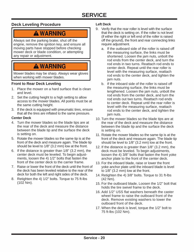
Deck Leveling Procedure
Always set the parking brake, shut off the engine, remove the ignition key, and ensure all moving parts have stopped before checking mower deck or blade condition, or attempting any repair or adjustment.
Mower blades may be sharp. Always wear gloves when working with mower blades.
Front to Rear Deck Leveling1. Place the mower on a hard surface that is clean
and level.2. Set the cutting height to a high setting to allow
access to the mower blades. All points must be at the same cutting height.
3. If the deck is equipped with pneumatic tires, ensure that all the tires are infl ated to the same pressure.
Center Deck4. Turn the mower blades so the blade tips are at
the rear of the deck and measure the distance between the blade tip and the surface the deck is setting on.
5. Rotate the mower blades so the same tip is at the front of the deck and measure again. The blade tip should be level to 1/8” (3.2 mm) low at the front.
6. If the distance is greater than 1/8” (3.2 mm), the center deck must be leveled. To begin adjust-ments, loosen the 4) 1/2” bolts that fasten the front of the center deck to the carrier frame.
7. Raise or lower the front of the deck until the front of the deck has been leveled relative to the rear of the deck for both the left and right sides of the deck.
8. Retighten the 4) 1/2” bolts. Torque to 75 ft-lbs (102 Nm).
Left Deck9. Verify that the rear roller is level with the surface
that the deck is setting on. If the roller is not level (if either the right or left end of the roller is raised off the ground), the front and rear connecting links require adjustment.a. If the outboard side of the roller is raised off
the measuring surface, the links must be shortened. Loosen the jam nuts, unbolt the rod ends from the center deck, and turn the rod ends in two turns. Reattach rod ends to center deck. Repeat until the rear roller is level with the measuring surface, reattach rod ends to the center deck, and tighten the jam nuts.
b. If the inboard side of the roller is raised off the measuring surface, the links must be lengthened. Loosen the jam nuts, unbolt the rod ends from the center deck, and turn the rod ends out two turns. Reattach rod ends to center deck. Repeat until the rear roller is level with the measuring surface, reattach rod ends to the center deck, and tighten the jam nuts.
10. Turn the mower blades so the blade tips are at the rear of the deck and measure the distance between the blade tip and the surface the deck is setting on.
11. Rotate the mower blades so the same tip is at the front of the deck and measure again. The blade tip should be level to 1/8” (3.2 mm) low at the front.
12. If the distance is greater than 1/8” (3.2 mm), the deck must be leveled. To begin adjustments, loosen the 4) 3/8” bolts that fasten the front yoke anchor plate to the front of the center deck.
13. For the inboard blade, raise or lower the front yoke anchor plate until the inboard blade is level to 1/8” (3.2 mm) low at the front.
14. Retighten the 4) 3/8” bolts. Torque to 31 ft-lbs (42 Nm).
15. For the outboard blade, Loosen the 1/2” bolt that holds the tire swivel frame to the deck.
16. Add 1/2” USS fl at washers beneath the caster wheel frame to raise the outboard front of the deck. Remove existing washers to lower the outboard front of the deck.
17. When the deck is level, torque the 1/2” bolt to 75 ft-lbs (102 Nm).

SERVICE
Service - 21
Right Deck18. Verify that the rear roller is level with the surface
that the deck is setting on. If the roller is not level (if either the right or left end of the roller is raised off the ground), the front and rear connecting links require adjustment.a. If the outboard side of the roller is raised off
the measuring surface, the links must be lengthened. Loosen the jam nuts, unbolt the rod ends from the center deck, and turn the rod ends out two turns. Reattach rod ends to center deck. Repeat until the rear roller is level with the measuring surface, reattach rod ends to the center deck, and tighten the jam nuts.
b. If the inboard side of the roller is raised off the measuring surface, the links must be shortened. Loosen the jam nuts, unbolt the rod ends from the center deck, and turn the rod ends in two turns. Reattach rod ends to center deck. Repeat until the rear roller is level with the measuring surface, reattach rod ends to the center deck, and tighten the jam nuts.
19. Turn the mower blades so the blade tips are at the rear of the deck and measure the distance between the blade tip and the surface the deck is setting on.
20. Rotate the mower blades so the same tip is at the front of the deck and measure again. The blade tip should be level to 1/8” (3.2 mm) low at the front.
21. If the distance is greater than 1/8” (3.2 mm), the deck must be leveled. To begin adjustments, loosen the 4) 3/8” bolts that fasten the front yoke anchor plate to the front of the right deck.
22. For the inboard blade, raise or lower the front yoke anchor plate until the inboard blade is level to 1/8” (3.2 mm) low at the front.
23. Retighten the 4) 3/8” bolts. Torque to 31 ft-lbs (42 Nm).
24. For the outboard blade, Loosen the 1/2” bolt that holds the tire swivel frame to the deck.
25. Add 1/2” USS fl at washers beneath the caster wheel frame to raise the outboard front of the deck. Remove existing washers to lower the outboard front of the deck.
26. When the deck is level, torque the 1/2” bolt to 75 ft-lbs (102 Nm).

SERVICE
Service - 22
Lubrication Locations
Always set the parking brake, shut off the engine, remove the ignition key, and ensure all moving parts have stopped before checking mower deck or blade condition, or attempting any repair or adjustment.
Lubrication is required at the following locations. Refer to the maintenance schedule for service intervals.
Some shields and covers removed for clarity.
EE
HH
DD DD
AA
FF DD
DD
FF
CC
AA
Top View of Deck
EE
HH
EE
HH EE
HH
GG GGGGFF FF
Rear View of Deck
Item Description # of LocationsA Drive Shaft 3
B Hitch Arm Pivot 2
C Cylinder End 2
D Spindle 6
E Caster Wheel Pivot 4
F Yoke Pivot 6
G Rear Roller Bearing 6
H Wheel Axle Bearing 4

SERVICE
Service - 23
GearboxCheck gearbox lubricant daily by looking at the sight gauge located on side of gearbox. It should appear half full. Add ISO VG46 oil (Hustler P/N 601621) as necessary. To fi ll, remove the vent plug located on top front of gearbox and add oil until the sight ball fl oats off the bottom.
Vent plugVent plug
Sight GaugeSight Gauge
BB
FF FF
Front View of Deck

SERVICE
Service - 24
Maintenance Schedule
MaintenanceSchedule
Item
#of
Loca
tions
#of
Pum
psAS
NEED
EDDa
ilyAt
50Ho
urs
At10
0Ho
urs
At15
0Ho
urs
At20
0Ho
urs
At25
0Ho
urs
At30
0Ho
urs
At35
0Ho
urs
At40
0Ho
urs
At45
0Ho
urs
At50
0Ho
urs
At55
0Ho
urs
At60
0Ho
urs
At65
0Ho
urs
At70
0Ho
urs
At75
0Ho
urs
At80
0Ho
urs
At85
0Ho
urs
At90
0Ho
urs
At95
0Ho
urs
At10
00Ho
urs
6M
onth
s
Grease & Lubrication: See Lubrication Section
Drive Shaft A 3 1Hitch Arm Pivot B 2 ^Cylinder End C 2 ^
Grease & Lubrication: See Lubrication Section
Cylinder End C 2 ^Spindle D 6 3Caster Wheel Pivot E 4 1Yoke Pivot F 6 ^Rear Roller Bearing ** G 6 1 **Wheel Axle Bearing ** H 4 ^ **
Change Gearbox Oil. Replace w/ ISO VG46 oil.
Check Gearbox Oil Level
Inspect Rear Roller Axle Bolts.
Inspect Belts, Pulleys, Blades, and Blade Retaining Bolts.Inspect Hitch Pivot Bolts.Torque to 170 ft lbs (230 Nm).Inspect Anti-scalp Roller Axle Bolts.Torque to 75 ft lbs (102 Nm).
Inspection
Inspect for Loose, Missing, or Worn Components.
Inspect Safety Decals.
^ Grease Until Fresh Grease is visible
pTorque to 35 ft lbs (47 Nm).Inspect Caster Wheel Axle Bolts and Rear Roller Bracket Bolts. Torque to 31 ft lbs (42 Nm).
** Operation in severe conditions may require more frequent service intervals.

SERVICE
Service - 25
Maintenance Checklist
MaintenanceChecklist
Item
#of
Loca
tions
#of
Pum
psAS
NEED
EDDa
ilyAt
50Ho
urs
At10
0Ho
urs
At15
0Ho
urs
At20
0Ho
urs
At25
0Ho
urs
At30
0Ho
urs
At35
0Ho
urs
At40
0Ho
urs
At45
0Ho
urs
At50
0Ho
urs
At55
0Ho
urs
At60
0Ho
urs
At65
0Ho
urs
At70
0Ho
urs
At75
0Ho
urs
At80
0Ho
urs
At85
0Ho
urs
At90
0Ho
urs
At95
0Ho
urs
At10
00Ho
urs
Year
ly
Grease & Lubrication: See Lubrication Section
Drive Shaft A 3 1Hitch Arm Pivot B 2 ^Cylinder End C 2 ^
Grease & Lubrication: See Lubrication Section
Cylinder End C 2 ^Spindle D 6 3Caster Wheel Pivot E 4 1Yoke Pivot F 6 ^Rear Roller Bearing ** G 6 1 **Wheel Axle Bearing ** H 4 ^ **
Change Gearbox Oil. Replace w/ ISO VG46 oil.
Check Gearbox Oil Level
Inspect Rear Roller Axle Bolts.
Inspect Belts, Pulleys, Blades, and Blade Retaining Bolts.Inspect Hitch Pivot Bolts.Torque to 170 ft lbs (230 Nm).Inspect Anti-scalp Roller Axle Bolts.Torque to 75 ft lbs (102 Nm).
Inspection
Inspect for Loose, Missing, or Worn Components.
Inspect Safety Decals
^ Grease Until Fresh Grease is visible
pTorque to 35 ft lbs (47 Nm).Inspect Caster Wheel Axle Bolts and Rear Roller Bracket Bolts. Torque to 31 ft lbs (42 Nm).
** Operation in severe conditions may require more frequent service intervals.

SPECIFICATIONS
Specifi cations - 26
DimensionsOverall Height . . . . . . . . . . . . . . . . . . . . . . . . . . . . . . . . . 22 inches (55.9 cm)Overall Length . . . . . . . . . . . . . . . . . . . . . . . . . . . . . . . . 52 inches (132.1 cm)Overall Width . . . . . . . . . . . . . . . . . . . . . . . . . . . . . . . . 84 inches (213.5 cm)Transport Width . . . . . . . . . . . . . . . . . . . . . . . . . . . . . . . 82 inches (208.3 cm)Ground Clearance, Transport Mode (ground to center rear roller) . . . . . . . 5-3/4 inches (14.6 cm)Cutting Width . . . . . . . . . . . . . . . . . . . . . . . . . . . . . . . . 83 inches (210.8 cm)Cutting Width, Individual Mowing deck . . . . . . . . . . . . . . . . . . . . 29 inches (73.7 cm)Terrain Contour Angle, Left and Right decks . . . . . . . . . . . . . . . . . . . . +/- 20 degreesWeight . . . . . . . . . . . . . . . . . . . . . . . . . . . . . . . . . . . . .600 pounds (272 kg)Blade Length . . . . . . . . . . . . . . . . . . . . . . . . . . . . . . . . . . . . .15” (38.1 cm)Blades Per Deck . . . . . . . . . . . . . . . . . . . . . . . . . . . . . . . . . . . 2 (1 LH, 1 RH)Cutting Height Range . . . . . . . . . . . . . . . . . . . . 3/4 (19 mm) to 3-1/2 inches (89 mm)Front Gauge Wheels . . . . . . . . . . . . . . . . . . . . . . . . . . . . .Adjustable, Flat FreeRear Rollers . . . . . . . . . . . . . . . . . . . . . . . . . . . . . . . . . . .Full Width, SmoothAnti-scalp Wheels . . . . . . . . . . . . . . . . . . . . . . . . . . . . . . Adjustable, 3 position

Blank Page

Illustrated Parts - 28 Use only original Hustler replacement parts.
PARTSILLUSTRATED DRAWINGDecks & Connector Links
6
6
6
6
66
6 6
2
2
2
2
2
2
2
8
8
8
8
12
10
9
9
9
9
9
1311
11
1
1
1
1
1
1
77
7 7
77
7 7
14
14
1414
14
14
4
4
4
44
4
4
4
4
4
21
21
21
2121
21
5
5 5
5
5 5
55
3
3
33
3
3
3
3
3
33
3
3
33
22
22
20
20
17
17
15
19
18
16
16

PARTS
Illustrated Parts - 29 Use only original Hustler replacement parts.
Decks & Connector LinksREF. PART NO. DESCRIPTION QTY.
1 . . . . . . . . . 29.GF0001 . . . . . . . . . . . . . . . . .GREASE FTG, 1/4 SAE ST . . . . . . . . . . . . . . . . . . . . . . . . . . . . . . . . . . . . . . . . . . . . . . . . . . 62 . . . . . . . . . 91.1016 . . . . . . . . . . . . . . . . . . . .BOLT, HEX 5/8-18 UNF X 2 . . . . . . . . . . . . . . . . . . . . . . . . . . . . . . . . . . . . . . . . . . . . . . . . . . 73 . . . . . . . . . 028118 . . . . . . . . . . . . . . . . . . . .WASHER, FLAT 5/8 SAE . . . . . . . . . . . . . . . . . . . . . . . . . . . . . . . . . . . . . . . . . . . . . . . . . . . 154 . . . . . . . . . 99.A10NFN . . . . . . . . . . . . . . . . .LOCKNUT, NYLON 5/8-18 SAE ZP . . . . . . . . . . . . . . . . . . . . . . . . . . . . . . . . . . . . . . . . . . . 105 . . . . . . . . . 004176 . . . . . . . . . . . . . . . . . . . .WASHER, FLAT 3/8 SAE . . . . . . . . . . . . . . . . . . . . . . . . . . . . . . . . . . . . . . . . . . . . . . . . . . . . 86 . . . . . . . . . 058396 . . . . . . . . . . . . . . . . . . . .BOLT, HEX 3/8-16 UNC X 1 . . . . . . . . . . . . . . . . . . . . . . . . . . . . . . . . . . . . . . . . . . . . . . . . . . 8
7 . . . . . . . . . 016899 . . . . . . . . . . . . . . . . . . . .NUT, SF 3/8-16 USS . . . . . . . . . . . . . . . . . . . . . . . . . . . . . . . . . . . . . . . . . . . . . . . . . . . . . . . 88 . . . . . . . . . 85.B0065 . . . . . . . . . . . . . . . . . . .BUSHING, 5/8ID x 13/16OD x5/8L . . . . . . . . . . . . . . . . . . . . . . . . . . . . . . . . . . . . . . . . . . . . . 49 . . . . . . . . . 07.0601603 . . . . . . . . . . . . . . . . .DECAL, WARNING - DECK SAFETY . . . . . . . . . . . . . . . . . . . . . . . . . . . . . . . . . . . . . . . . . . 510 . . . . . . . . 00.0281 . . . . . . . . . . . . . . . . . . . .DECAL, HEIGHT ADJUST RIGHT . . . . . . . . . . . . . . . . . . . . . . . . . . . . . . . . . . . . . . . . . . . . . 111 . . . . . . . . . 07.0602054 . . . . . . . . . . . . . . . . .DECAL, WARNING - THROWN OBJECT . . . . . . . . . . . . . . . . . . . . . . . . . . . . . . . . . . . . . . . 212 . . . . . . . . 00.0280 . . . . . . . . . . . . . . . . . . . .DECAL, HEIGHT ADJUST, LEFT . . . . . . . . . . . . . . . . . . . . . . . . . . . . . . . . . . . . . . . . . . . . . . 1
13 . . . . . . . . 07.0601625 . . . . . . . . . . . . . . . . .DECAL, READ OWNER’S MANUAL . . . . . . . . . . . . . . . . . . . . . . . . . . . . . . . . . . . . . . . . . . . 114 . . . . . . . . 99.E0011 . . . . . . . . . . . . . . . . . . .NUT, JAM 5/8 SAE . . . . . . . . . . . . . . . . . . . . . . . . . . . . . . . . . . . . . . . . . . . . . . . . . . . . . . . . . 615 . . . . . . . . 62.1353 . . . . . . . . . . . . . . . . . . . .DECK, MOWER WELDMENT CENTER . . . . . . . . . . . . . . . . . . . . . . . . . . . . . . . . . . . . . . . . 116 . . . . . . . . 64.1557 . . . . . . . . . . . . . . . . . . . .PLATE, FRONT YOKE ANCHOR . . . . . . . . . . . . . . . . . . . . . . . . . . . . . . . . . . . . . . . . . . . . . . 217 . . . . . . . . 62.1302 . . . . . . . . . . . . . . . . . . . .FRAME, PIVOT YOKE - MJ840 . . . . . . . . . . . . . . . . . . . . . . . . . . . . . . . . . . . . . . . . . . . . . . . 218 . . . . . . . . 62.1357 . . . . . . . . . . . . . . . . . . . .DECK, MOWER WELDMENT RIGHT . . . . . . . . . . . . . . . . . . . . . . . . . . . . . . . . . . . . . . . . . . 1
19 . . . . . . . . 62.1355 . . . . . . . . . . . . . . . . . . . .DECK, MOWER WELDMENT LEFT . . . . . . . . . . . . . . . . . . . . . . . . . . . . . . . . . . . . . . . . . . . 120 . . . . . . . . 42.0535 . . . . . . . . . . . . . . . . . . . .LINK, DECK CONNECT REAR . . . . . . . . . . . . . . . . . . . . . . . . . . . . . . . . . . . . . . . . . . . . . . . 221 . . . . . . . . 43.010 . . . . . . . . . . . . . . . . . . . . .ROD END, 5/8 SPHERICAL . . . . . . . . . . . . . . . . . . . . . . . . . . . . . . . . . . . . . . . . . . . . . . . . . . 622 . . . . . . . . 42.0534 . . . . . . . . . . . . . . . . . . . .LINK, DECK CONNECT FRONT . . . . . . . . . . . . . . . . . . . . . . . . . . . . . . . . . . . . . . . . . . . . . . 2

PARTS
Illustrated Parts - 30 Use only original Hustler replacement parts.
ILLUSTRATED DRAWINGCarrier Frame
11
11
11
11
11
11
11
11
6 6
6
6
16
16
16
16
3
3
3
3
3
3
3
3
3
3
14
14
14
148
8
8
8
9
9
9
9
7
7
7
7
7
7
7
7
2
2
2
2
2
2
2
2
2
2
15
15
15
15
12
12
12
12
13
13
13
13
4
4
4
4
55
5
5
5
5
5
5
5 5
55
5 5
55
1
1
1
1
1
11
1
1
1
1
1
11
1
1
1
1
1
1
10
10
10
10
10
10
10
10
10
10
10
10
18
18
18
18
19
19
19
19
17
20
20
53.0140
4646
45
47

PARTS
Illustrated Parts - 31 Use only original Hustler replacement parts.
Carrier FrameREF. PART NO. DESCRIPTION QTY.
1 . . . . . . . . . 004168 . . . . . . . . . . . . . . . . . . . .WASHER, FLAT 1/2 SAE . . . . . . . . . . . . . . . . . . . . . . . . . . . . . . . . . . . . . . . . . . . . . . . . . . . 202 . . . . . . . . . 781567 . . . . . . . . . . . . . . . . . . . .LOCKNUT, NYLON 1/2-13 USS . . . . . . . . . . . . . . . . . . . . . . . . . . . . . . . . . . . . . . . . . . . . . . 103 . . . . . . . . . 074252 . . . . . . . . . . . . . . . . . . . .BOLT, HEX 1/2-13 UNC X 1-1/2 . . . . . . . . . . . . . . . . . . . . . . . . . . . . . . . . . . . . . . . . . . . . . . 104 . . . . . . . . . 017137 . . . . . . . . . . . . . . . . . . . .WASHER, FLAT 1/2 USS . . . . . . . . . . . . . . . . . . . . . . . . . . . . . . . . . . . . . . . . . . . . . . . . . . . . 45 . . . . . . . . . 004176 . . . . . . . . . . . . . . . . . . . .WASHER, FLAT 3/8 SAE . . . . . . . . . . . . . . . . . . . . . . . . . . . . . . . . . . . . . . . . . . . . . . . . . . . 166 . . . . . . . . . 058396 . . . . . . . . . . . . . . . . . . . .BOLT, HEX 3/8-16 UNC X 1 . . . . . . . . . . . . . . . . . . . . . . . . . . . . . . . . . . . . . . . . . . . . . . . . . . 4
7 . . . . . . . . . 086660 . . . . . . . . . . . . . . . . . . . .LOCKNUT, NYLON 3/8-16 USS . . . . . . . . . . . . . . . . . . . . . . . . . . . . . . . . . . . . . . . . . . . . . . . 88 . . . . . . . . . 53.0080 . . . . . . . . . . . . . . . . . . . .DUST CAP, BEARING MOWER CASTER . . . . . . . . . . . . . . . . . . . . . . . . . . . . . . . . . . . . . . . 49 . . . . . . . . . 29.GF0001 . . . . . . . . . . . . . . . . .GREASE FTG, 1/4 SAE ST . . . . . . . . . . . . . . . . . . . . . . . . . . . . . . . . . . . . . . . . . . . . . . . . . . 410 . . . . . . . . 99.B0057-2 . . . . . . . . . . . . . . . . .WASHER, MACH 3/4 X 1-1/4 10 GA ZP . . . . . . . . . . . . . . . . . . . . . . . . . . . . . . . . . . . . . . . 1211 . . . . . . . . . 55.0023 . . . . . . . . . . . . . . . . . . . .BEARING, BALL .75 ID X 1.78 OD . . . . . . . . . . . . . . . . . . . . . . . . . . . . . . . . . . . . . . . . . . . . 812 . . . . . . . . 99.B0052 . . . . . . . . . . . . . . . . . . .SHIM, STEEL 3/4 X 1 X .062 . . . . . . . . . . . . . . . . . . . . . . . . . . . . . . . . . . . . . . . . . . . . . . . . . 4
13 . . . . . . . . 04.0013 . . . . . . . . . . . . . . . . . . . .SNAP RING, INT .068 X 1.75 . . . . . . . . . . . . . . . . . . . . . . . . . . . . . . . . . . . . . . . . . . . . . . . . . 414 . . . . . . . . 50.0055 . . . . . . . . . . . . . . . . . . . .TUBE, AXLE-WHEEL LM . . . . . . . . . . . . . . . . . . . . . . . . . . . . . . . . . . . . . . . . . . . . . . . . . . . . 415 . . . . . . . . 99.A12NF . . . . . . . . . . . . . . . . . .LOCKNUT, STOVER 3/4-16 SAE . . . . . . . . . . . . . . . . . . . . . . . . . . . . . . . . . . . . . . . . . . . . . . 416 . . . . . . . . 748913 . . . . . . . . . . . . . . . . . . . .BOLT, HEX 3/8-16 UNC X 5-1/2 . . . . . . . . . . . . . . . . . . . . . . . . . . . . . . . . . . . . . . . . . . . . . . . 417 . . . . . . . . 62.1332 . . . . . . . . . . . . . . . . . . . .FRAME, CARRIER MAIN - EXCEL . . . . . . . . . . . . . . . . . . . . . . . . . . . . . . . . . . . . . . . . . . . . 118 . . . . . . . . 53.0140 . . . . . . . . . . . . . . . . . . . .WHEEL, ASM 9 X 3.5 X4 FLATFREE . . . . . . . . . . . . . . . . . . . . . . . . . . . . . . . . . . . . . . . . . . 4
19 . . . . . . . . 50.0188 . . . . . . . . . . . . . . . . . . . .SPINDLE, TIRE SWIVEL . . . . . . . . . . . . . . . . . . . . . . . . . . . . . . . . . . . . . . . . . . . . . . . . . . . . 420 . . . . . . . . 62.1359 . . . . . . . . . . . . . . . . . . . .FRAME, TIRE SWIVEL . . . . . . . . . . . . . . . . . . . . . . . . . . . . . . . . . . . . . . . . . . . . . . . . . . . . . 245 . . . . . . . . 55.0071 . . . . . . . . . . . . . . . . . . . .BEARING, 3/4 ROLLER 3.25” LONG . . . . . . . . . . . . . . . . . . . . . . . . . . . . . . . . . . . . . . . . . . . 146 . . . . . . . . 55.0072 . . . . . . . . . . . . . . . . . . . .BEARING, RETAINER 3/4” . . . . . . . . . . . . . . . . . . . . . . . . . . . . . . . . . . . . . . . . . . . . . . . . . . 247 . . . . . . . . 29.GF0001 . . . . . . . . . . . . . . . . .GREASE FTG, 1/4 SAE ST . . . . . . . . . . . . . . . . . . . . . . . . . . . . . . . . . . . . . . . . . . . . . . . . . . 1

PARTS
Illustrated Parts - 32 Use only original Hustler replacement parts.
ILLUSTRATED DRAWINGHitch Arms & Hitch Frame Shields
14
1414
14
1414
19
19
11
11
11
11
3
3
18
24
23
16
16
1515
1515
12
12
12
12
20
202
2
4
4
22
22
21
21
13
13
13
13
13
13
13
13
1313
13
13
10
10
10
101
1
17
8
926
25
6
5
5
5
5
7

PARTS
Illustrated Parts - 33 Use only original Hustler replacement parts.
Hitch Arms & Hitch Frame ShieldsREF. PART NO. DESCRIPTION QTY.
1 . . . . . . . . . 028118 . . . . . . . . . . . . . . . . . . . .WASHER, FLAT 5/8 SAE . . . . . . . . . . . . . . . . . . . . . . . . . . . . . . . . . . . . . . . . . . . . . . . . . . . . 22 . . . . . . . . . 99.A10NFN . . . . . . . . . . . . . . . . .LOCKNUT, NYLON 5/8-18 SAE ZP . . . . . . . . . . . . . . . . . . . . . . . . . . . . . . . . . . . . . . . . . . . . 23 . . . . . . . . . 91.1020 . . . . . . . . . . . . . . . . . . . .BOLT, HEX 5/8-18 UNF X 2-1/2 . . . . . . . . . . . . . . . . . . . . . . . . . . . . . . . . . . . . . . . . . . . . . . . 24 . . . . . . . . . 03.0007 . . . . . . . . . . . . . . . . . . . .PIN, BALL 1/2 X 1.8” . . . . . . . . . . . . . . . . . . . . . . . . . . . . . . . . . . . . . . . . . . . . . . . . . . . . . . . 25 . . . . . . . . . 64.1521 . . . . . . . . . . . . . . . . . . . .SPACER, HITCH ARM LATCH . . . . . . . . . . . . . . . . . . . . . . . . . . . . . . . . . . . . . . . . . . . . . . . . 46 . . . . . . . . . 64.1520 . . . . . . . . . . . . . . . . . . . .PLATE, HITCH ARM LATCH LEFT . . . . . . . . . . . . . . . . . . . . . . . . . . . . . . . . . . . . . . . . . . . . 1
7 . . . . . . . . . 64.1525 . . . . . . . . . . . . . . . . . . . .PLATE, HITCH ARM LATCH RIGHT . . . . . . . . . . . . . . . . . . . . . . . . . . . . . . . . . . . . . . . . . . . 18 . . . . . . . . . 60.1086 . . . . . . . . . . . . . . . . . . . .COVER, DECK COVER LEFT . . . . . . . . . . . . . . . . . . . . . . . . . . . . . . . . . . . . . . . . . . . . . . . . 19 . . . . . . . . . 60.1087 . . . . . . . . . . . . . . . . . . . .COVER, DECK CENTER RIGHT . . . . . . . . . . . . . . . . . . . . . . . . . . . . . . . . . . . . . . . . . . . . . . 110 . . . . . . . . 004168 . . . . . . . . . . . . . . . . . . . .WASHER, FLAT 1/2 SAE . . . . . . . . . . . . . . . . . . . . . . . . . . . . . . . . . . . . . . . . . . . . . . . . . . . . 411 . . . . . . . . . 90.0818 . . . . . . . . . . . . . . . . . . . .BOLT, HEX 1/2-13 UNC X 2-1/4 . . . . . . . . . . . . . . . . . . . . . . . . . . . . . . . . . . . . . . . . . . . . . . . 412 . . . . . . . . 703983 . . . . . . . . . . . . . . . . . . . .NUT, SF 1/2-13 USS . . . . . . . . . . . . . . . . . . . . . . . . . . . . . . . . . . . . . . . . . . . . . . . . . . . . . . . 4
13 . . . . . . . . 076547 . . . . . . . . . . . . . . . . . . . .WASHER, FLAT 5/16 SAE . . . . . . . . . . . . . . . . . . . . . . . . . . . . . . . . . . . . . . . . . . . . . . . . . . 1414 . . . . . . . . 034280 . . . . . . . . . . . . . . . . . . . .BOLT, HEX 5/16-18 UNC X 3/4” . . . . . . . . . . . . . . . . . . . . . . . . . . . . . . . . . . . . . . . . . . . . . . . 615 . . . . . . . . 016832 . . . . . . . . . . . . . . . . . . . .NUT, SF 5/16-18 USS . . . . . . . . . . . . . . . . . . . . . . . . . . . . . . . . . . . . . . . . . . . . . . . . . . . . . . 416 . . . . . . . . 29.GF0003 . . . . . . . . . . . . . . . . .GREASE FTG, 1/4 SAE 45 . . . . . . . . . . . . . . . . . . . . . . . . . . . . . . . . . . . . . . . . . . . . . . . . . . 217 . . . . . . . . 60.1076 . . . . . . . . . . . . . . . . . . . .COVER, DECK CENTER REAR . . . . . . . . . . . . . . . . . . . . . . . . . . . . . . . . . . . . . . . . . . . . . . 118 . . . . . . . . 00.0100 . . . . . . . . . . . . . . . . . . . .DECAL, MADE IN USA . . . . . . . . . . . . . . . . . . . . . . . . . . . . . . . . . . . . . . . . . . . . . . . . . . . . . 1
19 . . . . . . . . 90.0512 . . . . . . . . . . . . . . . . . . . .BOLT, HEX 5/16-18 UNC X 1-1/2” . . . . . . . . . . . . . . . . . . . . . . . . . . . . . . . . . . . . . . . . . . . . . 220 . . . . . . . . 058776 . . . . . . . . . . . . . . . . . . . .LOCKNUT, STOVER 5/16-18 USS . . . . . . . . . . . . . . . . . . . . . . . . . . . . . . . . . . . . . . . . . . . . 221 . . . . . . . . 41.0039 . . . . . . . . . . . . . . . . . . . .SPRING, COMP. 9/16 OD X 5/8 . . . . . . . . . . . . . . . . . . . . . . . . . . . . . . . . . . . . . . . . . . . . . . . 222 . . . . . . . . 05.0118 . . . . . . . . . . . . . . . . . . . .BUMPER, RUBBER CYLINDRICAL. . . . . . . . . . . . . . . . . . . . . . . . . . . . . . . . . . . . . . . . . . . . 223 . . . . . . . . 07.0601968 . . . . . . . . . . . . . . . . .DECAL, HIGH PRESSURE FLUID . . . . . . . . . . . . . . . . . . . . . . . . . . . . . . . . . . . . . . . . . . . . 124 . . . . . . . . 07.0601623 . . . . . . . . . . . . . . . . .DECAL, ROTATING DRIVESHAFT . . . . . . . . . . . . . . . . . . . . . . . . . . . . . . . . . . . . . . . . . . . . 1
25 . . . . . . . . 62.1334 . . . . . . . . . . . . . . . . . . . .HITCH, ARM RIGHT . . . . . . . . . . . . . . . . . . . . . . . . . . . . . . . . . . . . . . . . . . . . . . . . . . . . . . . . 126 . . . . . . . . 62.1333 . . . . . . . . . . . . . . . . . . . .HITCH, ARM LEFT . . . . . . . . . . . . . . . . . . . . . . . . . . . . . . . . . . . . . . . . . . . . . . . . . . . . . . . . . 1
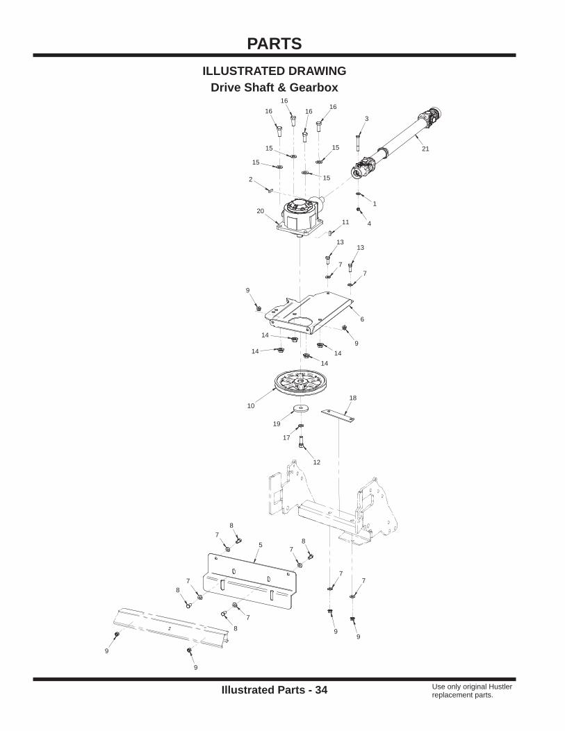
PARTS
Illustrated Parts - 34 Use only original Hustler replacement parts.
ILLUSTRATED DRAWINGDrive Shaft & Gearbox
3
8
8
8
8
1313
1616 16
16
12
21
20
11
2
99
9
9
9
9
14
1414
14
4
10
1
77
77
7
7
7
7
15
1515
15
17
19
5
6
18

PARTS
Illustrated Parts - 35 Use only original Hustler replacement parts.
Drive Shaft & GearboxREF. PART NO. DESCRIPTION QTY.
1 . . . . . . . . . 076547 . . . . . . . . . . . . . . . . . . . .WASHER, FLAT 5/16 SAE . . . . . . . . . . . . . . . . . . . . . . . . . . . . . . . . . . . . . . . . . . . . . . . . . . . 12 . . . . . . . . . 85.K0408 . . . . . . . . . . . . . . . . . . .KEY, 1/4 X 1 . . . . . . . . . . . . . . . . . . . . . . . . . . . . . . . . . . . . . . . . . . . . . . . . . . . . . . . . . . . . . . 13 . . . . . . . . . 90.0520 . . . . . . . . . . . . . . . . . . . .BOLT, HEX 5/16-18 UNC X 2-1/2” . . . . . . . . . . . . . . . . . . . . . . . . . . . . . . . . . . . . . . . . . . . . . 14 . . . . . . . . . 058776 . . . . . . . . . . . . . . . . . . . .LOCKNUT, STOVER 5/16-18 USS . . . . . . . . . . . . . . . . . . . . . . . . . . . . . . . . . . . . . . . . . . . . 15 . . . . . . . . . 60.1077 . . . . . . . . . . . . . . . . . . . .COVER, DECK CENTER FRONT . . . . . . . . . . . . . . . . . . . . . . . . . . . . . . . . . . . . . . . . . . . . . 16 . . . . . . . . . 64.1522 . . . . . . . . . . . . . . . . . . . .MOUNT, GEARBOX . . . . . . . . . . . . . . . . . . . . . . . . . . . . . . . . . . . . . . . . . . . . . . . . . . . . . . . . 1
7 . . . . . . . . . 004176 . . . . . . . . . . . . . . . . . . . .WASHER, FLAT 3/8 SAE . . . . . . . . . . . . . . . . . . . . . . . . . . . . . . . . . . . . . . . . . . . . . . . . . . . . 88 . . . . . . . . . 055822 . . . . . . . . . . . . . . . . . . . .BOLT, HEX 3/8-16 UNC X 3/4 . . . . . . . . . . . . . . . . . . . . . . . . . . . . . . . . . . . . . . . . . . . . . . . . 49 . . . . . . . . . 016899 . . . . . . . . . . . . . . . . . . . .NUT, SF 3/8-16 USS . . . . . . . . . . . . . . . . . . . . . . . . . . . . . . . . . . . . . . . . . . . . . . . . . . . . . . . 610 . . . . . . . . 83.0059 . . . . . . . . . . . . . . . . . . . .PULLEY, 9” X 1” BORE - XJ840 . . . . . . . . . . . . . . . . . . . . . . . . . . . . . . . . . . . . . . . . . . . . . . 111 . . . . . . . . . 85.K0406 . . . . . . . . . . . . . . . . . . .KEY, 1/4 X 3/4 . . . . . . . . . . . . . . . . . . . . . . . . . . . . . . . . . . . . . . . . . . . . . . . . . . . . . . . . . . . . 112 . . . . . . . . 074252 . . . . . . . . . . . . . . . . . . . .BOLT, HEX 1/2-13 UNC X 1-1/2 . . . . . . . . . . . . . . . . . . . . . . . . . . . . . . . . . . . . . . . . . . . . . . . 1
13 . . . . . . . . 058396 . . . . . . . . . . . . . . . . . . . .BOLT, HEX 3/8-16 UNC X 1 . . . . . . . . . . . . . . . . . . . . . . . . . . . . . . . . . . . . . . . . . . . . . . . . . . 214 . . . . . . . . 703983 . . . . . . . . . . . . . . . . . . . .NUT, SF 1/2-13 USS . . . . . . . . . . . . . . . . . . . . . . . . . . . . . . . . . . . . . . . . . . . . . . . . . . . . . . . 415 . . . . . . . . 004168 . . . . . . . . . . . . . . . . . . . .WASHER, FLAT 1/2 SAE . . . . . . . . . . . . . . . . . . . . . . . . . . . . . . . . . . . . . . . . . . . . . . . . . . . . 416 . . . . . . . . 90.0810 . . . . . . . . . . . . . . . . . . . .BOLT, HEX 1/2-13 UNC X 1-1/4 . . . . . . . . . . . . . . . . . . . . . . . . . . . . . . . . . . . . . . . . . . . . . . . 417 . . . . . . . . 96.08 . . . . . . . . . . . . . . . . . . . . . .WASHER, LOCK 1/2 . . . . . . . . . . . . . . . . . . . . . . . . . . . . . . . . . . . . . . . . . . . . . . . . . . . . . . . 118 . . . . . . . . 64.1586 . . . . . . . . . . . . . . . . . . . .SHIM, 12 GA GEARBOX - XJ840 . . . . . . . . . . . . . . . . . . . . . . . . . . . . . . . . . . . . . . . . . . . . . 1
19 . . . . . . . . 99.B0091 . . . . . . . . . . . . . . . . . . .WASHER, .510 ID X 2-1/2 OD 1/4 . . . . . . . . . . . . . . . . . . . . . . . . . . . . . . . . . . . . . . . . . . . . . 120 . . . . . . . . 601712 . . . . . . . . . . . . . . . . . . . .GEARBOX, XJ840 . . . . . . . . . . . . . . . . . . . . . . . . . . . . . . . . . . . . . . . . . . . . . . . . . . . . . . . . . 121 . . . . . . . . 87.0228 . . . . . . . . . . . . . . . . . . . .SHAFT, PTO . . . . . . . . . . . . . . . . . . . . . . . . . . . . . . . . . . . . . . . . . . . . . . . . . . . . . . . . . . . . . . 1

PARTS
Illustrated Parts - 36 Use only original Hustler replacement parts.
ILLUSTRATED DRAWINGDeck Belts
2827
29
19
19
19
13
13
14
13
1414
15
6
6
24
5
5
23
23
20
20
20
20
22
22
22
8
88
8
8
8
8
8
8
8
9
9
11
2
2
12
12
12
12
12
12
12
12
12
21
21
21
16
16
7
7
7
7
3
3
33
33
3
3
3
3
3
3
3
3
33
33
3
3
3
3
3
3
33
3
3
3
3
3
3
3
3
3
3
3
3
3
3
3
1
1
1
1
25
25
26
10
17
18
18
3
4
3
3

PARTS
Illustrated Parts - 37 Use only original Hustler replacement parts.
Deck BeltsREF. PART NO. DESCRIPTION QTY.
1 . . . . . . . . . 004168 . . . . . . . . . . . . . . . . . . . .WASHER, FLAT 1/2 SAE . . . . . . . . . . . . . . . . . . . . . . . . . . . . . . . . . . . . . . . . . . . . . . . . . . . . 42 . . . . . . . . . 781567 . . . . . . . . . . . . . . . . . . . .LOCKNUT, NYLON 1/2-13 USS . . . . . . . . . . . . . . . . . . . . . . . . . . . . . . . . . . . . . . . . . . . . . . . 23 . . . . . . . . . 004176 . . . . . . . . . . . . . . . . . . . .WASHER, FLAT 3/8 SAE . . . . . . . . . . . . . . . . . . . . . . . . . . . . . . . . . . . . . . . . . . . . . . . . . . . 444 . . . . . . . . . 025395 . . . . . . . . . . . . . . . . . . . .BOLT, CARRIAGE 3/8 X 1 . . . . . . . . . . . . . . . . . . . . . . . . . . . . . . . . . . . . . . . . . . . . . . . . . . . 15 . . . . . . . . . 64.1415 . . . . . . . . . . . . . . . . . . . .BUSHING, ANTI-SCALP/IDLER SS . . . . . . . . . . . . . . . . . . . . . . . . . . . . . . . . . . . . . . . . . . . . 26 . . . . . . . . . 008573 . . . . . . . . . . . . . . . . . . . .BOLT, HEX 1/2-13 UNC X 2-1/2 . . . . . . . . . . . . . . . . . . . . . . . . . . . . . . . . . . . . . . . . . . . . . . . 2
7 . . . . . . . . . 704759 . . . . . . . . . . . . . . . . . . . .WASHER, FLAT 7/16 USS . . . . . . . . . . . . . . . . . . . . . . . . . . . . . . . . . . . . . . . . . . . . . . . . . . . 48 . . . . . . . . . 016899 . . . . . . . . . . . . . . . . . . . .NUT, SF 3/8-16 USS . . . . . . . . . . . . . . . . . . . . . . . . . . . . . . . . . . . . . . . . . . . . . . . . . . . . . . 109 . . . . . . . . . 703983 . . . . . . . . . . . . . . . . . . . .NUT, SF 1/2-13 USS . . . . . . . . . . . . . . . . . . . . . . . . . . . . . . . . . . . . . . . . . . . . . . . . . . . . . . . 210 . . . . . . . . 64.1526 . . . . . . . . . . . . . . . . . . . .BRACE, IDLER PULLEY . . . . . . . . . . . . . . . . . . . . . . . . . . . . . . . . . . . . . . . . . . . . . . . . . . . . 111 . . . . . . . . . 99.A06 . . . . . . . . . . . . . . . . . . . . .LOCKNUT, STOVER 3/8-16 USS . . . . . . . . . . . . . . . . . . . . . . . . . . . . . . . . . . . . . . . . . . . . . 112 . . . . . . . . 83.0038 . . . . . . . . . . . . . . . . . . . .PULLEY, V-IDLER 4-1/4 X 3/8 ID . . . . . . . . . . . . . . . . . . . . . . . . . . . . . . . . . . . . . . . . . . . . . . 9
13 . . . . . . . . 760157 . . . . . . . . . . . . . . . . . . . .BOLT, HEX 3/8-16 UNC X 1-3/4 . . . . . . . . . . . . . . . . . . . . . . . . . . . . . . . . . . . . . . . . . . . . . . . 314 . . . . . . . . 016410 . . . . . . . . . . . . . . . . . . . .BOLT, HEX 3/8-16 UNC X 2 . . . . . . . . . . . . . . . . . . . . . . . . . . . . . . . . . . . . . . . . . . . . . . . . . . 315 . . . . . . . . 90.0626 . . . . . . . . . . . . . . . . . . . .BOLT, HEX 3/8-16 UNC X 3-1/4 . . . . . . . . . . . . . . . . . . . . . . . . . . . . . . . . . . . . . . . . . . . . . . . 116 . . . . . . . . 017129 . . . . . . . . . . . . . . . . . . . .WASHER, FLAT 3/8 USS . . . . . . . . . . . . . . . . . . . . . . . . . . . . . . . . . . . . . . . . . . . . . . . . . . . . 217 . . . . . . . . 64.1577 . . . . . . . . . . . . . . . . . . . .BRACKET, IDLER MOUNT . . . . . . . . . . . . . . . . . . . . . . . . . . . . . . . . . . . . . . . . . . . . . . . . . . 118 . . . . . . . . 64.1583 . . . . . . . . . . . . . . . . . . . .BUSHING, BELT TENSIONER . . . . . . . . . . . . . . . . . . . . . . . . . . . . . . . . . . . . . . . . . . . . . . . . 2
19 . . . . . . . . 080655 . . . . . . . . . . . . . . . . . . . .BOLT, HEX 3/8-16 UNC X 1-1/2 . . . . . . . . . . . . . . . . . . . . . . . . . . . . . . . . . . . . . . . . . . . . . . . 320 . . . . . . . . 85.B0088 . . . . . . . . . . . . . . . . . . .BUSHING, 5/8 ID X 3/4 OD X 1/2 . . . . . . . . . . . . . . . . . . . . . . . . . . . . . . . . . . . . . . . . . . . . . 421 . . . . . . . . 41.0084 . . . . . . . . . . . . . . . . . . . .SPRING, TORSION LH 1-3/16 IDX7 . . . . . . . . . . . . . . . . . . . . . . . . . . . . . . . . . . . . . . . . . . . 322 . . . . . . . . 06.0060 . . . . . . . . . . . . . . . . . . . .CAP, VINYL 3/16 ID X 2 LONG . . . . . . . . . . . . . . . . . . . . . . . . . . . . . . . . . . . . . . . . . . . . . . . 323 . . . . . . . . 85.B0027 . . . . . . . . . . . . . . . . . . .BUSHING, 1/2 ID X 5/8 OD X 5/8 . . . . . . . . . . . . . . . . . . . . . . . . . . . . . . . . . . . . . . . . . . . . . 224 . . . . . . . . 016568 . . . . . . . . . . . . . . . . . . . .BOLT, HEX 1/2-13 UNC X 3 . . . . . . . . . . . . . . . . . . . . . . . . . . . . . . . . . . . . . . . . . . . . . . . . . . 1
25 . . . . . . . . 40.0368 . . . . . . . . . . . . . . . . . . . .IDLER ARM, OUTER DECK . . . . . . . . . . . . . . . . . . . . . . . . . . . . . . . . . . . . . . . . . . . . . . . . . . 226 . . . . . . . . 42.0548 . . . . . . . . . . . . . . . . . . . .IDLER ARM, CENTER DECK DRIVE . . . . . . . . . . . . . . . . . . . . . . . . . . . . . . . . . . . . . . . . . . 127 . . . . . . . . 81.AA096 . . . . . . . . . . . . . . . . . .BELT, AA96 . . . . . . . . . . . . . . . . . . . . . . . . . . . . . . . . . . . . . . . . . . . . . . . . . . . . . . . . . . . . . . . 128 . . . . . . . . 81.AA096 . . . . . . . . . . . . . . . . . .BELT, AA96 . . . . . . . . . . . . . . . . . . . . . . . . . . . . . . . . . . . . . . . . . . . . . . . . . . . . . . . . . . . . . . . 129 . . . . . . . . 81.BB064 . . . . . . . . . . . . . . . . . .BELT, BB64 . . . . . . . . . . . . . . . . . . . . . . . . . . . . . . . . . . . . . . . . . . . . . . . . . . . . . . . . . . . . . . 1

PARTS
Illustrated Parts - 38 Use only original Hustler replacement parts.
ILLUSTRATED DRAWINGSpindles
4
4
4
3
3
3
666
6
6
6
66
666
6
6 666
6
6
6
666
6
6
11
11
1110
10
10
15
15
15
15
7
7
7
7
7
7
2
2
2
2 2
22
2 2
2
22
2
2 2
22
2
2
222
22
14
14
14
14
1
1
19
19
19
18
18
18
5
5
5
5
5 5
5
5
5
5
5
5
5
5
5
55
5 5
5
5
5
5 5
12
12
12
12
12
12
9
9
9
9
9
9
8
8
8
8
8
8
16
17
13
87.0229 87.0230
33
31
37
38
36
34
32
30
35
43
4147
48
46
44
40
42
45

PARTS
Illustrated Parts - 39 Use only original Hustler replacement parts.
SpindlesREF. PART NO. DESCRIPTION QTY.
1 . . . . . . . . . 83.0055 . . . . . . . . . . . . . . . . . . . .PULLEY, 2BK50 25MM BORE . . . . . . . . . . . . . . . . . . . . . . . . . . . . . . . . . . . . . . . . . . . . . . . . 22 . . . . . . . . . 99.E0082 . . . . . . . . . . . . . . . . . . .NUT, LOCKING FLANGE 3/8-16 . . . . . . . . . . . . . . . . . . . . . . . . . . . . . . . . . . . . . . . . . . . . . 243 . . . . . . . . . 79.0080 . . . . . . . . . . . . . . . . . . . .BLADE, LH 15 X 2.5 X 1/2 HOLE . . . . . . . . . . . . . . . . . . . . . . . . . . . . . . . . . . . . . . . . . . . . . . 34 . . . . . . . . . 79.0079 . . . . . . . . . . . . . . . . . . . .BLADE, RH 15 X 2.5 X 1/2 HOLE . . . . . . . . . . . . . . . . . . . . . . . . . . . . . . . . . . . . . . . . . . . . . 35 . . . . . . . . . 004176 . . . . . . . . . . . . . . . . . . . .WASHER, FLAT 3/8 SAE . . . . . . . . . . . . . . . . . . . . . . . . . . . . . . . . . . . . . . . . . . . . . . . . . . . 246 . . . . . . . . . 080655 . . . . . . . . . . . . . . . . . . . .BOLT, HEX 3/8-16 UNC X 1-1/2 . . . . . . . . . . . . . . . . . . . . . . . . . . . . . . . . . . . . . . . . . . . . . . 24
7 . . . . . . . . . 99.A12NF . . . . . . . . . . . . . . . . . .LOCKNUT, STOVER 3/4-16 SAE . . . . . . . . . . . . . . . . . . . . . . . . . . . . . . . . . . . . . . . . . . . . . . 68 . . . . . . . . . 64.0688 . . . . . . . . . . . . . . . . . . . .GUARD, SPINDLE/ANTI-STRING . . . . . . . . . . . . . . . . . . . . . . . . . . . . . . . . . . . . . . . . . . . . . 69 . . . . . . . . . 99.B0057-2 . . . . . . . . . . . . . . . . .WASHER, MACH 3/4 X 1-1/4 10 GA ZP . . . . . . . . . . . . . . . . . . . . . . . . . . . . . . . . . . . . . . . . 610 . . . . . . . . 780734 . . . . . . . . . . . . . . . . . . . .BOLT, 1/2-20 SAE X 1 3/4 LH ZP . . . . . . . . . . . . . . . . . . . . . . . . . . . . . . . . . . . . . . . . . . . . . . 311 . . . . . . . . . 753798 . . . . . . . . . . . . . . . . . . . .BOLT, HEX 1/2-20 UNF X 1-3/4 . . . . . . . . . . . . . . . . . . . . . . . . . . . . . . . . . . . . . . . . . . . . . . . 312 . . . . . . . . 004168 . . . . . . . . . . . . . . . . . . . .WASHER, FLAT 1/2 SAE . . . . . . . . . . . . . . . . . . . . . . . . . . . . . . . . . . . . . . . . . . . . . . . . . . . . 6
13 . . . . . . . . 64.1573 . . . . . . . . . . . . . . . . . . . .BRACKET, SPINDLE MOUNT CENTER . . . . . . . . . . . . . . . . . . . . . . . . . . . . . . . . . . . . . . . . 114 . . . . . . . . 83.0050 . . . . . . . . . . . . . . . . . . . .PULLEY, 5-1/8, 25MM STR. BORE . . . . . . . . . . . . . . . . . . . . . . . . . . . . . . . . . . . . . . . . . . . . 415 . . . . . . . . 85.B0080 . . . . . . . . . . . . . . . . . . .BUSHING, 1-1/2 OD, 1 ID . . . . . . . . . . . . . . . . . . . . . . . . . . . . . . . . . . . . . . . . . . . . . . . . . . . 416 . . . . . . . . 64.1569 . . . . . . . . . . . . . . . . . . . .BRACKET, SPINDLE MOUNT RIGHT . . . . . . . . . . . . . . . . . . . . . . . . . . . . . . . . . . . . . . . . . . 117 . . . . . . . . 64.1571 . . . . . . . . . . . . . . . . . . . .BRACKET, SPINDLE MOUNT LEFT . . . . . . . . . . . . . . . . . . . . . . . . . . . . . . . . . . . . . . . . . . . 118 . . . . . . . . 87.0230 . . . . . . . . . . . . . . . . . . . .SPINDLE, ASM LH 25MM AL . . . . . . . . . . . . . . . . . . . . . . . . . . . . . . . . . . . . . . . . . . . . . . . . . 3
19 . . . . . . . . 87.0229 . . . . . . . . . . . . . . . . . . . .SPINDLE, ASM RH 25MM AL . . . . . . . . . . . . . . . . . . . . . . . . . . . . . . . . . . . . . . . . . . . . . . . . 330 . . . . . . . . 87.0209-1 . . . . . . . . . . . . . . . . . .SPINDLE, HOUSING . . . . . . . . . . . . . . . . . . . . . . . . . . . . . . . . . . . . . . . . . . . . . . . . . . . . . . . 131 . . . . . . . . 55.0057 . . . . . . . . . . . . . . . . . . . .BEARING, BALL 25 MM X 62 MM . . . . . . . . . . . . . . . . . . . . . . . . . . . . . . . . . . . . . . . . . . . . . 132 . . . . . . . . 87.0208-2 . . . . . . . . . . . . . . . . . .SHAFT, SPINDLE LH THREAD 25MM . . . . . . . . . . . . . . . . . . . . . . . . . . . . . . . . . . . . . . . . . 133 . . . . . . . . 55.0035 . . . . . . . . . . . . . . . . . . . .BEARING, BALL 25 MM X 62 MM . . . . . . . . . . . . . . . . . . . . . . . . . . . . . . . . . . . . . . . . . . . . . 134 . . . . . . . . 85.B0082 . . . . . . . . . . . . . . . . . . .BUSHING, SPINDLE SHAFT SPACER . . . . . . . . . . . . . . . . . . . . . . . . . . . . . . . . . . . . . . . . . 1
35 . . . . . . . . 87.0210 . . . . . . . . . . . . . . . . . . . .SPINDLE, FLANGE SHIELD . . . . . . . . . . . . . . . . . . . . . . . . . . . . . . . . . . . . . . . . . . . . . . . . . 136 . . . . . . . . 85.W0406 . . . . . . . . . . . . . . . . . .KEY, WOODRUFF 1/4 X 3/4, #806 SAE SIZE . . . . . . . . . . . . . . . . . . . . . . . . . . . . . . . . . . . . 137 . . . . . . . . 29.GF0001 . . . . . . . . . . . . . . . . .GREASE FTG, 1/4 SAE ST . . . . . . . . . . . . . . . . . . . . . . . . . . . . . . . . . . . . . . . . . . . . . . . . . . 138 . . . . . . . . 29.GF0017 . . . . . . . . . . . . . . . . .RELIEF FITTING . . . . . . . . . . . . . . . . . . . . . . . . . . . . . . . . . . . . . . . . . . . . . . . . . . . . . . . . . . 140 . . . . . . . . 87.0209-1 . . . . . . . . . . . . . . . . . .SPINDLE, HOUSING . . . . . . . . . . . . . . . . . . . . . . . . . . . . . . . . . . . . . . . . . . . . . . . . . . . . . . . 141 . . . . . . . . 55.0057 . . . . . . . . . . . . . . . . . . . .BEARING, BALL 25 MM X 62 MM . . . . . . . . . . . . . . . . . . . . . . . . . . . . . . . . . . . . . . . . . . . . . 1
42 . . . . . . . . 87.0209-2 . . . . . . . . . . . . . . . . . .SHAFT, SPINDLE RH THREAD 25MM . . . . . . . . . . . . . . . . . . . . . . . . . . . . . . . . . . . . . . . . . 143 . . . . . . . . 55.0035 . . . . . . . . . . . . . . . . . . . .BEARING, BALL 25 MM X 62 MM . . . . . . . . . . . . . . . . . . . . . . . . . . . . . . . . . . . . . . . . . . . . . 144 . . . . . . . . 85.B0082 . . . . . . . . . . . . . . . . . . .BUSHING, SPINDLE SHAFT SPACER . . . . . . . . . . . . . . . . . . . . . . . . . . . . . . . . . . . . . . . . . 145 . . . . . . . . 87.0210 . . . . . . . . . . . . . . . . . . . .SPINDLE, FLANGE SHIELD . . . . . . . . . . . . . . . . . . . . . . . . . . . . . . . . . . . . . . . . . . . . . . . . . 146 . . . . . . . . 85.W0406 . . . . . . . . . . . . . . . . . .KEY, WOODRUFF 1/4 X 3/4, #806 SAE SIZE . . . . . . . . . . . . . . . . . . . . . . . . . . . . . . . . . . . . 147 . . . . . . . . 29.GF0001 . . . . . . . . . . . . . . . . .GREASE FTG, 1/4 SAE ST . . . . . . . . . . . . . . . . . . . . . . . . . . . . . . . . . . . . . . . . . . . . . . . . . . 1
48 . . . . . . . . 29.GF0017 . . . . . . . . . . . . . . . . .RELIEF FITTING . . . . . . . . . . . . . . . . . . . . . . . . . . . . . . . . . . . . . . . . . . . . . . . . . . . . . . . . . . 1

PARTS
Illustrated Parts - 40 Use only original Hustler replacement parts.
ILLUSTRATED DRAWINGCarrier & Side Deck Shields
11
11
3
30
3
14
14
6
23
22
17
17
27
9
9
19
19
55 5
8
8 77
7
18
1818
18
4
44
21
16
1616
15
15
15
1
1
1
1
1
1
1
1
1
1
1
13
13
13
13
12
12
26
25
24
1020
20
2
2
2
28
29
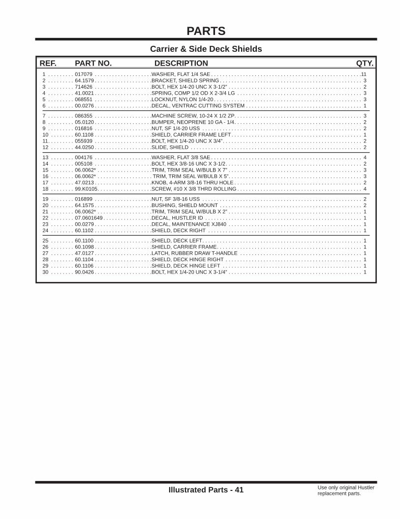
PARTS
Illustrated Parts - 41 Use only original Hustler replacement parts.
Carrier & Side Deck ShieldsREF. PART NO. DESCRIPTION QTY.
1 . . . . . . . . . 017079 . . . . . . . . . . . . . . . . . . . .WASHER, FLAT 1/4 SAE . . . . . . . . . . . . . . . . . . . . . . . . . . . . . . . . . . . . . . . . . . . . . . . . . . . .112 . . . . . . . . . 64.1579 . . . . . . . . . . . . . . . . . . . .BRACKET, SHIELD SPRING . . . . . . . . . . . . . . . . . . . . . . . . . . . . . . . . . . . . . . . . . . . . . . . . . 33 . . . . . . . . . 714626 . . . . . . . . . . . . . . . . . . . .BOLT, HEX 1/4-20 UNC X 3-1/2” . . . . . . . . . . . . . . . . . . . . . . . . . . . . . . . . . . . . . . . . . . . . . . 24 . . . . . . . . . 41.0021 . . . . . . . . . . . . . . . . . . . .SPRING, COMP 1/2 OD X 2-3/4 LG . . . . . . . . . . . . . . . . . . . . . . . . . . . . . . . . . . . . . . . . . . . 35 . . . . . . . . . 068551 . . . . . . . . . . . . . . . . . . . .LOCKNUT, NYLON 1/4-20 . . . . . . . . . . . . . . . . . . . . . . . . . . . . . . . . . . . . . . . . . . . . . . . . . . . 36 . . . . . . . . . 00.0276 . . . . . . . . . . . . . . . . . . . .DECAL, VENTRAC CUTTING SYSTEM . . . . . . . . . . . . . . . . . . . . . . . . . . . . . . . . . . . . . . . . 1
7 . . . . . . . . . 086355 . . . . . . . . . . . . . . . . . . . .MACHINE SCREW, 10-24 X 1/2 ZP . . . . . . . . . . . . . . . . . . . . . . . . . . . . . . . . . . . . . . . . . . . . 38 . . . . . . . . . 05.0120 . . . . . . . . . . . . . . . . . . . .BUMPER, NEOPRENE 10 GA - 1/4 . . . . . . . . . . . . . . . . . . . . . . . . . . . . . . . . . . . . . . . . . . . . 29 . . . . . . . . . 016816 . . . . . . . . . . . . . . . . . . . .NUT, SF 1/4-20 USS . . . . . . . . . . . . . . . . . . . . . . . . . . . . . . . . . . . . . . . . . . . . . . . . . . . . . . . 210 . . . . . . . . 60.1108 . . . . . . . . . . . . . . . . . . . .SHIELD, CARRIER FRAME LEFT . . . . . . . . . . . . . . . . . . . . . . . . . . . . . . . . . . . . . . . . . . . . . 111 . . . . . . . . . 055939 . . . . . . . . . . . . . . . . . . . .BOLT, HEX 1/4-20 UNC X 3/4” . . . . . . . . . . . . . . . . . . . . . . . . . . . . . . . . . . . . . . . . . . . . . . . . 212 . . . . . . . . 44.0250 . . . . . . . . . . . . . . . . . . . .SLIDE, SHIELD . . . . . . . . . . . . . . . . . . . . . . . . . . . . . . . . . . . . . . . . . . . . . . . . . . . . . . . . . . . 2
13 . . . . . . . . 004176 . . . . . . . . . . . . . . . . . . . .WASHER, FLAT 3/8 SAE . . . . . . . . . . . . . . . . . . . . . . . . . . . . . . . . . . . . . . . . . . . . . . . . . . . . 414 . . . . . . . . 005108 . . . . . . . . . . . . . . . . . . . .BOLT, HEX 3/8-16 UNC X 3-1/2 . . . . . . . . . . . . . . . . . . . . . . . . . . . . . . . . . . . . . . . . . . . . . . . 215 . . . . . . . . 06.0062* . . . . . . . . . . . . . . . . . . .TRIM, TRIM SEAL W/BULB X 7” . . . . . . . . . . . . . . . . . . . . . . . . . . . . . . . . . . . . . . . . . . . . . . 316 . . . . . . . . 06.0062* . . . . . . . . . . . . . . . . . . . TRIM, TRIM SEAL W/BULB X 5” . . . . . . . . . . . . . . . . . . . . . . . . . . . . . . . . . . . . . . . . . . . . . . 317 . . . . . . . . 47.0213 . . . . . . . . . . . . . . . . . . . .KNOB, 4-ARM 3/8-16 THRU HOLE . . . . . . . . . . . . . . . . . . . . . . . . . . . . . . . . . . . . . . . . . . . . 218 . . . . . . . . 99.K0105 . . . . . . . . . . . . . . . . . . .SCREW, #10 X 3/8 THRD ROLLING . . . . . . . . . . . . . . . . . . . . . . . . . . . . . . . . . . . . . . . . . . . 4
19 . . . . . . . . 016899 . . . . . . . . . . . . . . . . . . . .NUT, SF 3/8-16 USS . . . . . . . . . . . . . . . . . . . . . . . . . . . . . . . . . . . . . . . . . . . . . . . . . . . . . . . 220 . . . . . . . . 64.1575 . . . . . . . . . . . . . . . . . . . .BUSHING, SHIELD MOUNT . . . . . . . . . . . . . . . . . . . . . . . . . . . . . . . . . . . . . . . . . . . . . . . . . 221 . . . . . . . . 06.0062* . . . . . . . . . . . . . . . . . . .TRIM, TRIM SEAL W/BULB X 2” . . . . . . . . . . . . . . . . . . . . . . . . . . . . . . . . . . . . . . . . . . . . . . 122 . . . . . . . . 07.0601649 . . . . . . . . . . . . . . . . .DECAL, HUSTLER ID . . . . . . . . . . . . . . . . . . . . . . . . . . . . . . . . . . . . . . . . . . . . . . . . . . . . . . 123 . . . . . . . . 00.0279 . . . . . . . . . . . . . . . . . . . .DECAL, MAINTENANCE XJ840 . . . . . . . . . . . . . . . . . . . . . . . . . . . . . . . . . . . . . . . . . . . . . . 124 . . . . . . . . 60.1102 . . . . . . . . . . . . . . . . . . . .SHIELD, DECK RIGHT . . . . . . . . . . . . . . . . . . . . . . . . . . . . . . . . . . . . . . . . . . . . . . . . . . . . . 1
25 . . . . . . . . 60.1100 . . . . . . . . . . . . . . . . . . . .SHIELD, DECK LEFT . . . . . . . . . . . . . . . . . . . . . . . . . . . . . . . . . . . . . . . . . . . . . . . . . . . . . . . 126 . . . . . . . . 60.1098 . . . . . . . . . . . . . . . . . . . .SHIELD, CARRIER FRAME . . . . . . . . . . . . . . . . . . . . . . . . . . . . . . . . . . . . . . . . . . . . . . . . . . 127 . . . . . . . . 47.0127 . . . . . . . . . . . . . . . . . . . .LATCH, RUBBER DRAW T-HANDLE . . . . . . . . . . . . . . . . . . . . . . . . . . . . . . . . . . . . . . . . . . 128 . . . . . . . . 60.1104 . . . . . . . . . . . . . . . . . . . .SHIELD, DECK HINGE RIGHT . . . . . . . . . . . . . . . . . . . . . . . . . . . . . . . . . . . . . . . . . . . . . . . 129 . . . . . . . . 60.1106 . . . . . . . . . . . . . . . . . . . .SHIELD, DECK HINGE LEFT . . . . . . . . . . . . . . . . . . . . . . . . . . . . . . . . . . . . . . . . . . . . . . . . 130 . . . . . . . . 90.0426 . . . . . . . . . . . . . . . . . . . .BOLT, HEX 1/4-20 UNC X 3-1/4” . . . . . . . . . . . . . . . . . . . . . . . . . . . . . . . . . . . . . . . . . . . . . . 1
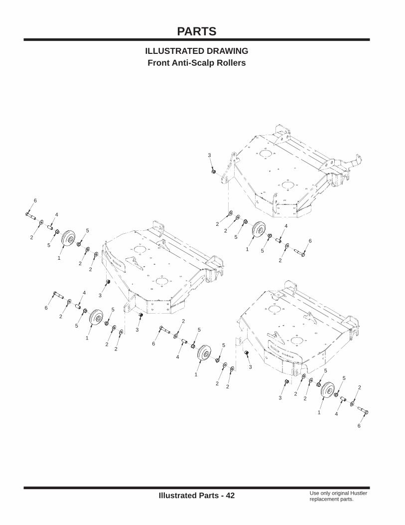
PARTS
Illustrated Parts - 42 Use only original Hustler replacement parts.
ILLUSTRATED DRAWINGFront Anti-Scalp Rollers
6
6
6
6
6
4
4
4
4
4
5
5
5
5
5
5
55
5
5
3
3
3
3
3
1
1
11
1
2
2
2
22
2
2
2
2
2
2
2
2
22

PARTS
Illustrated Parts - 43 Use only original Hustler replacement parts.
Front Anti-Scalp RollersREF. PART NO. DESCRIPTION QTY.
1 . . . . . . . . . 50.0178 . . . . . . . . . . . . . . . . . . . .ROLLER, 4” X 1.625 BLACK UHMW . . . . . . . . . . . . . . . . . . . . . . . . . . . . . . . . . . . . . . . . . . . 52 . . . . . . . . . 704759 . . . . . . . . . . . . . . . . . . . .WASHER, FLAT 7/16 USS . . . . . . . . . . . . . . . . . . . . . . . . . . . . . . . . . . . . . . . . . . . . . . . . . . 153 . . . . . . . . . 781567 . . . . . . . . . . . . . . . . . . . .LOCKNUT, NYLON 1/2-13 USS . . . . . . . . . . . . . . . . . . . . . . . . . . . . . . . . . . . . . . . . . . . . . . . 54 . . . . . . . . . 64.1415 . . . . . . . . . . . . . . . . . . . .BUSHING, ANTI-SCALP/IDLER SS . . . . . . . . . . . . . . . . . . . . . . . . . . . . . . . . . . . . . . . . . . . . 55 . . . . . . . . . 85.B0088 . . . . . . . . . . . . . . . . . . .BUSHING, 5/8 ID X 3/4 OD X 1/2 . . . . . . . . . . . . . . . . . . . . . . . . . . . . . . . . . . . . . . . . . . . . 106 . . . . . . . . . 721910 . . . . . . . . . . . . . . . . . . . .BOLT, HEX 1/2-13 UNC X 2-3/4 . . . . . . . . . . . . . . . . . . . . . . . . . . . . . . . . . . . . . . . . . . . . . . . 5

PARTS
Illustrated Parts - 44 Use only original Hustler replacement parts.
ILLUSTRATED DRAWINGRear Rollers
6
6
6
6
6
6
16
1616
16
16
16
1313
13
13
13
13
88
8
8
8
8
17
17
17
17
17
17
10
10
10
10
1010
11 11
11
11
11
11
9
9
9
9
9
9
9
9
9
9
9
9
1515
1515
15
15
15
15
15
15
15
15
12
12
12
12
12
12
14
14
14
14
14
14
7
7
7
5
5
5
5
5
5
2
3
1
1
1
1
4
4
4

PARTS
Illustrated Parts - 45 Use only original Hustler replacement parts.
Rear RollersREF. PART NO. DESCRIPTION QTY.
1 . . . . . . . . . 64.1581 . . . . . . . . . . . . . . . . . . . .PLATE, ROLLER HEIGHT ADJUST . . . . . . . . . . . . . . . . . . . . . . . . . . . . . . . . . . . . . . . . . . . . 42 . . . . . . . . . 64.1559 . . . . . . . . . . . . . . . . . . . .MOUNT, ROLLER HEIGHT ADJ RIGHT . . . . . . . . . . . . . . . . . . . . . . . . . . . . . . . . . . . . . . . . 13 . . . . . . . . . 64.1561 . . . . . . . . . . . . . . . . . . . .MOUNT, ROLLER HEIGHT ADJ LEFT. . . . . . . . . . . . . . . . . . . . . . . . . . . . . . . . . . . . . . . . . . 14 . . . . . . . . . 80.0372 . . . . . . . . . . . . . . . . . . . .ROLLER, REAR DECK - MJ840 . . . . . . . . . . . . . . . . . . . . . . . . . . . . . . . . . . . . . . . . . . . . . . 35 . . . . . . . . . 53.0135 . . . . . . . . . . . . . . . . . . . .COLLAR, ROLLER END CAP . . . . . . . . . . . . . . . . . . . . . . . . . . . . . . . . . . . . . . . . . . . . . . . . 66 . . . . . . . . . 55.0069 . . . . . . . . . . . . . . . . . . . .BEARING, BALL .625 IN X 40MM . . . . . . . . . . . . . . . . . . . . . . . . . . . . . . . . . . . . . . . . . . . . . 6
7 . . . . . . . . . 42.0537 . . . . . . . . . . . . . . . . . . . .SHAFT, REAR ROLLER . . . . . . . . . . . . . . . . . . . . . . . . . . . . . . . . . . . . . . . . . . . . . . . . . . . . . 38 . . . . . . . . . 29.GF0001 . . . . . . . . . . . . . . . . .GREASE FTG, 1/4 SAE ST . . . . . . . . . . . . . . . . . . . . . . . . . . . . . . . . . . . . . . . . . . . . . . . . . . 69 . . . . . . . . . 739706 . . . . . . . . . . . . . . . . . . . .SET SCREW, 1/4-28 X 3/8” . . . . . . . . . . . . . . . . . . . . . . . . . . . . . . . . . . . . . . . . . . . . . . . . . 1210 . . . . . . . . 26.0028 . . . . . . . . . . . . . . . . . . . .O-RING, 5/8 ID X 3/4 OD X 1/16 . . . . . . . . . . . . . . . . . . . . . . . . . . . . . . . . . . . . . . . . . . . . . . 611 . . . . . . . . . 26.0029 . . . . . . . . . . . . . . . . . . . .O-RING, 1-5/16 X 1-9/16 X 1/8 . . . . . . . . . . . . . . . . . . . . . . . . . . . . . . . . . . . . . . . . . . . . . . . 612 . . . . . . . . 704841 . . . . . . . . . . . . . . . . . . . .WASHER, LOCK 3/8 . . . . . . . . . . . . . . . . . . . . . . . . . . . . . . . . . . . . . . . . . . . . . . . . . . . . . . . 6
13 . . . . . . . . 720268 . . . . . . . . . . . . . . . . . . . .BOLT, 3/8-24 X 1 GRD 8 . . . . . . . . . . . . . . . . . . . . . . . . . . . . . . . . . . . . . . . . . . . . . . . . . . . . 614 . . . . . . . . 05.0112 . . . . . . . . . . . . . . . . . . . .WASHER, NYLON .635ID X1OD X1/4 . . . . . . . . . . . . . . . . . . . . . . . . . . . . . . . . . . . . . . . . . . 615 . . . . . . . . 004176 . . . . . . . . . . . . . . . . . . . .WASHER, FLAT 3/8 SAE . . . . . . . . . . . . . . . . . . . . . . . . . . . . . . . . . . . . . . . . . . . . . . . . . . . 1216 . . . . . . . . 052860 . . . . . . . . . . . . . . . . . . . .BOLT, HEX 3/8-16 UNC X 1-1/4 . . . . . . . . . . . . . . . . . . . . . . . . . . . . . . . . . . . . . . . . . . . . . . . 617 . . . . . . . . 086660 . . . . . . . . . . . . . . . . . . . .LOCKNUT, NYLON 3/8-16 USS . . . . . . . . . . . . . . . . . . . . . . . . . . . . . . . . . . . . . . . . . . . . . . . 6

PARTS
Illustrated Parts - 46 Use only original Hustler replacement parts.
ILLUSTRATED DRAWINGDischarge Defl ectors & Rear Belting
6
6
6
6
6
6
6
6
5
5
5
5
5
5
55
55
5
5
5
55
5
7
7
7
7
7
7
7
7
7
3
3
3
33
3
33
3
3
33
3
3
3
4 4
4
44
44
4
44
4
4
44
4
4
1
1
1
8
8
9
2
2
2

PARTS
Illustrated Parts - 47 Use only original Hustler replacement parts.
Discharge Defl ectors & Rear BeltingREF. PART NO. DESCRIPTION QTY.
1 . . . . . . . . . 44.0251 . . . . . . . . . . . . . . . . . . . .BELTING, REAR DISCHARGE . . . . . . . . . . . . . . . . . . . . . . . . . . . . . . . . . . . . . . . . . . . . . . . 32 . . . . . . . . . 64.1422 . . . . . . . . . . . . . . . . . . . .CLAMP, REAR BELTING . . . . . . . . . . . . . . . . . . . . . . . . . . . . . . . . . . . . . . . . . . . . . . . . . . . . 33 . . . . . . . . . 99.A04 . . . . . . . . . . . . . . . . . . . . .LOCKNUT, STOVER 1/4-20 USS . . . . . . . . . . . . . . . . . . . . . . . . . . . . . . . . . . . . . . . . . . . . 154 . . . . . . . . . 017079 . . . . . . . . . . . . . . . . . . . .WASHER, FLAT 1/4 SAE . . . . . . . . . . . . . . . . . . . . . . . . . . . . . . . . . . . . . . . . . . . . . . . . . . . 165 . . . . . . . . . 055939 . . . . . . . . . . . . . . . . . . . .BOLT, HEX 1/4-20 UNC X 3/4” . . . . . . . . . . . . . . . . . . . . . . . . . . . . . . . . . . . . . . . . . . . . . . . 166 . . . . . . . . . 023143 . . . . . . . . . . . . . . . . . . . .BOLT, SF 1/4-20 X 1/2 . . . . . . . . . . . . . . . . . . . . . . . . . . . . . . . . . . . . . . . . . . . . . . . . . . . . . . 8
7 . . . . . . . . . 016816 . . . . . . . . . . . . . . . . . . . .NUT, SF 1/4-20 USS . . . . . . . . . . . . . . . . . . . . . . . . . . . . . . . . . . . . . . . . . . . . . . . . . . . . . . . 98 . . . . . . . . . 60.1110 . . . . . . . . . . . . . . . . . . . .DEFLECTOR, DECK DISCHARGE R/C . . . . . . . . . . . . . . . . . . . . . . . . . . . . . . . . . . . . . . . . 29 . . . . . . . . . 60.1112 . . . . . . . . . . . . . . . . . . . .DEFLECTOR, DECK DISCHARGE LEFT . . . . . . . . . . . . . . . . . . . . . . . . . . . . . . . . . . . . . . . 1

PARTS
Illustrated Parts - 48 Use only original Hustler replacement parts.
ILLUSTRATED DRAWINGDeck Wing Lift Arms
6
6
12
12
12
12
12
12
12
12
4
4
4
4
9
9
14
14
14
14
10
10
10
10
16
16
7
7
11
11
11
11
11
11
11
11
11
11
11
11
11
11
11
11
33
3
3
3
3
3
3
8
8
8
8
15
15
5
5
13
13
13
13
13
13
13
13
2
2
22
1
1
1
11
1
19
19
20
20
21
18
17
17

PARTS
Illustrated Parts - 49 Use only original Hustler replacement parts.
Deck Wing Lift ArmsREF. PART NO. DESCRIPTION QTY.
1 . . . . . . . . . 004168 . . . . . . . . . . . . . . . . . . . .WASHER, FLAT 1/2 SAE . . . . . . . . . . . . . . . . . . . . . . . . . . . . . . . . . . . . . . . . . . . . . . . . . . . . 62 . . . . . . . . . 004176 . . . . . . . . . . . . . . . . . . . .WASHER, FLAT 3/8 SAE . . . . . . . . . . . . . . . . . . . . . . . . . . . . . . . . . . . . . . . . . . . . . . . . . . . . 43 . . . . . . . . . 016899 . . . . . . . . . . . . . . . . . . . .NUT, SF 3/8-16 USS . . . . . . . . . . . . . . . . . . . . . . . . . . . . . . . . . . . . . . . . . . . . . . . . . . . . . . . 84 . . . . . . . . . 052860 . . . . . . . . . . . . . . . . . . . .BOLT, HEX 3/8-16 UNC X 1-1/4 . . . . . . . . . . . . . . . . . . . . . . . . . . . . . . . . . . . . . . . . . . . . . . . 45 . . . . . . . . . 017079 . . . . . . . . . . . . . . . . . . . .WASHER, FLAT 1/4 SAE . . . . . . . . . . . . . . . . . . . . . . . . . . . . . . . . . . . . . . . . . . . . . . . . . . . . 26 . . . . . . . . . 055939 . . . . . . . . . . . . . . . . . . . .BOLT, HEX 1/4-20 UNC X 3/4” . . . . . . . . . . . . . . . . . . . . . . . . . . . . . . . . . . . . . . . . . . . . . . . . 2
7 . . . . . . . . . 016816 . . . . . . . . . . . . . . . . . . . .NUT, SF 1/4-20 USS . . . . . . . . . . . . . . . . . . . . . . . . . . . . . . . . . . . . . . . . . . . . . . . . . . . . . . . 28 . . . . . . . . . 703983 . . . . . . . . . . . . . . . . . . . .NUT, SF 1/2-13 USS . . . . . . . . . . . . . . . . . . . . . . . . . . . . . . . . . . . . . . . . . . . . . . . . . . . . . . . 49 . . . . . . . . . 078949 . . . . . . . . . . . . . . . . . . . .BOLT, HEX 1/2-13 UNC X 2 . . . . . . . . . . . . . . . . . . . . . . . . . . . . . . . . . . . . . . . . . . . . . . . . . . 210 . . . . . . . . 45.0047 . . . . . . . . . . . . . . . . . . . .CABLE, 1/8 X 12 SS W/3/8 LOOPS . . . . . . . . . . . . . . . . . . . . . . . . . . . . . . . . . . . . . . . . . . . . 411 . . . . . . . . . 016832 . . . . . . . . . . . . . . . . . . . .NUT, SF 5/16-18 USS . . . . . . . . . . . . . . . . . . . . . . . . . . . . . . . . . . . . . . . . . . . . . . . . . . . . . 1612 . . . . . . . . 036236 . . . . . . . . . . . . . . . . . . . .BOLT, HEX 5/16-18 UNC X 1” . . . . . . . . . . . . . . . . . . . . . . . . . . . . . . . . . . . . . . . . . . . . . . . . 8
13 . . . . . . . . 076547 . . . . . . . . . . . . . . . . . . . .WASHER, FLAT 5/16 SAE . . . . . . . . . . . . . . . . . . . . . . . . . . . . . . . . . . . . . . . . . . . . . . . . . . . 814 . . . . . . . . 85.B0027 . . . . . . . . . . . . . . . . . . .BUSHING, 1/2 ID X 5/8 OD X 5/8 . . . . . . . . . . . . . . . . . . . . . . . . . . . . . . . . . . . . . . . . . . . . . 415 . . . . . . . . 41.0084 . . . . . . . . . . . . . . . . . . . .SPRING, TORSION LH 1-3/16 IDX7 . . . . . . . . . . . . . . . . . . . . . . . . . . . . . . . . . . . . . . . . . . . 216 . . . . . . . . 07.0602987 . . . . . . . . . . . . . . . . .DECAL, WARNING - PINCH POINT . . . . . . . . . . . . . . . . . . . . . . . . . . . . . . . . . . . . . . . . . . . 217 . . . . . . . . 64.1567 . . . . . . . . . . . . . . . . . . . .LIMITER, DECK HINGE UPPER . . . . . . . . . . . . . . . . . . . . . . . . . . . . . . . . . . . . . . . . . . . . . . 218 . . . . . . . . 64.1565 . . . . . . . . . . . . . . . . . . . .LIMITER, DECK HINGE LOWER L . . . . . . . . . . . . . . . . . . . . . . . . . . . . . . . . . . . . . . . . . . . . 1
19 . . . . . . . . 62.1361 . . . . . . . . . . . . . . . . . . . .LIFT ARM, OUTSIDE DECK WING . . . . . . . . . . . . . . . . . . . . . . . . . . . . . . . . . . . . . . . . . . . . 220 . . . . . . . . 64.1563 . . . . . . . . . . . . . . . . . . . .PIN, LIFT ARM PIVOT . . . . . . . . . . . . . . . . . . . . . . . . . . . . . . . . . . . . . . . . . . . . . . . . . . . . . . 221 . . . . . . . . 64.1565 . . . . . . . . . . . . . . . . . . . .LIMITER, DECK HINGE LOWER (Serial # 930438-1102**** & earlier) . . . . . . . . . . . . . . . . . 121 . . . . . . . . 64.1659 . . . . . . . . . . . . . . . . . . . .LIMITER, DECK HINGE LOWER R (Serial # 930438-1103**** & later) . . . . . . . . . . . . . . . . . 1

PARTS
Illustrated Parts - 50 Use only original Hustler replacement parts.
ILLUSTRATED DRAWINGDeck Wing Lift Arm Hydraulics
11
7
7
6
5
17
17
12
14
99
8
8
1010
21
22
16
16
13
1
3
3
3
19
19
4
4
15
2
2
2
2
23
18
20
24
23.0158
40
40

PARTS
Illustrated Parts - 51 Use only original Hustler replacement parts.
Deck Wing Lift Arm HydraulicsREF. PART NO. DESCRIPTION QTY.
1 . . . . . . . . . 781567 . . . . . . . . . . . . . . . . . . . .LOCKNUT, NYLON 1/2-13 USS . . . . . . . . . . . . . . . . . . . . . . . . . . . . . . . . . . . . . . . . . . . . . . . 12 . . . . . . . . . 028118 . . . . . . . . . . . . . . . . . . . .WASHER, FLAT 5/8 SAE . . . . . . . . . . . . . . . . . . . . . . . . . . . . . . . . . . . . . . . . . . . . . . . . . . . . 43 . . . . . . . . . 99.A10NFN . . . . . . . . . . . . . . . . .LOCKNUT, NYLON 5/8-18 SAE ZP . . . . . . . . . . . . . . . . . . . . . . . . . . . . . . . . . . . . . . . . . . . . 34 . . . . . . . . . 704759 . . . . . . . . . . . . . . . . . . . .WASHER, FLAT 7/16 USS . . . . . . . . . . . . . . . . . . . . . . . . . . . . . . . . . . . . . . . . . . . . . . . . . . . 25 . . . . . . . . . 64.1427 . . . . . . . . . . . . . . . . . . . .BUSHING, IDLER ARM PIVOT - SS . . . . . . . . . . . . . . . . . . . . . . . . . . . . . . . . . . . . . . . . . . . 16 . . . . . . . . . 91.1024 . . . . . . . . . . . . . . . . . . . .BOLT, 5/8-18 SAE X 3 . . . . . . . . . . . . . . . . . . . . . . . . . . . . . . . . . . . . . . . . . . . . . . . . . . . . . . 1
7 . . . . . . . . . 774794 . . . . . . . . . . . . . . . . . . . .BOLT, HEX 5/8-18 UNF X 2-1/4 . . . . . . . . . . . . . . . . . . . . . . . . . . . . . . . . . . . . . . . . . . . . . . . 28 . . . . . . . . . 25.6801-06-06 . . . . . . . . . . . . . . .FITTING, 90 ME 3/8 X 3/8 . . . . . . . . . . . . . . . . . . . . . . . . . . . . . . . . . . . . . . . . . . . . . . . . . . . 29 . . . . . . . . . 25.2501-06-06 . . . . . . . . . . . . . . .FITTING, 90 ME 3/8 X 3/8 . . . . . . . . . . . . . . . . . . . . . . . . . . . . . . . . . . . . . . . . . . . . . . . . . . . 210 . . . . . . . . 23.0157 . . . . . . . . . . . . . . . . . . . .COUPLER, QUICK MALE 3/8 . . . . . . . . . . . . . . . . . . . . . . . . . . . . . . . . . . . . . . . . . . . . . . . . 211 . . . . . . . . . 064345 . . . . . . . . . . . . . . . . . . . .BOLT, HEX 5/16-18 UNC X 2” . . . . . . . . . . . . . . . . . . . . . . . . . . . . . . . . . . . . . . . . . . . . . . . . 112 . . . . . . . . 44.0229 . . . . . . . . . . . . . . . . . . . .COVER PLATE, 2D GROUP . . . . . . . . . . . . . . . . . . . . . . . . . . . . . . . . . . . . . . . . . . . . . . . . . 1
13 . . . . . . . . 058776 . . . . . . . . . . . . . . . . . . . .LOCKNUT, STOVER 5/16-18 USS . . . . . . . . . . . . . . . . . . . . . . . . . . . . . . . . . . . . . . . . . . . . 114 . . . . . . . . 44.0256 . . . . . . . . . . . . . . . . . . . .CLAMP, HYD HOSE 12.7MM ID GRN . . . . . . . . . . . . . . . . . . . . . . . . . . . . . . . . . . . . . . . . . . 115 . . . . . . . . 076547 . . . . . . . . . . . . . . . . . . . .WASHER, FLAT 5/16 SAE . . . . . . . . . . . . . . . . . . . . . . . . . . . . . . . . . . . . . . . . . . . . . . . . . . . 116 . . . . . . . . 99.E0011 . . . . . . . . . . . . . . . . . . .NUT, JAM 5/8 SAE . . . . . . . . . . . . . . . . . . . . . . . . . . . . . . . . . . . . . . . . . . . . . . . . . . . . . . . . . 217 . . . . . . . . 85.B0065 . . . . . . . . . . . . . . . . . . .BUSHING, 5/8ID x 13/16OD x5/8L . . . . . . . . . . . . . . . . . . . . . . . . . . . . . . . . . . . . . . . . . . . . . 218 . . . . . . . . 42.0531 . . . . . . . . . . . . . . . . . . . .LINK, LIFT ARM RIGHT DECK . . . . . . . . . . . . . . . . . . . . . . . . . . . . . . . . . . . . . . . . . . . . . . . 1
19 . . . . . . . . 43.010 . . . . . . . . . . . . . . . . . . . . .ROD END, 5/8 SPHERICAL . . . . . . . . . . . . . . . . . . . . . . . . . . . . . . . . . . . . . . . . . . . . . . . . . . 220 . . . . . . . . 42.0532 . . . . . . . . . . . . . . . . . . . .PIVOT, LIFT LINK MJ . . . . . . . . . . . . . . . . . . . . . . . . . . . . . . . . . . . . . . . . . . . . . . . . . . . . . . . 121 . . . . . . . . 20.0122 . . . . . . . . . . . . . . . . . . . .HOSE, 1/4 X 43.00 SAE 100R17AR . . . . . . . . . . . . . . . . . . . . . . . . . . . . . . . . . . . . . . . . . . . 122 . . . . . . . . 20.0136 . . . . . . . . . . . . . . . . . . . .HOSE, 1/4X36.00 SAE 100R17AR . . . . . . . . . . . . . . . . . . . . . . . . . . . . . . . . . . . . . . . . . . . . 123 . . . . . . . . 42.0530 . . . . . . . . . . . . . . . . . . . .LINK, LIFT ARM LEFT DECK . . . . . . . . . . . . . . . . . . . . . . . . . . . . . . . . . . . . . . . . . . . . . . . . . 124 . . . . . . . . 23.0158 . . . . . . . . . . . . . . . . . . . .CYLINDER, 1-1/2” X 5” . . . . . . . . . . . . . . . . . . . . . . . . . . . . . . . . . . . . . . . . . . . . . . . . . . . . . 1
40 . . . . . . . . 29.GF0001 . . . . . . . . . . . . . . . . .GREASE FTG, 1/4 SAE ST . . . . . . . . . . . . . . . . . . . . . . . . . . . . . . . . . . . . . . . . . . . . . . . . . . 2

PARTS
Illustrated Parts - 52 Use only original Hustler replacement parts.
ILLUSTRATED DRAWINGMulch Kit
9
9
7
7
7
7
7
7
7
7
7
7 7
7
77
7
7
7
7
7
7
7
7
8
8
88
8
8
8
8
8
8
8
8
8
8
8
88
88
88
8
88
5
61
2 4
3

PARTS
Illustrated Parts - 53 Use only original Hustler replacement parts.
Mulch KitREF. PART NO. DESCRIPTION QTY.
1 . . . . . . . . . 64.1418 . . . . . . . . . . . . . . . . . . . .RING, RIGHT MULCH - CENTER DECK . . . . . . . . . . . . . . . . . . . . . . . . . . . . . . . . . . . . . . . . 12 . . . . . . . . . 64.1419 . . . . . . . . . . . . . . . . . . . .RING, LEFT MULCH - CENTER DECK . . . . . . . . . . . . . . . . . . . . . . . . . . . . . . . . . . . . . . . . . 13 . . . . . . . . . 64.1421 . . . . . . . . . . . . . . . . . . . .RING, LEFT MULCH - LEFT DECK . . . . . . . . . . . . . . . . . . . . . . . . . . . . . . . . . . . . . . . . . . . . 14 . . . . . . . . . 64.1420 . . . . . . . . . . . . . . . . . . . .RING, RIGHT MULCH - LEFT DECK . . . . . . . . . . . . . . . . . . . . . . . . . . . . . . . . . . . . . . . . . . . 15 . . . . . . . . . 64.1416 . . . . . . . . . . . . . . . . . . . .RING, RIGHT MULCH - RIGHT DECK . . . . . . . . . . . . . . . . . . . . . . . . . . . . . . . . . . . . . . . . . 16 . . . . . . . . . 64.1417 . . . . . . . . . . . . . . . . . . . .RING, LEFT MULCH - RIGHT DECK . . . . . . . . . . . . . . . . . . . . . . . . . . . . . . . . . . . . . . . . . . . 1
7 . . . . . . . . . 99.SF0506 . . . . . . . . . . . . . . . . . .BOLT, SF 5/16-18 USS X 3/4 . . . . . . . . . . . . . . . . . . . . . . . . . . . . . . . . . . . . . . . . . . . . . . . . 228 . . . . . . . . . 016832 . . . . . . . . . . . . . . . . . . . .NUT, SF 5/16-18 USS . . . . . . . . . . . . . . . . . . . . . . . . . . . . . . . . . . . . . . . . . . . . . . . . . . . . . 249 . . . . . . . . . 99.SF0504 . . . . . . . . . . . . . . . . . .BOLT, SF 5/16-18 X 1/2 . . . . . . . . . . . . . . . . . . . . . . . . . . . . . . . . . . . . . . . . . . . . . . . . . . . . . 2

Warranty - 54
WARRANTYHUSTLER FLEX DECK
TWO YEAR (1500 HOURS) LIMITED WARRANTY FOR DECKWHAT IS COVERED BY THIS WARRANTYHustler Turf Equipment, makes the following warranty to the original purchaser only:
a. First and Second Year: Hustler Turf Equipment Flex Decks are war-ranted for two (2) years or 1500 hours of use, whichever comes fi rst, from date of delivery on all materials and workmanship.If the Purchaser discovers, within this warranty period, a defect in materials or workmanship:
• He must promptly notify Hustler Turf Equipment, or an authorized dealer, in writing of the defect. In no event shall such notifi cation be received by Hustler Turf Equipment, or an authorized dealer later than twenty-fi ve (25) months from date of delivery.
• Within a reasonable time after such notifi cation, Hustler Turf Equipment will correct any defect in material or workmanship on the Hustler Turf Equipment, by repairing or replacing part(s) with either new or used replacement parts.
• Such repair, including parts and labor, shall be at the expense of Hustler Turf Equipment, and,
b. Rental Units (90 days): Within 90 days of date of delivery, Hustler Turf Equipment provides a limited warranty on all materials and workmanship for units used for rental purposes.If the Purchaser discovers, within this warranty period, a defect in materials or workmanship:
• He must promptly notify Hustler Turf Equipment, or an authorized dealer, in writing of the defect. In no event shall such notifi cation be received by Hustler Turf Equipment, or an authorized dealer later than 120 days from date of delivery.
• Within a reasonable time after such notifi cation, Hustler Turf Equipment will correct any defect in material or workmanship on the Hustler Turf Equipment, by repairing or replacing part(s) with either new or used replacement parts.
• Such repair, including parts and labor, shall be at the expense of Hustler Turf Equipment, and,
WHO MUST PERFORM THE WARRANTY SERVICEAll warranty service will be performed by dealers authorized by Hustler Turf Equipment. Service calls and/or transportation expense of the product to and from the authorized dealer for warranty work, will be paid by the owner of the product. For warranty service, you can contact an authorized dealer or write Hustler Turf Equipment, 200 South Ridge Road, Hesston, Kansas 67062, or call 1-620-327-4911.
WHAT IS NOT COVERED BY THIS WARRANTYHustler Turf Equipment does not warranty:
• Some product, components, or parts not manufactured by Hustler Turf Equipment
• Repairs made by unauthorized persons• Damage caused by the use of Hustler Turf Equipment for pur-
poses other than those for which it was designed• Damages caused by disasters such as fi re, fl ood, wind, and lightning.• Damages caused by neglect, abuse, abnormal use, improper or
unreasonable use, accident, negligence, or misuse• Repairs or replacement resulting from the use of unauthorized
parts, accessories, or attachments• Repairs or replacement as the result of any alterations or modifi ca-
tions, in the determination of Hustler Turf Equipment, which adverse-ly affects the operation, performance, or durability of the equipment
• Hustler Turf Equipment which has the serial number removed or made illegible
• Depreciation or damage caused by normal wear, lack of reason-able and proper maintenance, failure to follow the product’s owner’s manual operating, maintenance, and adjustment instructions or other operational instructions provided by Hustler Turf Equipment.
• Normal maintenance parts and service including, but not limited to, lubricants, belts, blades, blade sharpening, bearings.
DISCLAIMER OF WARRANTYThe foregoing warranties are in lieu of all other warranties, expressed or implied, including but not limited to the implied warranties of mer-chantability and fi tness for a particular purpose. However, if the Hustler Turf Equipment is purchased as a consumer product, any implied war-ranty of merchantability and fi tness for a particular purpose is limited to the duration of this limited warranty. Some states do not allow limita-tions on how long an implied warranty lasts, so the above limitation may not apply to you. This warranty gives you specifi c legal rights, and you may also have other rights which vary from state to state.
LIMITATION OF REMEDIESIn no case shall Hustler Turf Equipment be liable for any special, inciden-tal, or consequential damages based upon breach of warranty, breach of contract, negligence, strict liability in tort, or any other legal theory.Such damages include, but are not limited to:
• Loss of profi ts• Loss of savings or revenue• Loss of use of Hustler Turf Equipment or any associated equipment• Cost of capital• Cost of any substitute equipment, facilities, services, or downtime• The claims of third parties including customers, and injury to property.
Some states do not allow the exclusion or limitation of incidental or conse-quential damages, so the above limitation or exclusion may not apply to you.
TIME LIMITAny action for breach of warranty must be commenced within twenty-fi ve (25) months following delivery of the goods in a non-rental applica-tion. Any action for breach of warranty must be commenced within 120 days following delivery of the goods in a rental application.
NO OTHER WARRANTIESUnless modifi ed in writing, signed by both parties, and approved by the President of Hustler Turf Equipment, this agreement is understood to be the complete and exclusive agreement between the parties, supersed-ing all prior agreements, oral or written, and all other communications between the parties relating to the subject matter of this agreement. No employee of Hustler Turf Equipment, or any other party, is authorized to make any warranty in addition to those made in this agreement.
ALLOCATION OF RISKSThis agreement allocates the risks of product failure between Hustler Turf Equipment and the purchaser. This allocation is recognized by both parties and is refl ected in the price of the goods.
OWNER’S RESPONSIBILITYYou must maintain your Hustler Turf Equipment product following the main-tenance procedures described in your owner’s manual. Such routine main-tenance, whether performed by a dealer or by you, is at your expense. This machine like any other powered equipment is potentially dangerous unless properly operated. Any operator must be cautious and keep safety in mind at all times. Any operator, prior to using the Hustler Turf Equipment, should thoroughly familiarize himself with the owner’s manual regarding operation and safety of the machine, as well as all safety warnings on the machine itself.
WARRANTY REGISTRATION1. Dealers must register the unit online at www.Hustlerdealer.com or
by fi lling out the Warranty registration form provided in the owner’s packet. If using the Warranty registration form, it MUST be complet-ed and signed by the authorized dealer and original purchaser.
2. For validation, the completed Warranty registration form MUST be forwarded to Hustler Turf Equipment, within ten (10) days following date of purchase.
3. The date of purchase constitutes delivery.