Embed Size (px)
Citation preview
High Brightness, HVDC, Photoemission Electron Gun
Development at Cornell
Charlie SinclairCornell University
9/3/2010 1FLS 2010
9/3/2010 2
Outline• 750 kV Gun• 750 kV, 100mA HVPS• GaAs Photocathode• 20W, 520 nm, 1.3 GHz Laser • Photocathode and Gun Development
Laboratory• Summary
FLS 2010
9/3/2010 3
HVDC Gun Performance Goals• Operation at or above 500 kV• Maximum voltage of 750 kV• 100 mA average current, in a 1.3 GHz train
of 77 pC bunches, 20-30 ps duration, • εn < 0.3 µm, with nominal “tophat”
transverse and longitudinal profiles• Cathode operating lifetime 100 h at 100 mA
FLS 2010
9/3/2010 4
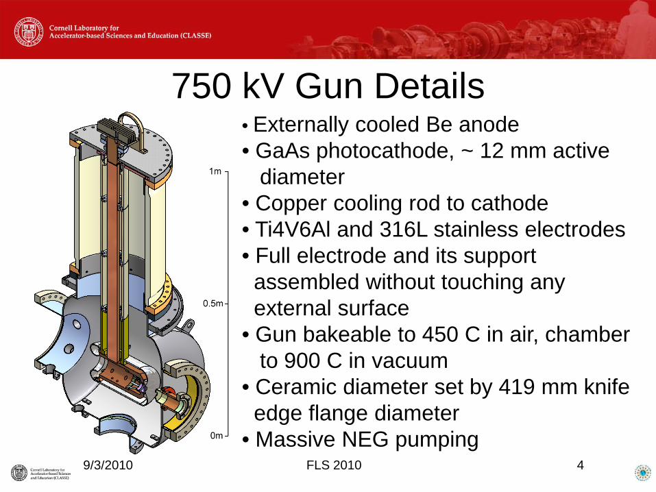
750 kV Gun Details• Externally cooled Be anode• GaAs photocathode, ~ 12 mm active
diameter• Copper cooling rod to cathode• Ti4V6Al and 316L stainless electrodes • Full electrode and its supportassembled without touching anyexternal surface
• Gun bakeable to 450 C in air, chamberto 900 C in vacuum
• Ceramic diameter set by 419 mm knife edge flange diameter
• Massive NEG pumping FLS 2010
9/3/2010 5
Gun Operation to date• First beam in September 2006• Operated standalone for cathode and beam
studies for many months• Operation to date limited to ~ 250 kV by
ceramic problems (punch through and braze failures)
• Operation for a year in full injector test• Gun operation and cathode exchanges are
trouble free and routineFLS 2010
9/3/2010 6
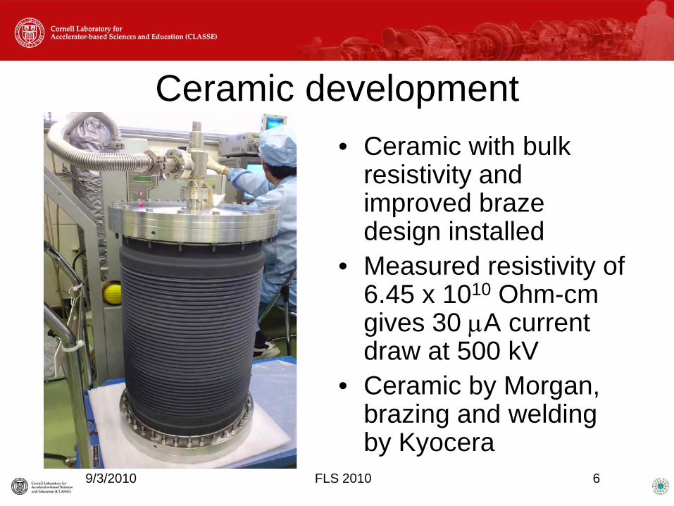
Ceramic development• Ceramic with bulk
resistivity and improved braze design installed
• Measured resistivity of 6.45 x 10¹⁰ Ohm-cm gives 30 µA current draw at 500 kV
• Ceramic by Morgan, brazing and welding by Kyocera
FLS 2010
9/3/2010 7
Electrode Preparation and Current Gun Performance
For the most recent gun assembly, with thenew resistive ceramic, the full 316L electrodeassembly was electro-polished, high pressurewater rinsed (HPR), baked in air at 400 C for100 hours, given a second HPR, and blownwith high pressure, ultra-filtered dry nitrogenuntil a particulate counter registered nothing.Subsequent HV processing reached 445 kV(12.1 MV/m peak field), and had a punchthrough failure.
FLS 2010
9/3/2010 8
The Next Ceramic• A resistive ceramic does NOT prevent punch
through failures• To eliminate punch through, it is necessary
to prevent electrons from depositing energy in the ceramic – i.e. to stop them
• This requires metallic shielding of the ceramic inner surface – and thus a segmented ceramic design
• Shield rings need high thermal conductivity and high hardness
FLS 2010
9/3/2010 9
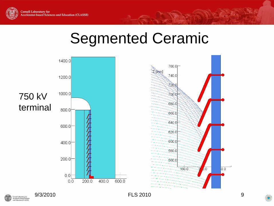
Segmented Ceramic
750 kVterminal
FLS 2010
9/3/2010 10
Segmented Ceramic Design• Built on 22 inch wire seal flanges, the
larger inner diameter allows reduction ofthe field on the electrode support tube to<12 MV/m at 750 kV
• Copper (or CuBe) shield rings required forgood thermal conductivity and hardness
• May fabricate in two sections, to allow athree-electrode gun design in the future.
• Detailed design nearing completionFLS 2010
9/3/2010 11
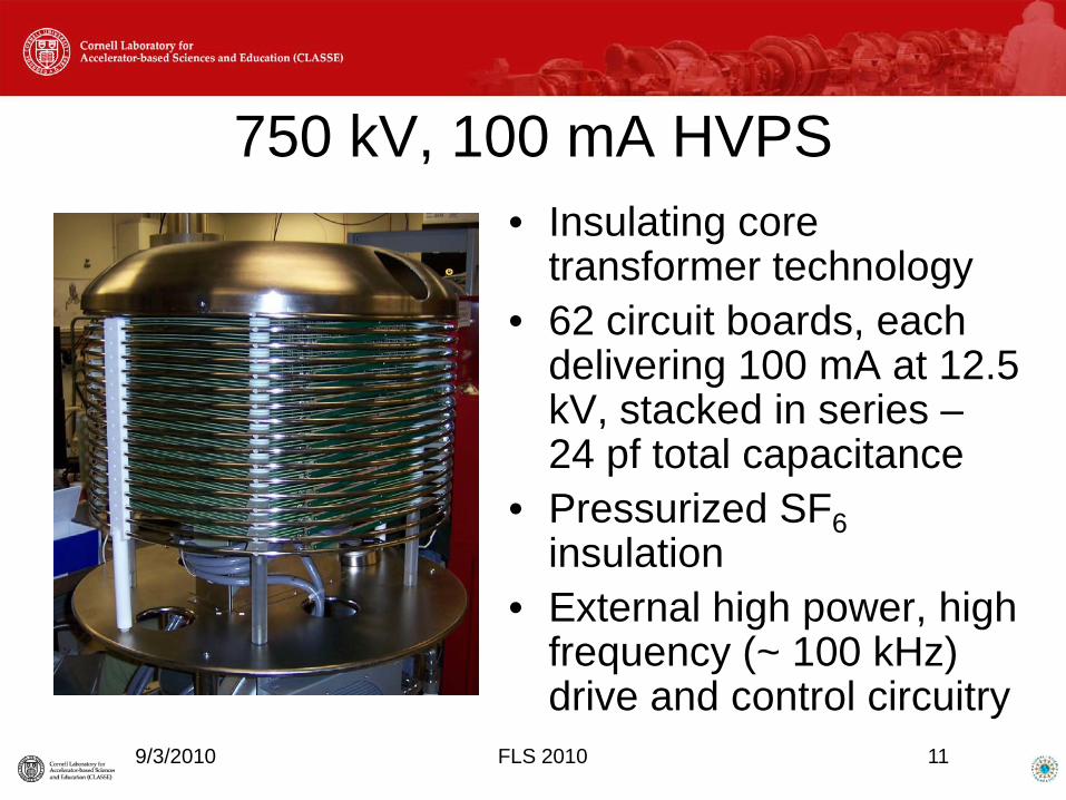
750 kV, 100 mA HVPS• Insulating core
transformer technology• 62 circuit boards, each
delivering 100 mA at 12.5 kV, stacked in series –24 pf total capacitance
• Pressurized SF6insulation
• External high power, high frequency (~ 100 kHz) drive and control circuitry
FLS 2010
9/3/2010 12
HVPS issues• Original controls unstable during operation at
reduced voltage and/or current. A fixed load resistor drawing ~ 2 mA improved stability.
• Returned to Kaiser Systems for re-work –redesigned circuit boards, control circuitry, and high power driver are being installed.
• Currently operating at 30 mA, full voltage, with greatly improved stability.
• Additional 600 kV, 100 mA supply on order, to support cathode and gun test lab operation.
FLS 2010
9/3/2010 13
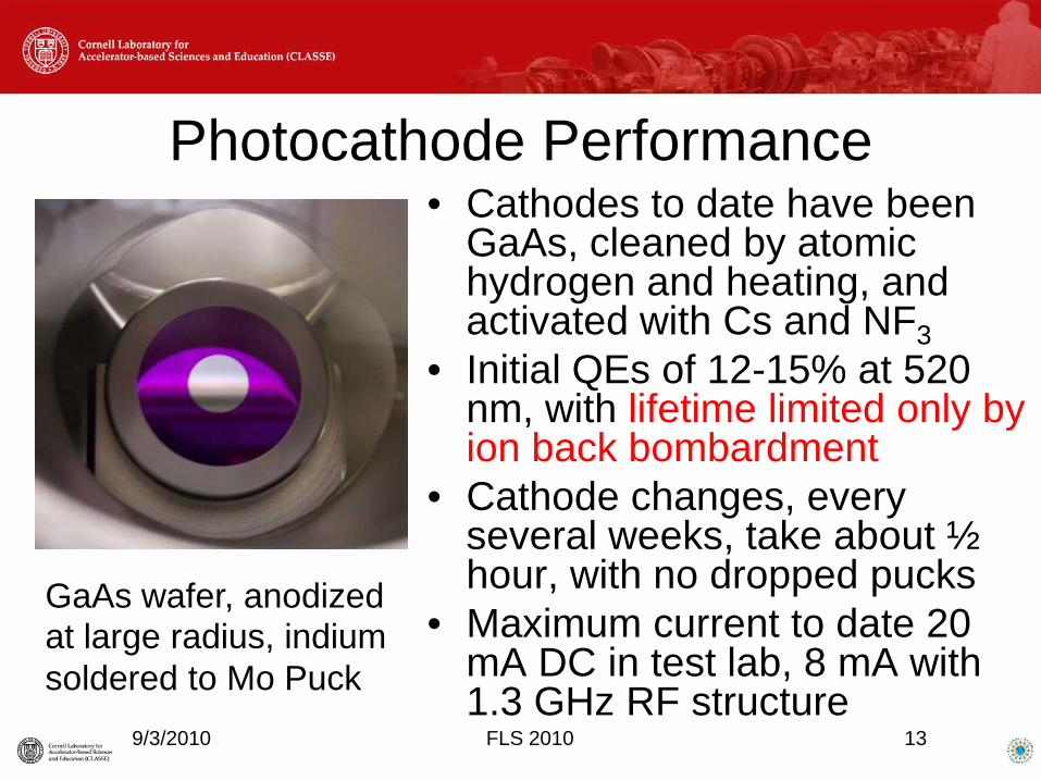
Photocathode Performance• Cathodes to date have been
GaAs, cleaned by atomic hydrogen and heating, and activated with Cs and NF3
• Initial QEs of 12-15% at 520 nm, with lifetime limited only by ion back bombardment
• Cathode changes, every several weeks, take about ½ hour, with no dropped pucks
• Maximum current to date 20 mA DC in test lab, 8 mA with 1.3 GHz RF structure
FLS 2010
GaAs wafer, anodizedat large radius, indiumsoldered to Mo Puck
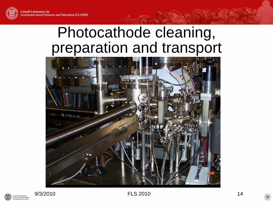
Photocathode cleaning, preparation and transport
9/3/2010 FLS 2010 14
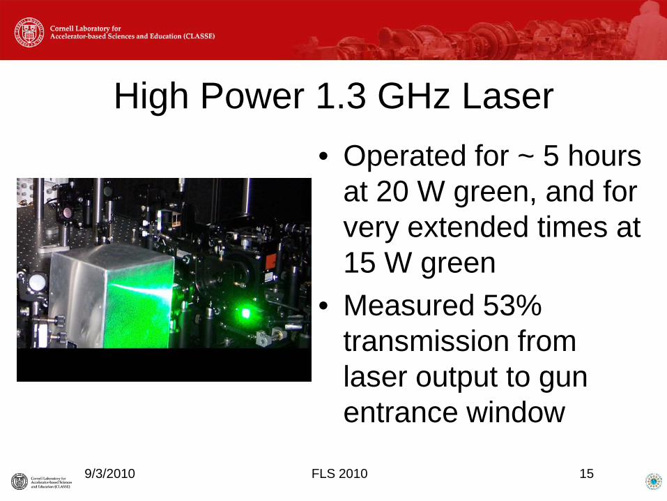
High Power 1.3 GHz Laser• Operated for ~ 5 hours
at 20 W green, and for very extended times at 15 W green
• Measured 53% transmission from laser output to gun entrance window
9/3/2010 15FLS 2010
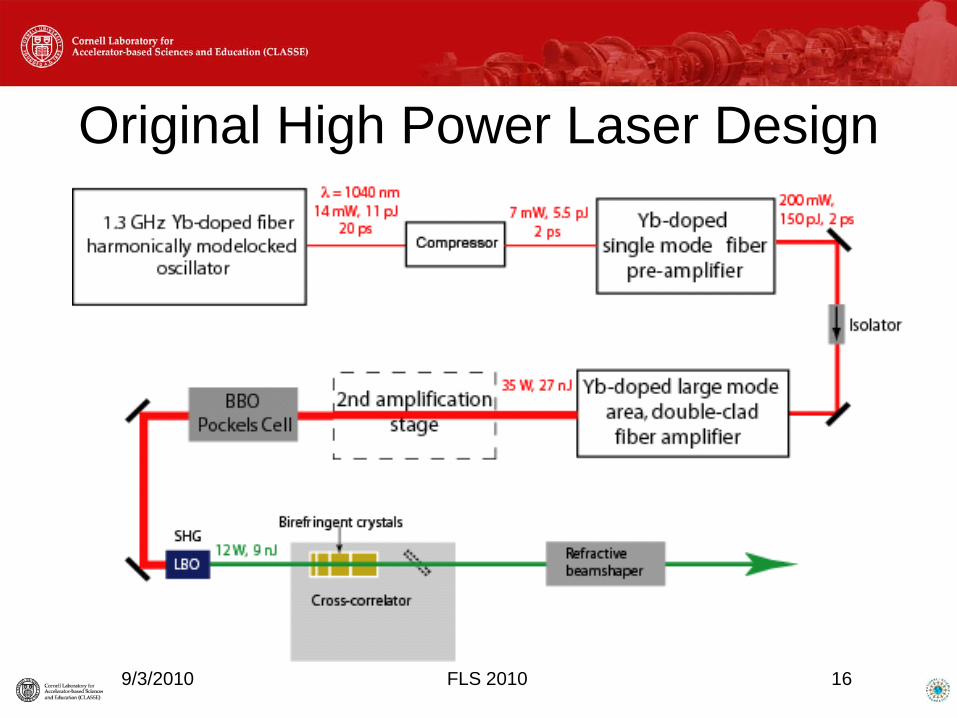
Original High Power Laser Design
9/3/2010 16FLS 2010
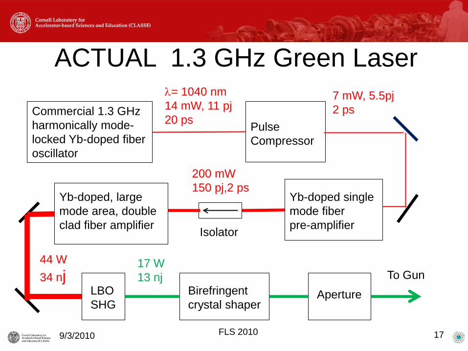
9/3/2010 17
Commercial 1.3 GHzharmonically mode-locked Yb-doped fiber oscillator
Pulse Compressor
λ= 1040 nm14 mW, 11 pj20 ps
7 mW, 5.5pj2 ps
Yb-doped single mode fiberpre-amplifier
200 mW150 pj,2 ps
Isolator
Yb-doped, large mode area, doubleclad fiber amplifier
44 W34 nj
LBOSHG
Birefringentcrystal shaper
17 W13 nj
Aperture
To Gun
ACTUAL 1.3 GHz Green Laser
FLS 2010
High Power Laser, continued
• Fiber burning problem fixed by cooling gain fiber. This should allow doubling the IR pump power, giving ~ 40 W green
• Use the original 50 MHz laser with the BBO Pockels Cell for full bunch charge beam measurements at low duty factor
• Elimination of thermal and mechanical noise sources underway
9/3/2010 18FLS 2010
Gun and Cathode Development Lab• Restoring original Gun test lab capabilities,
with gun operation to 600 kV, 100 mA• Photocathode physicist hired• Surface analysis equipment in hand (Auger,
LEED….)• Constructing system to measure cathode
transverse and longitudinal energy• Adding 300 kV field emission test stand
9/3/2010 FLS 2010 19

Gun Development Lab Beamline
9/3/2010 FLS 2010 20
9/3/2010 21
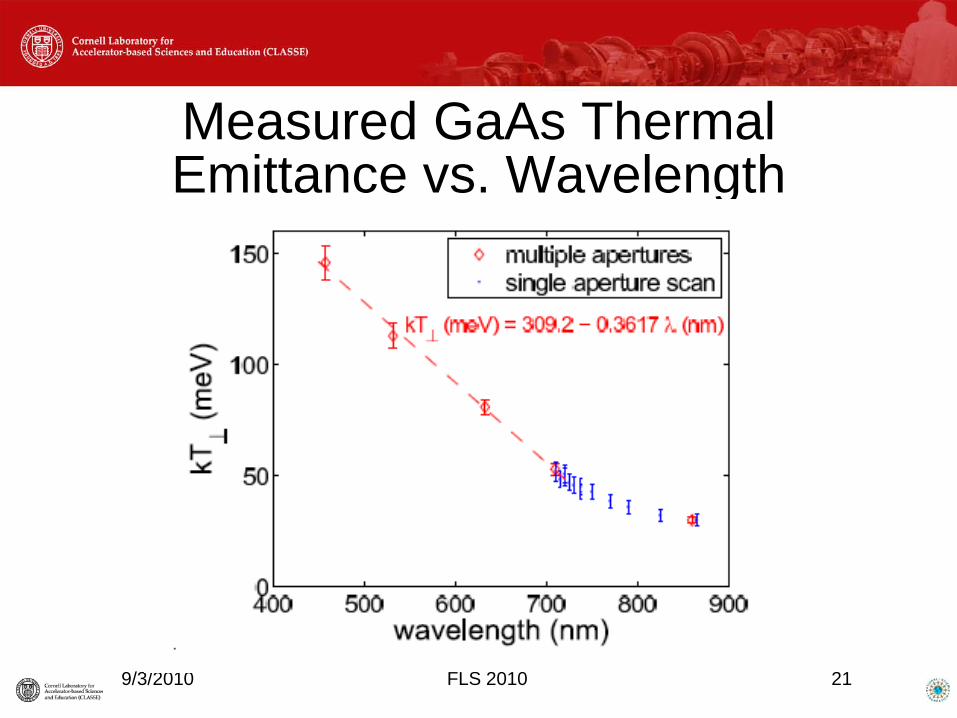
Measured GaAs Thermal Emittance vs. Wavelength
FLS 2010
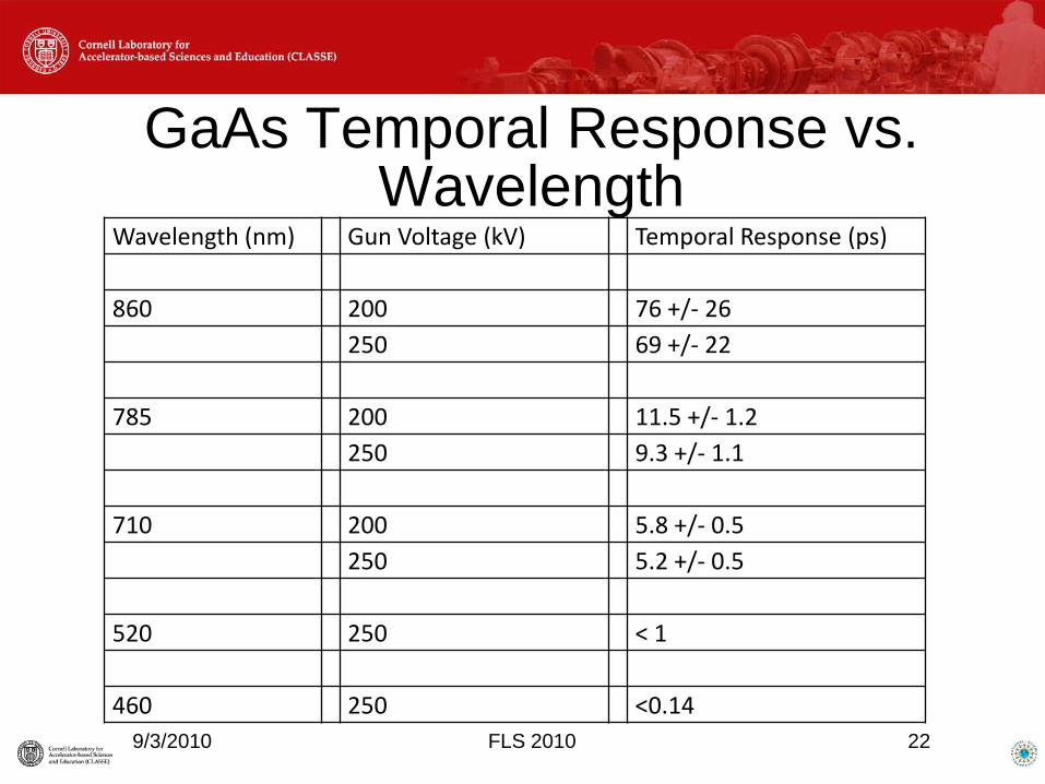
GaAs Temporal Response vs. Wavelength
9/3/2010 FLS 2010 22
Wavelength (nm) Gun Voltage (kV) Temporal Response (ps)
860 200 76 +/- 26250 69 +/- 22
785 200 11.5 +/- 1.2250 9.3 +/- 1.1
710 200 5.8 +/- 0.5250 5.2 +/- 0.5
520 250 < 1
460 250 <0.14
HVDC Gun Challenges• Eliminating or mitigating the effects of
field emission is the greatest challenge• Inverted gun design?• Process with heavy gas (krypton)?• Conductive glass or dielectric coatings?• Three electrode design?
• Reduce cathode thermal emittance, so a lower field gives the same brightness?
9/3/2010 FLS 2010 23
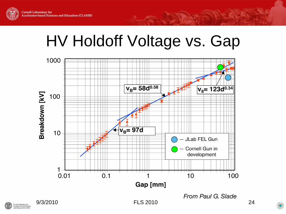
HV Holdoff Voltage vs. Gap
9/3/2010 FLS 2010 24
Laser Challenges
• Transverse shaping• More longitudinal shaping crystals• Coatings cannot take high CW power• Generating full charge bunches at very
low duty factor, without “ghost” pulses• Eliminate thermal, mechanical and
electrical noise sources
9/3/2010 FLS 2010 25
Summary• Field Emission remains the predominant
problem for HVDC photoemission electron guns
• Cathode, laser, HVPS and vacuum issues are challenging but solvable for a 100 mA average current source
• Well equipped cathode characterization and gun development laboratory being assembled9/3/2010 FLS 2010 26
Summary, cont’d• New gun design, incorporating a large
segmented insulator and vacuum improvements, is underway
• Beam operation with full injector will resume this month, at reduced voltage (ca. 350-375 kV)
9/3/2010 FLS 2010 27