Embed Size (px)
DESCRIPTION
validation
Citation preview
Validation Plan
For
H V A C
(Heating, Ventilation and Air Conditioning)
System in Sterile Area
(XXX pharmaceutical manufacturing Company)
Effective Date:
Version No.: 1.0 Validation Plan for HVAC System in Sterile Area
Validation Plan No.:
VP/MSC/001/R0
Page 2 of 51
VALIDATION PLAN APPROVAL
Written by : Validation Engineer
Name : Signature : Date : Reviewed and Approved By: Validation Manager
Name : Signature : Date : Reviewed and Approved By: Engineering Manager
Name : Signature : Date :
Reviewed and Approved By: Production Manager
Name : Signature : Date :
Reviewed and Approved By: Quality Control Manager
Name : Signature : Date :
Reviewed and Approved By: Quality Assurance Manager
Name : Signature : Date :
Approved By: Quality Unit Manager
Name : Signature : Date :

Effective Date:
Version No.: 1.0 Validation Plan for HVAC System in Sterile Area
Validation Plan No.:
VP/MSC/001/R0
Page 3 of 51
TABLE OF CONTENTS
Sl # Titles Page Numbers
1. Purpose 5
2. Objective 5
3. Scope 5
4. Quality standards 5
5. System boundaries 6
6. Area Description (Sterile Area) 6
7. Requirement for Materials and Equipment 9
8. System Description 10
9. Responsibilities 12
10. Training Requirements 13
11. Aseptic systems impact/Criticality Assessment 14
12. Validation Approach 15
13. Installation Qualification 18
14. Operational Qualification 28
15. Performance Qualification 38
16. Planning and Cost 46
17. Discrepancy/ Justification And Corrective Action 46
18. Validation 46
19. Modification/ Change Control During Qualification 46
20. Re-qualification 47
21. References and Related Records 47
22. Definitions 48
23. Glossary 48
24. History 50
25. Attachments 51
26. System Qualification Statement And Qualification Summary 51
27. Control of qualification protocol format 51
Effective Date:
Version No.: 1.0 Validation Plan for HVAC System in Sterile Area
Validation Plan No.:
VP/MSC/001/R0
Page 4 of 51
Introduction: Pharmaceutical rules and specifications are often contains very precise but
also generally formulated requirements of air conditioning technology, such as “temperature,
humidity and ventilation of premises should be adequate”. This generally formulated
requirement is partially substantiated in the supplementary guidelines of the EU GMP
Guideline for the manufacture of sterile products.
Two basic types are distinguished by the terms of Room Ventilation Technology and
Process Air Conditioning Technology. Both types are found and required in the
pharmaceutical manufacturing sites. The essential task of a ventilation system is to
guarantee that the desired room conditions, such as temperature, humidity and cleanliness.
In contrast, the process air systems must guarantee the required process parameters.
General:
The HVAC system plays an important role in product, personnel, environment, instrument
and machine protection. This can be presented as clean environment, removal of hazard
contaminant and provide a suitable temperature and humidity control within acceptable noise
level by providing clean environment.
HVAC utility is designed to control the level of viable and non-viable particulate exposure that
a drug or medicinal device might receive in addition to regulating temperature and relative
humidity conditions. HVAC utility is qualified to demonstrate operating conditions of the area.
The areas serviced by the HVAC utility are classified based on viable and non-viable
particulate levels during static operating conditions and dynamic operating conditions.
Effective Date:
Version No.: 1.0 Validation Plan for HVAC System in Sterile Area
Validation Plan No.:
VP/MSC/001/R0
Page 5 of 51
1. Purpose: The purpose of validation plan is to schedule the tasks to demonstrate the plan on HVAC system in Sterile Area. This plan will define who will be responsible to initiate, execute, review and approve each task assigned, how the data/document will be generated and what the entire validation package will be compiled and collected. This validation plan is being written in compliance with validation master plan (VMP).
2. Objective: The objective of this Validation plan is to demonstrate and document that all components, control systems and processes functionality associated with the HVAC system that appropriates in accordance with current Good Manufacturing Practices (cGMP) regulatory aspect for sterile area.
2.1 HVAC is designed to control the level of viable and non-viable particulate exposure that a drug receives in addition to regulating temperature and relative humidity conditions.
3. Scope: This validation plan is limited to HVAC system in sterile area designed for aseptic filling process in XXX Company, which is located in facility no. YYYYYYY.
4. Quality standards: The HVAC system must supply quality air which should be in compliance to all standards according to:
4.1 AS/NZS ISO 14644.1:2002: Clean room and associated controlled environments, part 1: classification and air cleanliness.
4.2 AS/NZS ISO 14644.2:2002: Clean room and associated controlled environments, part 2: specification for testing and monitoring to prove continued compliance with ISO 14644.1.
4.3 AS/NZS ISO 14644.4:2002: Clean room and associated controlled environments, part 4: design, construction and start up.
4.4 ISO EN 14644.5:2004: Clean room and associated controlled environments, part 5: clean room operations
4.5 PIC/S Guideline to GMP for medicinal product
4.6 ISPE Baseline guide volume 3, sterile manufacturing facility
4.7 AS 1386.31989 Cleanrooms and clean workstation part 1&3
4.8 EU GMP Guide, Volume IV GMP for medicinal products section 3 premises and equipment
4.9 21CFR part 11 Subpart C building and facility and subpart D
4.10 United stat Pharmacopeia USP 32
4.11 European Pharmacopeia Ph Eur 7th Edition
4.12 ISO/IEC 17025 General requirements for the competence and testing of calibration and testing laboratories

Effective Date:
Version No.: 1.0 Validation Plan for HVAC System in Sterile Area
Validation Plan No.:
VP/MSC/001/R0
Page 6 of 51
5. System boundaries: The physical boundaries are defined as follows:
5.1 Source of air handling units (AHUs) and air conditioning units (ACUs) including other forms of air pretreatment (e.g., heating/cooling, dehumidification/ humidification), Attachment No.2 – Diagram for Sterile Area.
5.1.1 AHUs require externally supplied heating and cooling sources such as steam, hot water, or chilled water.
5.1.2 ACUs are self-contained with respect to heating and cooling, and generally employ a refrigeration-based heat pump. They may be reversible and both heat and cool the supply airflow.
5.1.3 AHUs, ACUs, and associated ductwork, which supply air to critical and controlled areas/rooms, are included, while AHUs, ACUs, and related ductwork, which supply non-GMP; uncontrolled areas (e.g., offices, cafeterias) are not included.
5.2 Supply air and return air ductwork up to, but not including, grills inside rooms or areas.
5.3 Support utility interfaces (e.g., electrical connections at disconnect points) for heating/cooling water supplies, etc.
6. Area Description (Sterile Area)
6.1 This area is defined to use only sterile oriented products for manufacturing. The aseptic process involves the handling of sterile components until they are sealed in their final containers.
6.2 Aseptic area is designed, constructed and engineered to comply with pharmaceutical compliance standards and to prevent microbial contamination.
6.3 The clean room for the aseptic area is classified according to the required characteristics of the environment. The “in-operation” and “at rest” states should be defined for each clean room or suites as mentioned in the below-mentioned grade:
6.3.1. Grade A: The local zone for high-risk operations includes aseptic filling zone, stopper bowls, open vials and making aseptic connections. This zone is equipped with laminar flow systems with homogenous air speed in a range of 0.36 to 0.54m/s.
6.3.2. Grade B: This is the background environment for grade A zone.
6.3.3. Grade C: Clean areas for carrying out less critical stages in the manufacture of sterile products.
6.3.4. Grade D: This area is unclassified, as it is meant for capping gowning room and black/grey change room.
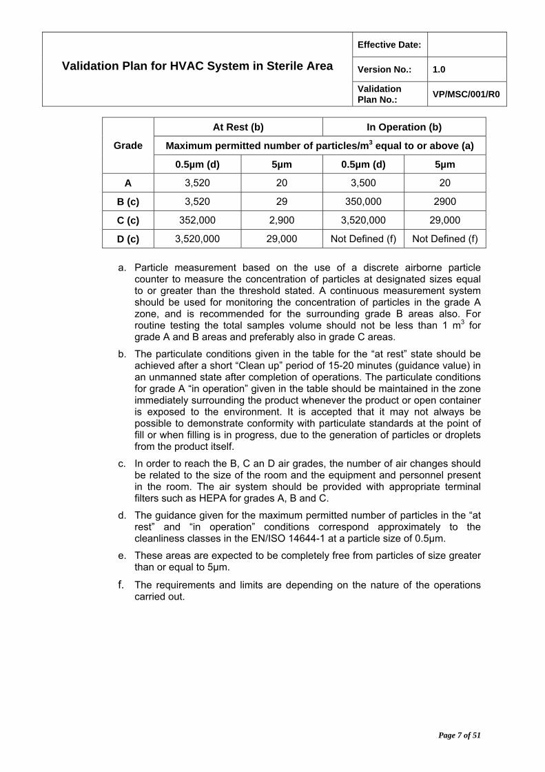
6.3.5. The airborne particulate classification for these grades are given in the following table:
Effective Date:
Version No.: 1.0 Validation Plan for HVAC System in Sterile Area
Validation Plan No.:
VP/MSC/001/R0
Page 7 of 51
At Rest (b) In Operation (b)
Maximum permitted number of particles/m3 equal to or above (a) Grade
0.5µm (d) 5µm 0.5µm (d) 5µm
A 3,520 20 3,500 20
B (c) 3,520 29 350,000 2900
C (c) 352,000 2,900 3,520,000 29,000
D (c) 3,520,000 29,000 Not Defined (f) Not Defined (f)
a. Particle measurement based on the use of a discrete airborne particle counter to measure the concentration of particles at designated sizes equal to or greater than the threshold stated. A continuous measurement system should be used for monitoring the concentration of particles in the grade A zone, and is recommended for the surrounding grade B areas also. For routine testing the total samples volume should not be less than 1 m3 for grade A and B areas and preferably also in grade C areas.
b. The particulate conditions given in the table for the “at rest” state should be achieved after a short “Clean up” period of 15-20 minutes (guidance value) in an unmanned state after completion of operations. The particulate conditions for grade A “in operation” given in the table should be maintained in the zone immediately surrounding the product whenever the product or open container is exposed to the environment. It is accepted that it may not always be possible to demonstrate conformity with particulate standards at the point of fill or when filling is in progress, due to the generation of particles or droplets from the product itself.
c. In order to reach the B, C an D air grades, the number of air changes should be related to the size of the room and the equipment and personnel present in the room. The air system should be provided with appropriate terminal filters such as HEPA for grades A, B and C.
d. The guidance given for the maximum permitted number of particles in the “at rest” and “in operation” conditions correspond approximately to the cleanliness classes in the EN/ISO 14644-1 at a particle size of 0.5µm.
e. These areas are expected to be completely free from particles of size greater than or equal to 5µm.
f. The requirements and limits are depending on the nature of the operations carried out.

Effective Date:
Version No.: 1.0 Validation Plan for HVAC System in Sterile Area
Validation Plan No.:
VP/MSC/001/R0
Page 8 of 51
6.4 The area is designed also in accordance to following US FDA classification.
Class Name Particle Size
ISO Class U.S. FS 209E ISO, m3 FS 209E, ft.3
3 Class 1 35.2 1
4 Class 10 352 10
5 Class 100 3520 100
6 Class 1000 35,200 1000
7 Class 10,000 352,000 10,000
8 Class 100,000 3,520,000 100,000
Adapted from the Federal Standard no. 209E, General Services Administration, Washington DC, 20407 (September 11, 1992) and also [4644-1:1999 Clean rooms and associated controlled environments-part 1: Classification of air cleanliness. For example, 3520 particles of 0.5µm per m3 or larger (ISO class 5) is equivalent to 1000 particles per ft3 (class 100) (1m3 = 34.314ft3).
6.5 Cleanliness Phase
Cleanliness grade A (FS 209 E class 100 at rest) ISO 5 US class 100 in operation SI M* 3.5
The local zone for operations with a high level of risk, for example in the filling area, assembly of the filling apparatus (pump, filter, etc.), aseptic connections (equipment, tubes, couplings) under laminar airflow of 0.45 m/s 20%.
Microbiological limit <1 CFU/m3 In the case of faults, controlled, brief intervention by
personnel from cleanliness grade B is permitted.
Cleanliness grade B (FS 209 E class 100 at rest) ISO 5 US class 10.000 in operation SI M* 5.5
The presence of appropriately dressed personnel is permitted.
Turbulent airflow is permitted. Microbiological limit 10 CFU/m3 (action limit)
(FS 209 E class 10 000 at rest) ISO 7 US class 100.000 in operation SI M* 6.5
The presence of appropriately dressed personnel is permitted.
Turbulent airflow is permitted. Microbiological limit 100 CFU/m3 (action limit)
Cleanliness grade D (FS 209 E class 100 000 at rest) ISO 8 US class: not classified
The presence of appropriately dressed personnel is permitted.
Turbulent airflow is permitted. Microbiological limit 200 CFU/m3 (action limit
SI M represents the classification on the basis of 0.5m particles
Limits for the microbial contamination of surfaces in these cleanliness grades are generally tested with purchased nutrition agar contact plates with a diameter of 55 mm (corresponds to a surface area of 23.75 cm2). Therefore need to consider the specifications per cm2 and include them in standard operating procedures (SOPs). To be on the safe side, you can comply with the required limit for a contact area of > 23.75 cm2. Normally, specifications are provided per plate with a diameter of 55mm or per 25 cm2
Effective Date:
Version No.: 1.0 Validation Plan for HVAC System in Sterile Area
Validation Plan No.:
VP/MSC/001/R0
Page 9 of 51
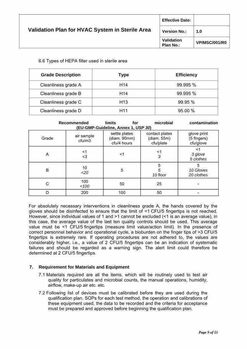
6.6 Types of HEPA filter used in sterile area
Grade Description Type Efficiency
Cleanliness grade A H14 99.995 %
Cleanliness grade B H14 99.995 %
Cleanliness grade C H13 99.95 %
Cleanliness grade D H11 95.00 %
Recommended limits for microbial contamination
(EU-GMP-Guideline, Annex 1, USP 30)
Grade air sample
cfu/m3
settle plates (diam. 90mm)
cfu/4 hours
contact plates (diam. 55m)
cfu/plate
glove print (5 fingers) cfu/glove
A <1 <3
<1 <1 3
<1 3 glove
5 clothes
B 10
<20 5
5 5
10 floor
5 10 Gloves 20 clothes
C 100
<100 50 25 -
D 200 100 50 -
For absolutely necessary interventions in cleanliness grade A, the hands covered by the gloves should be disinfected to ensure that the limit of <1 CFU/5 fingertips is not reached. However, since individual values of 1 and >1 cannot be excluded (<1 is an average value), in this case, the average value of the last ten quality controls should be used. This average value must be <1 CFU/5 fingertips (measure limit value/action limit). In the presence of correct personnel behavior and operational cycle, a bioburden on the finger tips of >3 CFU/5 fingertips is extremely rare. If operating procedures are not adhered to, the values are considerably higher, i.e., a value of 2 CFU/5 fingertips can be an indication of systematic failures and should be regarded as a warning sign. The alert limit could therefore be determined at 2 CFU/5 fingertips.
7. Requirement for Materials and Equipment
7.1 Materials required are all the items, which will be routinely used to test air quality for particulates and microbial counts, the manual operations, humidity, airflow, make-up air etc. etc.
7.2 Following list of devices must be calibrated before they are used during the qualification plan. SOPs for each test method, the operation and calibrations of these equipment used, the data to be recorded and the criteria for acceptance must be prepared and approved before beginning the qualification plan.
Effective Date:
Version No.: 1.0 Validation Plan for HVAC System in Sterile Area
Validation Plan No.:
VP/MSC/001/R0
Page 10 of 51
7.2.1 Micro-manometer
7.2.2 Differential Pressure Gauge.
7.2.3 Thermal Anemometer
7.2.4 Vane-type Anemometer
7.2.5 Multi-parameter ventilation meter
7.2.6 Air Capture hood
7.2.7 Thermo hygrometer
7.2.8 Indoor Air Quality Meter
7.2.9 Compulsion Analyzer
7.2.10 Air Velocity Transducer
7.2.11 Micro-Ohmmeter with airflow hood
7.2.12 Particle Counter
7.2.13 Microbiological Air Sampler and Media Plates
7.2.14 Charts for the time, temperature and pressure recording.
7.2.15 Aerosol generator
7.2.16 Photometer
8. System Description: HVAC system is fully integrated air conditioning and filtration system that consists of Air Handling Unit (AHU), fans, filters, and ductwork, heating and cooling system, gauges and control system. The details of components are described in attachment no. 1.
8.1 Air Handling Unit: AHU is constructed in a horizontal modular, located within the plant roof area.
8.1.1. Weather Louver: To prevent insect, eaves, dirt and rain from entering.
8.1.2. Separator: Providing primary filtration for the fresh air with steady pressure drop.
8.1.3. Pre-filter: Filtration of the fresh air and have resistance to the standard of EUROVENT 3 and 7 respectively.
8.1.4. Mixing/Exhaust Plenums: Fitted with parallel blade dampers which operation is extended via drive spindles that is suitable for hand adjustment and lockable.
8.1.5. Electric Heating Coil: To heat the air to the proper temperature. (Fitted with over heat cutout that is of auto-reset type.)
8.1.6. Cooling Unit/dehumidifier: To cool the air to the required temperature or to remove moisture from the air.
8.1.7. Humidifier: To bring the air to the proper humidity, if too low.
8.1.8. Secondary Filters: To eliminate particles of pre-determined dimensions and/or microorganisms according to the user requirement specification.
Effective Date:
Version No.: 1.0 Validation Plan for HVAC System in Sterile Area
Validation Plan No.:
VP/MSC/001/R0
Page 11 of 51
8.1.9. Fan: The fan is multivane backward curved centrifugal, to suite the volume/pressure characteristics required with double inlet, double width impeller.
8.1.10. Air Cooled Chillers: The chiller has two refrigerant circuits allowing for close control of the chilled water circuit serving the Air Handling Unit cooler battery and service void fan unit under a wide range of cooling loads.
8.1.11. Ductwork: All of the supply and general extract ductwork is installed and manufactured from galvanized mild steel in accordance with HVAC specification DW142 low-pressure classification. (Ductwork must be kept clean during manufacturing and installation and it must be performed in accordance with HVAC DW/TM2 intermediate level).
8.1.12. Terminal Filter: The final filtration within the Cephalosporin suite must be with 99.999% efficient HEPA filters.
8.1.13. Pressure Indication: This continuously monitors the pressures of each room, the air handling unit filter’s pressure drop, the return air filter pressure drop and typical supply HEPA filter pressure drop, this being one of the filters in the filling room.
8.1.14. Gas fumigation system: The air handling system is controlled by sequence timers which are adjustable, to allow for the air handling system to be shut down on commencement of fumigation together with the closing of the airtight dampers in the main supply and return ducts.
8.1.14.1. The fumigation sockets are energized for an appropriate period then de-energized for a further contact or kill period-stipulated time that mentioned in the XXX SOP. Once the kill period timer has elapsed, the air handling systems are automatically re-started with warnings lamps illuminated indicating that the plant is in “degas” mode. On completion of the pre-set degas period, the HVAC for sterile systems continue to run and degas lights will switch off automatically.
8.2 Room Classification
Room ID Room Description Rooms Classification at
rest conditions.

Effective Date:
Version No.: 1.0 Validation Plan for HVAC System in Sterile Area
Validation Plan No.:
VP/MSC/001/R0
Page 12 of 51
9. Responsibilities
The responsibility of the following individuals and departments as defined with reference to validation master plan VMP001\R0
9.1 Responsibility of XXX Management:
9.1.1. Review and approve of this validation plan (VP), validation protocol, reports, requirement specification, planning, project management and final validation plan summary report approval.
9.1.2. Control of plan recourses, cost, activity and continuous monitoring the process
9.1.3. Monitoring the corrective and preventive action, as well to ensure from completeness for each stage before transfer to the next stage.
9.1.4. Support and approval from quality assurance to ensure the complete compliance of GMP rules and regulations.
9.2 Responsibility of Vendor includes:
9.2.1. Supply of all manuals, drawings, maintenance procedures, data, spare parts list, etc...
9.2.2. Equipment Installation and training.
9.3 Responsibilities of Validation Department
9.3.1. Auditing VP implementation.
9.3.2. Writing of VP and protocols.
9.3.3. Providing appropriate personnel to conduct the validation activity.
9.3.4. Execution of validation activity with vendor.
9.3.5. To review and approve the final validation summary report after ensuring that the records are in order.
9.3.6. To ensure that all other related departments follow the approved validation plan and protocols.
9.4 Responsibilities of Engineering Department
9.4.1. Reviewing and approving the VP and protocols.
9.4.2. To provide the required supporting utilities as per the standard tests procedure and report the results
9.4.3. Initial receipt and inspection of the HVAC System.
9.4.4. Training of Engineering personnel
9.4.5. Ensuring that the HVAC (FAC001) system is ready for conducting the qualification at different consecutive stages.
9.4.6. Providing technical support by trained and qualified engineering personnel during the execution of VP.
9.4.7. Developing and finalizing the HVAC (FAC001) operation, cleaning and preventive maintenance standard operating procedure (SOP).
Effective Date:
Version No.: 1.0 Validation Plan for HVAC System in Sterile Area
Validation Plan No.:
VP/MSC/001/R0
Page 13 of 51
9.4.8. Reviewing and approving the VP, protocols and summary reports.
9.5 Responsibilities of production Department (System Owner)
9.5.1. Reviewing and approving of VP, protocols and reports.
9.5.2. Coordination and conformation with Engineering Department that the facility is ready for conducting the validation plan at different stages.
9.5.3. Providing trained and qualified production personnel to insure from completeness of validation plan to be able to initiate the related SOP for related to production activity.
9.5.4. Reviewing and approving the VP, protocols and summery reports .
9.6 Responsibilities of Quality Control Department
9.6.1. Reviewing and approving the VP, protocols and summery reports
9.6.2. Provide qualified and trained personnel to execute the related validation activity and generate and reporting the related records according to the approved procedures and protocols.
9.7 Responsibilities of Quality Assurance Department
9.7.1. Reviewing and approving the VP, protocols and summery reports. after ensuring that all the records are in order
9.7.2. Ensuring that all other related departments follow up the approved VP and protocols.
9.7.3. Assuring compliance with all regulations and XXX requirements
10. Training Requirements: Training plan must be generated, approved and executed to
identify what kind of trainings are required and when will it be executed by whom, and
when and what course of material and records where will be maintained.
The responsibility of Vendor for the training needs should be identified before execution
of any activity, and the training record shall indicate where, when, what, and whom to
perform the training with reference to the material used in training.
Effective Date:
Version No.: 1.0 Validation Plan for HVAC System in Sterile Area
Validation Plan No.:
VP/MSC/001/R0
Page 14 of 51
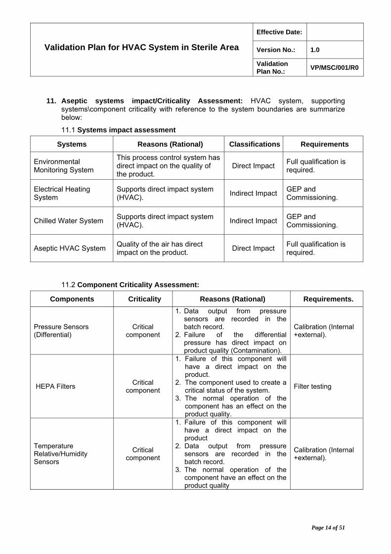
11. Aseptic systems impact/Criticality Assessment: HVAC system, supporting systems\component criticality with reference to the system boundaries are summarize below:
11.1 Systems impact assessment
Systems Reasons (Rational) Classifications Requirements
Environmental Monitoring System
This process control system has direct impact on the quality of the product.
Direct Impact Full qualification is required.
Electrical Heating System
Supports direct impact system (HVAC).
Indirect Impact GEP and Commissioning.
Chilled Water System Supports direct impact system (HVAC).
Indirect Impact GEP and Commissioning.
Aseptic HVAC System Quality of the air has direct impact on the product.
Direct Impact Full qualification is required.
11.2 Component Criticality Assessment:
Components Criticality Reasons (Rational) Requirements.
Pressure Sensors (Differential)
Critical component
1. Data output from pressure sensors are recorded in the batch record.
2. Failure of the differential pressure has direct impact on product quality (Contamination).
Calibration (Internal +external).
HEPA Filters Critical
component
1. Failure of this component will have a direct impact on the product.
2. The component used to create a critical status of the system.
3. The normal operation of the component has an effect on the product quality.
Filter testing
Temperature Relative/Humidity Sensors
Critical component
1. Failure of this component will have a direct impact on the product
2. Data output from pressure sensors are recorded in the batch record.
3. The normal operation of the component have an effect on the product quality
Calibration (Internal +external).

Effective Date:
Version No.: 1.0 Validation Plan for HVAC System in Sterile Area
Validation Plan No.:
VP/MSC/001/R0
Page 15 of 51
11.3 GMP Critical Parameters
Parameters Criticality Reasons (Rational) Requirements.
Room classification (Viable and non-viable)
GMP Critical parameter
GMP requirement Initially and on Continuous basis (monitoring) at rest & in operation.
Room Temperature GMP Critical parameter
GMP requirement Continuous monitoring
Relative humidity GMP Critical parameter
GMP requirement for Aseptic Filling
Continuous monitoring
Differential Pressure GMP Critical parameter
GMP requirement Continuous monitoring
Rates Rooms air changes GMP Critical parameter
GMP requirement Continuous monitoring
Airflow Paths GMP Critical parameter
GMP requirement Continuous monitoring
12. Validation Approach
12.1 Validation approach will be used as a prospective validation with reference to validation master plan (VMP/500/R0). The approach will be conducted in sequence of IQ OQ PQ.
12.2 V-Model Showing relationship between different stages
12.2.1 User Requirement Specification: This document shall be generated and approved to describe regarding the requirement of HVAC needs and intended to perform and all essential requirements. The owner usually develops it. This document links to the performance qualification document which tests for each of the requirements.
12.2.2 Functional Requirement Specification: This document shall be generated to describe the detailed function of HVAC system. The supplier usually develops it. This document is linked to the operation qualification document which testes for each function.
12.2.3 Design Specification: This document shall be generated and approved to support construction installation such as detailed process descriptions, narratives and diagrams, system architecture drawing, piping and instrumentation diagrams (P&IDs), control wiring diagrams, power distribution and grounding diagrams, panel layout drawings, hardware and software design specification, bill of materials, other documents required for installation, operations and maintenance.

Effective Date:
Version No.: 1.0 Validation Plan for HVAC System in Sterile Area
Validation Plan No.:
VP/MSC/001/R0
Page 16 of 51
12.2.4 The validation cycle includes the following testing specifications:
12.2.4.1 Design Qualification
12.2.4.2 Factory Acceptance Test
12.2.4.3 Site Acceptance Test
12.2.4.4 Commissioning
12.2.4.5 Installation Qualification
12.2.4.6 Operation Qualification and
12.2.4.7 Performance Qualification
Effective Date:
Version No.: 1.0 Validation Plan for HVAC System in Sterile Area
Validation Plan No.:
VP/MSC/001/R0
Page 17 of 51
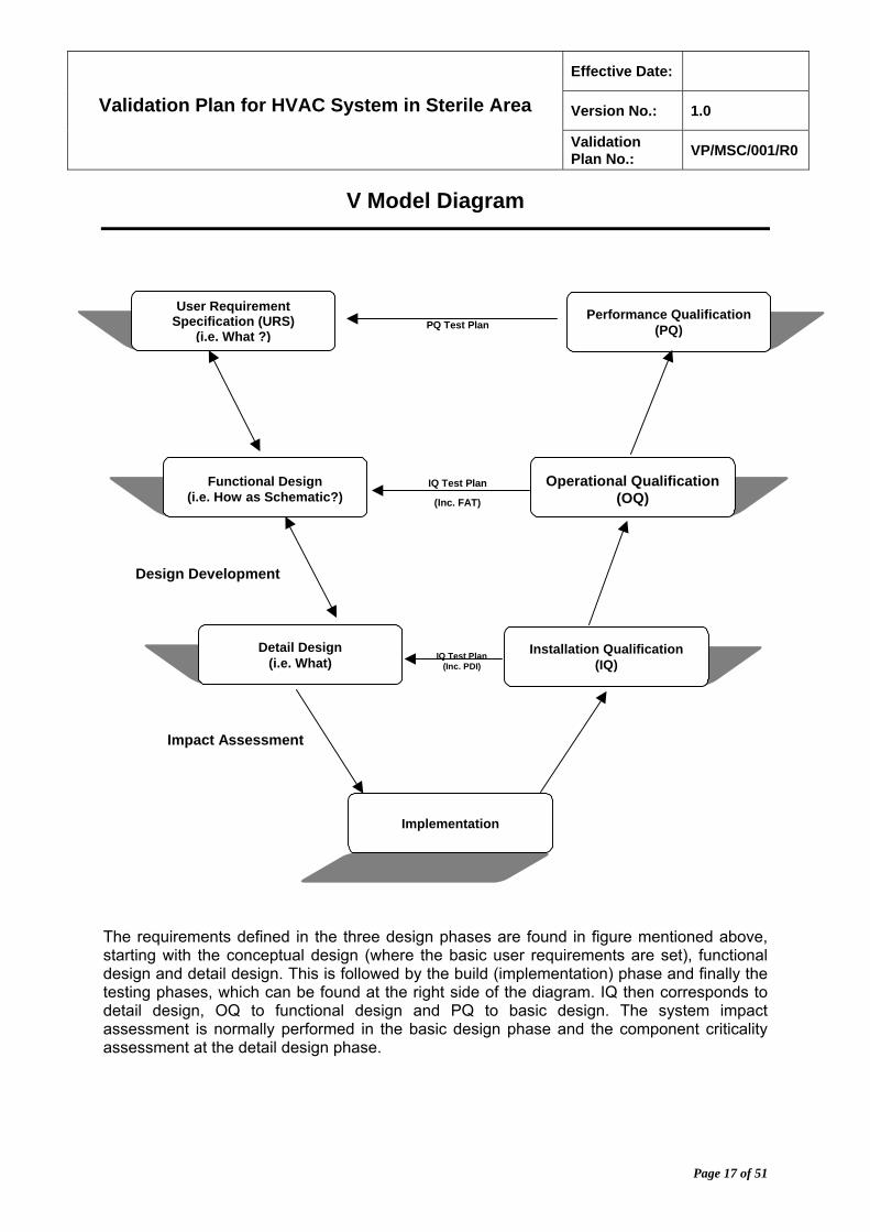
V Model Diagram
The requirements defined in the three design phases are found in figure mentioned above, starting with the conceptual design (where the basic user requirements are set), functional design and detail design. This is followed by the build (implementation) phase and finally the testing phases, which can be found at the right side of the diagram. IQ then corresponds to detail design, OQ to functional design and PQ to basic design. The system impact assessment is normally performed in the basic design phase and the component criticality assessment at the detail design phase.
IQ Test Plan(Inc. PDI)
IQ Test Plan
(Inc. FAT)
Design Development
Impact Assessment
User Requirement Specification (URS)
(i.e. What ?)
Functional Design (i.e. How as Schematic?)
Detail Design (i.e. What)
Implementation
Performance Qualification (PQ)
Operational Qualification (OQ)
Installation Qualification (IQ)
PQ Test Plan
Effective Date:
Version No.: 1.0 Validation Plan for HVAC System in Sterile Area
Validation Plan No.:
VP/MSC/001/R0
Page 18 of 51
13. Installation Qualification
The objective for installation qualification (IQ) is to demonstrate that the HVAC system (Model No. 000) in sterile area is in conformance to the URS and manufacture literature. The information must be documented that the equipment meets specification.
Installation qualification (IQ) protocol No IQP\VD\01\R00 shall be generated; the following qualification tests will be included in the IQ protocol and protocol must be prepared according to SOP-VD-010.
The proper installation of the system components must be in accordance to the URS and manufacturer’s recommendation and the workmanship standard that are set in the engineering specification.
i. To provide the elements that will verify the following for all new components of the HVAC system that have been installed:
i.1 Components are included with their approved design and engineering specification.
i.2 Ensure that they are properly served by the required utilities, such as electric power, chilled water, pure steam plant, compressed air and such.
i.3 Ensure that components are installed at the specified locations.
i.4 All critical measuring instruments and gauges are calibrated against traceable primary instrument.
i.5 Operation manuals and spare parts lists must be available to assure the proper and continuous operations systems.
i.6 Ensure that they are properly reflected in as-built systems.
ii. The following documents must be provided:
ii.1 Purchase orders for major components.
ii.2 Factory Acceptance Test Report (FAT).
ii.3 Copy of User Requirement Specification (URS).
iii. Installation Qualification (IQ) Tests:
iii.1 The following qualifications for IQ are listed as plan: Successful execution of the activities will certify the performance for HVAC system.
iii.1.1. High Efficiency Particulate Air (HEPA) audit:
iii.1.1.1. HVAC Systems for critical and controlled areas (see below) employ HEPA filters to remove particles, which are suspended in the supply air stream before it enters the area. The concentration of particles in such areas is under regulatory control (limits are tabulated under the point no. 6.3.5).
iii.1.1.2. In order to reliably remove particles before they can enter critical or controlled areas and possibly may contaminate
Effective Date:
Version No.: 1.0 Validation Plan for HVAC System in Sterile Area
Validation Plan No.:
VP/MSC/001/R0
Page 19 of 51
product, the HEPA filters must be integral (i.e., must be leak free).
iii.1.1.3. An Audit of all HEPA Filter Integrity Testing Documentation for each HEPA filter installed must be conducted. This documentation must be reviewed to verify that each HEPA filter installed has passed integrity testing (post installation testing).
iii.1.1.4. The information to be reviewed that includes the availability of the following:
iii.1.1.4.1. Procedure(s) for HEPA filter integrity testing and repair (SOP # SOP-ENGU-006).
iii.1.1.4.2. Calibration Certificates for instruments used in filter integrity testing.
iii.1.1.4.3. Documentation of serial numbers/locations of filters.
iii.1.1.4.4. Documentation of testing medium used.
iii.1.1.4.5. Repair and retesting report.
iii.1.1.4.5.1. Surface area of repairs.
iii.1.1.4.5.2. Velocity of air.
iii.1.1.4.6. Documentation of upstream concentration of testing solution.
iii.1.1.4.7. Documentation of grid location of repairs.
iii.1.1.5. Critical and Controlled Areas
iii.1.1.5.1. Critical Areas: A critical area is the area where sterilized dosage forms, containers and closures are exposed to the environment.
iii.1.1.5.2. Controlled Areas: A controlled area is the area where drug/device product, in-process materials, and container/closures with microbial contamination concerns are prepared. This includes areas where products are compounded, and where components, in-process materials, drug products and drug product contact surfaces of equipment, containers, and closures are exposed to the environment. This environment should be of a high microbial and particulate quality in order to minimize the level of particulate contaminants in the final product and to control the microbiological content (bioburden).
Effective Date:
Version No.: 1.0 Validation Plan for HVAC System in Sterile Area
Validation Plan No.:
VP/MSC/001/R0
Page 20 of 51
iii.1.2. Verification of Approved or As-Built (on site) Drawings – HVAC:
iii.1.2.1. Process and Instrumentation Drawings (P&IDs) are used to graphically represent mechanical process, piping, and ductwork systems.
iii.1.2.2. Drawings are created during the design phase of a project and once approved, serve as a portion of the specification used to build or create the system.
iii.1.2.3. Once built, the approved or as-built drawings serve as one of the most important means of documenting on paper pertaining what the system is and what it consists of.
iii.1.2.4. Modifications made to the system during installation and after installation require subsequent modification of the drawings to keep them up-to-date.
iii.1.2.5. Because of their importance to the documentation of the system, approved as-built P&IDs should be verified to ensure that they are accurately represent the installed system.
iii.1.2.6. Components that have an affect on the process such as control valves and other instrumentation should also be verified.
iii.1.2.7. The items noted should be verified for proper installation, location, and orientation in the process flow when compared with the approved or as-built P&ID.
iii.1.2.8. Typical Components in an HVAC system P & ID are given as follows:
iii.1.2.8.1. Air Handling Units:
iii.1.2.8.1.1. Manufacturer
iii.1.2.8.1.2. Model Number
iii.1.2.8.1.3. Serial Number
iii.1.2.8.1.4. Fan HP
iii.1.2.8.1.5. Electrical components
iii.1.2.8.1.6. Supply fan installed.
iii.1.2.8.1.7. Cooling coil
iii.1.2.8.1.8. Condensate collection pan
iii.1.2.8.2. Air handling heating section components
iii.1.2.8.2.1. Control valve type, Model number, serial number
iii.1.2.8.2.2. Steam Coil
iii.1.2.8.3. Air handling humidification section components.
iii.1.2.8.3.1. Humidifier, manufacturer, model.
Effective Date:
Version No.: 1.0 Validation Plan for HVAC System in Sterile Area
Validation Plan No.:
VP/MSC/001/R0
Page 21 of 51
iii.1.2.8.3.2. Pure steam connection.
iii.1.2.8.3.3. Control valve, type, model number, serial number.
iii.1.2.8.4. Air Handler filtration section components
iii.1.2.8.4.1. Pre-filters (Usually 95% ASHRAE efficient cartridges filter).
iii.1.2.8.4.2. Final filters (usually high-efficiency or HEPA filters).
iii.1.2.8.5. Air handler electrical, pneumatic, or electronic control devices.
iii.1.2.8.5.1. Type
iii.1.2.8.5.2. Location
iii.1.2.8.5.3. Range and accuracy
iii.1.2.8.5.4. Manufacturer
iii.1.2.8.5.5. ID Number
iii.1.2.8.6. Air distribution network components, ductwork, noise attenuators, dampers
iii.1.2.8.6.1. The checklist must be prepared based on the final approved engineering specification. Observation must be made on the changes or modification after issuance of specification, which would be considered as deviations from the original design.
iii.1.2.8.6.2. Cleaning inspection report must be provided.
iii.1.2.8.7. Verify the actual equipment
iii.1.2.8.7.1. ID number for all the valves must be allotted.
iii.1.2.8.7.2. Installed versus the reference specifications.
iii.1.2.8.7.3. Properly reflected in the as-built drawings.
iii.1.2.8.8. Filters and terminal filter housings:
iii.1.2.8.8.1. Specification must be provided that to be used as reference(s), include authorized change orders.
iii.1.2.8.8.2. Verify that the specified terminal filters have been installed versus the reference specification.
Effective Date:
Version No.: 1.0 Validation Plan for HVAC System in Sterile Area
Validation Plan No.:
VP/MSC/001/R0
Page 22 of 51
iii.1.2.8.8.3. List must be provided for terminal filter locations and actual serial numbers.
iii.1.2.8.9. Chilled and hot water distribution systems
iii.1.2.8.9.1. Specification reference must be provided including authorized change orders.
iii.1.2.8.9.2. Verification must be made that the actual equipment has been installed versus the reference specifications.
iii.1.2.8.10. Controls
iii.1.2.8.10.1. A detailed description of the operation of automatic control system must be provided.
iii.1.2.8.10.2. Verification must be made for installed controls against the approved specifications.
iii.1.2.8.10.3. Verification must be made for control wiring and tubing that to be installed in accordance with approved drawings.
iii.1.2.8.10.4. Point-to-point verification must be made to confirm the correct installation and identification of field control devices, wiring and tubing.
iii.1.2.8.11. Drawings:
iii.1.2.8.11.1. Equipment drawings
iii.1.2.8.11.2. Ventilators Curves
iii.1.2.8.11.3. Layout drawings.
iii.1.2.8.11.4. Sectional Drawings.
iii.1.2.8.11.5. Detailed Drawings.
iii.1.2.8.11.6. Circuit Diagrams
iii.1.2.8.11.7. Spare Parts
iii.1.2.8.11.8. Maintenance Instructions (inspections and servicing).
If discrepancies observed between the installed system and the approved or as-built P&IDs, document the discrepancies by highlighting the approved as-built P&IDs to reflect the installed system. The verified approved as-built P&IDs should be attached to the executed IQ Protocol.
Effective Date:
Version No.: 1.0 Validation Plan for HVAC System in Sterile Area
Validation Plan No.:
VP/MSC/001/R0
Page 23 of 51
iii.1.3. Verification of Major Component Installation
iii.1.3.1. Major components are those components for which a failure could result in a process or quality-related failure. The major components of the system should be verified and to be installed in accordance with URS and purchase order.
iii.1.3.2. Systems often include components of lesser importance. If failure or substitution of such components would not result in process or quality-related failures, such components would not be included in the Verification of Major Component Installation.
iii.1.3.3. The following major components must be verified.
iii.1.3.3.1. AHUs and ACUs
iii.1.3.3.1.1. Rooms Name covered by HVAC.
iii.1.3.3.1.2. AHU Serial No.
iii.1.3.3.1.3. Class.
iii.1.3.3.1.4. Height.
iii.1.3.3.1.5. ST. Pressure.
iii.1.3.3.1.6. Temperature.
iii.1.3.3.1.7. Humidity (RH %).
iii.1.3.3.1.8. Process exhaust (cfm).
iii.1.3.3.1.9. Pressure exhaust.
iii.1.3.3.1.10. Supply airflow.
iii.1.3.3.1.11. RM Ave velocity Air changes AC\HR +20%.
iii.1.3.3.2. Humidifiers.
iii.1.3.3.3. De-humidifiers.
iii.1.3.3.4. HEPA/ULPA and pre/final filters.
iii.1.3.3.5. Blowers/fans.
iii.1.3.3.6. Dampers.
iii.1.3.3.7. Variable Air Volume Boxes.
iii.1.3.3.8. Coils (heating/cooling).
Effective Date:
Version No.: 1.0 Validation Plan for HVAC System in Sterile Area
Validation Plan No.:
VP/MSC/001/R0
Page 24 of 51
iii.1.4. Verification of Support Utilities Installation
iii.1.4.1. Utilities that are required for the continued operation of the system are considered support utilities. Without them, the system would not operate properly; therefore they must be verified.
iii.1.4.2. Support utilities should be verified and to be connected to the system in accordance with available documentation. Critical support utility installation parameters (i.e., pressure, flow, temperature, voltage, etc.) should be verified.
iii.1.4.3. For HVAC Systems, support utilities to be verified should include the following:
iii.1.4.3.1. Electrical power: Verify that the power delivered to integral components of the system is installed in accordance with URS. This may include AC drives, DC drives, programmable logic controllers (PLCs), and computers in addition to power to AHUs and ACUs. This may include public utility-supplied power, generators, back-up batteries, uninterruptable power supplies (UPSs), switching DC power supplies, and automatic switching systems.
iii.1.4.3.1.1. Verify the source of electrical power, equipment using the electricity, voltage (VAC or VDC), and amperage. Identify all circuit protection coordination devices (fuse/breaker) by tag name, location, and rating.
iii.1.4.3.2. Steam: Clean steam is supplied by a distillation unit that does not use boiler additives and supplied with water meeting USP Purified Water requirements and is usually delivered to the point-of-use through stainless steel piping.
iii.1.4.3.3. Clean steam is used when the steam will come in contact with product or product contact surfaces. In HVAC systems it is injected into the dehumidified air to re-humidify the air to the required level.
iii.1.4.3.3.1. Verify the following and record the temperature and pressure of the steam. Identify the instrumentation tag name(s) for temperature and pressure, the emergency shut-off valve tag name, and its location.
iii.1.4.3.3.1.1. Source of steam.
iii.1.4.3.3.1.2. Equipment utilizing the steam
Effective Date:
Version No.: 1.0 Validation Plan for HVAC System in Sterile Area
Validation Plan No.:
VP/MSC/001/R0
Page 25 of 51
iii.1.4.3.3.1.3. Pipe material of construction
iii.1.4.3.3.1.4. Pipe size and connection to equipment.
iii.1.4.3.4. Compressed air (instrument and control air): Verify the following and record the air pressure and identify the pressure gauge tag name, emergency shut-off valve tag name, and location. Indicate whether the compressed air is instrument air, service air, oil free, moisture free, or oil and moisture free. Compressed air contacting product must be oil and moisture free.
iii.1.4.3.4.1. Source of compressed air.
iii.1.4.3.4.2. Equipment utilizing the compressed air.
iii.1.4.3.4.3. Pipe/tube material of construction.
iii.1.4.3.4.4. Pipe/tube size and connection to equipment.
iii.1.4.3.5. Hot/cold water (for heat exchange).
iii.1.4.3.6. Chilled water and glycol (for heat exchange).
iii.1.4.3.7. Supply of Hot or Chilled Water and Glycol: Verify the source of the utility, pipe/tube size, and equipment connection size. Record the pressure and, if pertinent, the temperature of the utility. Identify the instrumentation tag names. Indicate the location and tag name of all emergency shut-off valves.
iii.1.5. Verification of Critical Instrument Installation: Instruments which are used to make operational decisions for the HVAC System, or which provide data that is recorded as part of production or maintenance records are considered to be critical instruments. Critical instruments should be verified and to be installed in accordance with URS. Critical instrumentation for a HVAC system must include:
iii.1.5.1. Pressure gauges [including differential pressure (ΔP) gauges].
iii.1.5.2. Pressure sensor/transmitter/display systems (including ΔP).
iii.1.5.3. Thermometers.
iii.1.5.4. Temperature sensor/transmitter/display systems.
iii.1.5.5. Relative humidity (RH) sensor/transmitter/display systems.
iii.1.5.6. Flow meters (air and liquid).
iii.1.5.7. Dataloggers/Recorders.
Effective Date:
Version No.: 1.0 Validation Plan for HVAC System in Sterile Area
Validation Plan No.:
VP/MSC/001/R0
Page 26 of 51
iii.1.6. Verification of receipt of all required system documentation/manuals: All systems documents and instrument manuals must be in accordance to checklist mentioned in URS.
iii.1.7. General System Inspection
iii.1.7.1. Although not considered a test, a general inspection of the installed HVAC System should be conducted and documented on the checklist included for this purpose in the IQ Protocol. Perform a walk-around of the system. If problems in any of the following categories are observed, notify the responsible personnel:
iii.1.7.1.1. General cleanliness - AHUs and ACUs.
iii.1.7.1.2. Disconnected/improperly connected ductwork.
iii.1.7.1.3. Disconnected wiring/pneumatic lines.
iii.1.7.1.4. Defective/missing filters.
iii.1.7.1.5. Damaged HEPA/ULPA filter protective grids.
iii.1.7.1.6. Improperly seated filters.
iii.1.8. Review all calibration certificates received.
iii.1.8.1. The list of critical instruments and control panel document must be provided to ensure that they have been identified and calibrated in accordance with an approved procedure.
iii.1.9. Standard Operation Procedure Verification:
iii.1.9.1. Each SOP must be current and approved for use on the systems involved. They must represent the methods to be used in the operation of the system.
Effective Date:
Version No.: 1.0 Validation Plan for HVAC System in Sterile Area
Validation Plan No.:
VP/MSC/001/R0
Page 27 of 51
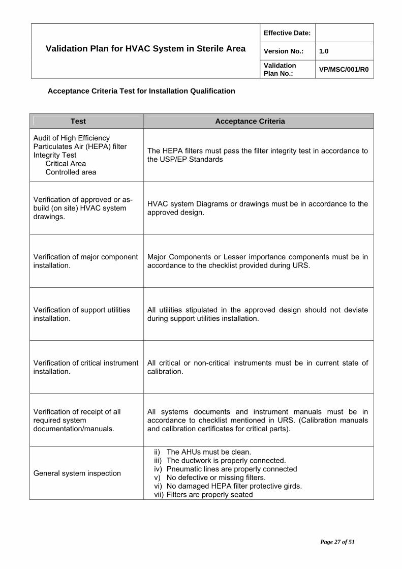
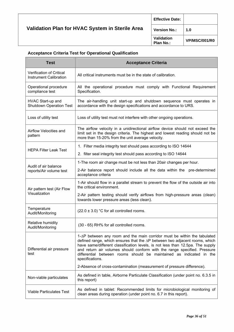
Acceptance Criteria Test for Installation Qualification
Test Acceptance Criteria
Audit of High Efficiency Particulates Air (HEPA) filter Integrity Test
Critical Area Controlled area
The HEPA filters must pass the filter integrity test in accordance to the USP/EP Standards
Verification of approved or as-build (on site) HVAC system drawings.
HVAC system Diagrams or drawings must be in accordance to the approved design.
Verification of major component installation.
Major Components or Lesser importance components must be in accordance to the checklist provided during URS.
Verification of support utilities installation.
All utilities stipulated in the approved design should not deviate during support utilities installation.
Verification of critical instrument installation.
All critical or non-critical instruments must be in current state of calibration.
Verification of receipt of all required system documentation/manuals.
All systems documents and instrument manuals must be in accordance to checklist mentioned in URS. (Calibration manuals and calibration certificates for critical parts).
General system inspection
ii) The AHUs must be clean. iii) The ductwork is properly connected. iv) Pneumatic lines are properly connected v) No defective or missing filters. vi) No damaged HEPA filter protective girds. vii) Filters are properly seated

Effective Date:
Version No.: 1.0 Validation Plan for HVAC System in Sterile Area
Validation Plan No.:
VP/MSC/001/R0
Page 28 of 51
14. Operational Qualification
The OQ is to verify that the specified components of the HVAC system operates as specified and are in agreement with the acceptance criteria and critical systems.
The HVAC system components described in the final design and specifications or authorized changes to the design or specification needs to be qualified to demonstrate their adequate operation. In general, the Operation Qualification scope is to test the individual components of the system such as air-handling unit, ductwork, blowers and others.
Operational Qualification (OQ) protocol No OQP\VD\01\R00 shall be generated; the following qualification tests will be included in the OQ protocol and protocol must be prepared according to SOP-VD-011.
The final performance (i.e. performance qualification) of the system in terms of environmental quality, such as temperature, humidity airborne cleanliness (viable and non-viable), can be assessed only under dynamic conditions whether real or simulated and when the other components of the environmental control system are in place.
Prerequisites: The following list of actions must be completed prior to the beginning of execution of operation qualification protocol, with reference to the validation master plan:
Installation qualification must be completed.
All critical punch-list items from IQ must have been resolved and completed.
All related SOP’s for operation and maintenance of HVAC must have been approved.
Training in pertinent SOP’s for operation of HVAC & sterile area facility must be completed and documented from all concern departments and persons.
The following qualification activities for the OQ must be performed. Successful qualification execution of the activities listed will satisfy the OQ effort for HVAC system.
i. Verification Of Critical Instrument Calibration.
i.1 Instrument that are used to operational decisions for the HVAC system or which provide data that is recorded as part of production or maintenance records, are considered to be as critical instruments. Critical instruments should be verified to be in a current state of calibration. Critical instrument for HVAC system may include:
i.1.1. Pressure gauges (including differential pressure (ΔP) gauges).
i.1.2. Pressure sensor/transmitter/display systems (including ΔP).
i.1.3. Thermometers.
i.1.4. Temperature sensor/transmitter/display systems.
i.1.5. Relative humidity (RH) sensor/transmitter/display systems.
i.1.6. Flow meters (air and liquid)
i.1.7. Data loggers/Recorders.
Effective Date:
Version No.: 1.0 Validation Plan for HVAC System in Sterile Area
Validation Plan No.:
VP/MSC/001/R0
Page 29 of 51
ii. Operational Procedure Compliance Test.
ii.1 A final draft or higher standard operating procedure (SOP) for the operation of the equipment comprising the HVAC system should be verified to be available. (Examples of the SOPs that will be needed):
ii.1.1. SOP # XXX -001 : Operation and Maintenance of the Air Handing Unit
ii.1.2. SOP #XXX -002 : Calibration Procedure of Temperature Probe
ii.1.3. SOP # XXX -003 : Calibration Procedure of Humidity Probe
ii.1.4. SOP # XXX -004 : Calibration Procedure of Static Pressure Probe
ii.2 Personnel operating the system or its individual components during OQ execution should be verified and to have been trained to the referenced SOP(s).
ii.3 SOP availability and operator training should be documented in the protocol test data sheets for this section.
ii.4 Scrutiny of SOP and training of personnel is essentially required in order to assure the availability of written operating procedures that can be verified to complete and accurate, or can be highlighted to make them changes during normal function and/or cycle testing and which can be finalized and approved prior to Performance Qualification (PQ) execution.
ii.5 Operational procedure ensures that the outcome of the individual OQ tests are not distorted by operating the system in a manner that differs significantly from the intended methodology during standard operation.
iii. HVAC start-up and shutdown operation test.
iii.1 To test the start-up and shutdown sequence of the air handling units are as controlled by the controlled system.
iii.2 The testing procedure is designed as a function of the control system. The protocol should outline the sequence to be followed and the devices that intervene in the system.
iii.3 Start-up and shutdown sequence must be recorded, which may provide additional comments or description or unexpected test results.
iii.4 The air-handling unit start-up and shutdown sequence must operates in accordance with the design specifications and accordance to the predetermined limit accordance to URS.
iv. Loss of Utility Test.
iv.1 HVAC system response to the loss of support utilities should be investigated.
iv.2 Response to the loss of electrical power must be tested in all cases, which should include retention of critical data as well as equipment/system response.
iv.3 Equipment/System responses to the loss of other utilities should be documented to ensure that proper protection is provided in the equipment/system design.
iv.4 Loss of electrical power must not result in loss of critical parameters data.

Effective Date:
Version No.: 1.0 Validation Plan for HVAC System in Sterile Area
Validation Plan No.:
VP/MSC/001/R0
Page 30 of 51
iv.5 Equipment/system behavior upon loss or upon resumption of a given utility must be in accordance with available documentation.
iv.6 HVAC systems utility may supply multiple areas; it is very critical that execution will not interfere with other ongoing operations. Support utilities for HVAC systems include:
iv.6.1. Electrical Power
iv.6.2. Clean Steam
iv.6.3. Compressed Air
iv.6.4. Hot/Cold water (for heat exchange)
iv.6.5. Chilled water and glycol (for heat exchange)
v. Airflow velocities and patterns
v.1 In a unidirectional airflow area, usually over a sterile product filling lines, it is important that the air flowing through the critical area has a velocity which is sufficient to produce unidirectional flow and to sweep particulate matter away from the process.
v.2 Airflow velocity should be determined for each HEPA filter, as the average of multiple measures taken at various locations across a plane parallel to and not more than 6inches from filter face.
vi. Clean Room HEPA Filter leak test.
vi.1 HEPA filters shall be replaced after five or ten years, as applicable, from the date of original certification at a DOE filter test facility, if the manufacturing date is not available. HEPA filter systems are designed and installed so the system can be quantitatively leak tested.
vi.2 The injection port and sampling ports must be of sufficient size (nominal ½ inch in diameter) for the insertion of the output line from the aerosol generator or photometer probe.
vi.3 Filter leak test should be performed according to the test procedure as per ISO 14644 which will confirm the filter media and filter seal integrity.
vii. Audit of Air Balance reports.
vii.1 Airflow from AHU to each individual supply air location within the area must be adjusted to within specified tolerances of design flow. This is necessary to achieve proper airflow patterns within the area serviced by the system.
vii.2 Air change in the room must be not less than 20air changes per hour.
vii.3 The return airflow to the AHU must also be adjusted in order to produce the specified pressure differential between individual areas served by the system and adjacent areas.
vii.4 The air balance reports should be reviewed for the following:

Effective Date:
Version No.: 1.0 Validation Plan for HVAC System in Sterile Area
Validation Plan No.:
VP/MSC/001/R0
Page 31 of 51
vii.4.1. SOP for Availability of air balancing procedures.
vii.4.2. Conformance of post-balanced airflow to design.
vii.4.3. Availability of calibration certificate for instruments used during balancing.
vii.4.4. Conformance of static pressures throughout the system to design.
vii.4.5. Room air changes rates.
vii.4.6. Room/area differential pressures.
vii.4.7. Test technician qualifications.
viii. Air pattern Test (Airflow visualization)
viii.1 It is important (Unidirectional flow area) that air flows through the critical area in a smooth pattern without disturbances or eddies which would prevent particulate matter from being swept out of the area by the airflow or cause less clean air to be brought into the cleaner area.
viii.2 Air pattern testing shall be conducted in critical rooms/areas to demonstrate airflow patterns from HEPA through areas/levels of product exposure.
viii.3 Air pattern testing shall also be designed to verify airflows from high-pressure areas (clean) towards lower pressure areas (less clean).
viii.4 All air patterns shall be verified by visually observing airflow with smoke sticks, vapor generators, or other suitable means.
viii.5 Air pattern testing must be recorded via videotaping.
viii.6 Airflow pattern testing should be done in both static and dynamic conditions.
viii.7 Influence of personnel on the airflow pattern during normal operations (sterile filling machine set-up, aseptic connection of sterile transfer lines and interventions) should be included in the studies.
viii.8 An audit may be performed if the documentation for air pattern testing is available and complete. If the documentation is found not satisfactory then the “test” procedure must be performed.
ix. Temperature and Relative Humidity Monitoring
ix.1 Temperature and relative humidity (RH) within the rooms/areas served by the HVAC system is controlled for personnel comfort and process interactions (i.e. too low an RH contributes to static formation; too high may hinder drying steps).
ix.2 Temperature and RH testing should be performed to verify the ability of the HVAC system to control and maintain these parameters in all rooms and areas.
ix.3 Temperature and relative humidity measurements shall be taken in each of the rooms or areas with the environment in an at-rest condition and operational conditions.
ix.4 The temperature and RH measurements shall be collected in each room or area over a twenty-four (24) hour period using independent calibrated measuring devices.
Effective Date:
Version No.: 1.0 Validation Plan for HVAC System in Sterile Area
Validation Plan No.:
VP/MSC/001/R0
Page 32 of 51
ix.5 Measurement must be taken in the four corners and the approximate center of each room or area at a height of approximately 3feet from the floor.
ix.6 Measurement must be performed at least once in each of three consecutive eight-hour time periods.
ix.7 Control system temperature and RH readings should be recorded for each room simultaneously with taking the independent measurements.
ix.8 Available control system temperature and RH archives for the test period should be attached to the protocol.
ix.9 Outside temperature and humidity should also be measured and recorded once for each set of measurements.
ix.10 An audit may be performed if the documentation for Temperature and Relative humidity monitoring is available and complete. If documentation is found not be satisfactory then the “Test” procedure must be performed.
x. Clean room pressurization test (also differential pressures)
x.1 To maintain air quality in critical and controlled areas, it is important that any airflow that occurs between adjacent areas, which have different classification levels, must be from the cleaner area to the less clean area (i.e. from a class 5 area to a class 8 area). This is accomplished by maintaining the air pressure in the cleaner area at a slightly higher level than an air pressure in the less clean area.
x.2 Airflow direction (i.e. in some solid dosage facilities) is designed to create conditions that contain product and minimize cross contamination. This is accomplished by maintaining the air pressure in a common area at a slightly higher or lower level than the air pressure in the adjacent areas of different classifications or cleanliness level (same classification).
x.3 Differential pressure/airflow directional testing shall be conducted to verify the ability of the HVAC system to maintain plant pressurization (positive and negative) between adjacent areas as per the design specifications. This monitoring should be performed routinely and action level should be established in the monitoring program.
x.4 Differential pressure readings/measurements should be recorded using existing, (calibrated) installed system instrumentation. In the absence of such instrumentation, an independent calibrated ∆P gauge or inclined manometer with an appropriate range may be used. The recording of differential pressure measurements shall be conducted once a day for three (3) days in order to demonstrate stability.
x.5 An audit may be performed if the documentation for the Differential Air Pressure and Direction Test is available and complete. If documentation is found not satisfactory then the “Test” procedure must be performed.
x.6 ∆P between any room and the main corridor must be within the tabulated defined range, which ensures that the ∆P between two adjacent rooms, which have same/different classification levels, is not less than 12.5pa. The supply and return air volumes should conform with the range specified. Pressure differential between rooms should be maintained as indicated in the specifications
Effective Date:
Version No.: 1.0 Validation Plan for HVAC System in Sterile Area
Validation Plan No.:
VP/MSC/001/R0
Page 33 of 51
xi. Clean room non-viable particulate count test
xi.1 The non-viable particulate test shall be performed to verify the effectiveness of the environmental filters in minimizing and in effectively removing non-viable particulates from critical and controlled areas, which may be present.
xi.2 Non-viable particulate samples shall be taken in each room or area in “at-rest” conditions.
xi.3 Non-viable particulate samples shall be taken using an independent calibrated particle sampler and recording instrument.
xi.4 Each sample location within the room/area shall be sampled to determine the count of particulates. The number of sample locations must be determined based on the floor area according to ISO standard 14644-1 (Annex B – Point no. B.4 – Sampling) and the area classification.
xi.5 Limits are as defined in table, Airborne Particulate Classification (under point no. 6.3.5 in this report)
xii. Clean room viable particulate count test
xii.1 The viable particulate test shall be performed to monitor the viable particulates, which may be present in critical and controlled areas, and to determine the microbial quality of the air being supplied to each room or area.
xii.2 Viable particulate samples must be taken in each room in normal operating conditions (machinery in use and normal complement of operators present).
xii.3 Sampling must be performed for duration sufficient to sample each room during normal production.
xii.4 Each room must be sampled a minimum of once per shift per day, when the room is in production (operational condition).
xii.5 Testing should be performed over a time period of seventy-two (72) hours concurrent with the temperature, relative humidity and differential pressure monitoring testing.
xii.6 In the event of no production in a room, a minimum of one (1) sample shall be taken for each location daily.
xii.7 Each room must have not less than two (2) sample locations.
xii.8 As defined in tablet: Recommended limits for microbiological monitoring of clean areas during operation (under point no. 6.7 in this report).
Effective Date:
Version No.: 1.0 Validation Plan for HVAC System in Sterile Area
Validation Plan No.:
VP/MSC/001/R0
Page 34 of 51
xiii. Control, Alarms and Interlocks.
xiii.1 Alarms
xiii.1.1. HVAC systems frequently incorporate safety features such as smoke alarms or noxious fume alarms.
xiii.1.2. HVAC systems frequently include alarms for items such as room pressurization, temperature and relative humidity, which could, if out of specification (OOS), potentially have an adverse effect on product quality.
xiii.1.3. Safety system features should be tested in order to ensure personnel and system safety.
xiii.1.4. Critical alarms should be tested for proper operation to ensure that they are functional and will provide warning before any system, product quality, or personnel safety is compromised.
xiii.1.5. HVAC system alarms are listed below:
xiii.1.5.1. Smoke detector operation.
xiii.1.5.2. Plenum pressure alarms
xiii.1.5.3. Room door interlocks
xiii.1.5.4. Filter ∆P alarms.
xiii.1.5.5. Room pressure/∆P alarms
xiii.1.5.6. Temperature alarms
xiii.1.5.7. Humidity alarms.
xiii.2 Interlocking:
xiii.2.1. Interlocks may be mechanical or part of the electrical/mechanical control system.
xiii.2.2. Some interlocks are not associated with loops and may serve to either act as preventive measures (turn the pump off before the tank is empty preventing pump cavitation) or to initiate an activity (an exhaust fan automatically starts when the supply fan is started).
xiii.2.3. Interlock testing may be performed as part of normal sequence of operation testing or as a separate activity.
xiii.2.4. Like sequence testing, interlock testing involves the forcing either through simulation or through ‘expected’ operating conditions of inputs and verifying that the interlock action operations as specified.
xiii.2.5. Door interlocking (X door is opened when Y door is closed, similarly, Y door is opened when X door is closed) system creates to keep the area intact and prevent from the contamination.

Effective Date:
Version No.: 1.0 Validation Plan for HVAC System in Sterile Area
Validation Plan No.:
VP/MSC/001/R0
Page 35 of 51
xiv. Power Fail and Recovery test.
xiv.1 Verification must be performed that control system can maintain the components of the air-handling unit within the specified range after the power failure (within 15minutes).
xiv.2 Testing operation objective for air handling pneumatic, electric or electronic control system during a power fail and recovery cycle.
xiv.3 Testing procedure must be designed as a function of the system tested. Because the power fail and recovery test is a major system test greatly exercised to prevent damage to personnel or equipment.
xiv.4 The test should be designed in accordance with HVAC and controls design engineers. Therefore, the following must be concluded:
xiv.4.1. Proceed to simulate the failure.
xiv.4.2. Bring the system to complete stop.
xiv.4.3. Wait for the required time before restart to prevent mechanical or electrical (overcharge) damage to the system.
xiv.5 After completion of the foregoing three steps, restart the system.
xiv.6 Recording of the time that it takes for the system to reestablish the approved conditions.
xiv.7 Record the monitored environmental parameters (air volume, pressure differential, temperature, humidity).
xiv.8 The data must be compared that had already been acceptable for the environment tested.
xiv.9 Particular attention must be given to pressure differentials as the best indicator of the system capability to regain control.
xiv.10 Schedule of tests to be performed on regular basis to continuing compliance of system.
Effective Date:
Version No.: 1.0 Validation Plan for HVAC System in Sterile Area
Validation Plan No.:
VP/MSC/001/R0
Page 36 of 51
Acceptance Criteria Test for Operational Qualification
Test Acceptance Criteria
Verification of Critical Instrument Calibration
All critical instruments must be in the state of calibration.
Operational procedure compliance test
All the operational procedure must comply with Functional Requirement Specification.
HVAC Start-up and Shutdown Operation Test
The air-handling unit start-up and shutdown sequence must operates in accordance with the design specifications and accordance to URS.
Loss of utility test Loss of utility test must not interfere with other ongoing operations.
Airflow Velocities and pattern
The airflow velocity in a unidirectional airflow device should not exceed the limit set in the design criteria. The highest and lowest reading should not be more than 15-20% from the unit average velocity.
HEPA Filter Leak Test 1. Filter media integrity test should pass according to ISO 14644
2. filter seal integrity test should pass according to ISO 14644
Audit of air balance reports/Air volume test
1-The room air change must be not less than 20air changes per hour.
2-Air balance report should include all the data within the pre-determined acceptance criteria
Air pattern test (Air Flow Visualization
1-Air should flow in a parallel stream to prevent the flow of the outside air into the critical environment.
2-Air pattern testing should verify airflows from high-pressure areas (clean) towards lower pressure areas (less clean).
Temperature Audit/Monitoring
(22.0 ± 3.0) °C for all controlled rooms.
Relative humidity Audit/Monitoring
(30 - 65) RH% for all controlled rooms.
Differential air pressure test
1-∆P between any room and the main corridor must be within the tabulated defined range, which ensures that the ∆P between two adjacent rooms, which have same/different classification levels, is not less than 12.5pa. The supply and return air volumes should conform with the range specified. Pressure differential between rooms should be maintained as indicated in the specifications.
2-Absence of cross-contamination (measurement of pressure difference).
Non-viable particulates As defined in table, Airborne Particulate Classification (under point no. 6.3.5 in this report)
Viable Particulates Test As defined in tablet: Recommended limits for microbiological monitoring of clean areas during operation (under point no. 6.7 in this report).
Effective Date:
Version No.: 1.0 Validation Plan for HVAC System in Sterile Area
Validation Plan No.:
VP/MSC/001/R0
Page 37 of 51
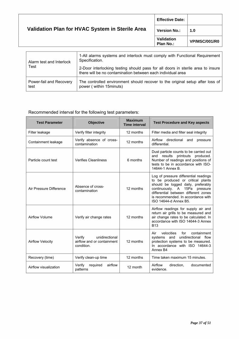
Alarm test and Interlock Test
1-All alarms systems and interlock must comply with Functional Requirement Specification.
2-Door interlocking testing should pass for all doors in sterile area to insure there will be no contamination between each individual area
Power-fail and Recovery test
The controlled environment should recover to the original setup after loss of power ( within 15minuts)
Recommended interval for the following test parameters:
Test Parameter Objective Maximum
Time interval Test Procedure and Key aspects
Filter leakage Verify filter integrity 12 months Filter media and filter seal integrity
Containment leakage Verify absence of cross-contamination
12 months Airflow directional and pressure differential.
Particle count test Verifies Cleanliness 6 months
Dust particle counts to be carried out and results printouts produced. Number of readings and positions of tests to be in accordance with ISO-14644-1 Annex B.
Air Pressure Difference Absence of cross-contamination
12 months
Log of pressure differential readings to be produced or critical plants should be logged daily, preferably continuously. A 15Pa pressure differential between different zones is recommended. In accordance with ISO 14644-d Annex B5.
Airflow Volume Verify air change rates 12 months
Airflow readings for supply air and return air grills to be measured and air change rates to be calculated. In accordance with ISO 14644-3 Annex B13
Airflow Velocity Verify unidirectional airflow and or containment condition.
12 months
Air velocities for containment systems and unidirectional flow protection systems to be measured. In accordance with ISO 14644-3 Annex B4
Recovery (time) Verify clean-up time 12 months Time taken maximum 15 minutes.
Airflow visualization Verify required airflow patterns
12 month Airflow direction, documented evidence.

Effective Date:
Version No.: 1.0 Validation Plan for HVAC System in Sterile Area
Validation Plan No.:
VP/MSC/001/R0
Page 38 of 51
15. Performance Qualification
Performance Qualification is outlined below represents the quality testing performed in the OQ (i.e. viable) but expands the scope to include testing under dynamic conditions. The final and real challenge for the environment control system and HVAC system is represented by the process that must be executed within the areas it is serving. Upon determination of the new approved conditions, if needed, changes to the system are to be executed and revalidated before proceeding to the performance qualification.
Performance Qualification (PQ) protocol No PQP\VD\01\R00 shall be generated; the following qualification tests will be included in the PQ protocol and protocol must be prepared according to SOP-VD-012.
This section describes the various types of monitoring that would be performed to adequately qualify the operating environment for processing.
i. Performance Qualification must be performed on the facility in three different stages that are
i.1 “As-built” (No equipment, no personnel).
i.2 “At-rest” (equipment but no operations and no personnel)
i.3 “Operational” (With personnel, equipment operations)
Consistent results must be obtained which should be within specified limits for 20consecutive working days for each of the three stages (as built, at rest and operation).
ii. Verification of Performance Qualification prerequisites
ii.1 The success of the system to control the level of viable and non-viable particulate levels as well as its ability to regulate temperature and relative humidity conditions depends not only on the system performance, but on outside factors such as personnel training, room sanitization, and system maintenance.
ii.2 Method for sanitization procedures, supporting utilities and personnel should be qualified/trained before the initiation of the PQ as well as procedures for sampling, operation and maintenance should be in place.
ii.3 By having these prerequisites completed before the HVAC system PQ and environmental monitoring program, the success for PQ is greatly extended and it is much easier to isolate attributable causes in the event of PQ failure.
ii.4 The prerequisites for the HVAC system PQ can be summarized below:
ii.4.1. HVAC: IQ and OQ complete.
ii.4.2. Utilities: IQ, OQ, PQ and including SOPs for compressed air and steam.
Effective Date:
Version No.: 1.0 Validation Plan for HVAC System in Sterile Area
Validation Plan No.:
VP/MSC/001/R0
Page 39 of 51
ii.4.3. Personnel: SOPs and training documentation for equipment operation, room sanitization gowning and environment monitoring. Training in pertinent SOP’s for HVAC & sterile area facility & all related operation and maintenance machines are completed and documented from all concern departments and persons
ii.4.4. Standard Operating System (SOP) must be development and approved before performance qualification (PQ) tests are executed for following:
a. Environmental Monitoring. b. System Operation c. System Maintenance.
ii.5 All critical punch-list items from IQ and OQ must be cleared and resolved.
iii. Temperature – Humidity Control Test - Dynamic Condition
iii.1 To demonstrate the ability of the HVAC system to control temperature and humidity during operating conditions. This test must be executed while the process or operation are simulated or executed.
iii.2 The Temperature-humidity control test provides verification of temperature and humidity under dynamic conditions, as well as indicating that the system is capable of maintaining the design conditions. It also provides a good basis for determination of the general status of the system, for its malfunction can be used as diagnostic of the inadequate operation of the HVAC.
iii.3 Seasonal conditions of temperature and humidity may vary with the system design and the amount of external non-conditioned air supplied to the air-handling units serving the controlled environment. Sporadically, seasonal variations can be simulated during validation conditions.
iv. Differential Air Pressure and Direction Test – Dynamic Conditions
iv.1 In order to maintain air quality in critical and controlled areas, it is important that any airflow that occurs between adjacent areas which have different classification levels must be from the cleaner area to the less clean area (i.e., from a Class 5 area to a Class 7area). This is accomplished by maintaining the air pressure in the cleaner area at a slightly higher level than the air pressure in the less clean area.
iv.2 In s solid dosage facilities, airflow direction is designed to create conditions that contain product and minimize cross contamination. This is accomplished by maintaining the air pressure in the common area at a slightly higher level than the air pressure in the processing area.
iv.3 US guidelines require a differential pressure of 0.05” water column between rooms of different air cleanliness. EU guidelines require a differential pressure 10-15 Pascals.

Effective Date:
Version No.: 1.0 Validation Plan for HVAC System in Sterile Area
Validation Plan No.:
VP/MSC/001/R0
Page 40 of 51
iv.4 Differential Pressure/Airflow Directional Testing shall be conducted to verify the ability of the HVAC System to maintain plant pressurization positive between adjacent areas while in a normal operating condition (machinery in use and normal complement of operators present). This monitoring should be performed routinely and action levels should be established in the monitoring program per the requirements of ISO standard 14644-1 and 2.
iv.5 Differential pressure readings/measurements should be recorded using existing, (calibrated) installed system instrumentation. In the absence of such instrumentation, an independent calibrated dP gauge or inclined manometer with an appropriate range may be used. The recording of differential pressure measurements shall be conducted once a day for three (20) working days in order to demonstrate stability.
v. Air Cleanliness Test
v.1 Air Cleanliness test must be performed in order to determine that the complete as-built, operational facility meets the air cleanliness requirements specified in the user requirement specification.
v.2 Airborne concentrations are measured with white light, laser, or condensation nuclei particle counters.
v.3 Air cleanliness classification for controlled environments must be based on the concentration of particles of a specific size per unit of volume.
v.4 Sampling location and sample size must be set cautiously.
v.5 A sample should be taken at the fill point at a distance not exceeding 30cm (1ft3) from the point of exposure and a sample volume of 1ft3.
v.6 The table demonstrates the limit and range of air quality for every parameters that are performed in accordance with standard establishment
Parameters Limit/Range Reference TSI Instrument
Temperature 22 3C ASHRAE standard 55-
1992
Q-Trak Plus IAQ-Calc TH-Calc VelociCalc Plus
Relative humidity 30% to 65% ASHRAE Standard 55-
1992 Q-Trak Plus IAQ-Calc
Air movement 80ft/s or 0.25m/s WHO
VelocioCalc VelociCalc Plus VelociaCeck DP-Calc AccuBalance
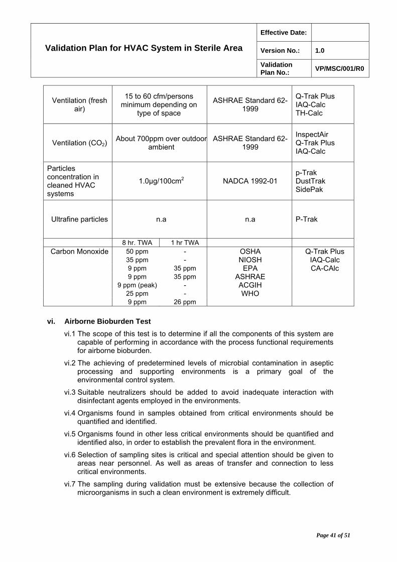
Effective Date:
Version No.: 1.0 Validation Plan for HVAC System in Sterile Area
Validation Plan No.:
VP/MSC/001/R0
Page 41 of 51
Ventilation (fresh air)
15 to 60 cfm/persons minimum depending on
type of space
ASHRAE Standard 62-1999
Q-Trak Plus IAQ-Calc TH-Calc
Ventilation (CO2) About 700ppm over outdoor
ambient ASHRAE Standard 62-
1999
InspectAir Q-Trak Plus IAQ-Calc
Particles concentration in cleaned HVAC systems
1.0µg/100cm2 NADCA 1992-01 p-Trak DustTrak SidePak
Ultrafine particles n.a n.a P-Trak
8 hr. TWA 1 hr TWA Carbon Monoxide 50 ppm - OSHA Q-Trak Plus
35 ppm - NIOSH IAQ-Calc 9 ppm 35 ppm EPA CA-CAlc 9 ppm 35 ppm ASHRAE 9 ppm (peak) - ACGIH 25 ppm - WHO 9 ppm 26 ppm
vi. Airborne Bioburden Test
vi.1 The scope of this test is to determine if all the components of this system are capable of performing in accordance with the process functional requirements for airborne bioburden.
vi.2 The achieving of predetermined levels of microbial contamination in aseptic processing and supporting environments is a primary goal of the environmental control system.
vi.3 Suitable neutralizers should be added to avoid inadequate interaction with disinfectant agents employed in the environments.
vi.4 Organisms found in samples obtained from critical environments should be quantified and identified.
vi.5 Organisms found in other less critical environments should be quantified and identified also, in order to establish the prevalent flora in the environment.
vi.6 Selection of sampling sites is critical and special attention should be given to areas near personnel. As well as areas of transfer and connection to less critical environments.
vi.7 The sampling during validation must be extensive because the collection of microorganisms in such a clean environment is extremely difficult.
Effective Date:
Version No.: 1.0 Validation Plan for HVAC System in Sterile Area
Validation Plan No.:
VP/MSC/001/R0
Page 42 of 51
vi.8 Tests are performed to show that the air quality meets the specifications for particulates, temperature, humidity, microbial counts, lighting levels, etc. for the specification and classification of each room.
vii. Surface Bioburden Test
vii.1 The final evaluation of cleaning and disinfection must be performed in order to determine the bioburden content on the surface either in the facility or on particular equipment and device.
vii.2 The use of adequate cleaning and disinfection to achieve a level of quality environmental.
vii.3 As part of validation task, it is essential to determine that the effectiveness of this procedure is reflected at the rest of environment is being qualified.
vii.4 Evaluation of the surface bioburden test in pre-cleaning condition must be performed.
vii.5 Testing after the cleaning and disinfection in a repetitive approach, this must ensure to establish of these methods to perform such activity.
vii.6 Limits for surface bioburden test must be as follows:
vii.6.1. The limit for critical environment must be not more than 1CFU/12.9cm2 or 2 in2 (FDA Aseptic Processing guidelines).
vii.6.2. Similarly, other environments that are adjacent to critical environments: 5/12.9 cm2 or 2in2.
vii.6.3. For controlled environments: 20/12.9cm2 or 2in2.
viii. Non-Viable Particulate Testing (Critical and Controlled Rooms/Areas Only) – Dynamic Conditions
viii.1 Non-viable Particulate Testing shall be performed to verify the effectiveness of the Environmental Filters in minimizing and in effectively removing non-viable particulates, which may be present in critical and controlled areas.
viii.2 Testing shall be performed in accordance with the current U.S. FDA Guideline to Aseptic Processing and ISO Standard 14644-1
viii.3 Non-viable particulate samples shall be taken in each room or area in a normal operating condition (machinery in use and normal complement of operators present).
viii.4 Non-viable particulate samples shall be taken using an independent calibrated particle sampler and recording instrument, or may be taken using a qualified Particulate Counting System (PCS), if available.
viii.5 Each sample location within the room/area shall be sampled to determine the count of particulates. The number of sample locations shall be determined based on the floor area and the area classification.
Effective Date:
Version No.: 1.0 Validation Plan for HVAC System in Sterile Area
Validation Plan No.:
VP/MSC/001/R0
Page 43 of 51
viii.6 Limits:
Controlled Areas: The EU guidelines require these areas to be Class C. Air in controlled areas is generally of acceptable particulate quality if it has a per-cubic-meter particle count of not more than 3,520,000 in a size range of 0.5 micron and larger (Class 8) when measured in the vicinity of the exposed articles during periods of activity. There is also a requirement to have less than 29,000 particles/m3 of 5.0 m and larger in the “in operation” state. To meet EU requirements both 0.5 and 5.0 m particle sizes must be counted.
Critical Areas: The EU guideline requires these areas to be Class A (corresponding to US Class 5 unidirectional flow), with the background of Class B. Air in the immediate proximity of exposed sterilized containers/closures and filling/closing operations is of acceptable particulate quality when it has a per-cubic-meter particle count of no more than 3,520 in a size range of 0.5 micron and larger (corresponds to US Class 5) when measured not more than one foot away from the work site, and upstream of the airflow, during filling/closing operations. It is accepted that sometimes conformity with particle counts may not be met at point of fill due to generation of particles or droplets from the product itself. Class B under dynamic conditions is of acceptable particulate quality when it has a per-cubic-meter particle count of no more than 352,000 of 0.5 micron and larger. The 5.0 m limits are 20 particles/m3 for Grade A and 2,900 particles/m3 for Grade B in operation.
ix. Viable Particulates Test (Critical and Controlled Rooms/Areas Only) – Dynamic Conditions
ix.1 The Viable Particulates Test shall be performed to monitor the viable particulates, which may be present in critical and controlled areas, and to determine the microbial quality of the air being supplied to each room or area.
ix.2 Viable particulate samples shall be taken in each room in a normal operating condition (machinery in use and normal complement of operators present).
ix.3 Sampling shall be conducted in accordance with the company’s procedures. Sampling shall be performed for duration sufficient to sample each room during normal production.
ix.4 Each room shall be sampled a minimum of two (2) times per day, when the room is in production (operational condition).
ix.5 Testing should be performed over a time period of 20 consecutive days concurrent with the temperature, relative humidity, and differential pressure monitoring testing. In the event of no production in a room, a minimum of one (1) sample shall be taken for each location daily.
Effective Date:
Version No.: 1.0 Validation Plan for HVAC System in Sterile Area
Validation Plan No.:
VP/MSC/001/R0
Page 44 of 51
ix.6 Each room shall have no less than two (2) sample locations.
Controlled Areas: EU guidelines require a maximum average viable organism count of 100/M3 (2.8/Ft3).
Critical Areas: EU guidelines a maximum average viable organism count of < 1.0/m3 (0.03/Ft3), with a background maximum average viable organism count of /m3 (0.14/Ft3).
For testing to EU standards the average of the last 10 samples taken from a sampling site should be compared to the values given above.

Effective Date:
Version No.: 1.0 Validation Plan for HVAC System in Sterile Area
Validation Plan No.:
VP/MSC/001/R0
Page 45 of 51
Acceptance Criteria Test for Performance Qualification
Test Acceptance Criteria
Verification of Performance Qualification prerequisites
All actions must be performed before starting execution of performance qualification activities.
Temperature – Humidity Control test
1. The specified temperature range must not be more than 22 3C.
2. The specified relative humidity range must not be more than 30-65% in aseptic processing areas. Unless otherwise specified by the process requirements.
Differential Air Pressure and Direction Test – Dynamic Conditions
1-∆P between any room and the main corridor must be within the tabulated defined range, which ensures that the ∆P between two adjacent rooms, which have same/different classification levels, is not less than 12.5pa. The supply and return air volumes should conform with the range specified. Pressure differential between rooms should be maintained as indicated in the specifications.
2-Absence of cross-contamination (measurement of pressure difference).
Air Cleanliness Test
1. Critical Environment: The particle concentration under dynamic conditions should not be more than 3.5 particles of 0.5µm and larger per cubic meter (100particles of 0.5µm and larger per cubic feet).
2. Other Environments: Typically a tenfold gradient must be used from critical to less critical environments (ex. 1,000 for environment adjacent to critical environment 10,000 for those adjacent to it.)
Airborne Bioburden Test
1. Critical Environments: Not more than 1CFU/m3 or 0.03 CFU/ft3.
2. Typical for other environments: Adjacent to critical environment 5/m3 or 0.15/ft3.
3. Controlled Environments: 87/m3 or 2.5/ft3.
Surface Bioburden Test
1. Critical Environments: Not more than 1 CFU/12.9 cm2 or 2in2.
2. Typical for other environments: adjacent to critical environments: 5/12.9 cm2 or 2in2.
3. Controlled Environments: 20/12.9cm2 or 2in2.
Non-Viable Particulate Testing (Critical and Controlled Rooms/Areas Only) – Dynamic Conditions
As defined in table, Airborne Particulate Classification (under point no. 6.3.5 in this report)
Viable Particulates Test (Critical and Controlled Rooms/Areas Only) – Dynamic Conditions
As defined in tablet: Recommended limits for microbiological monitoring of clean areas during operation (under point no. 6.7 in this report).

Effective Date:
Version No.: 1.0 Validation Plan for HVAC System in Sterile Area
Validation Plan No.:
VP/MSC/001/R0
Page 46 of 51
16. Planning and Cost: All planning and cost schedule is performed in Microsoft Project
(Windows based) 2003 software. The total cost of this HVAC validation plan project is USD. 38,000/-.
16.1 The reports are attached for immediate reference (Attachment no. 05).
17. Discrepancy/ Justification And Corrective Action
17.1 If deviations are observed while performing the qualification tests, generate deviation report as outlined in attachment no. 03/R0. Generate deviation report individually for each test that failed to meet the acceptance criteria.
17.2 If deviations are acceptable, write justification(s) for acceptance and impact of the function and complete the deviation report.
18. Validation Plan Report
18.1 Prepare a validation plan report as outlined in attachment no. 04/R0. The validation plan report should include date study initiated, date completed, observations made, problems encountered, and completeness of information collected, summary of deviation report, sample data if appropriate, other information relevant to the study, and conclusions on the validity of the qualification.
18.2 After completion of the report in all aspects submit the report to QA for review and approval.
19. Modification/ Change Control During Qualification: For Direct Impact systems, certain changes may affect qualification plans, tests, or documentation. Changes should be assessed for potential impact and communicated to appropriate team members. Agreement should be obtained from the approval signatories before implementation of the change as per SOP-XXX-: Change Control. An assessment will be made before any modification or change to the system to determine if revalidation is required or not required. The QA should review and input into changes when one or more of the following conditions occur.
19.1 The change alters the impact assessment (i.e. it causes a formerly “Indirect Impact” system to now be a “Direct Impact”, system or vice-versa.)
19.2 There is a fundamental Change in the design concept.
19.3 There is a change in the User Requirements Brief or Requirement Specifications.

Effective Date:
Version No.: 1.0 Validation Plan for HVAC System in Sterile Area
Validation Plan No.:
VP/MSC/001/R0
Page 47 of 51
20. Re-qualification: Re-qualification can be performed as the result of an event-based or time based assessment as defined in the Validation Master Plan (VMP), in both cases of time or event based circumstances; the system owner, Quality Assurance, Engineering and Validation Departments will be responsible for assessing the level of the revalidation requirement. Normally the requalification for IQ,OQ and PQ can be summarized below:
20.1 IQ –Requalification
20.1.1. Modification in the HVAC system
20.1.2. Replacement of major component
20.1.3. Relocation of any component of the HVAC system
20.2 OQ & PQ Requalification
20.2.1. Modification in the HVAC system
20.2.2. Replacement of major component
20.2.3. Relocation of any component of the HVAC system
20.2.4. Annual re qualification
20.2.5. Any contamination problem
21. References and Related Records
21.1 ISO standard 14644-1 (Annex B – Point no. B.4 – Sampling) Clean rooms and associated controlled environments
21.2 Validation Master Plan-VMP
21.3 User requirement specification
21.4 Supplier drawing and specification
21.5 Commissioning and Qualification (ISPE/Volume 5)
21.6 WHO Guide for GMP requirements-Part 2 Validation.
21.7 Qualification of HVAC Lab compliance www.labcompliance.com.
21.8 Validation of Pharmaceutical Processes, Second Edition.
21.9 United States Pharmacopoeia 32.
21.10 American society of heating, refrigerating and air conditioning engineers.
21.11 XXX Validation guideline for HVAC.
21.12 WHO validation guideline for HVAC for non sterile product.
21.13 Institute of Environmental sciences (IES). Federal Standard 209E. Airborne
Effective Date:
Version No.: 1.0 Validation Plan for HVAC System in Sterile Area
Validation Plan No.:
VP/MSC/001/R0
Page 48 of 51
Particulate cleanliness classes in clean rooms and clean zones.
22. Definitions: Definitions of terms and abbreviations relating to this validation plan which
are given below:
Abbreviation - Expansion
HVAC : Heating ,ventilation and air conditioning
IQ : Installation Qualification
OQ : Performance Qualification
PQ Performance qualification
SOP : Standard Operating Procedure
FAC Facility
CC : Change Control
GMP Good Manufacturing Practice
QA : Quality Assurance
QC : Quality Control
VMP Validation Master Plan
ACUs Air Handling Units
XXX : XXX Pharmaceutical Manufacturing Company
US FDA United State Food & Drug Administration
USP United State Pharmacopoeia
CFU Colony Forming Unit
SA Sterile Area
VP Validation Plan
GEP Good Engineering Practice
FAT Factory Acceptance Test
HEPA High Efficiency Particulate Air
PI&D’s Piping and instrument Diagrams
23. Glossary

Effective Date:
Version No.: 1.0 Validation Plan for HVAC System in Sterile Area
Validation Plan No.:
VP/MSC/001/R0
Page 49 of 51
23.1 Acceptance criteria: Numerical limits, ranges, or other suitable measures for acceptance of test results.
23.2 Action level (in clean rooms): An established microbial or airborne particle level that, when exceeded, should trigger appropriate investigation and corrective action based on the investigation.
23.3 Alert limits (Environmental Monitoring): Established microbial or particulate levels giving early warning of potential drift from normal operating conditions which are not necessarily grounds for definitive corrective action but which require follow-up investigation.
23.4 Alert limits (media fill): Established levels or numbers of positive media filled units, the cause of which should be investigated, but which are not necessarily grounds for definitive corrective action.
23.5 Aseptic filling: Operation whereby the product is sterilised separately, then filled and packaged using sterilised containers and closures in critical processing zones.
23.6 Aseptic processing facility: A building, or segregated segment of it, containing cleanrooms in which air supply, materials, and equipment are regulated to control microbial and particle contamination.
23.7 Aseptic processing room: A room in which one or more aseptic activities or processes are performed.
23.8 Aseptic manufacturing area: The classified part of a facility that includes the aseptic processing room and ancillary cleanrooms.
23.9 Change control: A formal system by which qualified representatives of appropriate disciplines review proposed or actual changes that might affect a validated status of facilities, systems, equipment or processes. The intent is to determine the need for action that would ensure that the system is maintained in a validated state
23.10 Clean area: An area with defined environmental control of particulate and microbial contamination, constructed and used in such a way as to reduce the introduction, generation and retention of contaminants within the area
23.11 Cleaning Validation: Cleaning validation is documented evidence that an approved cleaning procedure will provide equipment, which is suitable for processing medicinal products.
23.12 Cleanroom: A room designed, maintained, and controlled to prevent particle and microbiological contamination of drug products. Such a room is assigned and reproducibly meets an appropriate air cleanliness classification.
Effective Date:
Version No.: 1.0 Validation Plan for HVAC System in Sterile Area
Validation Plan No.:
VP/MSC/001/R0
Page 50 of 51
23.13 Controlled area: An area constructed and operated in such a manner that some attempt is made to control the introduction of potential contamination (an air supply approximating to grade D may be appropriate), and the consequences of accidental release of living organisms. The level of control exercised should reflect the nature of the organism employed in the process. At a minimum, the area should be maintained at a pressure negative to the immediate external environment and allow for the efficient removal of small quantities of airborne contaminants.
23.14 Installation Qualification (IQ): The documented verification that the facilities, systems and equipment, as installed or modified, comply with the approved design and the manufacturer's recommendations
23.15 Laminar flow: An airflow moving in a single direction and in parallel layers at constant velocity from the beginning to the end of a straight line vector.
23.16 Media fills: Method of evaluating an aseptic process using a microbial growth medium. (Media fills are understood to be synonymous to simulated product fills, broth trials, broth fills etc.).
23.17 Operational Qualification (OQ): The documented verification that the facilities, systems and equipment, as installed or modified, perform as intended throughout the anticipated operating ranges.
23.18 Performance Qualification (PQ): The documented verification that the facilities, systems and equipment, as connected together, can perform effectively and reproducibly, based on the approved process method and product specification.
23.19 Pre-determined acceptance criteria: The criteria assigned, before undertaking testing, to allow evaluation of test results to demonstrate compliance with a test phase of delivery requirement
23.20 Unidirectional flow: An airflow moving in a single direction, in a robust and uniform manner, and at sufficient speed to reproducibly sweep particles away from the critical processing or testing area.
23.21 Validation master plan: A document providing information on the company's validation work programme. It should define details of and timescales for the validation work to be performed. Responsibilities relating to the plan should be stated.
23.22 Validation protocol: A written plan stating how validation will be conducted and defining acceptance criteria. For example, the protocol for a manufacturing process identifies processing equipment, critical process parameters/operating ranges, product characteristics, sampling, test data to be collected, number of validation runs, and acceptable test results.
23.23 Validation report: Document reporting the validation activities, the validation data and the conclusions drawn.
24. History: First Issue
Effective Date:
Version No.: 1.0 Validation Plan for HVAC System in Sterile Area
Validation Plan No.:
VP/MSC/001/R0
Page 51 of 51
25. Attachments
27.1 Attachment No. 01/R0 : HVAC System Diagram
27.2 Attachment No. 02/R0 : Sterile Area Diagram.
27.3 Attachment No. 03/R0 : Discrepancies and corresponding report.
27.4 Attachment No. 04/R0 : Qualification Report.
27.5 Attachment No. 05/R0 : Microsoft Project Reports for HVAC Validation plan.
27.6 Attachment No. 06/R0 : List of Discrepancy (ies).
27.7 Attachment No. 07/R0 : Qualification Notes.
27.8 Attachment No. 08/R0 : Installation Qualification Template.
27.9 Attachment No. 09/R0 : Operational Qualification Template.
27.10 Attachment No. 10/R0 : Performance Qualification Template.
27.11 Attachment No. 11/R0 : Signature Identification.
26. System Qualification Statement And Qualification Summary
26.1 After conclusion of all the verifications, tests and challenges indicated and after complying with the approved specifications and parameters, the system can be considered validated.
26.2 A final report or summary must be prepared for every section and for the overall protocol. Deviations should be noted and explained if approved; the rationale should be included in the final protocol summaries.
26.3 The documents should be verified for completeness, accuracy and compliance with cGMP requirements before its final approval.
26.4 Validation of the environmental control system should serve as a basis for not only approval and commissioning of all the components of the system, but also to establish the basis for routine monitoring.
27. Control of qualification protocol format
27.1 IQ, OQ and PQ validation protocols will be performed in accordance to attachment no. 08, 09 and 10.