Embed Size (px)
Citation preview
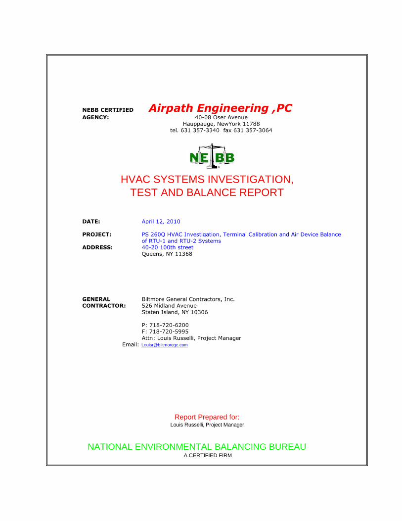
NEBB CERTIFIED Airpath Engineering ,PCAGENCY: 40-08 Oser Avenue
Hauppauge, NewYork 11788tel. 631 357-3340 fax 631 357-3064
DATE: April 12, 2010
PROJECT: PS 260Q HVAC Investigation, Terminal Calibration and Air Device Balanceof RTU-1 and RTU-2 Systems
ADDRESS: 40-20 100th streetQueens, NY 11368
GENERAL Biltmore General Contractors, Inc.CONTRACTOR: 526 Midland Avenue
Staten Island, NY 10306
P: 718-720-6200F: 718-720-5995Attn: Louis Russelli, Project Manager
Email: [email protected]
NATIONAL ENVIRONMENTAL BALANCING BUREAU A CERTIFIED FIRM
HVAC SYSTEMS INVESTIGATION,
TEST AND BALANCE REPORT
Report Prepared for:Louis Russelli, Project Manager

CERTIFIED FIRM
AIRPATH CONT
CONTENTS PAGE
SUMMARY - FIELD REP0RT 1 . 3
CERTIFICATION 1 . 6
INSTRUMENTATION CALIBRATION DATA 1 . 7
AIR APPARATUS TEST REPORT 2 . 1
FPB & VAV TEST REPORTS 3 . 1
RECTANGULAR DUCT TRAVERSE REPORTS APPENDIX
ABBREVIATIONS APPENDIX
DUCTWORK & SUPPLY OUTLET LAYOUT ATTACHMENTS
AND NUMBERED IDENTIFICATION OF
NEW EQUIPMENT
PAGE 1. 2
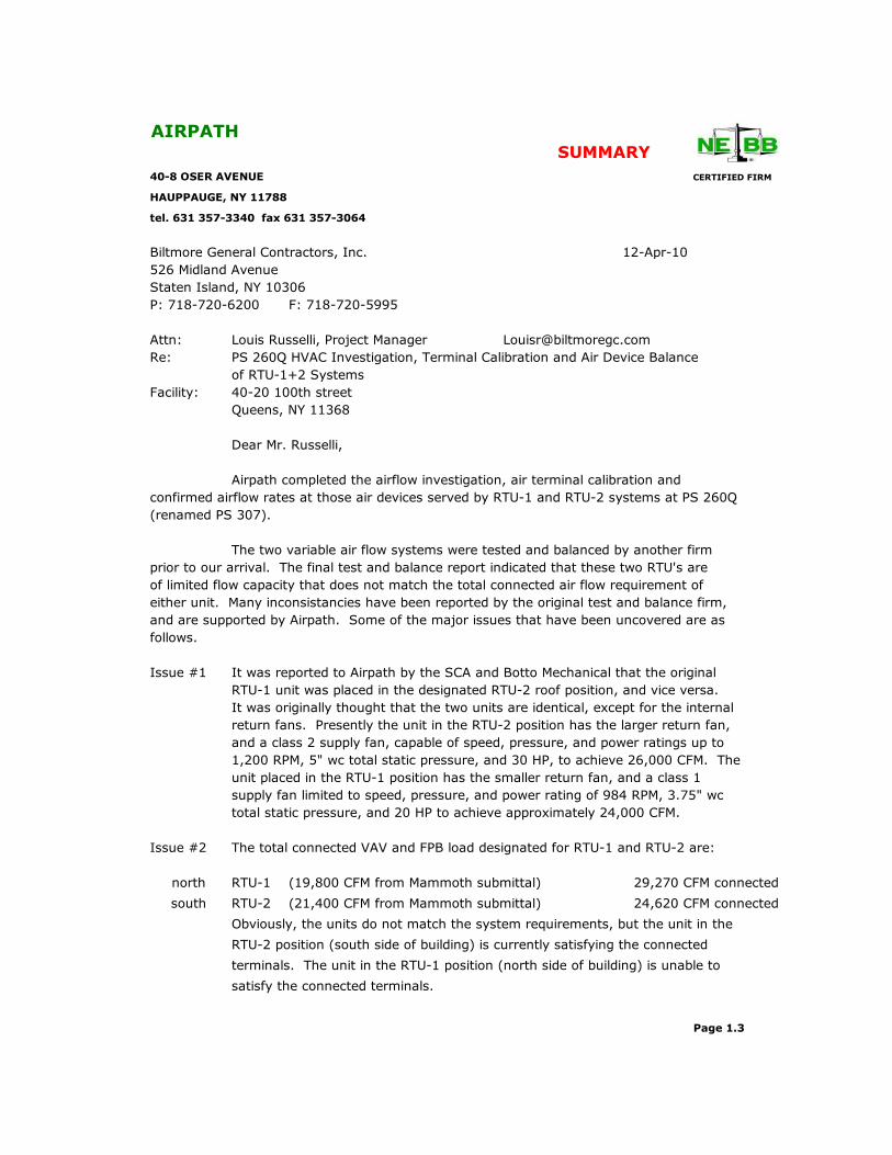
AIRPATHSUMMARY
40-8 OSER AVENUE CERTIFIED FIRM
HAUPPAUGE, NY 11788
tel. 631 357-3340 fax 631 357-3064
Biltmore General Contractors, Inc.
526 Midland Avenue
Staten Island, NY 10306
P: 718-720-6200 F: 718-720-5995
Attn: Louis Russelli, Project Manager [email protected]
Re: PS 260Q HVAC Investigation, Terminal Calibration and Air Device Balance
of RTU-1+2 Systems
Facility: 40-20 100th street
Queens, NY 11368
Dear Mr. Russelli,
Airpath completed the airflow investigation, air terminal calibration and
confirmed airflow rates at those air devices served by RTU-1 and RTU-2 systems at PS 260Q
(renamed PS 307).
The two variable air flow systems were tested and balanced by another firm
prior to our arrival. The final test and balance report indicated that these two RTU's are
of limited flow capacity that does not match the total connected air flow requirement of
either unit. Many inconsistancies have been reported by the original test and balance firm,
and are supported by Airpath. Some of the major issues that have been uncovered are as
follows.
Issue #1 It was reported to Airpath by the SCA and Botto Mechanical that the original
RTU-1 unit was placed in the designated RTU-2 roof position, and vice versa.
It was originally thought that the two units are identical, except for the internal
return fans. Presently the unit in the RTU-2 position has the larger return fan,
and a class 2 supply fan, capable of speed, pressure, and power ratings up to
1,200 RPM, 5" wc total static pressure, and 30 HP, to achieve 26,000 CFM. The
unit placed in the RTU-1 position has the smaller return fan, and a class 1
supply fan limited to speed, pressure, and power rating of 984 RPM, 3.75" wc
total static pressure, and 20 HP to achieve approximately 24,000 CFM.
Issue #2 The total connected VAV and FPB load designated for RTU-1 and RTU-2 are:
north RTU-1 (19,800 CFM from Mammoth submittal) 29,270 CFM connected
south RTU-2 (21,400 CFM from Mammoth submittal) 24,620 CFM connected
Obviously, the units do not match the system requirements, but the unit in the
RTU-2 position (south side of building) is currently satisfying the connected
terminals. The unit in the RTU-1 position (north side of building) is unable to
satisfy the connected terminals.
Page 1.3
12-Apr-10

There are several other issues that may be addressed before the systems will achieve
improved air flow. These issues, as well as our observations are listed below:
OBSERVATIONS
1
heating mode, the damper shall close directing all air flow around the gas heat
tube. For testing purposes, Airpath repositioned the existing baffle to improve
the airflow capability of the unit. (see figures 1, 2, and 3 for configurations)
2 The supply air ductwork for RTU-1 has a soundtrap installed on the 5th floor
right before the system branches out into the four risers that distribute the
air to the connected terminals. The positioning of this soundtrap severely
limits the capabilities of the system. The static pressure drop across the
soundtrap is 0.4" wc to one branch and 1.1" wc to the other branch. The static
pressure at the discharge of the unit is only 1.5" wc.
The contract drawings do not identify a soundtrap, but specifies duct liner.
Airpath suggests that this soundtrap be removed in order to eliminate the
unnecessary duct air friction, which was not calculated into the fan total static
pressure selection. (Refer to Blue Diamond SM 5-3)
3 The fan classes for the RTU supply fans are not the same, RTU-1 was originally
specified to use a class 2 fan, however, the air handlers were swapped during
placement on the roof. RTU-1 now has the class 1 fan that was intended for
RTU-2. The fan class is important because the designation is based on its
operating range for maximum static pressure and rotational speed. The fan
which is now is RTU-1 is at the maximum limit of its class 1 designation.
In order to achieve design flow, the fan and motor would need to be upgraded
to a class 2 fan and a 30 HP motor. This is impractical to do at this time.
The discharge static pressure and total air flow of the unit can be improved
using the suggestions previously mentioned, but the required airflow for
full cooling will not be reached with the fan and motor currently installed.
Page 1.4
section creates a large restriction to air flow and a high drop in static pressure.
The design value of the static pressure drop is 0.19" wc, however, the static
pressure drop measured by Airpath on RTU-1 was 0.88" wc. This high pressure
controlled open in all non-heating modes, and when the unit changes over to
drop (due to air friction) has not been calculated into the fan total static
pressure and fan selection. Less fan energy and discharge static pressure is
available to the air terminals. Additionally, the way the baffle is currently
configured does not provide optimal heat transfer in the gas heating section.
Airpath suggests replacing the existing baffle with a bypass damper that is
Airpath believes that the gas heat section of both rooftop units RTU-1 and
RTU-2 have an inherent high air friction loss, much greater than the published
submittal values. The sheet metal baffle that is installed in the gas heat

4 Airpath noticed that the brake horsepower specified in the contract drawing
equipment schedule for the return fans of both RTU-1 and RTU-2 exceed the
size of the motor specified. This seems to have been corrected in the Mammoth
submittal data, the equipment currently installed matches these corrections.
5 The following terminals were unable to achieve design flow due to low pressure
in the supply ductwork in riser 4 on RTU-1:
FPB-108, FPB-212, FPB-312, FPB-410, FPB-506, FPB-508, FPB-510
Airpath believes that resolving the issues previously mentioned concerning the
duct static pressure will allow these boxes to achieve the required air flow.
6 Airpath found volume dampers installed on the FP-VAV inlet ductwork on the
second floor. These dampers were not fully open, and were restricting the
airflow to the terminals. The dampers are shown on the Blue Diamond shop
drawings, but not specified in the contract drawings. Airpath fully opened
each of these dampers to allow the air to pass freely. ( Normally, dampers are
not installed upstream of FPBs or VAVs)
7 The terminals listed below do not function correctly and are in need of repair:
-FPB 207 on RTU-1 cannot achieve maximum design flow. There is insufficient
static pressure upstream of the terminal.
-The fan speed control knobs on FPB-206 are broken off and cannot be adjusted,
currently the actual fan flow is 300 CFM above the design rate of 900 CFM.
-FPB-305 on RTU-1 has a malfunctioning fan motor controller, the fan is not
currently running.
-FPB-308 on RTU-1 is not communicating properly with the BMS. The flow
setpoint is stuck at 0 CFM and does not change.
-FPB-505 on RTU-1 has a malfunctioning fan speed controller, the fan speed
cannot be adjusted. The fan is currently at low speed.
-FPB-414 on RTU-2 is unable to achieve the minimum design flow when the
damper is fully closed. Airpath verified the actuator is fully closed, but is not
seating closed.
-The fan motor in FPB-507 does not energize, this is possibly a fan controller
malfunction.
Page 1.5

SUGGESTIONS
1 Repair malfunctioning air terminals listed in the observations.
2 Implement an approved bypass damper modification in the gas heat section
of RTU-1 and RTU-2 to reduce excessive internal static pressure component
friction loss.
3 Remove the sound trap core located on the 5th floor RTU-1 discharge duct,
and reline the raw duct section. To reduce excessive external static pressure
discharge duct loss.
4 Since an increase in the fan speed to the unit in the RTU-1 position may not be
practical, Airpath suggests isolating one of the four risers (riser 4) and
connecting the riser to a smaller RTU with a total fan capacity of 7450 CFM
at 2" wc external static pressure.
If you have any questions regarding the information in the report, please do
not hesitate to call my office at (631) 357-3340.
Respectfully submitted,
John Mazza, PE
Airpath Engineering
Page 1.6

CERTIFICATION
TAB02
PROJECT:
ADDRESS:
THE DATA PRESENTED IN THIS REPORT IS AN EXACT RECORD OF SYSTEM PERFORMANCE AND WAS OBTAINED
IN ACCORDANCE WITH NEBB STANDARD PROCEDURES. ANY VARIANCES FROM DESIGN QUANTITIES WHICH
EXCEED NEBB TOLERANCES OF PLUS OR MINUS 10 PERCENT ARE NOTED THROUGHOUT THIS REPORT.
THE AIR DISTRIBUTION SYSTEMS HAVE BEEN TESTED AND BALANCED, FINAL ADJUSTMENTS HAVE BEEN MADE
IN ACCORDANCE WITH NEBB " PROCEDURAL STANDARDS FOR TESTING- ADJUSTING-BALANCING OF
ENVIRONMENTAL SYSTEMS " AND THE PROJECT SPECIFICATIONS.
NEBB CONTRACTOR: AIRPATH
REGISTRATION NO. 2798 CERTIFIED SUPERVISOR: JOHN MAZZA, PE
CERTIFICATION DATE: 3-28-91
THIS REPORT IS SUBMITTED & CERTIFIED BY:
NEBB CONTRACTOR: AIRPATH
TAB SUPERVISOR: JOHN MAZZA, PE
REG. NO: 2798
DATE OF COMPLETED REPORT: 12-Apr-10
NATIONAL ENVIRONMENTAL BALANCING BUREAU
REPORT NOT VALID UNLESS IT BEARS
THE NEBB SEAL PAGE 1 . 7
PS 260Q HVAC Investigation, Terminal Calibration and Air Device Balance
40-20 100th street

INSTRUMENT CALIBRATION LIST REPORT
10/27 2009
PROJECT: PS 260Q HVAC Investigation, Terminal Calibration and Air Device Balance
ADDRESS: 40-20 100th street
INSTRUMENT / SERIAL NUMBER APPLICATION DATES CALIBRATION
OF USE : thru DATE EXPIRATION
MONARCH NOVA STROBE / 2190717 STROBE TACHOMETER 3-29 to 4-9-10 9/24/09 9/24/10
MONARCH PALM STROBE/ B2600198 STROBE TACHOMETER 3/11/09 3/11/10
MONARCH NOVA STROBE / 2119331 STROBE TACHOMETER 3/11/09 3/11/10
UEI DCP9T VOLT / AMMETER 2/28/09 2/28/10
OMEGA HHM61 / 010000072 VOLT / CLAMP-ON AMMETER 3/21/09 3/21/10
AW SPERRY DIGITAL DSA-430 / 981203239 VOLT / CLAMP-ON AMMETER 2/28/09 2/28/10
OMEGA HHM61 / 01000095 VOLT / CLAMP-ON AMMETER 3-29 to 4-9-10 9/12/09 9/12/10
OMEGA HHM61 / 010000020 VOLT / CLAMP-ON AMMETER 9/27/07 9/27/08
AW SPERRY DIGITAL DSA-440 / 3901085 VOLT / CLAMP-ON AMMETER 9/12/09 9/12/10
AW SPERRY DIGITAL DSA-440T/ 990200478 VOLT / CLAMP-ON AMMETER 6/20/08 6/20/09
AW SPERRY DIGITAL DSA-440T/ 960103206 VOLT / CLAMP-ON AMMETER 9/27/07 9/27/08
DIGISNAP DSA -730 / 981203239 VOLT / CLAMP-ON AMMETER 2/28/09 2/28/10
TES MODEL 3600 POWER METER 040809795 DIGITAL POWER ANALYSER 9/30/09 9/30/10
AEMC 3945 / 136483CFDV POWER METER / ANAYLYZER 10/11/07 10/11/08
SHORTRIDGE CFM 860 / M94209 MICROMANOMETER 11/19/08 11/19/09
SHORTRIDGE CFM 860 / M96970 MICROMANOMETER / flow hood/ temp 3-29 to 4-9-10 9/23/09 9/23/10
SHORTRIDGE ADM 860 / M93530 MICROMANOMETER / FLOW HOOD 6/25/08 6/25/09
SHORTRIDGE ADM 860C / M02954 MICROMANOMETER / FLOW HOOD/ T 1/26/09 1/26/10
SHORTRIDGE ADM 870 / M95655 AIRFOIL/ MANOMETER 2/14/08 2/14/09
SHORTRIDGE ADM 870 / M00293 MICROMANOMETER 3/11/09 3/11/10
SHORTRIDGE ADM 870 w MT-440 / M9565 8 PROBE DIGITAL TEMP INDICATOR 11/18/08 11/18/09
DWYER 485-2 W/PROBE 2% RH HYGROMETER/THERMOMETER 10/22/09 10/22/10
TSI 9535-A / SN: 9535A0904002 HOT WIRE DIGITAL ANEMOMETER 3-29 to 4-9-10 1/21/09 1/21/10
TSI VelociCalc 8321/ SN: 70546138 ROTATING VANE ANEMO / FPM 5/22/09 5/22/10
OMEGA HH309 / SN 050400206 4 TEMP DIGITAL DATA LOGGER 9/24/09 9/24/10
UEI DT52A /JOH27309 DIGITAL 2 PROBE THERMOMETER 9/24/09 9/24/10
AIRFLOW / AV-2 / sn 112968 ROTATING VANE ANEMO / FPM 6/14/07 6/14/08
TESTO / MODEL 417 / SN 01441959 ROTATING VANE ANEMO / FPM 3/19/08 3/19/09
DWYER 68300 DIGITAL PRESSURE GAGE/ #1 0-300 PSIG X .1 PSIG
DWYER 68300 DIGITAL PRESSURE GAGE/ #2 0-300 PSIG X .1 PSIG 2/13/07 2/13/08
DWYER 68100 DIGITAL PRESSURE GAGE / #1 0-100 PSIG X .1 PSIG 7/16/07 7/16/08
DWYER 68100 DIGITAL PRESSURE GAGE / #2 0-100 PSIG X .1 PSIG 3/3/06 3/3/07
DWYER DPGW-08 DIGITAL PRESSURE #1 0-100 PSIG X .1 PSIG 3/24/08 3/24/09
DWYER DPGW-10 DIG.PRESS. #2 (081117A) 0-300 PSIG X .1 PSIG 9/24/09 9/24/10
DWYER DPGW-12 DIGITAL PRESSURE/ 081114A 29.9''HG - 0-100 PSIG X .1 PSIG 12/4/08 12/4/09
DWYER 490 DIGITAL DIFF.WATER MANO #1 0-50 PSIG / 0-1350 IN WC 3/20/08 3/20/09
DWYER 490 DIGITAL DIFF.WATER MANO #2 0-100 PSIG / 0-2700 IN WC 3/11/09 3/11/10
CONTROLOTRON 1010 / U1578 ULTRASONIC FLOW METER 3/4/09 3/4/10
CONTROLOTRON 1010 WDPI / U14594 ULTRASONIC FLOW METER 6/26/08 6/26/09
DP2, LLC / MODEL DP2-A / SN 446 Differential Water Pressure 10/12/09 10/12/10
DP2, LLC / MODEL DP2-A / SN 434 Differential Water Pressure 11/20/08 11/20/09
DSP-3 DIGITAL WATER MANOMETER / 300-1135 Differential Water Pressure 10/12/09 10/12/10
DSP-3 DIGITAL WATER MANOMETER / 300-1134 Differential Water Pressure 10/12/09 10/12/10
DWYER Manometer 16'' U TUBE calibration not required
DWYER Manometer 36'' U TUBE calibration not required
DWYER AIR Manometer 400-2 / 68-6 (I-8) 2'' Inclined Air Velocity Meter NOT USED calibration not required
DWYER AIR Manometer 400-5 / 68-6 (I-8) 5'' Inclined Air Velocity Meter NOT USED calibration not required
TAB SUPERVISOR: JOHN MAZZA, PE
REG. NO: 2798
DATE OF COMPLETED REPORT: 12-Apr-10
NATIONAL ENVIRONMENTAL BALANCING BUREAU
REPORT NOT VALID UNLESS IT BEARS
THE NEBB SEAL PAGE 1 . 8
A IRPATH

AIRPATH
40-8 OSER AVENUE, HAUPPAUGE, NY 11788 TAB04X91
PROJECT:
ADDRESS:
WEG
20
208-230 3 60
55-50
5 3/4"
TEST DATA DESIGN TEST DATA DESIGN
19800 ----
29270 Fan Suction S.P. in wg. ----
Total S.P. in. w.g. 3.93 DX Coil Air Fric. S.P. 0.49
927 Heat Reclaim Coil Air Fric. S.P. 0.10
External S.P. in wg. 1.5 Gas Heat Section Air Fric. SP 0.19
Motor Volts L1 / L2 / L3 215 214 215 0.56
Motor Amps T1 / T2 / T3 54.4 55.4 55.4
Motor Brake HP (Calc.) 18.72
13500 549
VFD Speed (Hz)
REMARKS:
SP 5 SP 4 SP 1A SP 1B
-0.84 0.09 2.14 2.07
TEST DATE: 1-Apr-10
READINGS BY: CC + RL
PAGE 2.
Filter Air fric S.P.
3.99
24881
20.65
13381
69.0
Fan Discharge S.P. in w.g.
Blow Thru
(3) BX112
11 1/4"
Unit was tested with all connected terminals commanded to maximum flow.
Draw / Blow Thru
UNIT DATA
TEST REPORT
FLA / Service Factor
ACTUAL
AIR APPARATUS
SYSTEM / UNIT
44"
40-20 100th street
(12) 24x24x2 (4) 12x24x2 PL
1750
1.15
256T
1
Mammoth
RTU-1 (As Found)
North Side VAVs
Roof
Make / Model No.
SERVING:
UNIT LOCATION:
PS 260Q HVAC Investigation, Terminal Calibration and Air Device Balance
CDHHEBFP1108G510R30578VAV
MOTOR EFFICIENCY
1.24
SUPPLY FAN Type / Size
Serial No.
SWSI AF 40.25
83224-01-01
Arr. / Class
B 2 3/16"
Make Sheave
Make Sheave
Fan Sheave Diameter /Bore
No. of Belts/Make/Size
Sheave Diameter / Bore
Sheave C.L. Dimension
1 5/8"
Sheave Oper. Diameter
Browning 3B5V110
Fixed
1
Return Air Temperature (°F) 71.5
THE NEBB SEAL
REPORT NOT VALID UNLESS IT BEARS
Variable Air Volume (VAV)
(12) 24x24x12 (4) 12x24x12 MOTOR POWER FACTOR 81.0%
690.33
NATIONAL ENVIRONMENTAL BALANCING BUREAU
Outside Air Temperature (°F)
The return fan was not energizing in 'auto' mode, it was manually set to 'hand' mode for the test.
1.40
59.6
65.1Mixed Air Temperature (°F)
2041
Minimum O.A. (CFM)
DNL
MOTOR DATA
Make / Frame
Horsepower / RPM
Volts / Phase / Hertz
93.0%
Total CFM (pitot traverse)
Fan RPM
27822
1029
ACTUAL
2.55
No. of Filters/ Make /Size
Rigid
Type of System
Motor RPM
-1.45Total CFM (sum of terminals)
Cooling Coil face velocity (FPM)
Cooling Coil area (SF)
0.40
0.07
0.88
36.04
-0.20 2.55
SP 3 SP 2 SP1 SP 1C
1.19-1.45
RETURN AIRDAMPER
OUTSIDE AIRDAMPER
SPILL AIRDAMPER

AIRPATH
40-8 OSER AVENUE, HAUPPAUGE, NY 11788 TAB04X91
PROJECT:
ADDRESS:
WEG
20
208-230 3 60
55-50
5 3/4"
TEST DATA DESIGN TEST DATA DESIGN
21400 ----
29270 Fan Suction S.P. in wg. ----
Total S.P. in. w.g. 3.93 DX Coil Air Fric. S.P. 0.49
927 Heat Reclaim Coil Air Fric. S.P. 0.10
External S.P. in wg. 1.5 Gas Heat Section Air Fric. SP 0.19
Motor Volts L1 / L2 / L3 215 214 215 0.56
Motor Amps T1 / T2 / T3 55 53 54
Motor Brake HP (Calc.) 18.72
13500 594
VFD Speed (Hz)
REMARKS:
SP 5 SP 4 SP 1A SP 1B
-0.88 0.10 1.71 1.61
TEST DATE: 1-Apr-10
READINGS BY: CC + RL
PAGE 2.
AIR APPARATUS
TEST REPORT
PS 260Q HVAC Investigation, Terminal Calibration and Air Device BalanceSYSTEM / UNIT RTU-1 (Adjusted)
40-20 100th street SERVING: North Side VAVs
UNIT LOCATION: Roof
UNIT DATA MOTOR DATA
Make / Model No. Mammoth Make / Frame 256T
SUPPLY FAN Type / Size SWSI AF 40.25 Horsepower / RPM 1750
Serial No. 83224-01-01 Volts / Phase / Hertz
Arr. / Class 1 FLA / Service Factor 1.15
Draw / Blow Thru Blow Thru Make Sheave DNL
Make Sheave Browning 3B5V110 Sheave Diameter / Bore 1 5/8"
Fan Sheave Diameter /Bore 11 1/4" B 2 3/16" Sheave C.L. Dimension 44"
No. of Belts/Make/Size (3) BX112 Sheave Oper. Diameter Fixed
No. of Filters/ Make /Size (12) 24x24x2 (4) 12x24x2 PL MOTOR EFFICIENCY 93.0%
Rigid (12) 24x24x12 (4) 12x24x12 MOTOR POWER FACTOR 81.0%
Type of System Variable Air Volume (VAV)
ACTUAL ACTUAL
Total CFM (traverse) 26647 Fan Discharge S.P. in w.g. 2.14
Total CFM (sum of outlets) 27822 -1.57
3.71 0.43
Fan RPM 1030 0.10
1.56 0.27
Filter Air fric S.P. 1.35
Motor RPM 2044
20.25 Cooling Coil area (SF) 36.04
Minimum O.A. (CFM) 14331 Cooling Coil face velocity (FPM) 739.33
69.0
Return Air Temperature (°F) 71.5
Outside Air Temperature (°F) 59.6
SP 3 SP 2
Mixed Air Temperature (°F) 65.1
Unit was tested with all connected terminals commanded to maximum flow.
This test was performed after adjusting the sheet metal baffle in the gas heat section. The upper
portion was removed, and the lower portion was lowered 10" to produce less restriction to
SP 1C
THE NEBB SEAL 2
the air flow and achieve the design pressure drop across the gas heat section.
-0.22 -1.57 2.14 1.34
CDHHEBFP1108G510R30578VAV
NATIONAL ENVIRONMENTAL BALANCING BUREAU
REPORT NOT VALID UNLESS IT BEARS
SP1
RETURN AIRDAMPER
OUTSIDE AIRDAMPER
SPILL AIRDAMPER

NEBB CERTIFIED FIRM RECTANGULAR
AIRPATH TRAVERSE REPORT40-8 OSER AVENUE, HAUPPAUGE, NY 11788
t09
PROJECT: SYSTEM / UNIT: 12 POINT
ADDRESS: SERVICE:
ALTITUDE: 100 DENSITY : 0.074 UNIT LOCATION: CORR. FACTOR: 1.000
DUCT: REQUIRED ACTUAL
S.P. = 2.07 AIR TEMP. 70 DEG. F. SCFM: 19800 SCFM: 24881
SIZE (IN.): HEIGHT: 60 3 POINTS FPM: 549 CFM: FPM: 690 CFM: 24881
WIDTH: 87 4 POINTS
AREA (SF): 36.04 ID SIZE
DISTANCE POSITION 1 2 3 4 5 6 7 8 9 10 11 12
FROM
BOTTOM
10 1 721 709 796 837
30 2 691 796 608 656
50 3 573 712 610 575
4
5
6
7
8
9
10
11
12
DISTANCE FROM 11 32 54 76
EDGE ( INCHES )
VELOCITY
SUB- TOTALS (FPM) : 1985 2217 2014 2068 0 0 0 0 0 0 0 0
NUMBER OF TRAVERSE POINTS: 12
AVERAGE VELOCITY 690 FPM
REMARKS:
TEST DATE : NATIONAL ENVIRONMENTAL BALANCING BUREAU
READINGS BY: REPORT NOT VALID UNLESS IT BEARS
THE NEBB SEAL APPENDIX
RTU-1 (As Found)
North Side VAVs
Roof
PS 260Q HVAC Investigation, Terminal Calibration and Air Device Balance
40-20 100th street
1-Apr-10
CC + RL

NEBB CERTIFIED FIRM RECTANGULAR
AIRPATH TRAVERSE REPORT40-8 OSER AVENUE, HAUPPAUGE, NY 11788
t09
PROJECT: SYSTEM / UNIT: 12 POINT
ADDRESS: SERVICE:
ALTITUDE: 100 DENSITY : 0.074 UNIT LOCATION: CORR. FACTOR: 1.000
DUCT: REQUIRED ACTUAL
S.P. = 1.61 AIR TEMP. 70 DEG. F. SCFM: 21400 SCFM: 26647
SIZE (IN.): HEIGHT: 60 3 POINTS FPM: 594 CFM: FPM: 739 CFM: 26647
WIDTH: 87 4 POINTS
AREA (SF): 36.04 ID SIZE
DISTANCE POSITION 1 2 3 4 5 6 7 8 9 10 11 12
FROM
BOTTOM
10 1 792 812 850 806
30 2 694 708 709 718
50 3 704 710 691 678
4
5
6
7
8
9
10
11
12
DISTANCE FROM 11 32 54 76
EDGE ( INCHES )
VELOCITY
SUB- TOTALS (FPM) : 2190 2230 2250 2202 0 0 0 0 0 0 0 0
NUMBER OF TRAVERSE POINTS: 12
AVERAGE VELOCITY 739 FPM
REMARKS:
TEST DATE : NATIONAL ENVIRONMENTAL BALANCING BUREAU
READINGS BY: REPORT NOT VALID UNLESS IT BEARS
THE NEBB SEAL APPENDIX
PS 260Q HVAC Investigation, Terminal Calibration and Air Device BalanceRTU-1 (Adjusted)
40-20 100th street North Side VAVs
Roof
1-Apr-10
CC + RL

AIRPATH
40-8 OSER AVENUE, HAUPPAUGE, NY 11788 TAB04X91
PROJECT:
ADDRESS:
WEG
25
200 3 60
68.8
7 1/2"
TEST DATA DESIGN TEST DATA DESIGN
21400 ----
24620 Fan Suction S.P. in wg. ----
Total S.P. in. w.g. 4.22 DX Coil Air Fric. S.P. 0.49
976 Heat Reclaim Coil Air Fric. S.P. 0.10
External S.P. in wg. 1.5 Gas Heat Section Air Fric. SP 0.19
Motor Volts L1 / L2 / L3 220 221 222 0.56
Motor Amps T1 / T2 / T3 68.2 67.3 66.3
Motor Brake HP (Calc.) 21.75
12500 0
VFD Speed (Hz)
REMARKS:
SP 5 SP 4 SP 1A SP 1B
-0.5701 0.3559 2.354 2.275
TEST DATE: 2-Apr-10
READINGS BY: CC + RL
PAGE 2.
AIR APPARATUS
TEST REPORT
PS 260Q HVAC Investigation, Terminal Calibration and Air Device BalanceSYSTEM / UNIT RTU-2 (As Found)
40-20 100th street SERVING: South Side VAVs
UNIT LOCATION: Roof
UNIT DATA MOTOR DATA
Make / Model No. Mammoth Make / Frame 284T
SUPPLY FAN Type / Size SWSI 40.25 Horsepower / RPM 1770
Serial No. 83224-02-01 Volts / Phase / Hertz
Arr. / Class 2 FLA / Service Factor 1.15
Draw / Blow Thru Blow Thru Make Sheave Browning 3B5V74
Make Sheave Browning 3B5V135 Sheave Diameter / Bore B 1 7/8"
Fan Sheave Diameter /Bore 13 7/8" B 2 3/16" Sheave C.L. Dimension 45"
No. of Belts/Make/Size (3) BX112 Sheave Oper. Diameter Fixed
No. of Filters/ Make /Size (12) 24x24x2 (4) 12x24x2 PL MOTOR EFFICIENCY 93.6%
Rigid (12) 24x24x12 (4) 12x24x12 MOTOR POWER FACTOR 83.0%
Type of System Variable Air Volume (VAV)
ACTUAL ACTUAL
Total CFM (traverse) 20392 Fan Discharge S.P. in w.g. 2.59
Total CFM (sum of outlets) 23231 -1.78
4.37 0.23
Fan RPM 1087 0.08
1.93 0.82
Filter Air fric S.P. 1.30
Motor RPM 1978
26.78 Cooling Coil area (SF) 5.83
Minimum O.A. (CFM) 10967 Cooling Coil face velocity (FPM) 1648.36
66.7
Return Air Temperature (°F) 71.5
Outside Air Temperature (°F) 59.6
Mixed Air Temperature (°F) 65.1
Unit was tested with all connected terminals commanded to maximum flow.
Return fan 'VFD spd' offset was adjusted from -10% to -30% to increase outside air flow.
NATIONAL ENVIRONMENTAL BALANCING BUREAU
REPORT NOT VALID UNLESS IT BEARS
THE NEBB SEAL 3
-1.779 2.586 1.459-0.4753
SP 3 SP 2 SP1 SP 1C
CDHHEBFP1108G510R31478VAV
RETURN AIRDAMPER
OUTSIDE AIRDAMPER
SPILL AIRDAMPER
NEBB CERTIFIED FIRM RECTANGULAR
AIRPATH TRAVERSE REPORT40-8 OSER AVENUE, HAUPPAUGE, NY 11788
t09
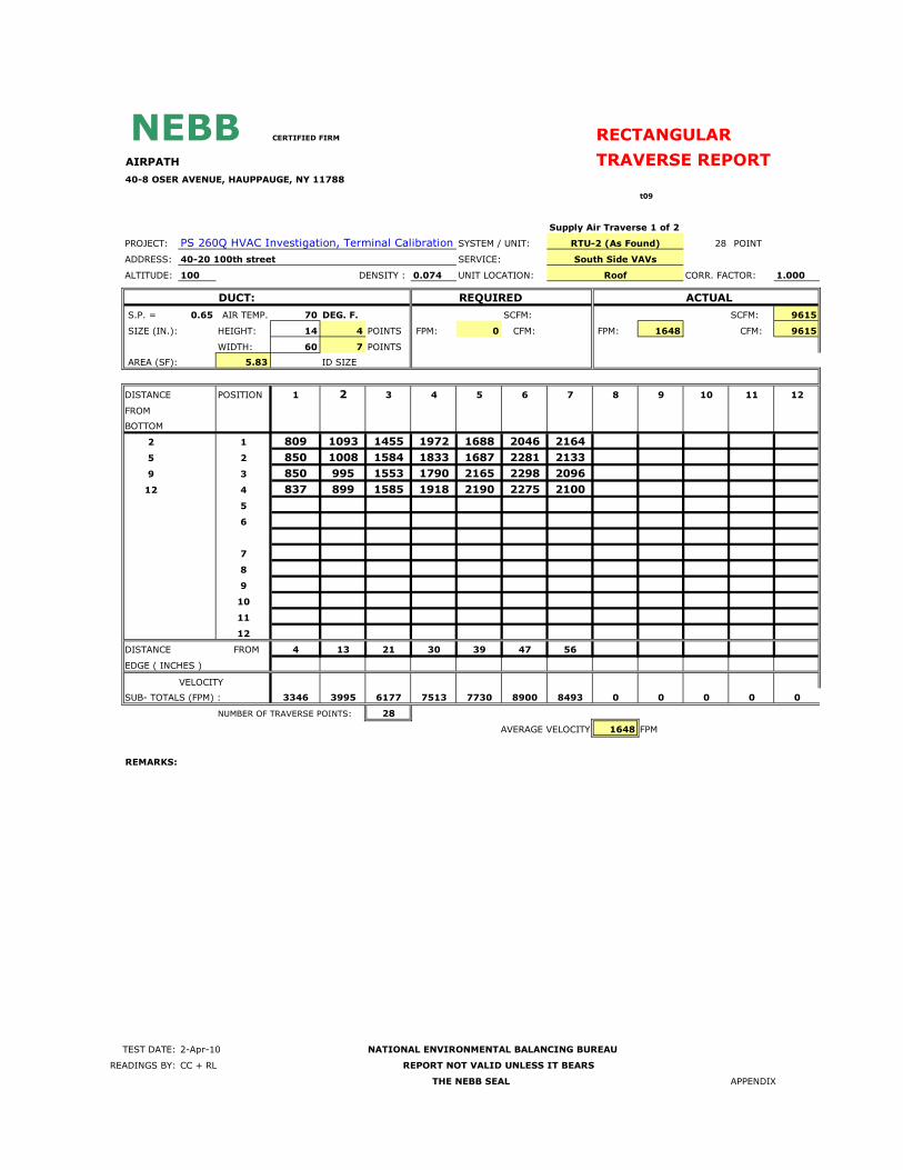
Supply Air Traverse 1 of 2
PROJECT: SYSTEM / UNIT: 28 POINT
ADDRESS: SERVICE:
ALTITUDE: 100 DENSITY : 0.074 UNIT LOCATION: CORR. FACTOR: 1.000
DUCT: REQUIRED ACTUAL
S.P. = 0.65 AIR TEMP. 70 DEG. F. SCFM: SCFM: 9615
SIZE (IN.): HEIGHT: 14 4 POINTS FPM: 0 CFM: FPM: 1648 CFM: 9615
WIDTH: 60 7 POINTS
AREA (SF): 5.83 ID SIZE
DISTANCE POSITION 1 2 3 4 5 6 7 8 9 10 11 12
FROM
BOTTOM
2 1 809 1093 1455 1972 1688 2046 2164
5 2 850 1008 1584 1833 1687 2281 2133
9 3 850 995 1553 1790 2165 2298 2096
12 4 837 899 1585 1918 2190 2275 2100
5
6
7
8
9
10
11
12
DISTANCE FROM 4 13 21 30 39 47 56
EDGE ( INCHES )
VELOCITY
SUB- TOTALS (FPM) : 3346 3995 6177 7513 7730 8900 8493 0 0 0 0 0
NUMBER OF TRAVERSE POINTS: 28
AVERAGE VELOCITY 1648 FPM
REMARKS:
TEST DATE: NATIONAL ENVIRONMENTAL BALANCING BUREAU
READINGS BY: REPORT NOT VALID UNLESS IT BEARS
THE NEBB SEAL APPENDIX
PS 260Q HVAC Investigation, Terminal Calibration and Air Device BalanceRTU-2 (As Found)
40-20 100th street South Side VAVs
Roof
2-Apr-10
CC + RL

NEBB CERTIFIED FIRM RECTANGULAR
AIRPATH TRAVERSE REPORT40-8 OSER AVENUE, HAUPPAUGE, NY 11788
t09
Supply Air Traverse 2 of 2
PROJECT: SYSTEM / UNIT: 20 POINT
ADDRESS: SERVICE:
ALTITUDE: 100 DENSITY : 0.074 UNIT LOCATION: CORR. FACTOR: 1.000
DUCT: REQUIRED ACTUAL
S.P. = 0.88 AIR TEMP. 70 DEG. F. SCFM: SCFM: 10777
SIZE (IN.): HEIGHT: 18 4 POINTS FPM: CFM: FPM: 1437 CFM: 10777
WIDTH: 60 5 POINTS
AREA (SF): 7.50 ID SIZE
DISTANCE POSITION 1 2 3 4 5 6 7 8 9 10 11 12
FROM
BOTTOM
2 1 1538 1229 1004 1651 1078
7 2 1651 1299 1379 1677 1312
11 3 1474 1390 1533 1585 1533
16 4 1449 1337 1496 1589 1534
5
6
7
8
9
10
11
12
DISTANCE FROM 6 18 30 42 54
EDGE ( INCHES )
VELOCITY
SUB- TOTALS (FPM) : 6112 5255 5412 6502 5457 0 0 0 0 0 0 0
NUMBER OF TRAVERSE POINTS: 20
AVERAGE VELOCITY 1437 FPM
REMARKS:
TEST DATE : NATIONAL ENVIRONMENTAL BALANCING BUREAU
READINGS BY: REPORT NOT VALID UNLESS IT BEARS
THE NEBB SEAL APPENDIX
RTU-2 (As Found)
South Side VAVs
Roof
PS 260Q HVAC Investigation, Terminal Calibration and Air Device Balance
40-20 100th street
CERTIFIED FIRM FAN
AIRPATH
40-8 OSER AVENUE, HAUPPAUGE, NY 11788
TAB08R
PROJECT:
ADDRESS:
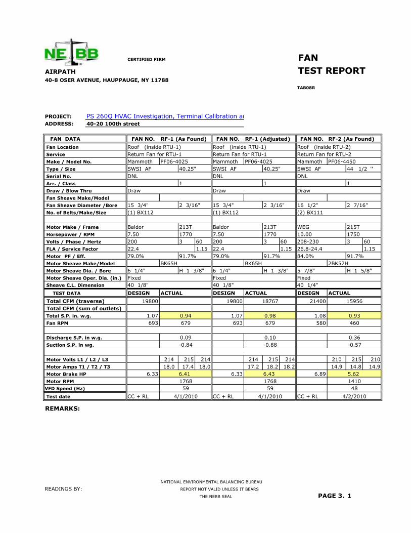
FAN DATA FAN NO. FAN NO. FAN NO.
Mammoth Mammoth Mammoth
3 60 3 60 3 60
1.15 1.15 1.15
Sheave C.L. Dimension
TEST DATA DESIGN ACTUAL DESIGN ACTUAL DESIGN ACTUAL
19800 19800 21400
1.07 1.07 1.08
693 693 580
215 214 215 214 215 210
17.4 18.0 18.2 18.2 14.8 14.9
6.33 6.33 6.89
CC + RL CC + RL CC + RL
REMARKS:
READINGS BY:
1
TEST REPORT
PS 260Q HVAC Investigation, Terminal Calibration and Air Device Balance
40-20 100th street
RF-1 (As Found) RF-1 (Adjusted) RF-2 (As Found)
Fan Location Roof (inside RTU-1) Roof (inside RTU-1) Roof (inside RTU-2)
Service Return Fan for RTU-1 Return Fan for RTU-1 Return Fan for RTU-2
Make / Model No. PF06-4025 PF06-4025 PF06-4450
Type / Size SWSI AF 40.25" SWSI AF 40.25" SWSI AF 44 1/2 ''
Serial No. DNL DNL DNL
Arr. / Class 1 1
15 3/4" 2 3/16" 16 1/2"
1
Draw / Blow Thru Draw Draw Draw
Fan Sheave Make/Model
Fan Sheave Diameter /Bore 15 3/4" 2 3/16"
213T Baldor 213T WEG
2 7/16"
No. of Belts/Make/Size (1) BX112 (1) BX112 (2) BX111
215T
Horsepower / RPM 7.50 1770 7.50 1770 10.00 1750
Motor Make / Frame Baldor
Volts / Phase / Hertz 200 200 208-230
FLA / Service Factor 22.4 22.4 26.8-24.4
Motor PF / Eff. 79.0% 91.7% 79.0% 91.7% 84.0% 91.7%
Motor Sheave Make/Model BK65H BK65H 2BK57H
Motor Sheave Dia. / Bore 6 1/4" H 1 3/8" 6 1/4" H 1 3/8" 5 7/8" H 1 5/8"
Motor Sheave Oper. Dia. (in.) Fixed Fixed Fixed
40 1/8" 40 1/8" 40 1/4"
Total CFM (traverse) 18767 15956
Total CFM (sum of outlets)
Total S.P. in. w.g. 0.94 0.98 0.93
Fan RPM 679 679 460
Discharge S.P. in w.g. 0.09 0.10 0.36
Suction S.P. in wg. -0.84 -0.88 -0.57
Motor Volts L1 / L2 / L3 214 214 210
Motor Amps T1 / T2 / T3 18.0 17.2 14.9
Motor Brake HP 6.41 6.43 5.62
Motor RPM 1768 1768 1410
VFD Speed (Hz) 59 59 48
Test date 4/1/2010 4/1/2010 4/2/2010
NATIONAL ENVIRONMENTAL BALANCING BUREAU
REPORT NOT VALID UNLESS IT BEARS
THE NEBB SEAL PAGE 3.

VAV / FP TERMINAL BOX40-8 Oser Avenue
Hauppauge, NY 11788
PROJECT:
ADDRESS: TEST INSTRUMENT: SHORTRIDGE ADM 860
VAV or FP TERMINAL REPORT SYSTEM: RTU-1 Riser 1
NUMBER/TAG: DESIGN ACTUAL
TYPE: Primary Max Airflow (CFM) 1500 1463
MAKE: Max Flow Velocity Sensor dP (in wc) 0.369 0.363
SIZE/MODEL: Primary Min Airflow (CFM) 750 743
INLET DIA (IN): Min Flow Velocity Sensor dP (in wc) 0.092 0.094
INLET AREA (S.F) Fan Speed (Hi,Med,Low,Variable) Med
K Factor Fan Airflow (CFM) 1551
Calib Factor TEST DATE:
AIR OUTLET DATA
AREA
SERVED NO AK* FLOW FLOW
MPR B102 1 375 375
MPR B102 2 375 381
MPR B102 3 375 385
MPR B102 4 375 410
1500 1551
VAV or FP TERMINAL REPORT SYSTEM: RTU-1 Riser 1
NUMBER/TAG: DESIGN ACTUAL
TYPE: Primary Max Airflow (CFM) 1550 1553
MAKE: Max Flow Velocity Sensor dP (in wc) 0.394 0.393
SIZE/MODEL: Primary Min Airflow (CFM) 775 770
INLET DIA (IN): Min Flow Velocity Sensor dP (in wc) 0.099 0.095
INLET AREA (S.F) Fan Speed (Hi,Med,Low,Variable) Med
K Factor Fan Airflow (CFM) 1518
Calib Factor TEST DATE:
AIR OUTLET DATA
AREA
SERVED NO AK* FLOW FLOW
MPR B102 1 375 337
MPR B102 2 375 379
MPR B102 3 375 375
MPR B102 4 375 378
Storage B102b 5 50 49
1550 1518
READINGS By:
PAGE 3. 1
National Environmental Balancing Bureau
Report Is Not Valid Unless Stamped With
NEBB Certification Seal
TBMS = 73.4°F
TMeasured = 72.5°F
CD 24 - 12
CD 6 x 6 TSetpoint = 72°F
CD 24 - 12
CD 24 - 12
TYPE SIZE
CD 24 - 12
2 4/9/2010
OUTLET DESIGN FINAL REMARKS
14 Airpath Measured 0.08" wc
1.068
2469
FP-VAV
Anemostat Airpath Measured 0.23" wc
QST-5014
Neuron ID: N/A
FPB - B1025 REMARKS
TMeasured = 72.5°F
TSetpoint = 72°F
TBMS = 73.7°F
CD 24 - 12
CD 24 - 12
CD 24 - 12
CD 24 - 12
OUTLET DESIGN FINAL REMARKS
TYPE SIZE
1.068
2469
-2 4/9/2010
Anemostat Airpath Measured 0.16" wc
QST-5014
14 Airpath Measured 0.05" wc
Neuron ID: N/A
FPB - B102N REMARKS
FP-VAV
A IRPATH NEBBCertified Firm TEST REPORT
PS 260Q HVAC Investigation, Terminal Calibration and Air Device Balance
40-20 100th street

VAV / FP TERMINAL BOX40-8 Oser Avenue
Hauppauge, NY 11788
PROJECT:
ADDRESS: TEST INSTRUMENT: SHORTRIDGE ADM 860
VAV or FP TERMINAL REPORT SYSTEM: RTU-1 Riser 3
NUMBER/TAG: DESIGN ACTUAL
TYPE: Primary Max Airflow (CFM) 450 457
MAKE: Max Flow Velocity Sensor dP (in wc) 0.269 0.277
SIZE/MODEL: Primary Min Airflow (CFM) 225 233
INLET DIA (IN): Min Flow Velocity Sensor dP (in wc) 0.067 0.073
INLET AREA (S.F) Fan Speed (Hi,Med,Low,Variable) Med
K Factor Fan Airflow (CFM) 456
Calib Factor TEST DATE:
AIR OUTLET DATA
AREA
SERVED NO AK* FLOW FLOW
Rm 101 1 450 456
450 456
VAV or FP TERMINAL REPORT SYSTEM: RTU-1 Riser 3
NUMBER/TAG: DESIGN ACTUAL
TYPE: Primary Max Airflow (CFM) 1150 1159
MAKE: Max Flow Velocity Sensor dP (in wc) 0.407 0.411
SIZE/MODEL: Primary Min Airflow (CFM) 575 582
INLET DIA (IN): Min Flow Velocity Sensor dP (in wc) 0.102 0.113
INLET AREA (S.F) Fan Speed (Hi,Med,Low,Variable) Med
K Factor Fan Airflow (CFM) 1143
Calib Factor TEST DATE:
AIR OUTLET DATA
AREA
SERVED NO AK* FLOW FLOW
Rm 103 1 415 420
Rm 103 2 415 435
Rm 103 3 200 180
Rm 103 4 50 57
Rm 103 5 50 51
1130 1143
READINGS By:
PAGE 3. 2
National Environmental Balancing Bureau
Report Is Not Valid Unless Stamped With
NEBB Certification Seal
TBMS = 73.5°F
TMeasured = 72.2°F
CD 8"
CD 8" TSetpoint = 72°F
LD Dual - 8"
LD 8"
TYPE SIZE
LD Dual - 8"
1802
2 4/9/2010
OUTLET DESIGN FINAL REMARKS
QST-5012
12 Airpath Measured 0.08" wc
0.785
FPB - 103 REMARKS
FP-VAV
Anemostat Airpath Measured 0.24" wc
TBMS = 75.2°F
Neuron ID: N/A
TMeasured = 74.2°F
TSetpoint = 75°F
TYPE SIZE
LD Dual - 8"
0 4/9/2010
OUTLET DESIGN FINAL REMARKS
8 Airpath Measured 0.06" wc
0.349
867
FP-VAV
Anemostat Airpath Measured 0.17" wc
QST-1708
Certified Firm TEST REPORT
Neuron ID: N/A
FPB - 101 REMARKS
PS 260Q HVAC Investigation, Terminal Calibration and Air Device Balance
40-20 100th street
A IRPATH NEBB

VAV / FP TERMINAL BOX40-8 Oser Avenue
Hauppauge, NY 11788
PROJECT:
ADDRESS: TEST INSTRUMENT: SHORTRIDGE ADM 860
VAV or FP TERMINAL REPORT SYSTEM: RTU-1 Riser 1
NUMBER/TAG: DESIGN ACTUAL
TYPE: Primary Max Airflow (CFM) 550 558
MAKE: Max Flow Velocity Sensor dP (in wc) 0.402 0.404
SIZE/MODEL:
INLET DIA (IN):
INLET AREA (S.F)
K Factor
Calib Factor TEST DATE:
AIR OUTLET DATA
AREA
SERVED NO AK* FLOW FLOW
Rm 102 - 104 1 300 285
Rm 102 - 104 2 250 225
550 510
VAV or FP TERMINAL REPORT SYSTEM: RTU-1 Riser 1
NUMBER/TAG: DESIGN ACTUAL
TYPE: Primary Max Airflow (CFM) 1200 1189
MAKE: Max Flow Velocity Sensor dP (in wc) 0.443 0.441
SIZE/MODEL: Primary Min Airflow (CFM) 600 581
INLET DIA (IN): Min Flow Velocity Sensor dP (in wc) 0.111 0.106
INLET AREA (S.F) Fan Speed (Hi,Med,Low,Variable) Med
K Factor Fan Airflow (CFM) 1182
Calib Factor TEST DATE:
AIR OUTLET DATA
AREA
SERVED NO AK* FLOW FLOW
Rm 106 1 240 240
Rm 106 2 480 480
Rm 106 3 480 462
1200 1182
READINGS By:
PAGE 3. 3
National Environmental Balancing Bureau
Report Is Not Valid Unless Stamped With
NEBB Certification Seal
TBMS = 73.9°F
TMeasured = 72.4°F
TSetpoint = 72°F
LD Dual - 8"
LD Dual - 8"
TYPE SIZE
LD 8
0 4/9/2010
OUTLET DESIGN FINAL REMARKS
12 Airpath Measured 0.11" wc
0.785
1802
FP-VAV
Anemostat Airpath Measured 0.30" wc
QST-5012
Neuron ID: N/A
FPB - 106 REMARKS
LD 12 x 12
LD 9 x 9
OUTLET DESIGN FINAL REMARKS
TYPE SIZE
0.349
867
0 4/9/2010
Anemostat Airpath Measured 0.25" wc
EZT-08
8
Neuron ID: N/A
CV - 102 REMARKS
CV
A IRPATH NEBBCertified Firm TEST REPORT
PS 260Q HVAC Investigation, Terminal Calibration and Air Device Balance
40-20 100th street
VAV / FP TERMINAL BOX40-8 Oser Avenue
Hauppauge, NY 11788
PROJECT:
ADDRESS: TEST INSTRUMENT: SHORTRIDGE ADM 860
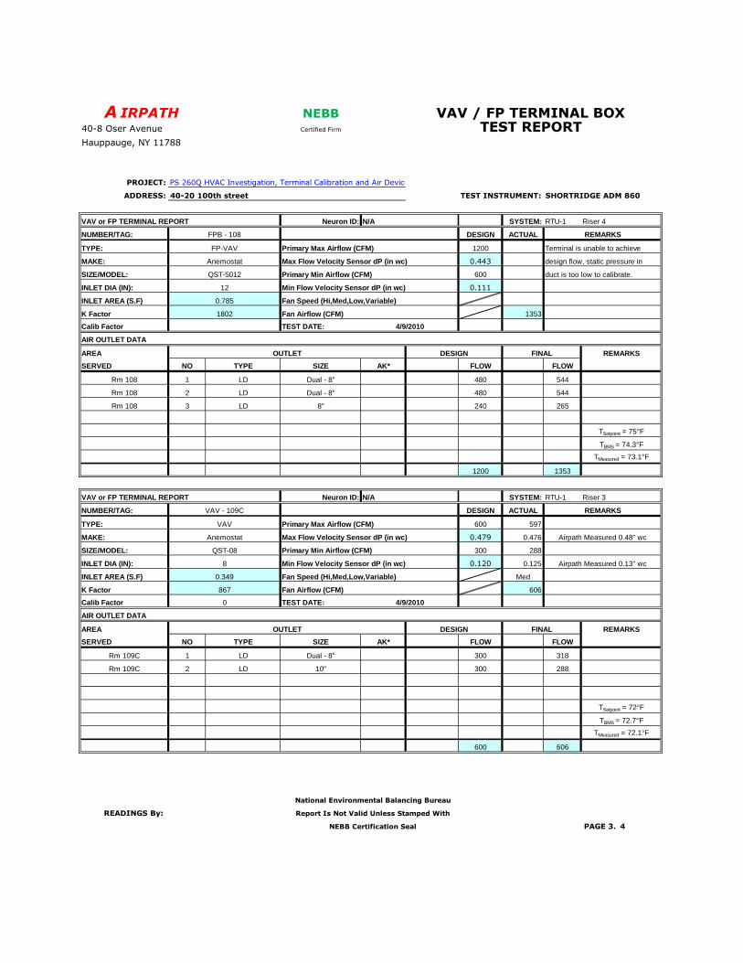
VAV or FP TERMINAL REPORT SYSTEM: RTU-1 Riser 4
NUMBER/TAG: DESIGN ACTUAL
TYPE: Primary Max Airflow (CFM) 1200
MAKE: Max Flow Velocity Sensor dP (in wc) 0.443
SIZE/MODEL: Primary Min Airflow (CFM) 600
INLET DIA (IN): Min Flow Velocity Sensor dP (in wc) 0.111
INLET AREA (S.F) Fan Speed (Hi,Med,Low,Variable)
K Factor Fan Airflow (CFM) 1353
Calib Factor TEST DATE:
AIR OUTLET DATA
AREA
SERVED NO AK* FLOW FLOW
Rm 108 1 480 544
Rm 108 2 480 544
Rm 108 3 240 265
1200 1353
VAV or FP TERMINAL REPORT SYSTEM: RTU-1 Riser 3
NUMBER/TAG: DESIGN ACTUAL
TYPE: Primary Max Airflow (CFM) 600 597
MAKE: Max Flow Velocity Sensor dP (in wc) 0.479 0.476
SIZE/MODEL: Primary Min Airflow (CFM) 300 288
INLET DIA (IN): Min Flow Velocity Sensor dP (in wc) 0.120 0.125
INLET AREA (S.F) Fan Speed (Hi,Med,Low,Variable) Med
K Factor Fan Airflow (CFM) 606
Calib Factor TEST DATE:
AIR OUTLET DATA
AREA
SERVED NO AK* FLOW FLOW
Rm 109C 1 300 318
Rm 109C 2 300 288
600 606
READINGS By:
PAGE 3. 4
National Environmental Balancing Bureau
Report Is Not Valid Unless Stamped With
NEBB Certification Seal
TBMS = 72.7°F
TMeasured = 72.1°F
TSetpoint = 72°F
LD 10"
TYPE SIZE
LD Dual - 8"
0 4/9/2010
OUTLET DESIGN FINAL REMARKS
8 Airpath Measured 0.13" wc
0.349
867
VAV
Anemostat Airpath Measured 0.48" wc
QST-08
Neuron ID: N/A
VAV - 109C REMARKS
TMeasured = 73.1°F
TSetpoint = 75°F
TBMS = 74.3°F
LD 8"
LD Dual - 8"
LD Dual - 8"
OUTLET DESIGN FINAL REMARKS
TYPE SIZE
0.785
1802
4/9/2010
Anemostat design flow, static pressure in
QST-5012 duct is too low to calibrate.
12
Neuron ID: N/A
FPB - 108 REMARKS
FP-VAV Terminal is unable to achieve
A IRPATH NEBBCertified Firm TEST REPORT
PS 260Q HVAC Investigation, Terminal Calibration and Air Device Balance
40-20 100th street
VAV / FP TERMINAL BOX40-8 Oser Avenue
Hauppauge, NY 11788
PROJECT:
ADDRESS: TEST INSTRUMENT: SHORTRIDGE ADM 860
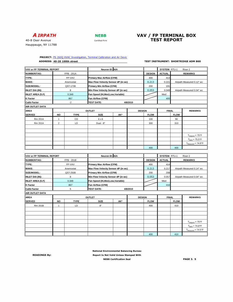
VAV or FP TERMINAL REPORT SYSTEM: RTU-1 Riser 2
NUMBER/TAG: DESIGN ACTUAL
TYPE: Primary Max Airflow (CFM) 400 413
MAKE: Max Flow Velocity Sensor dP (in wc) 0.213 0.221
SIZE/MODEL: Primary Min Airflow (CFM) 200 191
INLET DIA (IN): Min Flow Velocity Sensor dP (in wc) 0.053 0.049
INLET AREA (S.F) Fan Speed (Hi,Med,Low,Variable) Med
K Factor Fan Airflow (CFM) 400
Calib Factor TEST DATE:
AIR OUTLET DATA
AREA
SERVED NO AK* FLOW FLOW
Rm 201A 1 100 90
Rm 201A 2 300 310
400 400
VAV or FP TERMINAL REPORT SYSTEM: RTU-1 Riser 2
NUMBER/TAG: DESIGN ACTUAL
TYPE: Primary Max Airflow (CFM) 400 414
MAKE: Max Flow Velocity Sensor dP (in wc) 0.213 0.217
SIZE/MODEL: Primary Min Airflow (CFM) 200 208
INLET DIA (IN): Min Flow Velocity Sensor dP (in wc) 0.053 0.057
INLET AREA (S.F) Fan Speed (Hi,Med,Low,Variable) Med
K Factor Fan Airflow (CFM) 410
Calib Factor TEST DATE:
AIR OUTLET DATA
AREA
SERVED NO AK* FLOW FLOW
Rm 201B 1 400 410
400 410
READINGS By:
PAGE 3. 5
National Environmental Balancing Bureau
Report Is Not Valid Unless Stamped With
NEBB Certification Seal
TBMS = 74.8°F
TMeasured = 74.5°F
TSetpoint = 75°F
TYPE SIZE
LD 8"
5 4/8/2010
OUTLET DESIGN FINAL REMARKS
8 Airpath Measured 0.04" wc
0.349
867
FP-VAV
Anemostat Airpath Measured 0.14" wc
QST-2508
Neuron ID: N/A
FPB - 201B REMARKS
TMeasured = 74.9°F
TSetpoint = 75°F
TBMS = 75.5°F
CD 6 x 6
LD Dual - 8"
OUTLET DESIGN FINAL REMARKS
TYPE SIZE
0.349
867
-2 4/8/2010
Anemostat Airpath Measured 0.12" wc
QST-1708
8 Airpath Measured 0.04" wc
Neuron ID: N/A
FPB - 201A REMARKS
FP-VAV
A IRPATH NEBBCertified Firm TEST REPORT
PS 260Q HVAC Investigation, Terminal Calibration and Air Device Balance
40-20 100th street

VAV / FP TERMINAL BOX40-8 Oser Avenue
Hauppauge, NY 11788
PROJECT:
ADDRESS: TEST INSTRUMENT: SHORTRIDGE ADM 860
VAV or FP TERMINAL REPORT SYSTEM: RTU-1 Riser 2
NUMBER/TAG: DESIGN ACTUAL
TYPE: Primary Max Airflow (CFM) 600 590
MAKE: Max Flow Velocity Sensor dP (in wc) 0.197 0.187
SIZE/MODEL: Primary Min Airflow (CFM) 300 296
INLET DIA (IN): Min Flow Velocity Sensor dP (in wc) 0.049 0.054
INLET AREA (S.F) Fan Speed (Hi,Med,Low,Variable) Med
K Factor Fan Airflow (CFM) 560
Calib Factor TEST DATE:
AIR OUTLET DATA
AREA
SERVED NO AK* FLOW FLOW
Rm 205 1 200 180
Rm 205 2 400 380
600 560
VAV or FP TERMINAL REPORT SYSTEM: RTU-1 Riser 1
NUMBER/TAG: DESIGN ACTUAL
TYPE: Primary Max Airflow (CFM) 900 875
MAKE: Max Flow Velocity Sensor dP (in wc) 0.442 0.424
SIZE/MODEL: Primary Min Airflow (CFM) 450 420
INLET DIA (IN): Min Flow Velocity Sensor dP (in wc) 0.111 0.098
INLET AREA (S.F) Fan Speed (Hi,Med,Low,Variable)
K Factor Fan Airflow (CFM) 1200
Calib Factor TEST DATE:
AIR OUTLET DATA
AREA
SERVED NO AK* FLOW FLOW
Rm 206 1 300 400
Rm 206 2 600 800
900 1200
READINGS By:
PAGE 3. 6
National Environmental Balancing Bureau
Report Is Not Valid Unless Stamped With
NEBB Certification Seal
TBMS = 75.9°F
TMeasured = 74.1°F
TSetpoint = 75°F
LD Dual - 10" knobs are broken.
Unable to adjust.
TYPE SIZE
LD 10 Fan speed control
0 4/8/2010
OUTLET DESIGN FINAL REMARKS
10 Airpath Measured 0.08" wc
0.545 Fan speed knobs are broken
1353
FP-VAV
Anemostat Airpath Measured 0.24" wc
QST-2510
Neuron ID: N/A
FPB - 206 REMARKS
TMeasured = 73.1°F
TSetpoint = 75°F
TBMS = 75.2°F
LD 8"
LD Dual - 8"
OUTLET DESIGN FINAL REMARKS
TYPE SIZE
0.545
1353
-2 4/8/2010
Anemostat Airpath Measured 0.11" wc
QST-2510
10 Airpath Measured 0.05" wc
Neuron ID: N/A
FPB - 205 REMARKS
FP-VAV
A IRPATH NEBBCertified Firm TEST REPORT
PS 260Q HVAC Investigation, Terminal Calibration and Air Device Balance
40-20 100th street

VAV / FP TERMINAL BOX40-8 Oser Avenue
Hauppauge, NY 11788
PROJECT:
ADDRESS: TEST INSTRUMENT: SHORTRIDGE ADM 860
VAV or FP TERMINAL REPORT SYSTEM: RTU-1 Riser 2
NUMBER/TAG: DESIGN ACTUAL
TYPE: Primary Max Airflow (CFM) 1200 1020
MAKE: Max Flow Velocity Sensor dP (in wc) 0.443 0.341
SIZE/MODEL: Primary Min Airflow (CFM) 600 585
INLET DIA (IN): Min Flow Velocity Sensor dP (in wc) 0.111 0.104
INLET AREA (S.F) Fan Speed (Hi,Med,Low,Variable) Med
K Factor Fan Airflow (CFM) 1178
Calib Factor TEST DATE:
AIR OUTLET DATA
AREA
SERVED NO AK* FLOW FLOW
Rm 207 1 400 405
Rm 207 2 200 195
Rm 207 3 300 292
Rm 207 4 300 286
1200 1178
VAV or FP TERMINAL REPORT SYSTEM: RTU-1 Riser 1
NUMBER/TAG: DESIGN ACTUAL
TYPE: Primary Max Airflow (CFM) 750 754
MAKE: Max Flow Velocity Sensor dP (in wc) 0.307 0.306
SIZE/MODEL: Primary Min Airflow (CFM) 375 372
INLET DIA (IN): Min Flow Velocity Sensor dP (in wc) 0.077 0.077
INLET AREA (S.F) Fan Speed (Hi,Med,Low,Variable) Med
K Factor Fan Airflow (CFM) 750
Calib Factor TEST DATE:
AIR OUTLET DATA
AREA
SERVED NO AK* FLOW FLOW
Rm 208 1 500 510
Rm 208 2 250 240
750 750
READINGS By:
PAGE 3. 7
National Environmental Balancing Bureau
Report Is Not Valid Unless Stamped With
NEBB Certification Seal
TBMS = 76.1°F
TMeasured = 75.1°F
TSetpoint = 75°F
LD 8"
TYPE SIZE
LD Dual - 8"
2 4/8/2010
OUTLET DESIGN FINAL REMARKS
10 Airpath Measured 0.06" wc
0.545
1353
FP-VAV
Anemostat Airpath Measured 0.20" wc
QST-2510
Neuron ID: N/A
FPB - 208 REMARKS
TMeasured = 75.8°F
TSetpoint = 75°F
TBMS = 76.1°F
LD 10"
LD 10"
LD Dual - 8"
LD 8"
OUTLET DESIGN FINAL REMARKS
TYPE SIZE
0.785
1802
-2 4/8/2010
Anemostat maximum flow setting.
QST-5012
12
Neuron ID: N/A
FPB - 207 REMARKS
FP-VAV Terminal is unable to achieve
A IRPATH NEBBCertified Firm TEST REPORT
PS 260Q HVAC Investigation, Terminal Calibration and Air Device Balance
40-20 100th street
VAV / FP TERMINAL BOX40-8 Oser Avenue
Hauppauge, NY 11788
PROJECT:
ADDRESS: TEST INSTRUMENT: SHORTRIDGE ADM 860
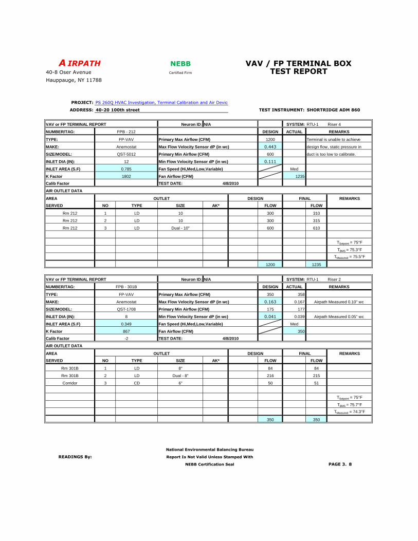
VAV or FP TERMINAL REPORT SYSTEM: RTU-1 Riser 4
NUMBER/TAG: DESIGN ACTUAL
TYPE: Primary Max Airflow (CFM) 1200
MAKE: Max Flow Velocity Sensor dP (in wc) 0.443
SIZE/MODEL: Primary Min Airflow (CFM) 600
INLET DIA (IN): Min Flow Velocity Sensor dP (in wc) 0.111
INLET AREA (S.F) Fan Speed (Hi,Med,Low,Variable) Med
K Factor Fan Airflow (CFM) 1235
Calib Factor TEST DATE:
AIR OUTLET DATA
AREA
SERVED NO AK* FLOW FLOW
Rm 212 1 300 310
Rm 212 2 300 315
Rm 212 3 600 610
1200 1235
VAV or FP TERMINAL REPORT SYSTEM: RTU-1 Riser 2
NUMBER/TAG: DESIGN ACTUAL
TYPE: Primary Max Airflow (CFM) 350 358
MAKE: Max Flow Velocity Sensor dP (in wc) 0.163 0.167
SIZE/MODEL: Primary Min Airflow (CFM) 175 177
INLET DIA (IN): Min Flow Velocity Sensor dP (in wc) 0.041 0.039
INLET AREA (S.F) Fan Speed (Hi,Med,Low,Variable) Med
K Factor Fan Airflow (CFM) 350
Calib Factor TEST DATE:
AIR OUTLET DATA
AREA
SERVED NO AK* FLOW FLOW
Rm 301B 1 84 84
Rm 301B 2 216 215
Corridor 3 50 51
350 350
READINGS By:
PAGE 3. 8
National Environmental Balancing Bureau
Report Is Not Valid Unless Stamped With
NEBB Certification Seal
TBMS = 75.7°F
TMeasured = 74.3°F
TSetpoint = 75°F
LD Dual - 8"
CD 6"
TYPE SIZE
LD 8"
-2 4/8/2010
OUTLET DESIGN FINAL REMARKS
8 Airpath Measured 0.05" wc
0.349
867
FP-VAV
Anemostat Airpath Measured 0.10" wc
QST-1708
Neuron ID: N/A
FPB - 301B REMARKS
TMeasured = 75.5°F
TSetpoint = 75°F
TBMS = 75.3°F
LD Dual - 10"
LD 10
LD 10
OUTLET DESIGN FINAL REMARKS
TYPE SIZE
0.785
1802
4/8/2010
Anemostat design flow, static pressure in
QST-5012 duct is too low to calibrate.
12
Neuron ID: N/A
FPB - 212 REMARKS
FP-VAV Terminal is unable to achieve
A IRPATH NEBBCertified Firm TEST REPORT
PS 260Q HVAC Investigation, Terminal Calibration and Air Device Balance
40-20 100th street

VAV / FP TERMINAL BOX40-8 Oser Avenue
Hauppauge, NY 11788
PROJECT:
ADDRESS: TEST INSTRUMENT: SHORTRIDGE ADM 860
VAV or FP TERMINAL REPORT SYSTEM: RTU-1 Riser 2
NUMBER/TAG: DESIGN ACTUAL
TYPE: Primary Max Airflow (CFM) 950 964
MAKE: Max Flow Velocity Sensor dP (in wc) 0.278 0.276
SIZE/MODEL: Primary Min Airflow (CFM) 475 469
INLET DIA (IN): Min Flow Velocity Sensor dP (in wc) 0.069 0.068
INLET AREA (S.F) Fan Speed (Hi,Med,Low,Variable) Med
K Factor Fan Airflow (CFM) 914
Calib Factor TEST DATE:
AIR OUTLET DATA
AREA
SERVED NO AK* FLOW FLOW
Rm 303 1 475 457
Rm 303 2 475 457
950 914
VAV or FP TERMINAL REPORT SYSTEM: RTU-1 Riser 2
NUMBER/TAG: DESIGN ACTUAL
TYPE: Primary Max Airflow (CFM) 950 964
MAKE: Max Flow Velocity Sensor dP (in wc) 0.278 0.28
SIZE/MODEL: Primary Min Airflow (CFM) 475 442
INLET DIA (IN): Min Flow Velocity Sensor dP (in wc) 0.069 0.059
INLET AREA (S.F) Fan Speed (Hi,Med,Low,Variable)
K Factor Fan Airflow (CFM) 0
Calib Factor TEST DATE:
AIR OUTLET DATA
AREA
SERVED NO AK* FLOW FLOW
Rm 305 1 500
Rm 305 2 450
950 0
READINGS By:
PAGE 3. 9
National Environmental Balancing Bureau
Report Is Not Valid Unless Stamped With
NEBB Certification Seal
Fan not running.
LD Dual - 8" controller, speed
adjustment not working
TYPE SIZE
LD Dual - 8" Broken fan motor
0 4/8/2010
OUTLET DESIGN FINAL REMARKS
12 Airpath Measured 0.06" wc
0.785 Fan not running
1802
FP-VAV
Anemostat Airpath Measured 0.19" wc
QST-5012
Neuron ID: N/A
FPB - 305 REMARKS
TMeasured = 73.5°F
TSetpoint = 75°F
TBMS = 75.5°F
LD Dual - 8"
LD Dual - 8"
OUTLET DESIGN FINAL REMARKS
TYPE SIZE
0.785
1802
2 4/8/2010
Anemostat Airpath Measured 0.17" wc
QST-5012
12 Airpath Measured 0.07" wc
Neuron ID: N/A
FPB - 303 REMARKS
FP-VAV
A IRPATH NEBBCertified Firm TEST REPORT
PS 260Q HVAC Investigation, Terminal Calibration and Air Device Balance
40-20 100th street

VAV / FP TERMINAL BOX40-8 Oser Avenue
Hauppauge, NY 11788
PROJECT:
ADDRESS: TEST INSTRUMENT: SHORTRIDGE ADM 860
VAV or FP TERMINAL REPORT SYSTEM: RTU-1 Riser 1
NUMBER/TAG: DESIGN ACTUAL
TYPE: Primary Max Airflow (CFM) 400 392
MAKE: Max Flow Velocity Sensor dP (in wc) 0.213 0.202
SIZE/MODEL: Primary Min Airflow (CFM) 200 214
INLET DIA (IN): Min Flow Velocity Sensor dP (in wc) 0.053 0.064
INLET AREA (S.F)
K Factor
Calib Factor TEST DATE:
AIR OUTLET DATA
AREA
SERVED NO AK* FLOW FLOW
Rm 306 1 400 412
400 412
VAV or FP TERMINAL REPORT SYSTEM: RTU-1 Riser 1
NUMBER/TAG: DESIGN ACTUAL
TYPE: Primary Max Airflow (CFM) 1050 0
MAKE: Max Flow Velocity Sensor dP (in wc) 0.340 0
SIZE/MODEL: Primary Min Airflow (CFM) 525 0
INLET DIA (IN): Min Flow Velocity Sensor dP (in wc) 0.085 0
INLET AREA (S.F) Fan Speed (Hi,Med,Low,Variable) Med
K Factor Fan Airflow (CFM) 975
Calib Factor TEST DATE:
AIR OUTLET DATA
AREA
SERVED NO AK* FLOW FLOW
Rm 308 1 525 484
Rm 308 2 525 491
1050 975
READINGS By:
PAGE 3. 10
National Environmental Balancing Bureau
Report Is Not Valid Unless Stamped With
NEBB Certification Seal
LD Dual - 8"
TYPE SIZE
LD Dual - 8"
4/8/2010
OUTLET DESIGN FINAL REMARKS
12 Unable to calibrate.
0.785
1802
FP-VAV Terminal not communicating.
Anemostat Unable to adjust CFM setpoint
QST-5012 in BMS, stays at 0 CFM.
Neuron ID: N/A
FPB - 308 REMARKS
TMeasured = 74.6°F
TSetpoint = 75°F
TBMS = 75.3°F
LD 10"
OUTLET DESIGN FINAL REMARKS
TYPE SIZE
0.349
867
-4 4/8/2010
Anemostat Airpath Measured 0.25" wc
EZTS-08
8 Airpath Measured 0.08" wc
Neuron ID: N/A
VAV - 306 REMARKS
VAV
A IRPATH NEBBCertified Firm TEST REPORT
PS 260Q HVAC Investigation, Terminal Calibration and Air Device Balance
40-20 100th street
VAV / FP TERMINAL BOX40-8 Oser Avenue
Hauppauge, NY 11788
PROJECT:
ADDRESS: TEST INSTRUMENT: SHORTRIDGE ADM 860
VAV or FP TERMINAL REPORT SYSTEM: RTU-1 Riser 1
NUMBER/TAG: DESIGN ACTUAL
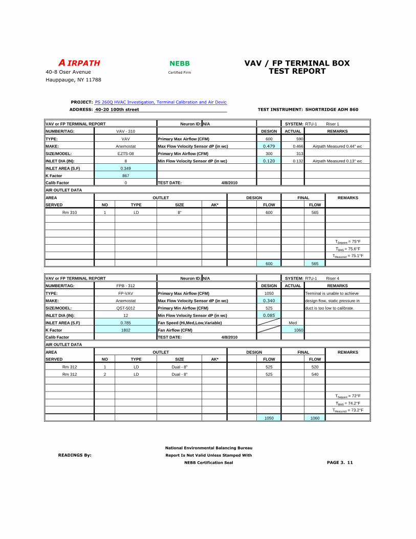
TYPE: Primary Max Airflow (CFM) 600 590
MAKE: Max Flow Velocity Sensor dP (in wc) 0.479 0.466
SIZE/MODEL: Primary Min Airflow (CFM) 300 313
INLET DIA (IN): Min Flow Velocity Sensor dP (in wc) 0.120 0.132
INLET AREA (S.F)
K Factor
Calib Factor TEST DATE:
AIR OUTLET DATA
AREA
SERVED NO AK* FLOW FLOW
Rm 310 1 600 565
600 565
VAV or FP TERMINAL REPORT SYSTEM: RTU-1 Riser 4
NUMBER/TAG: DESIGN ACTUAL
TYPE: Primary Max Airflow (CFM) 1050
MAKE: Max Flow Velocity Sensor dP (in wc) 0.340
SIZE/MODEL: Primary Min Airflow (CFM) 525
INLET DIA (IN): Min Flow Velocity Sensor dP (in wc) 0.085
INLET AREA (S.F) Fan Speed (Hi,Med,Low,Variable) Med
K Factor Fan Airflow (CFM) 1060
Calib Factor TEST DATE:
AIR OUTLET DATA
AREA
SERVED NO AK* FLOW FLOW
Rm 312 1 525 520
Rm 312 2 525 540
1050 1060
READINGS By:
PAGE 3. 11
National Environmental Balancing Bureau
Report Is Not Valid Unless Stamped With
NEBB Certification Seal
TBMS = 74.2°F
TMeasured = 73.2°F
TSetpoint = 72°F
LD Dual - 8"
TYPE SIZE
LD Dual - 8"
4/8/2010
OUTLET DESIGN FINAL REMARKS
12
0.785
1802
FP-VAV Terminal is unable to achieve
Anemostat design flow, static pressure in
QST-5012 duct is too low to calibrate.
Neuron ID: N/A
FPB - 312 REMARKS
TMeasured = 75.1°F
TSetpoint = 75°F
TBMS = 75.6°F
LD 8"
OUTLET DESIGN FINAL REMARKS
TYPE SIZE
0.349
867
0 4/8/2010
Anemostat Airpath Measured 0.44" wc
EZTS-08
8 Airpath Measured 0.13" wc
Neuron ID: N/A
VAV - 310 REMARKS
VAV
A IRPATH NEBBCertified Firm TEST REPORT
PS 260Q HVAC Investigation, Terminal Calibration and Air Device Balance
40-20 100th street

VAV / FP TERMINAL BOX40-8 Oser Avenue
Hauppauge, NY 11788
PROJECT:
ADDRESS: TEST INSTRUMENT: SHORTRIDGE ADM 860
VAV or FP TERMINAL REPORT SYSTEM: RTU-1 Riser 2
NUMBER/TAG: DESIGN ACTUAL
TYPE: Primary Max Airflow (CFM) 350 343
MAKE: Max Flow Velocity Sensor dP (in wc) 0.163 0.164
SIZE/MODEL: Primary Min Airflow (CFM) 175 163
INLET DIA (IN): Min Flow Velocity Sensor dP (in wc) 0.041 0.041
INLET AREA (S.F) Fan Speed (Hi,Med,Low,Variable) Med
K Factor Fan Airflow (CFM) 356
Calib Factor TEST DATE:
AIR OUTLET DATA
AREA
SERVED NO AK* FLOW FLOW
Rm 401B 1 84 85
Rm 401B 2 216 220
Corridor 3 50 51
350 356
VAV or FP TERMINAL REPORT SYSTEM: RTU-1 Riser 2
NUMBER/TAG: DESIGN ACTUAL
TYPE: Primary Max Airflow (CFM) 950 937
MAKE: Max Flow Velocity Sensor dP (in wc) 0.278 0.267
SIZE/MODEL: Primary Min Airflow (CFM) 475 468
INLET DIA (IN): Min Flow Velocity Sensor dP (in wc) 0.069 0.065
INLET AREA (S.F) Fan Speed (Hi,Med,Low,Variable) Med
K Factor Fan Airflow (CFM) 896
Calib Factor TEST DATE:
AIR OUTLET DATA
AREA
SERVED NO AK* FLOW FLOW
Rm 403 1 475 450
Rm 403 2 475 446
950 896
READINGS By:
PAGE 3. 12
National Environmental Balancing Bureau
CC + RL Report Is Not Valid Unless Stamped With
NEBB Certification Seal
TBMS = 70.0°F
TMeasured = 71.0°F
TSetpoint = 72°F
LD Dual - 8"
TYPE SIZE
LD Dual - 8"
0 4/5/2010
OUTLET DESIGN FINAL REMARKS
12 Airpath Measured 0.02"
0.785
1802
FP-VAV
Anemostat Airpath Measured 0.15"
QST-5012
Neuron ID: N/A
FPB - 403 REMARKS
TMeasured = 71.5°F
TSetpoint = 72°F
TBMS = 71.9°F
CD 6x6
LD 8"
LD Dual - 8"
OUTLET DESIGN FINAL REMARKS
TYPE SIZE
0.349
867
0 4/5/2010
Anemostat Airpath Measured 0.11"
QST-1708
8 Airpath Measured 0.03"
Neuron ID: N/A
FPB - 401B REMARKS
FP-VAV
A IRPATH NEBBCertified Firm TEST REPORT
PS 260Q HVAC Investigation, Terminal Calibration and Air Device Balance
40-20 100th street

VAV / FP TERMINAL BOX40-8 Oser Avenue
Hauppauge, NY 11788
PROJECT:
ADDRESS: TEST INSTRUMENT: SHORTRIDGE ADM 860
VAV or FP TERMINAL REPORT SYSTEM: RTU-1 Riser 2
NUMBER/TAG: DESIGN ACTUAL
TYPE: Primary Max Airflow (CFM) 950 943
MAKE: Max Flow Velocity Sensor dP (in wc) 0.278 0.271
SIZE/MODEL: Primary Min Airflow (CFM) 475 467
INLET DIA (IN): Min Flow Velocity Sensor dP (in wc) 0.069 0.065
INLET AREA (S.F) Fan Speed (Hi,Med,Low,Variable) Med
K Factor Fan Airflow (CFM) 949
Calib Factor TEST DATE:
AIR OUTLET DATA
AREA
SERVED NO AK* FLOW FLOW
Rm 405 1 500 510
Rm 405 2 450 439
950 949
VAV or FP TERMINAL REPORT SYSTEM: RTU-1 Riser 1
NUMBER/TAG: DESIGN ACTUAL
TYPE: Primary Max Airflow (CFM) 240 236
MAKE: Max Flow Velocity Sensor dP (in wc) 0.077 0.081
SIZE/MODEL: Primary Min Airflow (CFM) 120 117
INLET DIA (IN): Min Flow Velocity Sensor dP (in wc) 0.019 0.019
INLET AREA (S.F)
K Factor
Calib Factor TEST DATE:
AIR OUTLET DATA
AREA
SERVED NO AK* FLOW FLOW
Rm 406 1 240 224
240 224
READINGS By:
PAGE 3. 13
A IRPATH NEBBCertified Firm TEST REPORT
PS 260Q HVAC Investigation, Terminal Calibration and Air Device Balance
40-20 100th street
Neuron ID: N/A
FPB - 405 REMARKS
FP-VAV
Anemostat Airpath Measured 0.23"
QST-5012
12 Airpath Measured 0.12"
0.785
1802
2 4/5/2010
OUTLET DESIGN FINAL REMARKS
TYPE SIZE
LD Dual - 8"
LD Dual - 8"
TSetpoint = 72°F
TBMS = 72.3°F
Neuron ID: N/A
VAV - 406 REMARKS
TMeasured = 71.5°F
FP-VAV
Anemostat Airpath Measured 0.032"
EZTS-08
8 Airpath Measured 0.005"
0.349
867
-5 4/5/2010
OUTLET DESIGN FINAL REMARKS
TYPE SIZE
LD 10"
TSetpoint = 72°F
TBMS = 71.6°F
TMeasured = 70.5°F
National Environmental Balancing Bureau
CC + RL Report Is Not Valid Unless Stamped With
NEBB Certification Seal
VAV / FP TERMINAL BOX40-8 Oser Avenue
Hauppauge, NY 11788
PROJECT:
ADDRESS: TEST INSTRUMENT: SHORTRIDGE ADM 860
VAV or FP TERMINAL REPORT SYSTEM: RTU-1 Riser 1
NUMBER/TAG: DESIGN ACTUAL
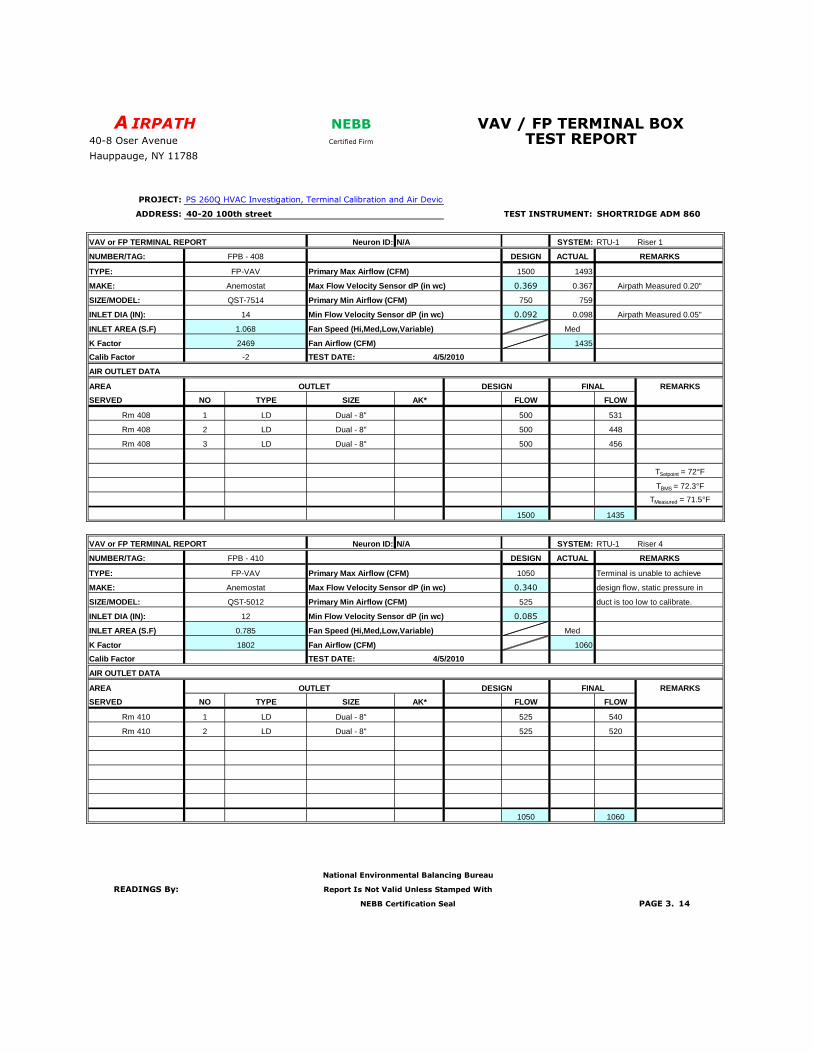
TYPE: Primary Max Airflow (CFM) 1500 1493
MAKE: Max Flow Velocity Sensor dP (in wc) 0.369 0.367
SIZE/MODEL: Primary Min Airflow (CFM) 750 759
INLET DIA (IN): Min Flow Velocity Sensor dP (in wc) 0.092 0.098
INLET AREA (S.F) Fan Speed (Hi,Med,Low,Variable) Med
K Factor Fan Airflow (CFM) 1435
Calib Factor TEST DATE:
AIR OUTLET DATA
AREA
SERVED NO AK* FLOW FLOW
Rm 408 1 500 531
Rm 408 2 500 448
Rm 408 3 500 456
1500 1435
VAV or FP TERMINAL REPORT SYSTEM: RTU-1 Riser 4
NUMBER/TAG: DESIGN ACTUAL
TYPE: Primary Max Airflow (CFM) 1050
MAKE: Max Flow Velocity Sensor dP (in wc) 0.340
SIZE/MODEL: Primary Min Airflow (CFM) 525
INLET DIA (IN): Min Flow Velocity Sensor dP (in wc) 0.085
INLET AREA (S.F) Fan Speed (Hi,Med,Low,Variable) Med
K Factor Fan Airflow (CFM) 1060
Calib Factor TEST DATE:
AIR OUTLET DATA
AREA
SERVED NO AK* FLOW FLOW
Rm 410 1 525 540
Rm 410 2 525 520
1050 1060
READINGS By:
PAGE 3. 14
A IRPATH NEBBCertified Firm TEST REPORT
PS 260Q HVAC Investigation, Terminal Calibration and Air Device Balance
40-20 100th street
Neuron ID: N/A
FPB - 408 REMARKS
FP-VAV
Anemostat Airpath Measured 0.20"
QST-7514
14 Airpath Measured 0.05"
1.068
2469
-2 4/5/2010
OUTLET DESIGN FINAL REMARKS
TYPE SIZE
LD Dual - 8"
LD Dual - 8"
LD Dual - 8"
TSetpoint = 72°F
TBMS = 72.3°F
Neuron ID: N/A
FPB - 410 REMARKS
TMeasured = 71.5°F
FP-VAV Terminal is unable to achieve
Anemostat design flow, static pressure in
QST-5012 duct is too low to calibrate.
12
0.785
1802
4/5/2010
OUTLET DESIGN FINAL REMARKS
TYPE SIZE
LD Dual - 8"
LD Dual - 8"
National Environmental Balancing Bureau
Report Is Not Valid Unless Stamped With
NEBB Certification Seal
VAV / FP TERMINAL BOX40-8 Oser Avenue
Hauppauge, NY 11788
PROJECT:
ADDRESS: TEST INSTRUMENT: SHORTRIDGE ADM 860
VAV or FP TERMINAL REPORT SYSTEM: RTU-1 Riser 2
NUMBER/TAG: DESIGN ACTUAL
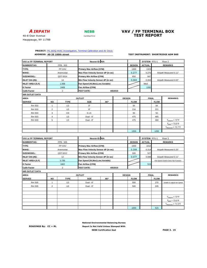
TYPE: Primary Max Airflow (CFM) 1300 1323
MAKE: Max Flow Velocity Sensor dP (in wc) 0.277 0.276
SIZE/MODEL: Primary Min Airflow (CFM) 650 647
INLET DIA (IN): Min Flow Velocity Sensor dP (in wc) 0.069 0.063
INLET AREA (S.F) Fan Speed (Hi,Med,Low,Variable) Med
K Factor Fan Airflow (CFM) 1282
Calib Factor TEST DATE:
AIR OUTLET DATA
AREA
SERVED NO AK* FLOW FLOW
Rm 503 1 84 84
Rm 503 2 216 221
Rm 503 3 50 52
Rm 503 4 475 465
Rm 503 5 475 460
1300 1282
VAV or FP TERMINAL REPORT SYSTEM: RTU-1 Riser 3
NUMBER/TAG: DESIGN ACTUAL
TYPE: Primary Max Airflow (CFM) 1000 1012
MAKE: Max Flow Velocity Sensor dP (in wc) 0.308 0.314
SIZE/MODEL: Primary Min Airflow (CFM) 500 527
INLET DIA (IN): Min Flow Velocity Sensor dP (in wc) 0.077 0.088
INLET AREA (S.F) Fan Speed (Hi,Med,Low,Variable)
K Factor Fan Airflow (CFM) 515
Calib Factor TEST DATE:
AIR OUTLET DATA
AREA
SERVED NO AK* FLOW FLOW
Rm 505 1 500 270
Rm 505 2 500 245
1000 515
READINGS By:
PAGE 3. 15
A IRPATH NEBBCertified Firm TEST REPORT
PS 260Q HVAC Investigation, Terminal Calibration and Air Device Balance
40-20 100th street
Neuron ID: N/A
FPB - 503 REMARKS
FP-VAV
Anemostat Airpath Measured 0.11"
QST-5014
14 Airpath Measured 0.02"
1.068
2469
2 4/5/2010
OUTLET DESIGN FINAL REMARKS
TYPE SIZE
LD 8"
LD 8"
CD 6 x 6
LD Dual - 8"
LD Dual - 8" TSetpoint = 72°F
TBMS = 73.5°F
Neuron ID: N/A
FPB - 505 REMARKS
TMeasured = 72.7°F
FP-VAV
Anemostat Airpath Measured 0.20"
QST-5012
12 Airpath Measured 0.11"
0.785 Fan Speed Switch Does Not Function
1802
2 4/5/2010
OUTLET DESIGN FINAL REMARKS
TYPE SIZE
LD Dual - 8" Unable to adjust fan speed
LD Dual - 8"
TSetpoint = 72°F
TBMS = 73.0°F
TMeasured = 71.5°F
National Environmental Balancing Bureau
CC + RL Report Is Not Valid Unless Stamped With
NEBB Certification Seal

VAV / FP TERMINAL BOX40-8 Oser Avenue
Hauppauge, NY 11788
PROJECT:
ADDRESS: TEST INSTRUMENT: SHORTRIDGE ADM 860
VAV or FP TERMINAL REPORT SYSTEM: RTU-1 Riser 4
NUMBER/TAG: DESIGN ACTUAL
TYPE: Primary Max Airflow (CFM) 400
MAKE: Max Flow Velocity Sensor dP (in wc) 0.727
SIZE/MODEL: Primary Min Airflow (CFM) 200
INLET DIA (IN): Min Flow Velocity Sensor dP (in wc) 0.182
INLET AREA (S.F)
K Factor
Calib Factor TEST DATE:
AIR OUTLET DATA
AREA
SERVED NO AK* FLOW FLOW
Rm 506 1 400 210
400 210
VAV or FP TERMINAL REPORT SYSTEM: RTU-1 Riser 4
NUMBER/TAG: DESIGN ACTUAL
TYPE: Primary Max Airflow (CFM) 1500
MAKE: Max Flow Velocity Sensor dP (in wc) 0.369
SIZE/MODEL: Primary Min Airflow (CFM) 750
INLET DIA (IN): Min Flow Velocity Sensor dP (in wc) 0.092
INLET AREA (S.F) Fan Speed (Hi,Med,Low,Variable) Med
K Factor Fan Airflow (CFM) 1495
Calib Factor TEST DATE:
AIR OUTLET DATA
AREA
SERVED NO AK* FLOW FLOW
Rm 508 1 500 490
Rm 508 2 500 495
Rm 508 3 500 510
1500 1495
READINGS By:
PAGE 3. 16
A IRPATH NEBBCertified Firm TEST REPORT
PS 260Q HVAC Investigation, Terminal Calibration and Air Device Balance
40-20 100th street
Neuron ID: N/A
VAV - 506 REMARKS
VAV Terminal is unable to achieve
Anemostat design flow, static pressure in
EZTS-06 duct is too low to calibrate.
6
0.196
469
4/5/2010
OUTLET DESIGN FINAL REMARKS
TYPE SIZE
LD 10" Unable to achieve
max flow, low pressure
in duct.
Neuron ID: N/A
FPB - 508 REMARKS
FP-VAV Terminal is unable to achieve
Anemostat design flow, static pressure in
QST-7514 duct is too low to calibrate.
14
1.068
2469
4/5/2010
OUTLET DESIGN FINAL REMARKS
TYPE SIZE
LD Dual - 8"
LD Dual - 8"
LD Dual - 8"
National Environmental Balancing Bureau
Report Is Not Valid Unless Stamped With
NEBB Certification Seal

VAV / FP TERMINAL BOX40-8 Oser Avenue
Hauppauge, NY 11788
PROJECT:
ADDRESS: TEST INSTRUMENT: SHORTRIDGE ADM 860
VAV or FP TERMINAL REPORT SYSTEM: RTU-1 Riser 4
NUMBER/TAG: DESIGN ACTUAL
TYPE: Primary Max Airflow (CFM) 1050
MAKE: Max Flow Velocity Sensor dP (in wc) 0.340
SIZE/MODEL: Primary Min Airflow (CFM) 525
INLET DIA (IN): Min Flow Velocity Sensor dP (in wc) 0.085
INLET AREA (S.F) Fan Speed (Hi,Med,Low,Variable) Med
K Factor Fan Airflow (CFM) 1072
Calib Factor TEST DATE:
AIR OUTLET DATA
AREA
SERVED NO AK* FLOW FLOW
Rm 510 1 525 565
Rm 510 2 525 507
1050 1072
29290 20597
14370 10032
29270 27822
READINGS By:
PAGE 3. 17
A IRPATH NEBBCertified Firm TEST REPORT
PS 260Q HVAC Investigation, Terminal Calibration and Air Device Balance
40-20 100th street
Neuron ID: N/A
FPB - 510 REMARKS
FP-VAV Terminal is unable to achieve
Anemostat design flow, static pressure in
QST-5012 duct is too low to calibrate.
12
0.785
1802
4/5/2010
OUTLET DESIGN FINAL REMARKS
TYPE SIZE
LD Dual - 8"
LD Dual - 8"
National Environmental Balancing Bureau
Report Is Not Valid Unless Stamped With
NEBB Certification Seal
Total VAV Max Design CFM for RTU-1 =
Total VAV Min Design CFM for RTU-1 =
Total Outlets Design CFM for RTU-1 =
Total VAV Max Actual CFM for RTU-1 =
Total VAV Min Actual CFM for RTU-1 =
Total Outlets Actual CFM for RTU-1 =
VAV / FP TERMINAL BOX40-8 Oser Avenue
Hauppauge, NY 11788
PROJECT:
ADDRESS: TEST INSTRUMENT: SHORTRIDGE ADM 860
VAV or FP TERMINAL REPORT SYSTEM: RTU-2
NUMBER/TAG: DESIGN ACTUAL
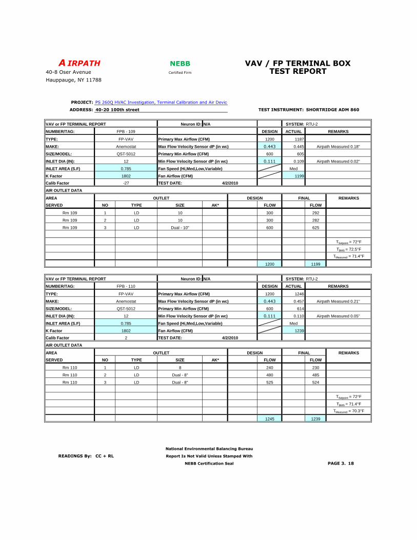
TYPE: Primary Max Airflow (CFM) 1200 1187
MAKE: Max Flow Velocity Sensor dP (in wc) 0.443 0.445
SIZE/MODEL: Primary Min Airflow (CFM) 600 605
INLET DIA (IN): Min Flow Velocity Sensor dP (in wc) 0.111 0.109
INLET AREA (S.F) Fan Speed (Hi,Med,Low,Variable) Med
K Factor Fan Airflow (CFM) 1199
Calib Factor TEST DATE:
AIR OUTLET DATA
AREA
SERVED NO AK* FLOW FLOW
Rm 109 1 300 292
Rm 109 2 300 282
Rm 109 3 600 625
1200 1199
VAV or FP TERMINAL REPORT SYSTEM: RTU-2
NUMBER/TAG: DESIGN ACTUAL
TYPE: Primary Max Airflow (CFM) 1200 1246
MAKE: Max Flow Velocity Sensor dP (in wc) 0.443 0.457
SIZE/MODEL: Primary Min Airflow (CFM) 600 614
INLET DIA (IN): Min Flow Velocity Sensor dP (in wc) 0.111 0.110
INLET AREA (S.F) Fan Speed (Hi,Med,Low,Variable) Med
K Factor Fan Airflow (CFM) 1239
Calib Factor TEST DATE:
AIR OUTLET DATA
AREA
SERVED NO AK* FLOW FLOW
Rm 110 1 240 230
Rm 110 2 480 485
Rm 110 3 525 524
1245 1239
READINGS By:
PAGE 3. 18
A IRPATH NEBBCertified Firm TEST REPORT
PS 260Q HVAC Investigation, Terminal Calibration and Air Device Balance
40-20 100th street
Neuron ID: N/A
FPB - 109 REMARKS
FP-VAV
Anemostat Airpath Measured 0.18"
QST-5012
12 Airpath Measured 0.02"
0.785
1802
-27 4/2/2010
OUTLET DESIGN FINAL REMARKS
TYPE SIZE
LD 10
LD 10
LD Dual - 10"
TSetpoint = 72°F
TBMS = 72.5°F
Neuron ID: N/A
FPB - 110 REMARKS
TMeasured = 71.4°F
FP-VAV
Anemostat Airpath Measured 0.21"
QST-5012
12 Airpath Measured 0.05"
0.785
1802
2 4/2/2010
OUTLET DESIGN FINAL REMARKS
TYPE SIZE
LD 8
LD Dual - 8"
LD Dual - 8"
TSetpoint = 72°F
TBMS = 71.4°F
TMeasured = 70.3°F
National Environmental Balancing Bureau
CC + RL Report Is Not Valid Unless Stamped With
NEBB Certification Seal

VAV / FP TERMINAL BOX40-8 Oser Avenue
Hauppauge, NY 11788
PROJECT:
ADDRESS: TEST INSTRUMENT: SHORTRIDGE ADM 860
VAV or FP TERMINAL REPORT SYSTEM: RTU-2
NUMBER/TAG: DESIGN ACTUAL
TYPE: Primary Max Airflow (CFM) 450 434
MAKE: Max Flow Velocity Sensor dP (in wc) 0.269 0.254
SIZE/MODEL: Primary Min Airflow (CFM) 225 213
INLET DIA (IN): Min Flow Velocity Sensor dP (in wc) 0.067 0.062
INLET AREA (S.F)
K Factor
Calib Factor TEST DATE:
AIR OUTLET DATA
AREA
SERVED NO AK* FLOW FLOW
Corridor 1 50 47
Corridor 2 100 96
Rm 113D 3 75 73
Medical Waiting Rm 113 4 75 74
111C 5 100 101
Duplication Area 109A 6 50 54
450 445
VAV or FP TERMINAL REPORT SYSTEM: RTU-2
NUMBER/TAG: DESIGN ACTUAL
TYPE: Primary Max Airflow (CFM) 900 911
MAKE: Max Flow Velocity Sensor dP (in wc) 0.442 0.446
SIZE/MODEL: Primary Min Airflow (CFM) 450 427
INLET DIA (IN): Min Flow Velocity Sensor dP (in wc) 0.111 0.098
INLET AREA (S.F) Fan Speed (Hi,Med,Low,Variable) Med
K Factor Fan Airflow (CFM) 904
Calib Factor TEST DATE:
AIR OUTLET DATA
AREA
SERVED NO AK* FLOW FLOW
Record Rm 109 1 150 155
Guidance Rm 111A 2 300 310
Conference Rm 111C 3 150 143
Exam Rm 113C 4 150 149
Nurse's Office 113A 5 150 147
900 904
READINGS By:
PAGE 3. 19
A IRPATH NEBBCertified Firm TEST REPORT
PS 260Q HVAC Investigation, Terminal Calibration and Air Device Balance
40-20 100th street
Neuron ID: N/A
VAV - 111C REMARKS
VAV
Anemostat Airpath Measured 0.18"
EZTS-08
8 Airpath Measured 0.06"
0.349
867
0 4/2/2010
OUTLET DESIGN FINAL REMARKS
TYPE SIZE
CD 8
CD 8
CD 8
CD 8
CD 8 TSetpoint = 70°F
CD 8 TBMS = 70.8°F
Neuron ID:
FPB - 111 REMARKS
TMeasured = 70.3°F
FP-VAV
Anemostat Airpath Measured 0.19
QST-2510
10 Airpath measured 0.02
0.545
1353
1 4/2/2010
OUTLET DESIGN FINAL REMARKS
TYPE SIZE
LD 8
LD Dual - 8"
LD 8"
LD 8"
LD 8" TSetpoint = 72°F
TBMS = 72.8°F
TMeasured = 71.9°F
National Environmental Balancing Bureau
CC + RL Report Is Not Valid Unless Stamped With
NEBB Certification Seal
VAV / FP TERMINAL BOX40-8 Oser Avenue
Hauppauge, NY 11788
PROJECT:
ADDRESS: TEST INSTRUMENT: SHORTRIDGE ADM 860
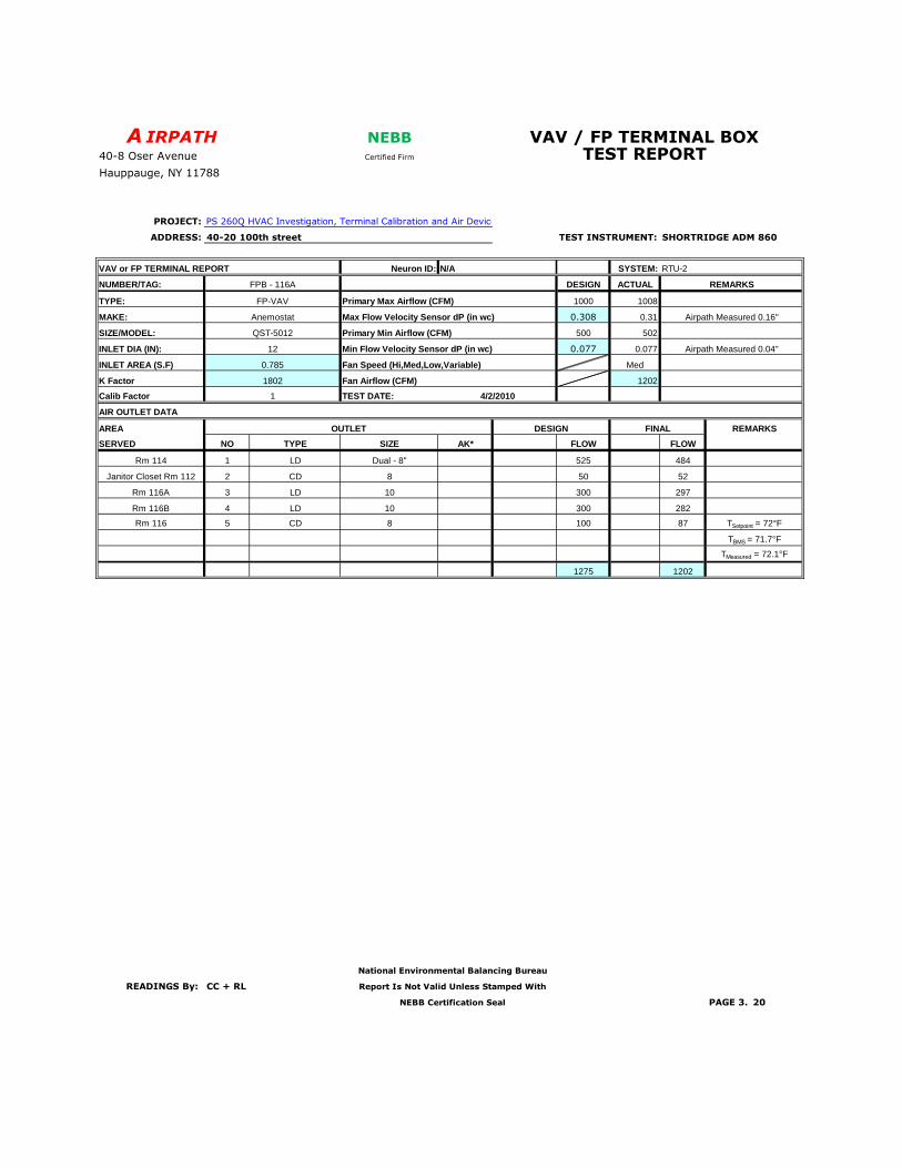
VAV or FP TERMINAL REPORT SYSTEM: RTU-2
NUMBER/TAG: DESIGN ACTUAL
TYPE: Primary Max Airflow (CFM) 1000 1008
MAKE: Max Flow Velocity Sensor dP (in wc) 0.308 0.31
SIZE/MODEL: Primary Min Airflow (CFM) 500 502
INLET DIA (IN): Min Flow Velocity Sensor dP (in wc) 0.077 0.077
INLET AREA (S.F) Fan Speed (Hi,Med,Low,Variable) Med
K Factor Fan Airflow (CFM) 1202
Calib Factor TEST DATE:
AIR OUTLET DATA
AREA
SERVED NO AK* FLOW FLOW
Rm 114 1 525 484
Janitor Closet Rm 112 2 50 52
Rm 116A 3 300 297
Rm 116B 4 300 282
Rm 116 5 100 87
1275 1202
READINGS By:
PAGE 3. 20
National Environmental Balancing Bureau
CC + RL Report Is Not Valid Unless Stamped With
NEBB Certification Seal
TBMS = 71.7°F
TMeasured = 72.1°F
LD 10
CD 8 TSetpoint = 72°F
CD 8
LD 10
TYPE SIZE
LD Dual - 8"
1 4/2/2010
OUTLET DESIGN FINAL REMARKS
12 Airpath Measured 0.04"
0.785
1802
REMARKS
FP-VAV
Anemostat Airpath Measured 0.16"
QST-5012
FPB - 116A
A IRPATH NEBBCertified Firm TEST REPORT
PS 260Q HVAC Investigation, Terminal Calibration and Air Device Balance
40-20 100th street
Neuron ID: N/A

VAV / FP TERMINAL BOX40-8 Oser Avenue
Hauppauge, NY 11788
PROJECT:
ADDRESS: TEST INSTRUMENT: SHORTRIDGE ADM 860
VAV or FP TERMINAL REPORT SYSTEM: RTU-2
NUMBER/TAG: DESIGN ACTUAL
TYPE: Primary Max Airflow (CFM) 1500 1518
MAKE: Max Flow Velocity Sensor dP (in wc) 0.369 0.379
SIZE/MODEL: Primary Min Airflow (CFM) 750 740
INLET DIA (IN): Min Flow Velocity Sensor dP (in wc) 0.092 0.083
INLET AREA (S.F) Fan Speed (Hi,Med,Low,Variable) Med
K Factor Fan Airflow (CFM) 1442
Calib Factor TEST DATE:
AIR OUTLET DATA
AREA
SERVED NO AK* FLOW FLOW
Rm 213 1 600 570
Rm 213 2 450 420
Rm 213 3 450 452
1500 1442
VAV or FP TERMINAL REPORT SYSTEM: RTU-2
NUMBER/TAG: DESIGN ACTUAL
TYPE: Primary Max Airflow (CFM) 1000 1002
MAKE: Max Flow Velocity Sensor dP (in wc) 0.308 0.311
SIZE/MODEL: Primary Min Airflow (CFM) 500 477
INLET DIA (IN): Min Flow Velocity Sensor dP (in wc) 0.077 0.063
INLET AREA (S.F) Fan Speed (Hi,Med,Low,Variable) Med
K Factor Fan Airflow (CFM) 905
Calib Factor TEST DATE:
AIR OUTLET DATA
AREA
SERVED NO AK* FLOW FLOW
Rm 214 1 500 455
Rm 214 2 500 450
1000 905
READINGS By:
PAGE 3. 21
A IRPATH NEBBCertified Firm TEST REPORT
PS 260Q HVAC Investigation, Terminal Calibration and Air Device Balance
40-20 100th street
Neuron ID: N/A
FPB - 213 REMARKS
FP-VAV
Anemostat Airpath Measured 0.17
QST-5014
14 Airpath Measured 0.04
1.068
2469
3 3/31/2010
OUTLET DESIGN FINAL REMARKS
TYPE SIZE
LD Dual - 10"
LD Dual - 8"
LD Dual - 8"
TSetpoint = 72°F
TBMS = 71.2°F
Neuron ID: N/A
FPB - 214 REMARKS
TMeasured = 70.1°F
FP-VAV
Anemostat Airpath Measured 0.18"
QST-5012
12 Airpath Measured 0.08"
0.785
1802
0 3/31/2010
OUTLET DESIGN FINAL REMARKS
TYPE SIZE
LD Dual - 8"
LD Dual - 8"
TSetpoint = 72°F
TBMS = 72.8°F
TMeasured = 73.5°F
National Environmental Balancing Bureau
Report Is Not Valid Unless Stamped With
NEBB Certification Seal

VAV / FP TERMINAL BOX40-8 Oser Avenue
Hauppauge, NY 11788
PROJECT:
ADDRESS: TEST INSTRUMENT: SHORTRIDGE ADM 860
VAV or FP TERMINAL REPORT SYSTEM: RTU-2
NUMBER/TAG: DESIGN ACTUAL
TYPE: Primary Max Airflow (CFM) 1000 1048
MAKE: Max Flow Velocity Sensor dP (in wc) 0.308 0.31
SIZE/MODEL: Primary Min Airflow (CFM) 500 478
INLET DIA (IN): Min Flow Velocity Sensor dP (in wc) 0.077 0.065
INLET AREA (S.F) Fan Speed (Hi,Med,Low,Variable) Med
K Factor Fan Airflow (CFM) 990
Calib Factor TEST DATE:
AIR OUTLET DATA
AREA
SERVED NO AK* FLOW FLOW
Rm 215 1 500 495
Rm 215 2 500 495
1000 990
VAV or FP TERMINAL REPORT SYSTEM: RTU-2
NUMBER/TAG: DESIGN ACTUAL
TYPE: Primary Max Airflow (CFM) 950 1095
MAKE: Max Flow Velocity Sensor dP (in wc) 0.278 0.357
SIZE/MODEL: Primary Min Airflow (CFM) 475 496
INLET DIA (IN): Min Flow Velocity Sensor dP (in wc) 0.069 0.068
INLET AREA (S.F) Fan Speed (Hi,Med,Low,Variable) Med
K Factor Fan Airflow (CFM) 966
Calib Factor TEST DATE:
AIR OUTLET DATA
AREA
SERVED NO AK* FLOW FLOW
Rm 216 1 525 482
Rm 216 2 525 484
1050 966
READINGS By:
PAGE 3. 22
A IRPATH NEBBCertified Firm TEST REPORT
PS 260Q HVAC Investigation, Terminal Calibration and Air Device Balance
40-20 100th street
Neuron ID: N/A
FPB - 215 REMARKS
FP-VAV
Anemostat Airpath Measured 0.13"
QST-5012
12 Airpath Measured 0.01"
0.785
1802
5 3/30/2010
OUTLET DESIGN FINAL REMARKS
TYPE SIZE
LD 8
LD 8
TSetpoint = 72°F
TBMS = 71.7°F
Neuron ID: N/A
FPB - 216 REMARKS
TMeasured = 70.3°F
FP-VAV
Anemostat Airpath Measured 0.13"
QST-5012
12 Airpath Measured 0.04"
0.785
1802
2 3/30/2010
OUTLET DESIGN FINAL REMARKS
TYPE SIZE
LD 8
LD 8
TSetpoint = 72°F
TBMS = 71.4°F
TMeasured = 72.7°F
National Environmental Balancing Bureau
CC + RL Report Is Not Valid Unless Stamped With
NEBB Certification Seal

VAV / FP TERMINAL BOX40-8 Oser Avenue
Hauppauge, NY 11788
PROJECT:
ADDRESS: TEST INSTRUMENT: SHORTRIDGE ADM 860
VAV or FP TERMINAL REPORT SYSTEM: RTU-2
NUMBER/TAG: DESIGN ACTUAL
TYPE: Primary Max Airflow (CFM) 950 937
MAKE: Max Flow Velocity Sensor dP (in wc) 0.278 0.261
SIZE/MODEL: Primary Min Airflow (CFM) 475 494
INLET DIA (IN): Min Flow Velocity Sensor dP (in wc) 0.069 0.071
INLET AREA (S.F) Fan Speed (Hi,Med,Low,Variable) Med
K Factor Fan Airflow (CFM) 977
Calib Factor TEST DATE:
AIR OUTLET DATA
AREA
SERVED NO AK* FLOW FLOW
Rm 307 1 500 489
Rm 307 2 450 488
950 977
VAV or FP TERMINAL REPORT SYSTEM: RTU-2
NUMBER/TAG: DESIGN ACTUAL
TYPE: Primary Max Airflow (CFM) 950 921
MAKE: Max Flow Velocity Sensor dP (in wc) 0.278 0.269
SIZE/MODEL: Primary Min Airflow (CFM) 475 479
INLET DIA (IN): Min Flow Velocity Sensor dP (in wc) 0.069 0.071
INLET AREA (S.F) Fan Speed (Hi,Med,Low,Variable) Med
K Factor Fan Airflow (CFM) 940
Calib Factor TEST DATE:
AIR OUTLET DATA
AREA
SERVED NO AK* FLOW FLOW
Rm 309 1 500 470
Rm 309 2 450 470
950 940
READINGS By:
PAGE 3. 23
A IRPATH NEBBCertified Firm TEST REPORT
PS 260Q HVAC Investigation, Terminal Calibration and Air Device Balance
40-20 100th street
Neuron ID: N/A
FPB - 307 REMARKS
FP-VAV
Anemostat Airpath Measured 0.14"
QST-5012
12 Airpath Measured 0.03"
0.785
1802
2 3/30/2010
OUTLET DESIGN FINAL REMARKS
TYPE SIZE
LD Dual - 8"
LD Dual - 8"
TSetpoint = 72°F
TBMS = 73.2°F
Neuron ID: N/A
FPB - 309 REMARKS
TMeasured = 72.7°F
FP-VAV
Anemostat Airpath Measured 0.17"
QST-5012
12 Airpath Measured 0.07"
0.785
1802
0 3/30/2010
OUTLET DESIGN FINAL REMARKS
TYPE SIZE
LD Dual - 8"
LD Dual - 8"
TSetpoint = 72°F
TBMS = 71.4°F
TMeasured = 71.3°F
National Environmental Balancing Bureau
CC + RL Report Is Not Valid Unless Stamped With
NEBB Certification Seal

VAV / FP TERMINAL BOX40-8 Oser Avenue
Hauppauge, NY 11788
PROJECT:
ADDRESS: TEST INSTRUMENT: SHORTRIDGE ADM 860
VAV or FP TERMINAL REPORT SYSTEM: RTU-2
NUMBER/TAG: DESIGN ACTUAL
TYPE: Primary Max Airflow (CFM) 1000 1004
MAKE: Max Flow Velocity Sensor dP (in wc) 0.308 0.296
SIZE/MODEL: Primary Min Airflow (CFM) 500 533
INLET DIA (IN): Min Flow Velocity Sensor dP (in wc) 0.077 0.083
INLET AREA (S.F) Fan Speed (Hi,Med,Low,Variable) Med
K Factor Fan Airflow (CFM) 986
Calib Factor TEST DATE:
AIR OUTLET DATA
AREA
SERVED NO AK* FLOW FLOW
Rm 311 1 500 493
Rm 311 2 500 493
1000 986
VAV or FP TERMINAL REPORT SYSTEM: RTU-2
NUMBER/TAG: DESIGN ACTUAL
TYPE: Primary Max Airflow (CFM) 1050 1030
MAKE: Max Flow Velocity Sensor dP (in wc) 0.340 0.321
SIZE/MODEL: Primary Min Airflow (CFM) 525 513
INLET DIA (IN): Min Flow Velocity Sensor dP (in wc) 0.085 0.084
INLET AREA (S.F) Fan Speed (Hi,Med,Low,Variable) Med
K Factor Fan Airflow (CFM) 980
Calib Factor TEST DATE:
AIR OUTLET DATA
AREA
SERVED NO AK* FLOW FLOW
Rm 314 1 525 490
Rm 314 2 525 490
1050 980
READINGS By:
PAGE 3. 24
A IRPATH NEBBCertified Firm TEST REPORT
PS 260Q HVAC Investigation, Terminal Calibration and Air Device Balance
40-20 100th street
Neuron ID: N/A
FPB - 311 REMARKS
FP-VAV
Anemostat Airpath Measured 0.16"
QST-5012
12 Airpath Measured 0.06"
0.785
1802
3 3/30/2010
OUTLET DESIGN FINAL REMARKS
TYPE SIZE
LD Dual - 8"
LD Dual - 8"
TSetpoint = 72°F
TBMS = 72.6°F
Neuron ID: N/A
FPB - 314 REMARKS
TMeasured = 71.1°F
FP-VAV
Anemostat Airpath Measured 0.25"
QST-5012
12 Airpath Measured 0.08"
0.785
1802
-2 3/30/2010
OUTLET DESIGN FINAL REMARKS
TYPE SIZE
LD Dual - 8"
LD Dual - 8"
TSetpoint = 72°F
TBMS = 71.6°F
TMeasured = 70.5°F
National Environmental Balancing Bureau
CC + RL Report Is Not Valid Unless Stamped With
NEBB Certification Seal
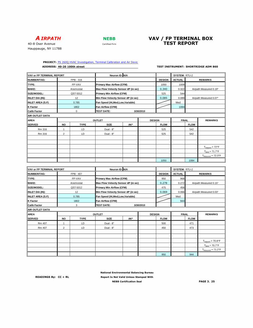
VAV / FP TERMINAL BOX40-8 Oser Avenue
Hauppauge, NY 11788
PROJECT:
ADDRESS: TEST INSTRUMENT: SHORTRIDGE ADM 860
VAV or FP TERMINAL REPORT SYSTEM: RTU-2
NUMBER/TAG: DESIGN ACTUAL
TYPE: Primary Max Airflow (CFM) 1050 1009
MAKE: Max Flow Velocity Sensor dP (in wc) 0.340 0.322
SIZE/MODEL: Primary Min Airflow (CFM) 525 544
INLET DIA (IN): Min Flow Velocity Sensor dP (in wc) 0.085 0.089
INLET AREA (S.F) Fan Speed (Hi,Med,Low,Variable) Med
K Factor Fan Airflow (CFM) 1084
Calib Factor TEST DATE:
AIR OUTLET DATA
AREA
SERVED NO AK* FLOW FLOW
Rm 316 1 525 542
Rm 316 2 525 542
1050 1084
VAV or FP TERMINAL REPORT SYSTEM: RTU-2
NUMBER/TAG: DESIGN ACTUAL
TYPE: Primary Max Airflow (CFM) 950 968
MAKE: Max Flow Velocity Sensor dP (in wc) 0.278 0.272
SIZE/MODEL: Primary Min Airflow (CFM) 475 456
INLET DIA (IN): Min Flow Velocity Sensor dP (in wc) 0.069 0.066
INLET AREA (S.F) Fan Speed (Hi,Med,Low,Variable) Med
K Factor Fan Airflow (CFM) 944
Calib Factor TEST DATE:
AIR OUTLET DATA
AREA
SERVED NO AK* FLOW FLOW
Rm 407 1 500 471
Rm 407 2 450 473
950 944
READINGS By:
PAGE 3. 25
A IRPATH NEBBCertified Firm TEST REPORT
PS 260Q HVAC Investigation, Terminal Calibration and Air Device Balance
40-20 100th street
Neuron ID: N/A
FPB - 316 REMARKS
FP-VAV
Anemostat Airpath Measured 0.19"
QST-5012
12 Airpath Measured 0.07"
0.785
1802
0 3/30/2010
OUTLET DESIGN FINAL REMARKS
TYPE SIZE
LD Dual - 8"
LD Dual - 8"
TSetpoint = 72°F
TBMS = 71.7°F
Neuron ID: N/A
FPB - 407 REMARKS
TMeasured = 72.3°F
FP-VAV
Anemostat Airpath Measured 0.15"
QST-5012
12 Airpath Measured 0.03"
0.785
1802
3 3/30/2010
OUTLET DESIGN FINAL REMARKS
TYPE SIZE
LD Dual - 8"
LD Dual - 8"
TSetpoint = 70.8°F
TBMS = 70.7°F
TMeasured = 71.2°F
National Environmental Balancing Bureau
CC + RL Report Is Not Valid Unless Stamped With
NEBB Certification Seal

VAV / FP TERMINAL BOX40-8 Oser Avenue
Hauppauge, NY 11788
PROJECT:
ADDRESS: TEST INSTRUMENT: SHORTRIDGE ADM 860
VAV or FP TERMINAL REPORT SYSTEM: RTU-2
NUMBER/TAG: DESIGN ACTUAL
TYPE: Primary Max Airflow (CFM) 950 957
MAKE: Max Flow Velocity Sensor dP (in wc) 0.278 0.271
SIZE/MODEL: Primary Min Airflow (CFM) 475 479
INLET DIA (IN): Min Flow Velocity Sensor dP (in wc) 0.069 0.065
INLET AREA (S.F) Fan Speed (Hi,Med,Low,Variable) Med
K Factor Fan Airflow (CFM) 960
Calib Factor TEST DATE:
AIR OUTLET DATA
AREA
SERVED NO AK* FLOW FLOW
Rm 409 1 500 480
Rm 409 2 450 480
950 960
VAV or FP TERMINAL REPORT SYSTEM: RTU-2
NUMBER/TAG: DESIGN ACTUAL
TYPE: Primary Max Airflow (CFM) 1000 1065
MAKE: Max Flow Velocity Sensor dP (in wc) 0.308 0.323
SIZE/MODEL: Primary Min Airflow (CFM) 500 489
INLET DIA (IN): Min Flow Velocity Sensor dP (in wc) 0.077 0.081
INLET AREA (S.F) Fan Speed (Hi,Med,Low,Variable) Med
K Factor Fan Airflow (CFM) 848
Calib Factor TEST DATE:
AIR OUTLET DATA
AREA
SERVED NO AK* FLOW FLOW
Rm 411 1 500 433
Rm 411 2 500 415
1000 848
READINGS By:
PAGE 3. 26
A IRPATH NEBBCertified Firm TEST REPORT
PS 260Q HVAC Investigation, Terminal Calibration and Air Device Balance
40-20 100th street
Neuron ID: N/A
FPB - 409 REMARKS
FP-VAV
Anemostat Airpath Measured 0.13"
QST-5012
12 Airpath Measured 0.03"
0.785
1802
3 3/30/2010
OUTLET DESIGN FINAL REMARKS
TYPE SIZE
LD Dual - 8"
LD Dual - 8"
TSetpoint = 72°F
TBMS = 72.5°F
Neuron ID: N/A
FPB - 411 REMARKS
TMeasured = 71.8°F
FP-VAV
Anemostat Airpath Measured 0.18"
QST-5012
12 Airpath Measured 0.05"
0.785
1802
2 3/29/2010
OUTLET DESIGN FINAL REMARKS
TYPE SIZE
LD Dual - 8"
LD Dual - 8"
TSetpoint = 72°F
TBMS = 71.4°F
TMeasured = 70.8°F
National Environmental Balancing Bureau
CC + RL Report Is Not Valid Unless Stamped With
NEBB Certification Seal

VAV / FP TERMINAL BOX40-8 Oser Avenue
Hauppauge, NY 11788
PROJECT:
ADDRESS: TEST INSTRUMENT: SHORTRIDGE ADM 860
VAV or FP TERMINAL REPORT SYSTEM: RTU-2
NUMBER/TAG: DESIGN ACTUAL
TYPE: Primary Max Airflow (CFM) 1050 1076
MAKE: Max Flow Velocity Sensor dP (in wc) 0.340 0.339
SIZE/MODEL: Primary Min Airflow (CFM) 525 561
INLET DIA (IN): Min Flow Velocity Sensor dP (in wc) 0.085 0.087
INLET AREA (S.F) Fan Speed (Hi,Med,Low,Variable) Med
K Factor Fan Airflow (CFM) 979
Calib Factor TEST DATE:
AIR OUTLET DATA
AREA
SERVED NO AK* FLOW FLOW
Rm 412 1 525 489
Rm 412 2 525 490
1050 979
VAV or FP TERMINAL REPORT SYSTEM: RTU-2
NUMBER/TAG: DESIGN ACTUAL
TYPE: Primary Max Airflow (CFM) 1050 1032
MAKE: Max Flow Velocity Sensor dP (in wc) 0.340 0.339
SIZE/MODEL: Primary Min Airflow (CFM) 525 696
INLET DIA (IN): Min Flow Velocity Sensor dP (in wc) 0.085 0.158
INLET AREA (S.F) Fan Speed (Hi,Med,Low,Variable) Med
K Factor Fan Airflow (CFM) 1096
Calib Factor TEST DATE:
AIR OUTLET DATA
AREA
SERVED NO AK* FLOW FLOW
Rm 414 1 525 548
Rm 414 2 525 548
1050 1096
READINGS By:
PAGE 3. 27
A IRPATH NEBBCertified Firm TEST REPORT
PS 260Q HVAC Investigation, Terminal Calibration and Air Device Balance
40-20 100th street
Neuron ID: N/A
FPB - 412 REMARKS
FP-VAV
Anemostat Airpath Measured 0.18"
QST-5012
12 Airpath Measured 0.05"
0.785
1802
2 3/30/2010
OUTLET DESIGN FINAL REMARKS
TYPE SIZE
LD Dual - 8"
LD Dual - 8"
TSetpoint = 72°F
TBMS = 71.6°F
Neuron ID: N/A
FPB - 414 REMARKS
TMeasured = 70.5°F
FP-VAV
Anemostat Airpath Measured 0.21"
QST-5012 Damper fully closed, terminal is
12 unable to achieve minimum flow.
0.785
1802
-3 3/29/2010
OUTLET DESIGN FINAL REMARKS
TYPE SIZE
LD Dual - 8"
LD Dual - 8"
TSetpoint = 72°F
TBMS = 71.4°F
TMeasured = 71.2°F
National Environmental Balancing Bureau
CC + RL Report Is Not Valid Unless Stamped With
NEBB Certification Seal

VAV / FP TERMINAL BOX40-8 Oser Avenue
Hauppauge, NY 11788
PROJECT:
ADDRESS: TEST INSTRUMENT: SHORTRIDGE ADM 860
VAV or FP TERMINAL REPORT SYSTEM: RTU-2
NUMBER/TAG: DESIGN ACTUAL
TYPE: Primary Max Airflow (CFM) 950 953
MAKE: Max Flow Velocity Sensor dP (in wc) 0.278 0.331
SIZE/MODEL: Primary Min Airflow (CFM) 475 402
INLET DIA (IN): Min Flow Velocity Sensor dP (in wc) 0.069 0.064
INLET AREA (S.F) Fan Speed (Hi,Med,Low,Variable) N/A
K Factor Fan Airflow (CFM) 0
Calib Factor TEST DATE:
AIR OUTLET DATA
AREA
SERVED NO AK* FLOW FLOW
Rm 507 1 500
Rm 507 2 450
950 0
VAV or FP TERMINAL REPORT SYSTEM: RTU-2
NUMBER/TAG: DESIGN ACTUAL
TYPE: Primary Max Airflow (CFM) 950 983
MAKE: Max Flow Velocity Sensor dP (in wc) 0.278 0.308
SIZE/MODEL: Primary Min Airflow (CFM) 475 460
INLET DIA (IN): Min Flow Velocity Sensor dP (in wc) 0.069 0.077
INLET AREA (S.F) Fan Speed (Hi,Med,Low,Variable) Low
K Factor Fan Airflow (CFM) 1000
Calib Factor TEST DATE:
AIR OUTLET DATA
AREA
SERVED NO AK* FLOW FLOW
Rm 509 1 500 525
Rm 509 2 450 475
950 1000
READINGS By:
PAGE 3. 28
A IRPATH NEBBCertified Firm TEST REPORT
PS 260Q HVAC Investigation, Terminal Calibration and Air Device Balance
40-20 100th street
Neuron ID: N/A
FPB - 507 REMARKS
FP-VAV
Anemostat Airpath Measured 0.24"
QST-5012
12 Airpath Measured 0.07"
0.785
1802 Fan failure, no fan flow
-10 5/29/2010
OUTLET DESIGN FINAL REMARKS
TYPE SIZE
LD Dual - 8" Fan Failure, no fan flow
LD Dual - 8"
TSetpoint = 72°F
TBMS = 68.5°F
Neuron ID: N/A
FPB - 509 REMARKS
TMeasured = 68.6°F
FP-VAV
Anemostat Airpath Measured 0.25"
QST-5012
12 Airpath Measured 0.10"
0.785
1802
0 3/29/2010
OUTLET DESIGN FINAL REMARKS
TYPE SIZE
LD Dual - 8"
LD Dual - 8"
TSetpoint = 72°F
TBMS = 72.3°F
TMeasured = 75.1°F
National Environmental Balancing Bureau
CC + RL Report Is Not Valid Unless Stamped With
NEBB Certification Seal

VAV / FP TERMINAL BOX40-8 Oser Avenue
Hauppauge, NY 11788
PROJECT:
ADDRESS: TEST INSTRUMENT: SHORTRIDGE ADM 860
VAV or FP TERMINAL REPORT SYSTEM: RTU-2
NUMBER/TAG: DESIGN ACTUAL
TYPE: Primary Max Airflow (CFM) 1000 958
MAKE: Max Flow Velocity Sensor dP (in wc) 0.308 0.31
SIZE/MODEL: Primary Min Airflow (CFM) 500 517
INLET DIA (IN): Min Flow Velocity Sensor dP (in wc) 0.077 0.081
INLET AREA (S.F) Fan Speed (Hi,Med,Low,Variable) Med
K Factor Fan Airflow (CFM) 950
Calib Factor TEST DATE:
AIR OUTLET DATA
AREA
SERVED NO AK* FLOW FLOW
Rm 511 1 500 475
Rm 511 2 500 475
1000 950
VAV or FP TERMINAL REPORT SYSTEM: RTU-2
NUMBER/TAG: DESIGN ACTUAL
TYPE: Primary Max Airflow (CFM) 1050 1028
MAKE: Max Flow Velocity Sensor dP (in wc) 0.340 0.325
SIZE/MODEL: Primary Min Airflow (CFM) 525 458
INLET DIA (IN): Min Flow Velocity Sensor dP (in wc) 0.085 0.06
INLET AREA (S.F) Fan Speed (Hi,Med,Low,Variable) Low
K Factor Fan Airflow (CFM) 1055
Calib Factor TEST DATE:
AIR OUTLET DATA
AREA
SERVED NO AK* FLOW FLOW
Rm 512 1 525 530
Rm 512 2 525 525
1050 1055
READINGS By:
PAGE 3. 29
A IRPATH NEBBCertified Firm TEST REPORT
PS 260Q HVAC Investigation, Terminal Calibration and Air Device Balance
40-20 100th street
Neuron ID: N/A
FPB - 511 REMARKS
FP-VAV
Anemostat Airpath Measured 0.26"
QST-5012
12 Airpath Measured 0.07"
0.785
1802
-10 3/29/2010
OUTLET DESIGN FINAL REMARKS
TYPE SIZE
LD Dual - 8"
LD Dual - 8"
TSetpoint = 76°F
TBMS = 76.5°F
Neuron ID: N/A
FPB - 512 REMARKS
TMeasured = 75.5°F
FP-VAV
Anemostat Airpath Measured 0.22"
QST-5012
12 Airpath Measured 0.03"
0.785
1802
0 3/29/2010
OUTLET DESIGN FINAL REMARKS
TYPE SIZE
LD Dual - 8"
LD Dual - 8"
TSetpoint = 72°F
TBMS = 72.3°F
TMeasured = 73.2°F
National Environmental Balancing Bureau
CC + RL Report Is Not Valid Unless Stamped With
NEBB Certification Seal

VAV / FP TERMINAL BOX40-8 Oser Avenue
Hauppauge, NY 11788
PROJECT:
ADDRESS: TEST INSTRUMENT: SHORTRIDGE ADM 860
VAV or FP TERMINAL REPORT SYSTEM: RTU-2
NUMBER/TAG: DESIGN ACTUAL
TYPE: Primary Max Airflow (CFM) 1050 1038
MAKE: Max Flow Velocity Sensor dP (in wc) 0.340 0.341
SIZE/MODEL: Primary Min Airflow (CFM) 525 485
INLET DIA (IN): Min Flow Velocity Sensor dP (in wc) 0.085 0.076
INLET AREA (S.F) Fan Speed (Hi,Med,Low,Variable) Low
K Factor Fan Airflow (CFM) 1140
Calib Factor TEST DATE:
AIR OUTLET DATA
AREA
SERVED NO AK* FLOW FLOW
Rm 514 1 525 570
Rm 514 2 525 570
1050 1140
24200 24408
12100 12118
24620 23231
READINGS By:
PAGE 3. 30
A IRPATH NEBBCertified Firm TEST REPORT
PS 260Q HVAC Investigation, Terminal Calibration and Air Device Balance
40-20 100th street
Neuron ID: N/A
FPB - 514 REMARKS
FP-VAV
Anemostat Airpath Measured 0.25"
QST-5012
12 Airpath Measured 0.09"
0.785
1802
-3 3/29/2010
OUTLET DESIGN FINAL REMARKS
TYPE SIZE
LD Dual - 8"
LD Dual - 8"
CC + RL Report Is Not Valid Unless Stamped With
Total VAV Max Design CFM for RTU-2 = Total VAV Max Actual CFM for RTU-2 =
Total VAV Min Design CFM for RTU-2 = Total VAV Min Actual CFM for RTU-2 =
Total Outlets Design CFM for RTU-2 = Total Outlets Actual CFM for RTU-2 =
National Environmental Balancing Bureau
TSetpoint = 72°F
TMeasured = 76.0°F
TBMS = 71.3°F
NEBB Certification Seal
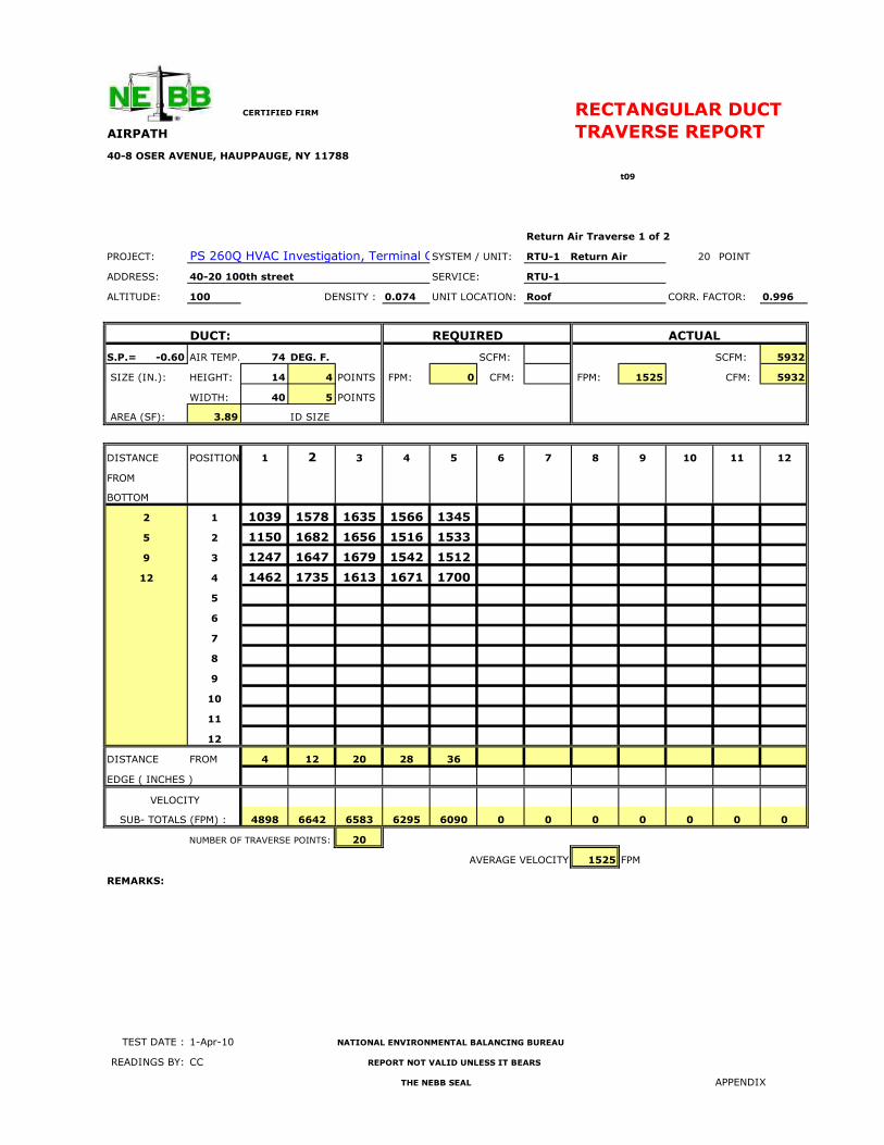
CERTIFIED FIRM RECTANGULAR DUCT
AIRPATH TRAVERSE REPORT
40-8 OSER AVENUE, HAUPPAUGE, NY 11788
t09
Return Air Traverse 1 of 2
PROJECT: SYSTEM / UNIT: 20 POINT
ADDRESS: SERVICE:
ALTITUDE: 100 DENSITY : 0.074 UNIT LOCATION: CORR. FACTOR: 0.996
DUCT: REQUIRED ACTUAL
S.P.= -0.60 AIR TEMP. 74 DEG. F. SCFM: SCFM: 5932
SIZE (IN.): HEIGHT: 14 4 POINTS FPM: 0 CFM: FPM: 1525 CFM: 5932
WIDTH: 40 5 POINTS
AREA (SF): 3.89 ID SIZE
DISTANCE POSITION 1 2 3 4 5 6 7 8 9 10 11 12
FROM
BOTTOM
1 1039 1578 1635 1566 1345
2 1150 1682 1656 1516 1533
3 1247 1647 1679 1542 1512
4 1462 1735 1613 1671 1700
5
6
7
8
9
10
11
12
DISTANCE FROM 4 12 20 28 36
EDGE ( INCHES )
4898 6642 6583 6295 6090 0 0 0 0 0 0 0
NUMBER OF TRAVERSE POINTS: 20
AVERAGE VELOCITY 1525 FPM
REMARKS:
NATIONAL ENVIRONMENTAL BALANCING BUREAU
CC REPORT NOT VALID UNLESS IT BEARS
THE NEBB SEAL APPENDIX
Roof
RTU-1 Return Air
RTU-1
PS 260Q HVAC Investigation, Terminal Calibration and Air Device Balance
40-20 100th street
VELOCITY
SUB- TOTALS (FPM) :
9
12
READINGS BY:
TEST DATE : 1-Apr-10
2
5

CERTIFIED FIRM RECTANGULAR DUCT
AIRPATH TRAVERSE REPORT
40-8 OSER AVENUE, HAUPPAUGE, NY 11788
t09
Return Air Traverse 2 of 2
PROJECT: SYSTEM / UNIT: 36 POINT
ADDRESS: SERVICE:
ALTITUDE: 100 DENSITY : 0.074 UNIT LOCATION: CORR. FACTOR: 0.996
DUCT: REQUIRED ACTUAL
S.P.= -0.45 AIR TEMP. 74 DEG. F. SCFM: SCFM: 12835
SIZE (IN.): HEIGHT: 22 4 POINTS FPM: 0 CFM: FPM: 1077 CFM: 12835
WIDTH: 78 9 POINTS
AREA (SF): 11.92 ID SIZE
DISTANCE POSITION 1 2 3 4 5 6 7 8 9 10 11 12
FROM
BOTTOM
1 1156 1169 1252 1167 810 1283 946 851 783
2 1165 1272 1238 1086 947 1454 1056 810 860
3 1162 1223 1272 1171 938 1317 1116 881 854
4 1239 1244 1108 977 945 1054 1117 896 955
5
6
7
8
9
10
11
12
DISTANCE FROM 4 13 22 30 39 48 56 65 74
EDGE ( INCHES )
4722 4908 4870 4401 3640 5108 4235 3438 3452 0 0 0
NUMBER OF TRAVERSE POINTS: 36
AVERAGE VELOCITY 1077 FPM
REMARKS:
NATIONAL ENVIRONMENTAL BALANCING BUREAU
CC REPORT NOT VALID UNLESS IT BEARS
THE NEBB SEAL APPENDIX
PS 260Q HVAC Investigation, Terminal Calibration and Air Device BalanceRTU-1 Return Air
40-20 100th street RTU-1
Roof
3
8
14
19
VELOCITY
SUB- TOTALS (FPM) :
TEST DATE : 1-Apr-10
READINGS BY:

CERTIFIED FIRM RECTANGULAR DUCT
AIRPATH TRAVERSE REPORT
40-8 OSER AVENUE, HAUPPAUGE, NY 11788
t09
Return Air Traverse 1 of 3
PROJECT: SYSTEM / UNIT: 16 POINT
ADDRESS: SERVICE:
ALTITUDE: 100 DENSITY : 0.074 UNIT LOCATION: CORR. FACTOR: 0.996
DUCT: REQUIRED ACTUAL
S.P.= -0.62 AIR TEMP. 74 DEG. F. SCFM: SCFM: 6481
SIZE (IN.): HEIGHT: 12 4 POINTS FPM: 0 CFM: FPM: 2160 CFM: 6481
WIDTH: 36 4 POINTS
AREA (SF): 3.00 ID SIZE
DISTANCE POSITION 1 2 3 4 5 6 7 8 9 10 11 12
FROM
BOTTOM
1 2183 2104 2135 2241
2 2362 2101 2115 2236
3 1969 2167 2053 2116
4 2151 2177 2210 2245
5
6
7
8
9
10
11
12
DISTANCE FROM 5 14 23 32
EDGE ( INCHES )
8665 8549 8513 8838 0 0 0 0 0 0 0 0
NUMBER OF TRAVERSE POINTS: 16
AVERAGE VELOCITY 2160 FPM
REMARKS:
NATIONAL ENVIRONMENTAL BALANCING BUREAU
CC REPORT NOT VALID UNLESS IT BEARS
THE NEBB SEAL APPENDIX
PS 260Q HVAC Investigation, Terminal Calibration and Air Device BalanceRTU-2 Return Air
40-20 100th street RTU-2
Roof
2
5
8
11
VELOCITY
SUB- TOTALS (FPM) :
TEST DATE : 1-Apr-10
READINGS BY:
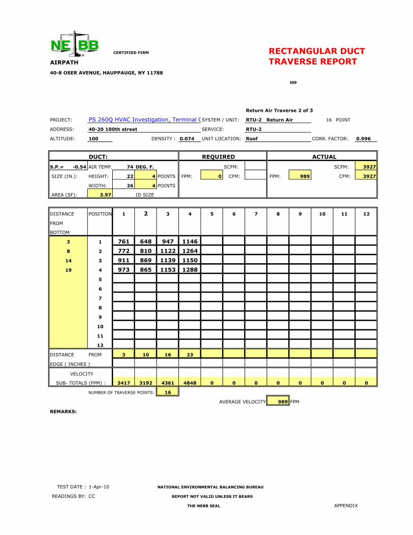
CERTIFIED FIRM RECTANGULAR DUCT
AIRPATH TRAVERSE REPORT
40-8 OSER AVENUE, HAUPPAUGE, NY 11788
t09
Return Air Traverse 2 of 3
PROJECT: SYSTEM / UNIT: 16 POINT
ADDRESS: SERVICE:
ALTITUDE: 100 DENSITY : 0.074 UNIT LOCATION: CORR. FACTOR: 0.996
DUCT: REQUIRED ACTUAL
S.P.= -0.54 AIR TEMP. 74 DEG. F. SCFM: SCFM: 3927
SIZE (IN.): HEIGHT: 22 4 POINTS FPM: 0 CFM: FPM: 989 CFM: 3927
WIDTH: 26 4 POINTS
AREA (SF): 3.97 ID SIZE
DISTANCE POSITION 1 2 3 4 5 6 7 8 9 10 11 12
FROM
BOTTOM
1 761 648 947 1146
2 772 810 1122 1264
3 911 869 1139 1150
4 973 865 1153 1288
5
6
7
8
9
10
11
12
DISTANCE FROM 3 10 16 23
EDGE ( INCHES )
3417 3192 4361 4848 0 0 0 0 0 0 0 0
NUMBER OF TRAVERSE POINTS: 16
AVERAGE VELOCITY 989 FPM
REMARKS:
NATIONAL ENVIRONMENTAL BALANCING BUREAU
CC REPORT NOT VALID UNLESS IT BEARS
THE NEBB SEAL APPENDIX
PS 260Q HVAC Investigation, Terminal Calibration and Air Device BalanceRTU-2 Return Air
40-20 100th street RTU-2
Roof
3
8
14
19
VELOCITY
SUB- TOTALS (FPM) :
TEST DATE : 1-Apr-10
READINGS BY:

CERTIFIED FIRM RECTANGULAR DUCT
AIRPATH TRAVERSE REPORT
40-8 OSER AVENUE, HAUPPAUGE, NY 11788
t09
Return Air Traverse 3 of 3
PROJECT: SYSTEM / UNIT: 24 POINT
ADDRESS: SERVICE:
ALTITUDE: 100 DENSITY : 0.074 UNIT LOCATION: CORR. FACTOR: 0.996
DUCT: REQUIRED ACTUAL
S.P.= -0.46 AIR TEMP. 74 DEG. F. SCFM: SCFM: 5548
SIZE (IN.): HEIGHT: 22 4 POINTS FPM: 0 CFM: FPM: 648 CFM: 5548
WIDTH: 56 6 POINTS
AREA (SF): 8.56 ID SIZE
DISTANCE POSITION 1 2 3 4 5 6 7 8 9 10 11 12
FROM
BOTTOM
1 1097 648 617 793 874 416
2 1107 733 617 1002 425 137
3 938 653 708 914 251 264
4 977 757 372 757 258 247
5
6
7
8
9
10
11
12
DISTANCE FROM 5 14 23 33 42 51
EDGE ( INCHES )
4119 2791 2314 3466 1808 1064 0 0 0 0 0 0
NUMBER OF TRAVERSE POINTS: 24
AVERAGE VELOCITY 648 FPM
REMARKS:
NATIONAL ENVIRONMENTAL BALANCING BUREAU
CC REPORT NOT VALID UNLESS IT BEARS
THE NEBB SEAL APPENDIX
PS 260Q HVAC Investigation, Terminal Calibration and Air Device BalanceRTU-2 Return Air
40-20 100th street RTU-2
Roof
3
8
14
19
READINGS BY:
VELOCITY
SUB- TOTALS (FPM) :
TEST DATE : 1-Apr-10

NEBB CERTIFIED FIRM ABBREVIATIONS
AIRPATH ABBR
40-8 OSER AVENUE, HAUPPAUGE, NY 11788
1WCD ONE WAY BLOW PATTERN CEILING DIFFUSER PF POWER FACTOR
2WCD TWO WAY BLOW PATTERN CEILING DIFFUSER PSI POUNDS PER SQUARE INCH PRESSURE
3WCD THREE WAY BLOW PATTERN CEILING DIFFUSER PSID POUNDS PER SQUARE INCH DIFFERENTIAL PRESSURE
4WCD FOUR WAY BLOW PATTERN CEILING DIFFUSER PSIG POUNDS PER SQUARE INCH GAUGE PRESSURE
bHP BRAKE HORSE POWER PT PITOT TRAVERSE
BR BOTTOM REGISTER QD QUADRANT DAMPER
CD CEILING DIFFUSER RA RETURN AIR
CF CUBIC FEET VOLUME RG RETURN AIR GRILLE
CL CENTER LINE RND ROUND
CR CEILING REGISTER RPM REVOLUTIONS PER MINUTE ROTATIONAL SPEED
CFM CUBIC FEET PER MINUTE AIR FLOW RVA ROTATING VANE ANEMOMETER
DIA. DIAMETER RR RETURN AIR REGISTER
D.N.A. DATA NOT AVAILABLE SA SUPPLY AIR
D.N.L. DATA NOT LEGIBLE OR AVAILABLE ON EQUIPMENT SR SUPPLY AIR REGISTER
EA EXHAUST AIR SLD SLOT LINEAR DIFFUSER
EG EXHAUST GRILLE SQFT SQUARE FEET AREA
EFF EFFICIENCY S.P. STATIC PRESSURE
FPM FEET PER MINUTE AIR VELOCITY T.P. TOTAL PRESSURE
FPS FEET PER SECOND WATER VELOCITY TR TOP REGISTER
FT FOOT ( FEET) LENGTH V.P. VELOCITY PRESSURE
HP HORSE POWER VD VOLUME DAMPER
IN. WC INCHES WATER COLUMN PRESSURE
GPM GALLONS PER MINUTE FLOW
LD LINEAR DIFFUSER
N.A. NOT ACCESSIBLE
N.I. NOT INSTALLED
N.S. NOT SPECIFIED
OA OUTSIDE AIR
APPENDIX